21 3214305 en om - ktm
TRANSCRIPT

OWNER'S MANUAL 2021
1290 SUPER DUKE RArt. no. 3214305en


DEAR KTM CUSTOMER
*3214305en*3214305en
11/2020
DEAR KTM CUSTOMER
Congratulations on your decision to purchase a KTM motorcycle. You are now the owner of a state-of-the-artsports motorcycle that will give you enormous pleasure if you service and maintain it properly.
We hope you enjoy riding this vehicle!
Enter the serial numbers of your vehicle below.
Vehicle identification number ( p. 34) Dealer's stamp
Engine number ( p. 36)
Key number ( p. 35)
The Owner's Manual contained the latest information for this model series at the time of publication. However,minor differences due to further developments in design cannot be ruled out completely.
All specifications contained herein are non-binding. KTM Sportmotorcycle GmbH specifically reserves the rightto modify or delete technical specifications, prices, colors, forms, materials, services, designs, equipment, etc.,without prior notice and without specifying reasons, to adapt these to local conditions, as well as to stop produc-tion of a particular model without prior notice. KTM accepts no liability for delivery options, deviations from fig-ures and descriptions, misprints, and other errors. The models portrayed partly contain special equipment thatdoes not belong to the regular scope of supply.

DEAR KTM CUSTOMER
2
© 2020 KTM Sportmotorcycle GmbH, Mattighofen Austria
All rights reservedReproduction, even in part, as well as copying of all kinds, is permitted only with the express written permissionof the copyright owner.
ISO 9001(12 100 6061)KTM applies quality assurance processes that lead to the highest possible product quality asdefined in the ISO 9001 international quality management standard.Issued by: TÜV Management Service
KTM Sportmotorcycle GmbHStallhofnerstraße 35230 Mattighofen, Austria
This document is valid for the following models:
1290 SUPER DUKE R US (F9975U2, F9975U9)

TABLE OF CONTENTS
3
TABLE OF CONTENTS
1 MEANS OF REPRESENTATION .................... 11
1.1 Symbols used .................................. 111.2 Formats used................................... 12
2 SAFETY ADVICE.......................................... 13
2.1 Use definition – intended use............ 132.2 Misuse............................................ 132.3 Safety advice................................... 132.4 Degrees of risk and symbols .............. 142.5 Overview of labels ............................ 162.6 Reporting safety defects ................... 212.7 Noise emission warranty ................... 212.8 Operating noise warning ................... 222.9 Manufacturer warranty for the
exhaust monitoring system................ 222.10 Consumer rights............................... 232.11 Tampering warning........................... 232.12 Safe operation ................................. 242.13 Protective clothing ........................... 252.14 Work rules....................................... 262.15 Environment.................................... 262.16 Owner's Manual ............................... 27
3 IMPORTANT NOTES.................................... 28
3.1 Manufacturer warranty, impliedwarranty.......................................... 28
3.2 Fuel, auxiliary substances ................. 283.3 Spare parts, accessories ................... 283.4 Service ........................................... 293.5 Figures ........................................... 293.6 Customer service.............................. 29
4 VIEW OF VEHICLE ...................................... 30
4.1 View of vehicle, front left (example) ... 304.2 View of vehicle, rear right
(example)........................................ 32
5 SERIAL NUMBERS ..................................... 34
5.1 Vehicle identification number............ 345.2 Type label ....................................... 345.3 Key number..................................... 355.4 Engine number ................................ 365.5 Fork part number ............................. 365.6 Shock absorber article number .......... 375.7 Steering damper article number ........ 37
6 CONTROLS................................................. 38
6.1 Clutch lever..................................... 38

TABLE OF CONTENTS
4
6.2 Hand brake lever.............................. 386.3 Throttle grip .................................... 396.4 Combination switch, left side ............ 396.5 Light switch .................................... 406.6 Menu buttons .................................. 416.7 Turn signal switch............................ 426.8 Horn button..................................... 436.9 Cruise control buttons ...................... 436.10 +RES/-SET button............................ 466.11 Combination switch, right ................. 476.12 Hazard warning flasher switch ........... 486.13 Start button/emergency OFF switch ... 496.14 RACE-ON button.............................. 506.15 C1 and C2 switch ............................ 516.16 Steering lock (antenna)..................... 516.17 Immobilizer ..................................... 526.18 RACE-ON key .................................. 536.19 Opening fuel tank filler cap............... 546.20 Closing the fuel tank filler cap........... 566.21 Seat lock......................................... 576.22 Tool set........................................... 576.23 Supporting strap .............................. 586.24 Passenger foot pegs ......................... 586.25 Shift lever ....................................... 596.26 Foot brake lever ............................... 606.27 Side stand....................................... 60
7 COMBINATION INSTRUMENT ..................... 62
7.1 Combination instrument ................... 627.2 Activation and test ........................... 637.3 Day-night mode ............................... 657.4 Warnings......................................... 667.5 Ice warning ..................................... 677.6 Indicator lamps................................ 687.7 Display ........................................... 727.8 TRACK Display (optional).................. 747.9 Performance layout (optional)............ 767.10 Small widget ................................... 787.11 Large widget.................................... 807.12 Odometer ........................................ 817.13 Engine speed................................... 827.14 Shift warning light ........................... 827.15 Cruise control indicator..................... 837.16 Speed............................................. 847.17 ABS Mode display............................ 847.18 Ride display .................................... 857.19 Gear display .................................... 857.20 Heated grip (optional)....................... 867.21 Seat heater (optional) ....................... 867.22 Coolant temperature indicator ........... 877.23 Fuel level display ............................. 877.24 Ambient air temperature indicator ..... 88

TABLE OF CONTENTS
5
7.25 Time............................................... 897.26 Favourites display ............................ 897.27 Navigation display (optional) ............. 907.28 Menu.............................................. 917.28.1 KTM MY RIDE (optional) .............. 917.28.2 Audio (optional) ........................... 927.28.3 Navigation (optional) .................... 947.28.4 Navigation information
(optional) .................................... 957.28.5 Volume (optional) ........................ 967.28.6 Pairing (optional) ......................... 987.28.7 Telephony (optional) .................. 1017.28.8 Trip 1 ....................................... 1027.28.9 Trip 2 ....................................... 1037.28.10 General Info ............................. 1047.28.11 TPMS ....................................... 1057.28.12 Warnings................................... 1067.28.13 Service ..................................... 1077.28.14 Extra Functions ......................... 1077.28.15 Ride Mode ................................ 1087.28.16 Track (optional) ......................... 1097.28.17 Throttle Response (optional) ....... 1107.28.18 Anti Wheelie Mode (optional) ...... 1117.28.19 Launch Control (optional) ........... 1127.28.20 Motorcycle ................................ 1137.28.21 Heated Grips (optional) .............. 113
7.28.22 Heated Seat (optional) ............... 1147.28.23 MTC+MSR (optional).................. 1157.28.24 ABS.......................................... 1167.28.25 Quickshifter + (optional)............. 1177.28.26 Settings .................................... 1177.28.27 C1 and C2 buttons..................... 1187.28.28 Bluetooth (optional) ................... 1197.28.29 Headset Type ............................ 1207.28.30 Display Theme........................... 1217.28.31 Button Illumination.................... 1227.28.32 Shift Light ................................ 1237.28.33 Daytime Runn. Light .................. 1247.29 Setting the time and date ............... 1257.30 Units ............................................ 1277.31 Distance ....................................... 1287.32 Temperature.................................. 1297.33 Pressure........................................ 1307.34 Consumption ................................. 1317.35 Language ...................................... 1327.36 Heated Grips (optional)................... 1337.37 Heated Seat (optional).................... 1347.38 Small widget ................................. 1357.39 Large widget.................................. 1357.40 KTM MY RIDE widget..................... 1367.41 NAVIGATION widget....................... 1377.42 FAVORITES widget......................... 138

TABLE OF CONTENTS
6
7.43 Widget INFO.................................. 1397.44 HEATING widget............................ 1407.45 MUSIC widget ............................... 141
8 ERGONOMICS .......................................... 143
8.1 Handlebar position......................... 1438.2 Adjusting the handlebar
position ..................................... 1438.3 Adjusting the basic position of the
clutch lever ................................... 1458.4 Adjusting the basic position of the
hand brake lever ............................ 1468.5 Setting the step plate of the foot
brake lever .................................... 1478.6 Checking the basic position of the
shift lever...................................... 1488.7 Setting the shift lever stub.............. 1498.8 Adjusting the footrests ................ 1508.9 Adjusting the tilt of the
combination instrument.................. 154
9 PREPARING FOR USE............................... 157
9.1 Advice on preparing for first use ...... 1579.2 Running in the engine .................... 1599.3 Loading the vehicle ........................ 159
10 RIDING INSTRUCTIONS............................ 162
10.1 Checks and maintenance measureswhen preparing for use ................... 162
10.2 Starting the vehicle ........................ 16310.3 Launch Control (optional) ............... 16610.4 Starting off.................................... 16610.5 Starting off with launch control
(optional) ...................................... 16710.6 Quickshifter+ (optional) .................. 16810.7 Shifting, riding .............................. 16910.8 MSR (optional) .............................. 17510.9 Applying the brakes........................ 17610.10 Stopping, parking........................... 17810.11 Transporting .................................. 18010.12 Refueling ...................................... 182
11 SERVICE SCHEDULE ................................ 185
11.1 Additional information.................... 18511.2 Required work ............................... 18511.3 Recommended work ....................... 188
12 SUSPENSION SETTING............................. 190
12.1 Fork/shock absorber ....................... 19012.2 Adjusting the spring preload of the
fork .............................................. 190

TABLE OF CONTENTS
7
12.3 Adjusting the compressiondamping of the fork........................ 191
12.4 Adjusting the rebound damping ofthe fork......................................... 193
12.5 Bleeding the fork legs..................... 19412.6 Compression damping of the shock
absorber........................................ 19512.7 Adjusting the spring preload of the
shock absorber .............................. 19612.8 Adjusting the low-speed
compression damping of the shockabsorber........................................ 196
12.9 Adjusting the high-speedcompression damping of the shockabsorber........................................ 198
12.10 Adjusting the rebound damping ofthe shock absorber ......................... 199
13 SERVICE WORK ON THE CHASSIS............. 201
13.1 Lifting the motorcycle with the rearlifting gear .................................... 201
13.2 Removing the rear of motorcyclefrom the lifting gear ....................... 201
13.3 Lifting the motorcycle with thefront lifting gear............................. 202
13.4 Taking the motorcycle off the frontlifting gear .................................... 203
13.5 Raising the motorcycle with thework stand (inserted) .................. 204
13.6 Removing the motorcycle from thework stand (inserted) .................. 206
13.7 Cleaning the dust boots of the forklegs ........................................... 207
13.8 Removing the passenger seat .......... 20913.9 Mounting the passenger seat........... 21013.10 Removing the front rider's seat ........ 21113.11 Mounting the front rider's seat......... 21213.12 Removing left fuel tank spoiler ........ 21313.13 Installing the left fuel tank spoiler ... 21513.14 Removing the main silencer ........ 21813.15 Installing the main silencer ......... 22013.16 Checking the chain for dirt.............. 22213.17 Cleaning the chain ......................... 22213.18 Checking the chain tension ............. 22413.19 Adjusting the chain tension............. 22613.20 Checking the chain, rear sprocket,
engine sprocket, and chain guide .... 22713.21 Checking/correcting the fluid level
of the hydraulic clutch.................... 232

TABLE OF CONTENTS
8
14 BRAKE SYSTEM ....................................... 235
14.1 Anti-lock braking system (ABS) ....... 23514.2 Checking the brake discs ................ 23814.3 Checking the front brake fluid
level ............................................. 23914.4 Adding front brake fluid .............. 24014.5 Checking the front brake linings ...... 24314.6 Checking the rear brake fluid
level ............................................. 24414.7 Adding rear brake fluid ............... 24514.8 Checking the brake linings of the
rear brake...................................... 248
15 WHEELS, TIRES ....................................... 249
15.1 Removing the front wheel ............ 24915.2 Installing the front wheel ............ 25115.3 Removing the rear wheel ............. 25415.4 Installing the rear wheel .............. 25515.5 Checking the tire condition ............. 25715.6 Checking tire pressure .................... 26015.7 Using tire repair spray .................... 261
16 ELECTRICAL SYSTEM ............................... 262
16.1 Low beam ..................................... 26216.2 High beam .................................... 262
16.3 Daytime running light (DRL)............. 26316.4 Removing the 12-V battery .......... 26416.5 Installing the 12-V battery ........... 26616.6 Charging the 12-V battery ........... 26916.7 Changing the RACE-ON key
battery .......................................... 27316.8 Changing the main fuse.................. 27516.9 Changing the fuses in the fuse
box ............................................... 27716.10 Changing the turn signal bulb ......... 28016.11 Checking the headlight setting ........ 28216.12 Adjusting the headlight range.......... 28316.13 Connecting the USB cable .............. 28416.14 Disconnecting the USB cable.......... 28516.15 Diagnostics connector .................... 28516.16 Front ACC1 and ACC2 .................... 28616.17 ACC1 and ACC2 rear ...................... 286
17 COOLING SYSTEM.................................... 287
17.1 Checking the coolant level in thecompensating tank......................... 287
17.2 Correcting the coolant level in thecompensating tank......................... 289
18 ENGINE TUNING ...................................... 291
18.1 Ride Mode .................................... 291

TABLE OF CONTENTS
9
18.2 Motorcycle traction control (MTC) .... 29218.3 Anti wheelie mode (optional)........... 29318.4 Slip adjustment (optional)............... 29418.5 Throttle Response (optional) ........... 295
19 SERVICE WORK ON THE ENGINE .............. 296
19.1 Checking the engine oil level........... 29619.2 Changing the engine oil and oil
filter, cleaning the oil screens ...... 29719.3 Adding engine oil ........................... 304
20 CLEANING, CARE ..................................... 307
20.1 Cleaning the motorcycle ................. 30720.2 Checks and maintenance steps for
winter operation............................. 310
21 STORAGE................................................. 312
21.1 Storage ......................................... 31221.2 Preparing for use after storage......... 314
22 TROUBLESHOOTING ................................ 315
23 TECHNICAL DATA..................................... 319
23.1 Engine .......................................... 31923.2 Engine tightening torques ............... 321
23.3 Capacities ..................................... 32723.3.1 Engine oil ................................. 32723.3.2 Coolant ..................................... 32723.3.3 Fuel ......................................... 32723.4 Chassis ......................................... 32823.5 Electrical system............................ 32923.6 Tires ............................................. 33023.7 Fork.............................................. 33023.8 Shock absorber .............................. 33223.9 Chassis tightening torques .............. 333
24 DECLARATIONS OF CONFORMITY ............. 343
24.1 Declarations of conformity .............. 343
25 SUBSTANCES .......................................... 346
26 AUXILIARY SUBSTANCES ......................... 350
27 STANDARDS ............................................ 352
28 INDEX OF SPECIAL TERMS ....................... 353
29 LIST OF ABBREVIATIONS.......................... 355
30 LIST OF SYMBOLS.................................... 356
30.1 Red symbols.................................. 35630.2 Yellow and orange symbols.............. 35630.3 Green and blue symbols.................. 357

TABLE OF CONTENTS
10
INDEX ............................................................. 358

MEANS OF REPRESENTATION 1
11
1.1 Symbols used
The meaning of specific symbols is described below.
Indicates an expected reaction (e.g. of a work step or a function).
Indicates an unexpected reaction (e.g. of a work step or a function).
All work marked with this symbol requires specialist knowledge and technical understanding.In the interest of your own safety, have these jobs performed by an authorized KTM workshop!Your motorcycle will be optimally cared for there by specially trained experts using the auxiliarytools required.
Indicates a page reference (more information is provided on the specified page).
Indicates information with more details or tips.
Indicates the result of a testing step.
1 MEANS OF REPRESENTATION
12
Indicates a voltage measurement.
Indicates a current measurement.
Indicates the end of an activity, including potential rework.
1.2 Formats used
The typographical formats used in this document are explained below.
Proprietary name Indicates a proprietary name.
Name® Indicates a protected name.
Brand™ Indicates a brand available on the open market.
Underlined terms Refer to technical details of the vehicle or indicate technical terms, whichare explained in the glossary.

SAFETY ADVICE 2
13
2.1 Use definition – intended use
The vehicle is designed and constructed to withstand the usual demands of regular traffic and use on racecourses. This vehicle is not suitable for offroad use.
InfoThis vehicle is only authorized for operation on public roads in its homologated version.
2.2 Misuse
The vehicle must only be used as intended.Dangers can arise for people, property and the environment through use not as intended.Any use of the vehicle beyond the intended and defined use constitutes misuse.Misuse also includes the use of operating and auxiliary fluids which do not meet the required specification for therespective use.
2.3 Safety advice
A number of safety instructions need to be followed to operate the product described safely. Therefore read thisinstruction and all further instructions included carefully. The safety instructions are highlighted in the text andare referred to at the relevant passages.

2 SAFETY ADVICE
14
InfoVarious information and warning labels are attached in prominent locations on the product described. Donot remove any information or warning labels. If they are missing, you or others may not recognize dangersand may therefore be injured.
2.4 Degrees of risk and symbols
DangerIdentifies a danger that will immediately and invariably lead to fatal or serious permanent injury if theappropriate measures are not taken.
WarningIdentifies a danger that is likely to lead to fatal or serious injury if the appropriate measures are nottaken.
CautionIdentifies a danger that may lead to minor injuries if the appropriate measures are not taken.
NoteIdentifies a danger that will lead to considerable machine and material damage if the appropriate measures arenot taken.
NoteIndicates a danger that will lead to environmental damage if the appropriate measures are not taken.

SAFETY ADVICE 2
15

2 SAFETY ADVICE
16
2.5 Overview of labels
S04094-10
SAFETY ADVICE 2
17
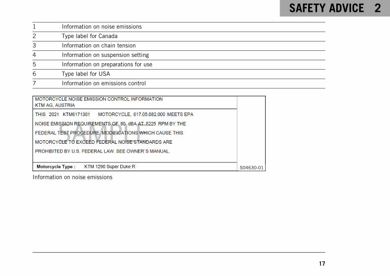
1 Information on noise emissions
2 Type label for Canada
3 Information on chain tension
4 Information on suspension setting
5 Information on preparations for use
6 Type label for USA
7 Information on emissions control
S04630-01
Information on noise emissions

2 SAFETY ADVICE
18
S04629-01
Type label for Canada
L01472-01
Information on chain tension

SAFETY ADVICE 2
19
S04099-01
Information on suspension setting
F00491-01
Information on preparations for use

2 SAFETY ADVICE
20
S04631-01
Type label for USA
S04628-01
Information on emissions control

SAFETY ADVICE 2
21
2.6 Reporting safety defects
If you believe that your vehicle has a defect which could cause an accident resulting in injury or death, youshould immediately inform the National Highway Traffic Safety Administration (NHTSA) in addition to notifyingKTM North America, Inc.If NHTSA receives multiple similar complaints, it may open an investigation, and if it finds that a safety defectexists in a group of vehicles, it may order a recall and remedy campaign. However, NHTSA cannot becomeinvolved in individual problems between you, your dealer, or KTM North America, Inc.To contact NHTSA, you may either call the Auto Safety Hotline toll-free at 1–888–327–4236 or visit the websitewww.nhtsa.dot.gov, or write to: NHTSA Headquarters, 1200 New Jersey Avenue, SE, West Building, Washington,DC 20590. You can also obtain other information about motor vehicle safety from the Hotline.
2.7 Noise emission warranty
KTM warrants that this exhaust system, at the time of sale, meets all applicable U.S. EPA Federal noise stan-dards.This manufacturer’s warranty extends to the first person who purchases this exhaust system for purposes otherthan resale, and to all subsequent buyers.Warranty claims should be directed to:KTM North America, Inc., Customer Support, 1119 Milan Ave., Amherst, OH 44001, USAPhone: (440) 985-3553www.ktmusa.comKTM Canada, Inc., Customer Support, 8701 Rue Samuel‑Hatt, Chambly, QC J3L 6V4, CanadaPhone: (450) 441-4451www.ktmcanada.com

2 SAFETY ADVICE
22
2.8 Operating noise warning
This product should be checked for necessary repair or replacement parts if the motorcycle noise has increasedsignificantly through use. Otherwise, the owner may become subject to penalties under the applicable ordinances.
2.9 Manufacturer warranty for the exhaust monitoring system
KTM North America, Inc. guarantees that, at the time of sale, the exhaust monitoring system complies with allthe standards of the US Environmental Protection Agency (EPA) and the California Air Resources Board (CARB).This manufacturer warranty applies in respect of the first owner of the motorcycle and all subsequent owners.Your exhaust monitoring system may include parts, such as the fuel injection system, ignition, catalytic converter,control units, hoses, connectors and other emission related assemblies, fuel tank, crankcase breather, fuel tanklid for vehicles with fuel evaporation monitoring, oil filler cap, pressure control valve, fuel/vapor separator, canis-ter, ignition coils, ignition wire, capacitors, and spark plugs, if a fault occurs before the first scheduled replace-ment and includes the hoses, fittings, and pipes that are used directly in these components.If the warranty conditions are met, KTM will repair your motorcycle for you free of charge, including diagnosis,parts, and labor.As the owner of the motorcycle, you are responsible for the required maintenance specified in the Owner's Man-ual.Please note that KTM is entitled to reject warranty claims if your motorcycle or a part fails due to misuse, neg-ligence, an accident, participation in racing or similar events, improper maintenance or unauthorized modifica-tions.
Scope of the manufacturer’s warranty– Five (5) years or 30,000 kilometers (18,641 miles), whichever occurs first.
If you have any questions regarding the manufacturer warranty for the exhaust monitoring system, please addressthese to:KTM North America, Inc., Customer Support, 1119 Milan Ave., Amherst, OH 44001, USA

SAFETY ADVICE 2
23
Phone: (888) 985-6090U.S. Environmental Protection Agency, 2000 Traverwood Drive, Ann Arbor, MI 48105, USACalifornia Air Resources Board, 1001 "I" Street, Sacramento, CA 95814, USA
2.10 Consumer rights
Warranty claims must be submitted to an authorized KTM workshop. If you are not satisfied, please contact:KTM North America, Inc., Customer Support, 1119 Milan Ave., Amherst, OH 44001, USAPhone: (440) 985-3553www.ktmusa.comKTM Canada, Inc., Customer Support, 8701 Rue Samuel‑Hatt, Chambly, QC J3L 6V4, CanadaPhone: (450) 441-4451www.ktmcanada.comDifferent rights may apply, according to national or regional legislation.
2.11 Tampering warning
Tampering with the noise control system is prohibited. Federal law prohibits the following acts or the causingthereof:
1 The removal or rendering inoperative by any person other than for purposes of servicing, repair, or replace-ment, of any device or element of design incorporated into any new vehicle for the purpose of noise controlprior to its sale or delivery to the ultimate purchaser or while it is in use, or
2 the use of the vehicle after such device or element of design has been removed or rendered inoperative by anyperson.
Among those acts presumed to constitute tampering are the acts listed below:

2 SAFETY ADVICE
24
1 Removal or puncturing of the main silencers, baffles, header pipes or any other components which conductexhaust gases.
2 Removal or puncturing of parts of the intake system.
3 Lack of proper maintenance.
4 Replacing moving parts of the vehicle, or parts of the exhaust system or intake system, with parts other thanthose specified by the manufacturer.
2.12 Safe operation
DangerDanger of accidents A rider who is not fit to ride poses a danger to him or herself and others.
– Do not operate the vehicle if you are not fit to ride due to alcohol, drugs or medication.
– Do not operate the vehicle if you are physically or mentally impaired.
DangerDanger of poisoning Exhaust gases are toxic and inhaling them may result in unconsciousness and death.
– Always make sure there is sufficient ventilation when running the engine.
– Use effective exhaust extraction when starting or running the engine in an enclosed space.

SAFETY ADVICE 2
25
WarningDanger of burns Some vehicle components become very hot when the vehicle is operated.
– Do not touch any parts such as the exhaust system, radiator, engine, shock absorber, or brake systembefore the vehicle parts have cooled down.
– Let the vehicle parts cool down before you perform any work on the vehicle.
Only operate the vehicle when it is in perfect technical condition, in accordance with its intended use, and in asafe and environmentally compatible manner.The vehicle should only be used by trained persons. An appropriate driver's license is needed to ride the vehicleon public roads.Have malfunctions that impair safety promptly eliminated by an authorized KTM workshop.Adhere to the information and warning labels on the vehicle.
2.13 Protective clothing
WarningRisk of injury Missing or poor protective clothing presents an increased safety risk.
– Wear appropriate protective clothing such as helmet, boots, gloves as well as trousers and a jacketwith protectors on all rides.
– Always wear protective clothing that is in good condition and meets the legal regulations.
In the interest of your own safety, KTM recommends that you only operate the vehicle while wearing protectiveclothing.

2 SAFETY ADVICE
26
2.14 Work rules
Unless specified otherwise, the ignition must be turned off during all work (models with ignition lock, modelswith remote key) or the engine must be at a standstill (models without ignition lock or remote key).Special tools are necessary for certain tasks. The tools are not a component of the vehicle, but can be orderedusing the number in parentheses. Example: bearing puller (15112017000)During assembly, use new parts to replace parts which cannot be reused (e.g. self-locking screws and nuts,expansion screws, seals, sealing rings, O-rings, pins, and lock washers).In the case of certain screws, a screw adhesive (e.g., Loctite®) is required. Observe the manufacturer's instruc-tions.If a screw adhesive (e.g., Precote®) has already been applied to a new part, do not apply any additional threadlocker.After disassembly, clean the parts that are to be reused and check them for damage and wear. Change damagedor worn parts.After completing a repair or service work, check the operating safety of the vehicle.
2.15 Environment
If you use your motorcycle responsibly, you can ensure that problems and conflicts do not occur. To protect thefuture of the motorcycle sport, make sure that you use your motorcycle legally, display environmental conscious-ness, and respect the rights of others.When disposing of used oil, other operating and auxiliary fluids, and used components, comply with the laws andregulations of the respective country.Because motorcycles are not subject to the EU regulations governing the disposal of used vehicles, there are nolegal regulations that pertain to the disposal of an end-of-life motorcycle. Your authorized KTM dealer will be gladto advise you.

SAFETY ADVICE 2
27
2.16 Owner's Manual
Read this owner's manual carefully and completely before making your first trip. The Owner's Manual containsuseful information and many tips on how to operate, handle, and service your motorcycle. This is the only way tofind out how best to customize the vehicle for your own use and how you can protect yourself from injury.
TipStore the Owner's Manual on your terminal device, for example, so that you can read it whenever you needto.
If you would like to know more about the vehicle or have questions on the material you read, please contact anauthorized KTM dealer.The Owner's Manual is an important component of the vehicle. If the vehicle is sold, the Owner's Manual must bedownloaded again by the new owner.The Owner's Manual can be downloaded several times using the QR code or the link on the delivery certificate.
The Owner's Manual is also available for download from your authorized KTM dealer and on the KTM website. Aprinted copy can also be ordered from your authorized KTM dealer.International KTM Website: http://www.ktm.com
3 IMPORTANT NOTES
28
3.1 Manufacturer warranty, implied warranty
The work prescribed in the service schedule must only be carried out in an authorized KTM workshop and con-firmed in the KTM Dealer.net, as otherwise all warranty claims will be void. Damage or secondary damage causedby tampering with and/or conversions on the vehicle are not covered by the manufacturer warranty.
3.2 Fuel, auxiliary substances
NoteEnvironmental hazard Improper handling of fuel is a danger to the environment.
– Do not allow fuel to enter the groundwater, the soil, or the sewage system.
Use fuels and auxiliary substances in accordance with the Owner's Manual and specification.
3.3 Spare parts, accessories
For your own safety, only use spare parts and accessory products that are approved and/or recommended by KTMand have them installed by an authorized KTM workshop. KTM accepts no liability for other products and anyresulting damage or loss.Certain spare parts and accessory products are specified in parentheses in the descriptions. Your authorized KTMdealer will be glad to advise you.
The current KTM PowerParts for your vehicle can be found on the KTM website.International KTM Website: http://www.ktm.com

IMPORTANT NOTES 3
29
3.4 Service
A prerequisite for perfect operation and prevention of premature wear is that the service, care, and tuning workon the engine and chassis is properly carried out as described in the Owner's Manual. An incorrect suspensionsetting can lead to damage and breakage of chassis components.Use of the vehicle under difficult conditions, such as dusty environments, heavy rain, high heat or with a heavyload, can lead to considerably more rapid wear of components such as the air filter, drive train, brake system, orsuspension components. For this reason, it may be necessary to inspect or replace parts before the next sched-uled service.It is imperative that you adhere to the stipulated run-in times and service intervals. If you observe these exactly,you will ensure a much longer service life for your motorcycle.The relevant mileage or time interval is whichever occurs first.
3.5 Figures
The figures contained in the manual may depict special equipment.In the interest of clarity, some components may be shown disassembled or may not be shown at all. It is notalways necessary to disassemble the component to perform the activity in question. Please follow the instructionsin the text.
3.6 Customer service
Your authorized KTM dealer will be happy to answer any questions you may have on your vehicle and KTM.
A list of authorized KTM dealers can be found on the KTM website.International KTM Website: http://www.ktm.com

4 VIEW OF VEHICLE
30
4.1 View of vehicle, front left (example)
S03093-10

VIEW OF VEHICLE 4
31
1 Clutch lever ( p. 38)
2 Supporting strap ( p. 58)
3 Tool set ( p. 57)
4 Seat lock ( p. 57)
5 Passenger foot pegs ( p. 58)
6 Rider footrests
7 Shift lever ( p. 59)
8 Side stand ( p. 60)
9 Cooling system compensating tank
bk Engine oil level viewer

4 VIEW OF VEHICLE
32
4.2 View of vehicle, rear right (example)
S03094-10

VIEW OF VEHICLE 4
33
1 Fuel tank filler cap
2 Combination switch, left side ( p. 39)
3 Start button/emergency OFF switch ( p. 49)
3 RACE-ON button ( p. 50)
3 Hazard warning flasher switch ( p. 48)
4 Throttle grip ( p. 39)
5 Hand brake lever ( p. 38)
6 Fork rebound adjustment
7 Fork compression adjuster
8 Foot brake lever ( p. 60)
9 Compression damping of the shock absorber ( p. 195)
bk Shock absorber rebound damping

5 SERIAL NUMBERS
34
5.1 Vehicle identification number
402324-10
The vehicle identification number1 is stamped on the right sideof the steering head.The vehicle identification number is also shown on the type label.
5.2 Type label
402174-10
The type label for the USA1 is located on the steering head.

SERIAL NUMBERS 5
35
402293-10
The Canada type label1 is located on the frame on the left.
5.3 Key number
F01249-10
The key number Code number1 can be found onthe KEYCODECARD.
InfoYou need the key number to order a spare key. Keepthe KEYCODECARD in a safe place.

5 SERIAL NUMBERS
36
5.4 Engine number
402296-10
The engine number1 is stamped on the right side of the engine.
5.5 Fork part number
402295-10
The fork part number1 is stamped on the inside of the axleclamp.

SERIAL NUMBERS 5
37
5.6 Shock absorber article number
402798-10
The shock absorber article number1 is stamped on the top ofthe shock absorber above the adjusting ring towards the engineside.
5.7 Steering damper article number
H01060-10
Steering damper item number1 is embossed on the undersideof the steering damper.

6 CONTROLS
38
6.1 Clutch lever
S03879-10
Clutch lever1 is fitted on the handlebar on the left.The clutch is activated hydraulically and adjusts itself automati-cally.
6.2 Hand brake lever
S03880-10
The hand brake lever1 is fitted on the right side of the handle-bar.The front brake is engaged using the hand brake lever.
CONTROLS 6
39
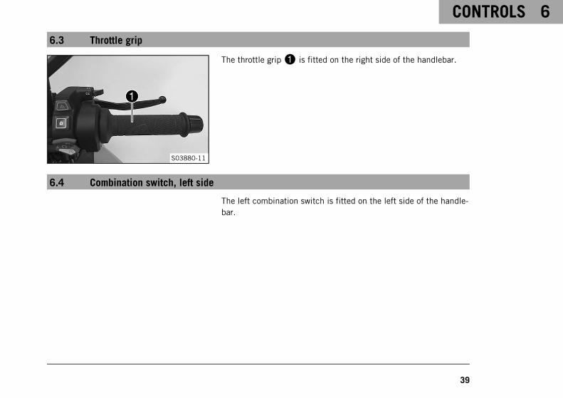
6.3 Throttle grip
S03880-11
The throttle grip1 is fitted on the right side of the handlebar.
6.4 Combination switch, left side
The left combination switch is fitted on the left side of the handle-bar.

6 CONTROLS
40
S03881-10
Overview of the left combination switch
1 Light switch ( p. 40)
2 Cruise control buttons ( p. 43)
3 Menu buttons ( p. 41)
4 Turn signal switch ( p. 42)
5 Horn button ( p. 43)
6 +RES/-SET button ( p. 46)
6.5 Light switch
S03882-10
The light switch1 is fitted on the combination switch on theleft.
Possible states
Low beam on – Light switch in positionA. In thisposition, the low beam and the tail light are switchedon.
High beam on – Light switch in positionB. In thisposition, the high beam and the tail light are switchedon.

CONTROLS 6
41
Headlight flasher – Light switch in positionC. Theheadlight flasher is operated in this position. The lightswitch returns automatically to the positionA afteruse.
6.6 Menu buttons
S03881-11
The menu buttons are fitted in the middle of the left combinationswitch.The menu buttons are used to control the display on the combina-tion instrument.Button1 is the UP button.Button2 is the RIGHT button.Button3 is the DOWN button.Button4 is the LEFT button.Button5 is the ENTER button.Button6 is the BACK button.

6 CONTROLS
42
6.7 Turn signal switch
S03881-12
Turn signal switch1 is fitted on the combination switch on theleft.
Possible states
Turn signal off – Turn signal switch pushed toward theswitch housing.
Left turn signal, on – Turn signal switch pressed tothe left. The turn signal switch returns automaticallyto the central position after use.
Right turn signal, on – Turn signal switch pressed tothe right. The turn signal switch returns automaticallyto the central position after use.
InfoAn automatic turn signal switch-off function (ATIR) is avail-able as a software feature.The ATIR function uses a time and distance counter.If the turn signal has been on for at least 10 seconds and150 meters of riding distance, the turn signal is switchedoff.If the vehicle is stationary, both counters are stopped.If the turn signal switch is reactivated, both counters arereset.

CONTROLS 6
43
6.8 Horn button
S03881-13
Horn button1 is fitted on the left side of the handlebar.
Possible states• The horn button is in the basic position• The horn button is pressed – The horn is operated in this
position.
6.9 Cruise control buttons
S03881-14
The cruise control buttons1,2 and3 of the are located onthe left side of the combination switch.
Possible states• Cruise control system button in the basic position.• Button +RES is pressed briefly. – The last saved speed is
reapplied. Every subsequent brief pressing increases the tar-get speed by 1 km/h or 1 mph.
• Button +RES is pressed and held. – The target speedincreases in increments of 5 km/h or 5 mph.

6 CONTROLS
44
• Button ‑SET is pressed. – The cruise control system functionis activated and the current speed is maintained. Every sub-sequent brief press reduces the target speed by 1 km/h or1 mph.
• Button ‑SET is pressed and held. – The target speeddecreases in increments of 5 km/h or 5 mph.
InfoAfter activation of the cruise control system function, thethrottle grip can be turned back to the basic position. Theselected speed will be maintained.If no target speed has yet been saved, this can be savedonce using the +RES button.If the target speed is exceeded for less than 30 seconds byturning the throttle grip, the cruise control system remainsactivated.
To switch off the cruise control system function press the cruisecontrol system button again.In addition, the cruise control system function is deactivated whenone of the following events occurs:
– Operating the hand brake lever
– Operating the foot brake lever
– Operating the clutch lever
– Gear change without quickshifter+
– Turning the throttle grip beyond the basic position

CONTROLS 6
45
– Control of the motorcycle traction control (MTC)
– Slip at the rear wheel or lifting front wheel
– A fault occurring, which impairs the cruise control systemfunction
– Exceeding the target speed for more than 30 seconds whenovertaking
WarningDanger of accidents The cruise control system function isnot suitable for all riding situations.
The selected target speed will not be reached, if theengine power is not sufficient for a gradient.The selected target speed will be exceeded if the enginebraking effect is not sufficient on an incline.
– Do not use the cruise control systems function onwinding roads.
– Do not use the cruise control systems on slippery roadsurfaces (e.g. rain, ice or snow), where there is poorvisibility or on unpaved surfaces (e.g. sand, stones orgravel).
– Do not use the cruise control systems function if thetraffic does not permit a constant speed.

6 CONTROLS
46
The cruise control system function is only available when motorcy-cle traction control (MTC) is activated.When motorcycle traction control (MTC) is switched off, the cruisecontrol system function is also switched off.The cruise control system function cannot be activated duringrapid acceleration.The cruise control system function can only be activated in third,fourth, fifth and sixth-gear.The control range is from 40 to 200 km/h or from 25 to 125 mph.
6.10 +RES/-SET button
S03881-15
The +RES button1 is fitted on the handlebar, front left.The ‑SET button2 is fitted on the handlebar, rear left.
InfoThe +RES and ‑SET buttons are used to control the cruisecontrol system when the cruise control function is acti-vated.If the cruise control function is disabled and the ridingmode Performance or Track is set, the +RES and ‑SET but-tons are used to adjust the Slip Adjuster.

CONTROLS 6
47
6.11 Combination switch, right
The right combination switch is fitted on the right side of the han-dlebar.
S03883-11
Overview of the right combination switch
1 C1 and C2 switch ( p. 51)
2 Hazard warning flasher switch ( p. 48)
3 RACE-ON button ( p. 50)
4 Start button/emergency OFF switch ( p. 49)

6 CONTROLS
48
6.12 Hazard warning flasher switch
S03883-12
The hazard warning flasher switch1 is fitted on the right side ofthe combination switch.The hazard warning flasher is used to indicate emergency situa-tions.
InfoThe hazard warning flasher can be activated or deactivatedwhile the ignition is switched on or up to 60 seconds afterthe ignition is switched off.Only keep the hazard warning flasher activated as long asnecessary as it depletes the 12-V battery.
Possible states
Hazard warning flasher on – All four turn signals andthe green turn signal indicator lights in the combina-tion instrument flash.

CONTROLS 6
49
6.13 Start button/emergency OFF switch
S03883-14
The start button/emergency OFF switch1 is fitted on the rightside of the combination switch.
Possible states
Start button/emergency OFF switch off (upper posi-tion) – In this position, the ignition circuit is inter-rupted, a running engine stops, and a non-runningengine cannot be started. A message appears on thedisplay.
Start button/emergency OFF switch on (middle posi-tion) – This position is required for operation; the igni-tion circuit is closed.
Starter motor on (lower position) – In this position, thestarter motor is actuated.

6 CONTROLS
50
6.14 RACE-ON button
S03883-13
The RACE-ON button1 is fitted on the right side of the combi-nation switch.
InfoThe RACE-ON button performs the ignition lock function onthis vehicle.The steering can only be locked if the handlebar is turnedto the left.
Possible states• RACE-ON button in the basic position.• RACE-ON button pressed briefly – Pressing briefly switches
the ignition on and unlocks the steering lock or switches theignition off. The RACE-ON indicator lamp lights up brieflyonce for confirmation.
• RACE-ON button pressed and held – Pressing and holdingswitches the ignition off and locks the steering lock.

CONTROLS 6
51
6.15 C1 and C2 switch
S03884-10
The C1 and C2 switch is fitted on the right of the combinationswitch.
InfoThe C1 and C2 switch enables quick access to variousmenus.The C1 and C2 switch can be freely configured.
6.16 Steering lock (antenna)
S03885-10
On this vehicle, the ignition/steering lock is replaced by a remotekey with transponder (RACE-ON key ( p. 53)).In order to activate the steering lock, the handlebar must beturned fully to the left.The steering is locked and unlocked electromechanically via theRACE-ON button ( p. 50).If the battery voltage of the RACE-ON key is too low, place eitherthe RACE-ON key or the black ignition key in areaA and repeatstarting.

6 CONTROLS
52
InfoStore the ignition key safely again as soon as the enginehas been started.
Possible states• Ignition off, steering locked – In this operating mode, the
ignition circuit is interrupted and the steering locked.• Ignition off, steering unlocked – In this operating mode, the
ignition circuit is interrupted and the steering unlocked.• Ignition on, steering unlocked – In this operating mode, the
ignition circuit is closed and the steering unlocked.
6.17 Immobilizer
S03841-10
The electronic immobilizer secures the vehicle against unautho-rized use.The immobilizer is activated and the engine electronics are lockedas soon as the ignition is switched off via the RACE-ON button( p. 50).The RACE-ON indicator lamp1 can indicate errors by flashing.If the optional alarm system is installed, the RACE-ON indicatorlamp1 flashes when the ignition is switched off and the alarmsystem is switched on.

CONTROLS 6
53
6.18 RACE-ON key
S01724-10
In this vehicle, the RACE-ON key1 performs all the functions ofthe conventional ignition key.Press the2 button to fold out the key bit. The key bit it isonly used for unlocking the seat lock and for opening the cases(optional).The black ignition key3 is only intended for situations in whichthe RACE-ON key is not available or is not functional.The black ignition key can be used to start the vehicle if theRACE-ON key battery voltage is too low and the transponder is notrecognized by the vehicle. The black Race-on key can also be usedto unlock the seat lock and open the cases (optional).
InfoThe ignition keys contain electronic components. Alwaysmaintain a distance of several centimeters to other deviceswith electronic components.
A lost ignition key must be deactivated by an authorized KTMworkshop to prevent unauthorized persons from operating the vehi-cle.The ignition keys supplied are activated when delivered.Up to four ignition keys in total can be activated by an authorizedKTM workshop. The key number must be provided in each case.

6 CONTROLS
54
6.19 Opening fuel tank filler cap
DangerFire hazard Fuel is highly flammable.
The fuel in the fuel tank expands when warm and can escape if overfilled.
– Do not fuel the vehicle in the vicinity of open flames or lit cigarettes.
– Switch off the engine for refueling.
– Make sure that no fuel is spilled; particularly not on hot parts of the vehicle.
– If any fuel is spilled, wipe it off immediately.
– Observe the specifications for refueling.
WarningDanger of poisoning Fuel is poisonous and a health hazard.
– Avoid skin, eye and clothing contact with fuel.
– Immediately consult a doctor if you swallow fuel.
– Do not inhale fuel vapors.
– In case of skin contact, rinse the affected area with plenty of water.
– Rinse the eyes thoroughly with water, and consult a doctor in case of fuel contact with the eyes.
– Change your clothing in case of fuel spills on them.
– Keep fuels correctly in a suitable canister, and out of the reach of children.

CONTROLS 6
55
NoteEnvironmental hazard Improper handling of fuel is a danger to the environment.
– Do not allow fuel to enter the groundwater, the soil, or the sewage system.
ConditionThe motorcycle is stationary.The engine is switched off.The ignition has been switched on or off for less than 1 minute.
S03886-10
– Fold up cover1 slowly.
The fuel tank filler cap is unlocked.
– Fold up fuel tank filler cap2.

6 CONTROLS
56
6.20 Closing the fuel tank filler cap
S03886-11
WarningFire hazard Fuel is highly flammable, toxic and ahealth hazard.
– Check that the fuel tank filler cap is locked cor-rectly after closing.
– Change your clothing if fuel spills on them.
– Rinse the affected area immediately with plenty ofwater in the event of contact with the skin.
– Fold down fuel tank filler cap1 and push it down.
The fuel tank filler cap locks audibly in place.

CONTROLS 6
57
6.21 Seat lock
S03887-10
Seat lock1 is located on the left side of the vehicle under theseat.It can be unlocked using the RACE-ON key or the black ignitionkey.
6.22 Tool set
S03888-10
The tool set1 is located under the passenger seat.

6 CONTROLS
58
6.23 Supporting strap
S03889-10
Supporting strap1 is attached underneath the passenger seat.
InfoIf the supporting strap is not needed, it can be stowedunderneath the pillion bench.
The supporting strap is provided for the passenger to hold on to.
6.24 Passenger foot pegs
S03890-01
The passenger foot pegs can be folded up and down.
Possible states• Passenger foot pegs folded up – For operation without a pas-
senger.• Passenger foot pegs folded down – For operation with a pas-
senger.

CONTROLS 6
59
6.25 Shift lever
402299-10
The shift lever1 is fitted on the left side of the engine.
402299-11
The gear positions can be seen in the figure.The idle position is between first and second gears.

6 CONTROLS
60
6.26 Foot brake lever
402301-10
Foot brake lever1 is located in front of the right footrest.The rear brake is engaged with the foot brake lever.
6.27 Side stand
402029-10
Side stand1 is located on the left of the vehicle.The side stand is used for parking the motorcycle.
InfoThe side stand must be folded up during motorcycle use.The side stand is coupled with the safety starting system;see the instructions in the "Stopping, parking" chapter.
Possible states• Side stand folded out – The vehicle can be supported on the
side stand. The safety starting system is active.

CONTROLS 6
61
• Side stand folded in – This position is mandatory when ridingthe motorcycle. The safety starting system is inactive.

7 COMBINATION INSTRUMENT
62
7.1 Combination instrument
S03758-10

COMBINATION INSTRUMENT 7
63
The combination instrument is attached in front of the handlebar.The combination instrument is divided into two function areas.
1 indicator lamps ( p. 68)Display2
7.2 Activation and test
S03842-01
ActivationThe combination instrument is activated when the ignition isswitched on.
InfoThe brightness of the displays is controlled by an ambientlight sensor in the combination instrument.
TestThe welcome sequence appears on the display and the indicatorlamps are briefly activated for a function check.

7 COMBINATION INSTRUMENT
64
InfoThe malfunction indicator lamp always lights up as long asthe engine is not running. If the engine is running and themalfunction indicator lamp lights up, stop (taking care notto endanger yourself or other road users in the process) andcontact an authorized KTM workshop.The oil pressure warning lamp always lights up as long asthe engine is not running. If the engine is running and theoil pressure warning lamp lights up, stop immediately (tak-ing care not to endanger yourself or other road users in theprocess) and switch off the engine.The ABS warning lamp and TC indicator lamp light up untila speed of approx. 6 km/h (approx. 4 mph) or more hasbeen reached.

COMBINATION INSTRUMENT 7
65
7.3 Day-night mode
S03748-01
Day mode is shown in a bright color.
S03749-01
Night mode is shown in a dark color.
InfoThe ambient light sensor in the combination instrumentmeasures the brightness of the environment and automat-ically switches the display to day or night mode. The dis-play is brightened, darkened or switched to the other modedepending on the brightness measured by the ambient lightsensor.In the Display Theme menu, the display mode can bechanged manually between AUTOMATICand NIGHT.
7 COMBINATION INSTRUMENT
66
7.4 Warnings
S03763-01
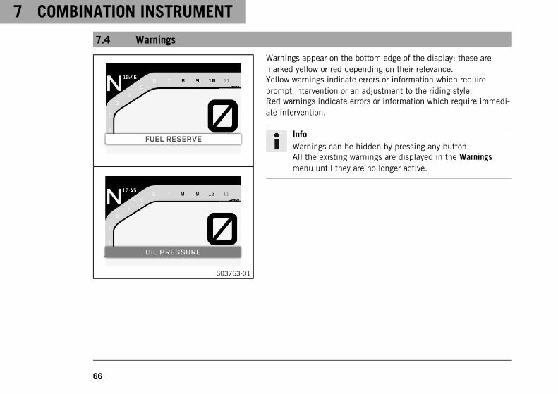
Warnings appear on the bottom edge of the display; these aremarked yellow or red depending on their relevance.Yellow warnings indicate errors or information which requireprompt intervention or an adjustment to the riding style.Red warnings indicate errors or information which require immedi-ate intervention.
InfoWarnings can be hidden by pressing any button.All the existing warnings are displayed in the Warningsmenu until they are no longer active.

COMBINATION INSTRUMENT 7
67
7.5 Ice warning
S03767-10
The ice warning goes on when there is an increased risk of iceon the roads.The ice warning is shown in area1 of the display.The ice warning appears on the display when the ambient tem-perature drops below the specified value.
Temperature 4 °C (39 °F)
The ice warning goes out on the display when the ambient tem-perature rises above the specified value again.
Temperature 6 °C (43 °F)
InfoWhen the ice warning lights up, the warning ICE WARN-ING also appears.

7 COMBINATION INSTRUMENT
68
7.6 Indicator lamps
S03764-01

COMBINATION INSTRUMENT 7
69
The indicator lamps offer additional information about the operating state of the motorcycle.When the ignition is switched on, all indicator lamps light up briefly.
InfoThe malfunction indicator lamp always lights up as long as the engine is not running. If the engine is run-ning and the malfunction indicator lamp lights up, stop (taking care not to endanger yourself or other roadusers in the process) and contact an authorized KTM workshop.The oil pressure warning lamp always lights up as long as the engine is not running. If the engine is run-ning and the oil pressure warning lamp lights up, stop immediately (taking care not to endanger yourself orother road users in the process) and switch off the engine.The ABS warning lamp and TC indicator lamp light up until a speed of approx. 6 km/h (approx. 4 mph) ormore has been reached.
Possible states
RACE-ON indicator lamp lights up/flashes yellow/red – Status or error messages relating toRace-on system/alarm system.
The left turn signal indicator lamp flashes green with a steady rhythmic flash – The left turnsignal is switched on.
The high beam indicator lamp lights up blue – The high beam is switched on.
The general warning lamp lights up yellow – A note/warning note on operating safety has beendetected. This is also shown in the display.
The ABS warning lamp lights up yellow – Status or error messages relating to ABS. When ABSSupermoto mode is activated, SM is shown in the display.

7 COMBINATION INSTRUMENT
70
TC indicator lamp lights up/flashes yellow – The MTC ( p. 292) is not active, is currentlyintervening or a Launch Control Start is being executed. The TC indicator lamp also lights upif an error is detected. Contact an authorized KTM workshop. The TC indicator lamp flashes ifthe motorcycle traction control actively engages.
The oil pressure warning lamp lights up red – The oil pressure is too low. Stop immediately,taking care not to endanger yourself or other road users in the process, and switch off theengine.
The cruise control system indicator lamp lights up yellow – The cruise control system functionis switched on, but cruise control is not activated.
The cruise control system indicator lamp lights up green – The cruise control system functionis switched on and cruise control is activated.
Malfunction indicator lamp lights up yellow – The OBD has detected an error in the vehicleelectronics.
The right turn signal indicator lamp flashes green with a steady rhythmic flash – The right turnsignal is switched on.

COMBINATION INSTRUMENT 7
71

7 COMBINATION INSTRUMENT
72
7.7 Display
S03766-10

COMBINATION INSTRUMENT 7
73
InfoThe figure shows the start screen of the combination instrument. If the menu is opened, the speed is stilldisplayed.
1 Tachometer
1Shift warning light ( p. 82)
The shift warning light is integrated in the tachometer display.
2 Speed
3 Unit for the speedometer
4 Fuel level display ( p. 87)
5 ABS Mode display ( p. 84)
6 Ride Mode ( p. 291)
7 Gear display
8 Time ( p. 89)

7 COMBINATION INSTRUMENT
74
7.8 TRACK Display (optional)
S03768-10

COMBINATION INSTRUMENT 7
75
InfoThe figure shows the start screen of the combination instrument in active drive mode TRACK (optional). Ifthe menu is opened, the speed is still displayed.
1 Anti wheelie mode (optional) ( p. 293)
2 Launch Control (optional) ( p. 166)
3Slip adjustment (optional) ( p. 294)If the slip adjustment changes in the widget, this indicator is replaced by the slip adjustment indicator fora few seconds.

7 COMBINATION INSTRUMENT
76
7.9 Performance layout (optional)
S03769-10

COMBINATION INSTRUMENT 7
77
The figure shows the start screen of the combination instrument in active drive mode TRACK (optional) in the per-formance layout.In the performance layout, you can use KTM MY RIDE in TRACK mode (optional).If the menu is opened, the speed is still displayed.
7 COMBINATION INSTRUMENT
78
7.10 Small widget
S03785-01

COMBINATION INSTRUMENT 7
79
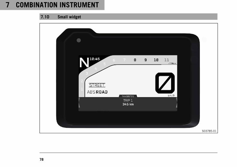
The figure shows the start screen of the combination instrument with the small widget opened.Information can be accessed in the small widget.

7 COMBINATION INSTRUMENT
80
7.11 Large widget
S03786-01

COMBINATION INSTRUMENT 7
81
The figure shows the start screen of the combination instrument with the large widget opened.Information can be accessed and configured in the large widget.
7.12 Odometer
S03757-01
The odometer can be displayed in the FAVORITES widget as Trip 1.To do this, the information must be configured in the widget.Information on the total distance covered can be accessed inthe General Info menu under menu item ODO or configured aswidget information.The Trip 1 menu displays further information.Information about other distances covered can be accessed inthe Trip 2menu.

7 COMBINATION INSTRUMENT
82
7.13 Engine speed
S03750-01
The engine speed is shown in area1 of the display.The engine speed is measured in revolutions per minute.
7.14 Shift warning light
S03751-01
The shift warning light is integrated in the tachometer display.In the Settings menu under Shift Light, the engine speed for theshift warning light can be set. The shift warning light is alwaysactive during the running-in phase (up to 1,000 km / 621 mi).The shift warning light can only be deactivated, and the values forRPM 1 and RPM 2 can only be adjusted after this. The shift warn-ing light flashes slowly at RPM 1 and flashes quickly at RPM 2.
InfoIn sixth-gear, the shift warning light is deactivated whenthe engine is warm after the first service.

COMBINATION INSTRUMENT 7
83
Coolant temperature ≤ 35 °C (≤ 95 °F)
ODO < 1,000 km (< 620 mi)
The shift warninglight always lights upat
6,500 rpm
Coolant temperature > 35 °C (> 95 °F)
ODO > 1,000 km (> 620 mi)
RPM 1 shift warninglight
flashes slowly
RPM 2 shift warninglight
flashes quickly
7.15 Cruise control indicator
S03770-10
The operating state and active cruise control are shown in the1area of the display.Cruise control is operated using the cruise control buttons( p. 43).

7 COMBINATION INSTRUMENT
84
7.16 Speed
S03771-10
The speed is shown in area1 of the display.The unit of speed can be configured in the Settings menuunder UNITS.Speed is shown in kilometers per hour km/h or in miles perhour mph.
7.17 ABS Mode display
S03772-10
The ABS mode setting is shown in the1 area of the display.In the menu Motorcycle, the ABS can be configured underABS Mode.

COMBINATION INSTRUMENT 7
85
7.18 Ride display
S03774-10
The riding mode ( p. 291) setting is shown in area1 of thedisplay.The riding mode can be configured in the menu Ride Mode.
7.19 Gear display
S03775-10
The current gear is shown in area1 of the display.
7 COMBINATION INSTRUMENT
86
7.20 Heated grip (optional)
S03776-10
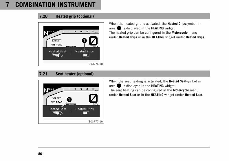
When the heated grip is activated, the Heated Gripssymbol inarea1 is displayed in the HEATING widget.The heated grip can be configured in the Motorcycle menuunder Heated Grips or in the HEATING widget under Heated Grips.
7.21 Seat heater (optional)
S03777-10
When the seat heating is activated, the Heated Seatsymbol inarea1 is displayed in the HEATING widget.The seat heating can be configured in the Motorcycle menuunder Heated Seat or in the HEATING widget under Heated Seat.

COMBINATION INSTRUMENT 7
87
7.22 Coolant temperature indicator
S03778-11
The coolant temperature indicator consists of bars. The more barsthat light up, the hotter the coolant.
InfoWhen all the bars flash, the warning ENGINE TEMP HIGHalso appears.
Possible states• The engine is cold – None of the eight bars light up.• Engine warm – Four bars light up.• Engine hot – Five to eight bars light up.• Engine very hot – all eight bars flash red.
7.23 Fuel level display
S03779-10
The fuel tank contents are shown in area1 of the display.The fuel level indicator consists of bars. The more bars are lit, themore fuel is in the fuel tank.

7 COMBINATION INSTRUMENT
88
InfoIf the fuel level is getting low, a bar flashes red and thefollowing warning LOW FUEL also appears.The fuel level is displayed with a slight delay to prevent theindicator from constantly moving while riding.The fuel level display is not updated while the side stand isfolded out or the emergency off switch is switched off.Once the side stand is folded up and the emergency OFFswitch is switched on, the fuel level display is next updatedafter 2 minutes.The fuel level display flashes if the combination instrumentdoes not receive a signal from the fuel level sensor.
7.24 Ambient air temperature indicator
S03780-10
The large INFO widget displays the ambient air temperature inarea1.The units of the ambient temperature can be configured inthe Settings menu under Units.The ambient air temperature is displayed in °C or °F.

COMBINATION INSTRUMENT 7
89
7.25 Time
S03781-10
The time is shown in area1 of the display.The time can be displayed in 24-hour format or 12-hour format inall languages.The time can be configured in the Settings menu under Clock/Date
InfoThe time must be set if the power supply has been inter-rupted.
7.26 Favourites display
S03782-10
A range of information can be configured in the FAVORITES widget.Up to four pieces of information can be configured and displayedin the large FAVORITES widget.
InfoThe four pieces of information in the large widget are dis-played in the small widget.Each set of information is displayed on two lines.Each set of information can be freely stored to a selectedarea.

7 COMBINATION INSTRUMENT
90
7.27 Navigation display (optional)
S03783-10
The direction arrow, the distance to the next waypoint and thestreet name are displayed in the small NAVIGATION widget whenthe navigation function is activated.The large NAVIGATION widget also displays the arrival time and thedistance to the destination. The volume of the navigation can alsobe adjusted in the large widget.In the KTM MY RIDE menu under Navigation you can access infor-mation on navigation and adjust the volume.
InfoThe Audio function can be used with the navigation func-tion at the same time.An incoming call is visualized in a small window at the topof the combination instrument display when the navigationfunction is active.

COMBINATION INSTRUMENT 7
91
7.28 Menu
S03759-10
InfoPress the RIGHT button1 in the start screen to open themenu.Use the RIGHT button1, the LEFT button2,the DOWN button3, the UP button4 and theENTER button5 to navigate in the menu.Press the BACK button6 to close the current menu or themenu overview.
7.28.1 KTM MY RIDE (optional)
S03789-01
Condition• Function KTM MY RIDE (optional) activated.
• Bluetooth® is activated.
– Press the RIGHT button when the menu is closed.
– Press the UP or DOWN button until KTM MY RIDE is marked.
Press the RIGHT button to open the menu.
In KTM MY RIDE, an appropriate cellphone or headset can bepaired with the combination instrument via Bluetooth® and thenavigation function can be configured.

7 COMBINATION INSTRUMENT
92
InfoNot every cellphone and headset is suitable for pairing withthe combination instrument.The standard Bluetooth® 2.1 must be supported.
7.28.2 Audio (optional)
S03790-01
Condition• Function KTM MY RIDE (optional) activated.
• Function Bluetooth® (optional) activated.
• The combination instrument is connected to a suitable cell-phone.
• The combination instrument is connected to a suitable Blue-tooth® headset.
• The cellphone music player is open.
– Press the RIGHT button when the menu is closed.
– Press the UP or DOWN button until KTM MY RIDE is marked.
Press the RIGHT button to open the menu.
WarningDanger of accidents Headphone volume which is toohigh distracts attention from traffic activity.
– Always select headphone volume which is lowenough for you to still clearly hear acoustic signals.

COMBINATION INSTRUMENT 7
93
– Press the UP or DOWN button until Audio is marked.
Press the RIGHT button to open the menu.
Press the UP button to increase the audio volume.
Press the DOWN button to reduce the audio volume.
Press the RIGHT button change to the next audio track.
Briefly pressing the LEFT button twice changes to the pre-vious audio title or plays the current audio title from thestart, depending on the cellphone model.
Press the ENTER button to play or pause the audio track.
TipWhen using a wired headset, the volume cannot be con-trolled via the combination instrument.With some cellphones, the audio player needs to bestarted before playback is possible.For easier operation, the Audio function can beassigned to the C1 or C2 button.

7 COMBINATION INSTRUMENT
94
7.28.3 Navigation (optional)
S03791-01
Condition• Function KTM MY RIDE (optional) activated.
• The KTM MY RIDE app (optional) is installed and opened on asuitable cellphone (Android devices Version 6.0 and higher,iOS devices Version 10 and higher).
• Function Bluetooth® (optional) activated.
• The combination instrument is connected to a suitable cell-phone.
• The GPS function is activated on the connected cellphone.
• For voice navigation: The combination instrument is connectedto a suitable headset and an appropriate language package hasbeen downloaded in the KTM MY RIDE app.
– Press the RIGHT button when the menu is closed.
– Press the UP or DOWN button until KTM MY RIDE is marked.
Press the RIGHT button to open the menu.
– Press the UP or DOWN button until Navigation is marked.
Press the RIGHT button to confirm the selection.
You can access navigation information and adjust the volume inthe menu Navigation.

COMBINATION INSTRUMENT 7
95
InfoThe route guidance is displayed in the small and large NAV-IGATION widget.The Audio function can be used with the navigation func-tion at the same time.An incoming call is visualized in a small window at the topof the combination instrument display when the navigationfunction is active.When the navigation function is switched on and the deviceis connected, the GPS symbol appears in the display of thecombination instrument.
7.28.4 Navigation information (optional)
S03793-01
Condition• Function KTM MY RIDE (optional) activated.
• The KTM MY RIDE app (optional) is installed and opened on asuitable cellphone (Android devices Version 6.0 and higher,iOS devices Version 10 and higher).
• Function Bluetooth® (optional) activated.
• The combination instrument is connected to a suitable cell-phone.
• The GPS function is activated on the connected cellphone.
– Press the RIGHT button when the menu is closed.
– Press the UP or DOWN button until KTM MY RIDE is marked.

7 COMBINATION INSTRUMENT
96
Press the RIGHT button to open the menu.
– Press the UP or DOWN button until Navigation is marked.
Press the RIGHT button to confirm the selection.
– Press the UP or DOWN button until Navigation Information ismarked.
Press the RIGHT button to open the menu.
InfoArrival Time shows the estimated arrival time of thecellphone.Distance to Target shows the distance to the destination.
Information on the current navigation can be viewed in the NAVI-GATION widget.
7.28.5 Volume (optional)
S03792-01
Condition• Function KTM MY RIDE (optional) activated.
• The KTM MY RIDE app (optional) is installed and opened on asuitable cellphone (Android devices Version 6.0 and higher,iOS devices Version 10 and higher).
• Function Bluetooth® (optional) activated.
• The combination instrument is connected to a suitable cell-phone.
• The GPS function is activated on the connected cellphone.

COMBINATION INSTRUMENT 7
97
• For voice navigation: The combination instrument is connectedto a suitable Bluetooth headset and an appropriate languagepackage has been downloaded in the KTM MY RIDE app.
– Press the RIGHT button when the menu is closed.
– Press the UP or DOWN button until KTM MY RIDE is marked.
Press the RIGHT button to open the menu.
– Press the UP or DOWN button until Navigation is marked.
Press the RIGHT button to confirm the selection.
WarningDanger of accidents Headphone volume which is toohigh distracts attention from traffic activity.
– Always select headphone volume which is lowenough for you to still clearly hear acoustic signals.
– Press the UP or DOWN button until Volume is marked.
Press the RIGHT button to open the menu.
– Press and hold the UP button in order to increase the volume.
– Press and hold the DOWN button in order to reduce the vol-ume.
The volume of the navigation can be set in thelarge NAVIGATION widget.

7 COMBINATION INSTRUMENT
98
7.28.6 Pairing (optional)
S03795-01
Condition• The motorcycle is stationary.
• Function KTM MY RIDE (optional) activated.
• Function Bluetooth® (optional) activated.
• The Bluetooth® function should also be activated in the deviceto be paired.
– Press the RIGHT button when the menu is closed.
– Press the UP or DOWN button until KTM MY RIDE is marked.
Press the RIGHT button to open the menu.
– Press the UP or DOWN button until Pairing is marked.
Press the RIGHT button to open the menu.
– Press the UP or DOWN button until the desired menuitem Phone or Headset is marked.
A suitable cellphone can be paired with the combinationinstrument in the Phone submenu.
A suitable headset can be paired with the combination instru-ment in the Headset submenu.
Press the RIGHT button to confirm the selection.

COMBINATION INSTRUMENT 7
99
InfoTwo cellphones can never be paired simultaneouslywith the combination instrument. Only one cellphoneand one headset per submenu item can be paired withthe combination instrument at the same time.If the headset type is set for a wired headset, no Blue-tooth®headset can be used.
– Press the UP or DOWN button until Pairing is marked.
– Press the RIGHT button to confirm the Pairing submenu item.
InfoWhen pairing the combination instrument to acellphone: A message appears on the combinationinstrument indicating that this is now ready for pairing.The pairing is completed successfully by confirmingthe Passkey on the cellphone and on the combinationinstrument using the ENTER button.When pairing the combination instrument to a headset:The registered trademark of the headset appears on thecombination instrument. By pressing the ENTER buttonthe device is selected, and confirmed with Confirm bypressing the ENTER button again. The pairing of a head-set with the combination instrument is now completedat this point.

7 COMBINATION INSTRUMENT
100
InfoWhen a suitable device has been successfully paired,the name of the paired cellphone or headset appears ineach case in the Phone or Headset menu.Not every cellphone or headset is suitable for pairingwith the combination instrument.
– If the device is in the range of the combination instrument andhas not been deleted previously while the Bluetooth® functionis active:
The device is automatically paired with the combinationinstrument.
If the device is not automatically paired with the combina-tion instrument after approx. 30 seconds:
– Restart combination instrument or Pairing repeat pro-cedure.
– To delete a paired device, press the UP or button DOWN untilthe paired device is highlighted.
– Open the delete Pairing menu by pressing the RIGHT buttonand confirm with the ENTER button.

COMBINATION INSTRUMENT 7
101
7.28.7 Telephony (optional)
S03796-01
Condition• Function KTM MY RIDE (optional) activated.
• Function Bluetooth® (optional) activated.
• The combination instrument is connected to a suitable cell-phone.
• The combination instrument is connected to a suitable head-set.
WarningDanger of accidents Headphone volume which is toohigh distracts attention from traffic activity.
– Always select headphone volume which is lowenough for you to still clearly hear acoustic signals.
– Press the RIGHT button to accept an incoming call.
– Press the LEFT button to reject an incoming call.
– Press and hold the UP button in order to increase the volume.
– Press and hold the DOWN button in order to reduce the vol-ume.
– Press the BACK button briefly to reduce the telephony display.

7 COMBINATION INSTRUMENT
102
InfoThe call duration and contact are displayed. Depend-ing on the cellphone settings, the contact is shown byname.When the telephony display is activated and reduced insize, a small window is displayed at the top edge of thecombination instrument display.An incoming call is visualized in a small window at thetop of the combination instrument display when thenavigation function is active.
7.28.8 Trip 1
S03798-01
– Press the RIGHT button when the menu is closed.
– Press the UP or DOWN button until Trips/Data is marked.
Press the RIGHT button to open the menu.
– Press the UP or DOWN button until Trip 1 is marked.
Press the RIGHT button to open the menu.
Trip 1 shows the distance since the last reset, such as between tworefueling stops. Trip 1 is running and counts up to 9999.ØFuelCons1 indicates the average fuel consumption basedon Trip 1.ØSpeed1 indicates the average speed based on Trip 1and Trip Time1.
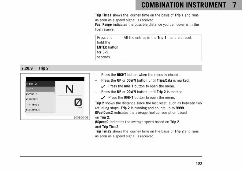
COMBINATION INSTRUMENT 7
103
Trip Time1 shows the journey time on the basis of Trip 1 and runsas soon as a speed signal is received.Fuel Range indicates the possible distance you can cover with thefuel reserve.
Press andhold theENTER buttonfor 3-5seconds.
All the entries in the Trip 1 menu are reset.
7.28.9 Trip 2
S03800-01
– Press the RIGHT button when the menu is closed.
– Press the UP or DOWN button until Trips/Data is marked.
Press the RIGHT button to open the menu.
– Press the UP or DOWN button until Trip 2 is marked.
Press the RIGHT button to open the menu.
Trip 2 shows the distance since the last reset, such as between tworefueling stops. Trip 2 is running and counts up to 9999.ØFuelCons2 indicates the average fuel consumption basedon Trip 2.ØSpeed2 indicates the average speed based on Trip 2and Trip Time2.Trip Time2 shows the journey time on the basis of Trip 2 and runsas soon as a speed signal is received.

7 COMBINATION INSTRUMENT
104
Fuel Range indicates the possible distance you can cover with thefuel reserve.
Press andhold theENTER buttonfor 3-5seconds.
All the entries in the Trip 2 menu are reset.
7.28.10 General Info
S03797-01
– Press the RIGHT button when the menu is closed.
– Press the UP or DOWN button until Trips/Data is marked.
Press the RIGHT button to open the menu.
– Press the UP or DOWN button until General Info is marked.
Press the RIGHT button to open the menu.
Date shows the date.ODO shows the total distance covered.Battery indicates the battery voltage.Oil Temp indicates the engine oil temperature.

COMBINATION INSTRUMENT 7
105
7.28.11 TPMS
S03801-01
Condition• Model with TPMS.
– Press the RIGHT button when the menu is closed.
– Press the UP or DOWN button until Trips/Data is marked.
Press the RIGHT button to open the menu.
WarningDanger of accidents The tire pressure monitoring sys-tem does not eliminate the necessity to check the tiresbefore going on a ride.
To avoid false alarms, the tire pressure values areevaluated over a period of several minutes.
– Check the tire pressure before every ride.
– Correct the tire pressure if the tire pressure devi-ates from the specified value.
– Even if the tire pressure values are correct, stopthe vehicle immediately if its behavior indicates aloss of pressure in the tires.
– Press the UP or DOWN button until TIRE AIR PRESSURE ismarked.

7 COMBINATION INSTRUMENT
106
Guideline
Tire pressure when solo
front: with cold tires 2.5 bar (36 psi)
rear: with cold tires 2.5 bar (36 psi)
Press the RIGHT button to open the menu.
The TIRE AIR PRESSURE menu displays the tire pressure of thefront and rear tires.PRESS FRONT indicates the tire pressure at the front.PRESS REAR indicates the tire pressure at the rear.
7.28.12 Warnings
S03802-01
Condition• Message or warning is present.
– Press the RIGHT button when the menu is closed.
– Press the UP or DOWN button until Trips/Data is marked.
Press the RIGHT button to open the menu.
– Press the UP or DOWN button until Warnings is marked.
Press the RIGHT button to open the menu.
– Use the UP or DOWN button to navigate through the warnings.
All the warnings that have occurred are displayed in the Warningsmenu.

COMBINATION INSTRUMENT 7
107
7.28.13 Service
S03803-01
– Press the RIGHT button when the menu is closed.
– Press the UP or DOWN button until Trips/Data is marked.
Press the RIGHT button to open the menu.
– Press the UP or DOWN button until Service is marked.
Press the RIGHT button to open the menu.
The next service due is shown in the Service menu.
7.28.14 Extra Functions
S03804-01
– Press the RIGHT button when the menu is closed.
– Press the UP or DOWN button until Trips/Data is marked.
Press the RIGHT button to open the menu.
– Press the UP or DOWN button until Extra Functions is marked.
Press the RIGHT button to open the menu.
– Use the UP or DOWN button to navigate through the extra func-tions.
The optional extra functions are listed in Extra Functions.

7 COMBINATION INSTRUMENT
108
InfoThe current KTM PowerParts and available software arelisted on the KTM website.
7.28.15 Ride Mode
S03808-01
– Press the RIGHT button when the menu is closed.
– Press the UP or DOWN button until the Ride Mode menu ismarked on the display.
Press RIGHT button to open the menu.
– Use the UP or DOWN button to navigate through the menu.
– Press the ENTER button to select engine and motorcycle trac-tion control settings that are coordinated with each other.
Guideline
Do not open the throttle during the selection.
TRACK - Optional setting available with homologated per-formance and extremely direct response. The motorcycletraction control and the characteristic map of the throttleresponse can be individually set.
PERFORMANCE - Optional setting available with homolo-gated performance and extremely direct response. Themotorcycle traction control and the characteristic map ofthe throttle response can be individually set. Combinesthe functions of TRACK mode with standard modes.

COMBINATION INSTRUMENT 7
109
SPORT - Homologated performance with very directresponse; the motorcycle traction control allows greaterslip on the rear wheel.
STREET - Homologated performance with balancedresponse; the motorcycle traction control allows normalslip on the rear wheel.
RAIN - Reduced homologated performance with softresponse for improved rideability; the motorcycle tractioncontrol allows normal slip on the rear wheel.
7.28.16 Track (optional)
S03825-01
Condition• The drive mode TRACK (optional) is activated.
– Press the RIGHT button when the menu is closed.
– Press the UP or DOWN button until TRACK is marked.
Press the RIGHT button to open the menu.
InfoTRACK allows settings to be made for TRACK and PER-FORMANCE mode.The respective riding mode is ended via LEAVE TRACKor LEAVE PERFORMANCE when the throttle grip is closedand automatically switched to the driving mode STREET.

7 COMBINATION INSTRUMENT
110
7.28.17 Throttle Response (optional)
S03830-01
Condition• The riding mode TRACK (optional) or PERFORMANCE (optional)
is activated.
• Cruise control system function deactivated.
– Press the RIGHT button when the menu is closed.
– Press the UP or DOWN button until TRACK is marked.
Press the RIGHT button to open the menu.
– Press the UP or DOWN button until Throttle Response is marked.
Press the RIGHT button to open the menu.
– Press the UP or DOWN button until the required mode ismarked.
– Press the ENTER button to confirm a mode.
TRACK-Homologated performance with extremely directresponse.
SPORT - Homologated performance with direct response.
STREET - Homologated performance with balancedresponse.
– Press the BACK button to close the Throttle Response menu.

COMBINATION INSTRUMENT 7
111
7.28.18 Anti Wheelie Mode (optional)
S03827-01
Condition• The riding mode TRACK (optional) or PERFORMANCE (optional)
is activated.
– Press the RIGHT button when the menu is closed.
– Press the UP or DOWN button until TRACK is marked.
Press the RIGHT button to open the menu.
– Press the UP or DOWN button until Anti Wheelie Mode ismarked.
Press the RIGHT button to open the menu.
WarningDanger of accidents When Anti Wheelie Mode is dis-abled, the motorcycle traction control no longer coun-teracts the raising of the front wheel.
– Only switch off the Anti Wheelie Mode if you havethe appropriate experience.
– Press the UP or DOWN button until Anti Wheelie ModeOFF or ONis marked.
– Confirm the selection using the ENTER button.

7 COMBINATION INSTRUMENT
112
7.28.19 Launch Control (optional)
S03826-01
Condition• The riding mode TRACK (optional) or PERFORMANCE (optional)
is activated.
– Press the RIGHT button when the menu is closed.
– Press the UP or DOWN button until TRACK is marked.
Press the RIGHT button to open the menu.
– Press the UP or DOWN button until Launch Control is marked.
Press the RIGHT button to open the menu.
WarningDanger of accidents Launch control enables very pow-erful acceleration which may ask too much of a novicerider.
– Only use the launch control if you have the appro-priate experience.
– Do not use launch control on public roads.
– Press the UP or DOWN button until Launch ControlOFF or ON ismarked.
– Press the ENTER button to confirm the selection.

COMBINATION INSTRUMENT 7
113
7.28.20 Motorcycle
S03805-01
– Press the RIGHT button when the menu is closed.
– Press the UP or DOWN button until Motorcycle is marked.
Press the RIGHT button to open the menu.
Motorcycle allows settings to be made for ABS, traction controland extra functions.
7.28.21 Heated Grips (optional)
S03806-01
Condition• The Heated Grips menu activated.
– Press the RIGHT button when the menu is closed.
– Press the UP or DOWN button until Motorcycle is marked.
Press the RIGHT button to open the menu.
– Press the UP or DOWN button until Heated Grips is marked.
Press the RIGHT button to open the menu.
– Press the UP or DOWN button to select the heating level or OFF.
– Press the ENTER button to confirm the selection.

7 COMBINATION INSTRUMENT
114
InfoThe heated grip can also be adjusted in the HEATINGwidget.
7.28.22 Heated Seat (optional)
S03807-01
Condition• The Heated Seat menu activated.
– Press the RIGHT button when the menu is closed.
– Press the UP or DOWN button until Motorcycle is marked.
Press the RIGHT button to open the menu.
– Press the UP or DOWN button until Heated Seat is marked.
Press the RIGHT button to open the menu.
– Press the UP or DOWN button to select the heating level or OFF.
– Press the ENTER button to confirm the selection.
InfoThe seat heating can also be adjusted in the HEATINGwidget.

COMBINATION INSTRUMENT 7
115
7.28.23 MTC+MSR (optional)
S03809-01
Condition• Cruise control system function deactivated.
– Press the RIGHT button when the menu is closed.
– Press the UP or DOWN button until Motorcycle is marked.
Press the RIGHT button to open the menu.
– Press the UP or DOWN button until MTC+MSR is marked.
Press the RIGHT button to open the menu.
– Press the UP or DOWN button until MTC+MSROFF or ON ismarked.
– Press the ENTER button to confirm the selection.
InfoWhen riding mode Track or ABS mode Supermoto isactive, the MSR is not active.After the ignition is switched on, the motorcycletraction control and engine traction torque control areenabled again.

7 COMBINATION INSTRUMENT
116
7.28.24 ABS
S03810-01
Condition• The motorcycle is stationary.
– Press the RIGHT button when the menu is closed.
– Press the UP or DOWN button until Motorcycle is marked.
Press the RIGHT button to open the menu.
– Press the UP or DOWN button until ABS is marked.
Press the RIGHT button to open the menu.
– Press the UP or DOWN button to select the desired ABS mode.
– Press the ENTER button to confirm the selection.
InfoWhen the ABS mode Road is active, ABS controls bothwheels.If the ABS mode Supermoto is active, the ABS only con-trols the front wheel and the MSR is not active. The rearwheel is not controlled by ABS and may lock duringbraking maneuvers.

COMBINATION INSTRUMENT 7
117
7.28.25 Quickshifter + (optional)
S03824-01
– Press the RIGHT button when the menu is closed.
– Press the UP or DOWN button until Motorcycle is marked.
Press the RIGHT button to open the menu.
– Press the UP or DOWN button until Quickshifter + is marked.
Press the RIGHT button to open the menu.
– Press the UP or DOWN button until Quickshifter +OFF or ON ismarked.
– Press the ENTER button to confirm the selection.
7.28.26 Settings
S03811-01
Condition• The motorcycle is stationary.
– Press the RIGHT button when the menu is closed.
– Press the UP or DOWN button until Settings is marked.
Press the RIGHT button to open the menu.
The combination instrument display can be configured in Settings.Settings can be made for units or various values. Several functionscan be enabled or disabled.

7 COMBINATION INSTRUMENT
118
7.28.27 C1 and C2 buttons
S03812-01
Condition• The motorcycle is stationary.
– Press the RIGHT button when the menu is closed.
– Press the UP or DOWN button until Settings is marked. Pressthe RIGHT button to open the menu.
– Press the UP or DOWN button until Custom Switch 1 or Cus-tom Switch 2 is marked.
Press the RIGHT button to open the menu.
– Press the UP or DOWN button to select the desired button andpress the ENTER button to confirm.
InfoIn the menu Custom Switches, the C1 and C2 buttonscan be assigned different quick accesses, e.g.ABSand MTC+MSR.The C1 switch is used to access the menu definedin Custom Switch 1.The C2 switch is used to access the menu definedin Custom Switch 2.

COMBINATION INSTRUMENT 7
119
7.28.28 Bluetooth (optional)
S03794-01
Condition• The motorcycle is stationary.
– Press the RIGHT button when the menu is closed.
– Press the UP or DOWN button until Settings is marked.
Press the RIGHT button to open the menu.
– Press the UP or DOWN button until Bluetooth® is marked.
Press the RIGHT button to open the menu.
– Press the UP or DOWN button until Bluetooth®OFF or ON ismarked.
– Press the ENTER button to confirm the selection.
InfoThe Bluetooth® function can only be used in conjunctionwith KTM MY RIDE (optional).When the Bluetooth® function is switched on, cellphoneand helmet symbols appear in the KTM MY RIDE widget. Assoon as there is a connection between the cellphone and ora headset, the symbols are displayed filled in. The signalstrength and the battery status of the cellphone are alsodisplayed.Not every cellphone and headset is suitable for pairing withthe combination instrument.

7 COMBINATION INSTRUMENT
120
7.28.29 Headset Type
S03831-01
– Press the RIGHT button when the menu is closed.
– Press the UP or DOWN button until Settings is marked.
Press the RIGHT button to open the menu.
– Press the UP or DOWN button until Headset Type is marked.
Press the RIGHT button to open the menu.
– Press the UP or DOWN button until BT HEADSETor CORDED HEADSET is marked.
– Press the ENTER button to confirm the selection.
InfoIn the Headset Type menu, you can configure whethera Bluetooth® headset or a wired headset is used.With a wired headset, the volume cannot be controlledvia the combination instrument.

COMBINATION INSTRUMENT 7
121
7.28.30 Display Theme
S03832-01
– Press the RIGHT button when the menu is closed.
– Press the UP or DOWN button until Settings is marked.
Press the RIGHT button to open the menu.
– Press the UP or DOWN button until Display Theme is marked.
Press the RIGHT button to open the menu.
– Press the UP or DOWN button until AUTOMATIC or NIGHT ismarked.
– Press the ENTER button to confirm the selection.
InfoIn AUTOMATIC mode, the combination instrument auto-matically switches to day or night mode depending onthe brightness.In NIGHT mode, the combination instrument remainspermanently in night mode.

7 COMBINATION INSTRUMENT
122
7.28.31 Button Illumination
S03833-01
– Press the RIGHT button when the menu is closed.
– Press the UP or DOWN button until Settings is marked.
Press the RIGHT button to open the menu.
– Press the UP or DOWN button until Button Illumination ismarked.
Press the RIGHT button to open the menu.
– Press the UP or DOWN button until the desired menuitem BRIGHT, MEDIUM,DARK, or OFF is marked.
– Press the ENTER button to confirm the selection.
InfoThe brightness of the button lighting can be configuredin the Button Illumination menu.

COMBINATION INSTRUMENT 7
123
7.28.32 Shift Light
S03813-01
Condition• The motorcycle is stationary.
• ODO > 1,000 km (621 mi).
– Press the RIGHT button when the menu is closed.
– Press the UP or DOWN button until Settings is marked. Pressthe RIGHT button to open the menu.
– Press the UP or DOWN button until Shift Light is marked.
Press the RIGHT button to open the menu.
– Press the UP or DOWN button to select the desired menusubitems.
Press the RIGHT button to open the menu.
– Press the UP or DOWN button to adjust the value for RPM1 andRPM2 and press the ENTER button to confirm.
InfoIf the engine speed does not reach RPM1, the firstvalue set, the engine speed display flashes slowly.If the engine speed does not reach RPM2, the secondvalue set, the engine speed display flashes quickly.
– Switch the shift warning light off or on using the menusubitems OFF or ON.

7 COMBINATION INSTRUMENT
124
7.28.33 Daytime Runn. Light
S03823-01
Condition• The motorcycle is stationary.
– Press the RIGHT button when the menu is closed.
– Press the UP or DOWN button until Settings is marked.
Press the RIGHT button to open the menu.
WarningDanger of accidents When visibility is poor, the day-time running light is not a substitute for the low beam.
Automatic switching between the daytime runninglight and low beam may only be partially availablewhen visibility is significantly impaired due to fog,snow or rain.
– Ensure that the appropriate type of lighting isalways selected.
– If necessary switch off the daytime running lightsusing the menu before going on a ride or whenstopped so that the low beam is switched on per-manently.
– Note the legal regulations regarding the daytimerunning light.

COMBINATION INSTRUMENT 7
125
– Press the UP or DOWN button until Daytime Runn. Light ismarked.
Press the RIGHT button to open the menu.
– Press the UP or DOWN button until Daytime Runn. LightOFF or ONis marked.
– Press the ENTER button to switch the daytime running light onor off.
7.29 Setting the time and date
ConditionThe motorcycle is stationary.
S03821-01
– Press RIGHT button when the menu is closed.
– Press the UP or DOWN button until Settings is marked.
Press the RIGHT button to open the menu.
– Press the UP or DOWN button until Clock/Date is marked.
Press the RIGHT button to open the menu.

7 COMBINATION INSTRUMENT
126
S03820-01
Setting the clock– Press the UP or DOWN button until the time is marked.
– Press the ENTER button.
The hour next to Clock flashes.
– Press the UP or DOWN button until the current hour is set.
– Press the RIGHT button.
The minute next to Clock flashes.
– Press the UP or DOWN button until the current minute isset.
– Press the ENTER button.
The time is stored.
S03822-01
Setting the date– Press the UP or DOWN button until the date is marked.
– Press the ENTER button.
The day next to Date flashes.
– Press the UP or DOWN button until the current day is set.
– Press the RIGHT button.
The month next to Date flashes.
– Press the UP or DOWN button until the current month isset.
– Press the RIGHT button.
The year next to Date flashes.
– Press the UP or DOWN button until the current year is set.

COMBINATION INSTRUMENT 7
127
– Press the ENTER button.
The date is stored.
7.30 Units
S03814-01
Condition• The vehicle is stationary.
– Press the RIGHT button when the menu is closed.
– Press the UP or DOWN button until Settings is marked.
Press the RIGHT button to open the menu.
– Press the UP or DOWN button until Units is marked.
Press the RIGHT button to open the menu.
Units allows settings to be made for units or various values.
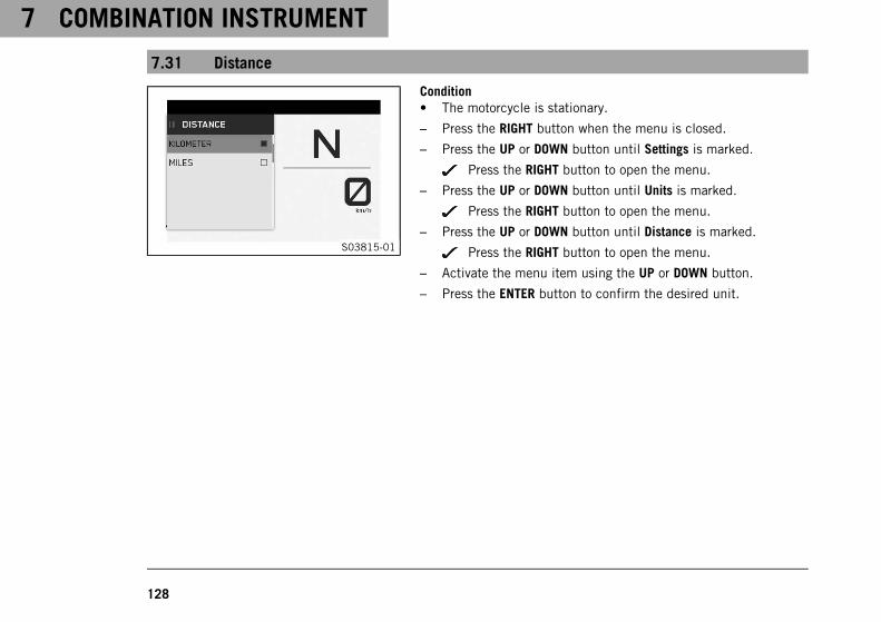
7 COMBINATION INSTRUMENT
128
7.31 Distance
S03815-01
Condition• The motorcycle is stationary.
– Press the RIGHT button when the menu is closed.
– Press the UP or DOWN button until Settings is marked.
Press the RIGHT button to open the menu.
– Press the UP or DOWN button until Units is marked.
Press the RIGHT button to open the menu.
– Press the UP or DOWN button until Distance is marked.
Press the RIGHT button to open the menu.
– Activate the menu item using the UP or DOWN button.
– Press the ENTER button to confirm the desired unit.

COMBINATION INSTRUMENT 7
129
7.32 Temperature
S03816-01
Condition• The motorcycle is stationary.
– Press the RIGHT button when the menu is closed.
– Press the UP or DOWN button until Settings is marked.
Press the RIGHT button to open the menu.
– Press the UP or DOWN button until Units is marked.
Press the RIGHT button to open the menu.
– Press the UP or DOWN button until Temperature is marked.
Press the RIGHT button to open the menu.
– Activate the menu item using the UP or DOWN button.
– Press the ENTER button to confirm the desired unit.

7 COMBINATION INSTRUMENT
130
7.33 Pressure
S03817-01
Condition• The motorcycle is stationary.
– Press the RIGHT button when the menu is closed.
– Press the UP or DOWN button until Settings is marked.
Press the RIGHT button to open the menu.
– Press the UP or DOWN button until Units is marked.
Press the RIGHT button to open the menu.
– Press UP or DOWNbutton until Pressure is marked.
Press the RIGHT button to open the menu.
– Activate the menu item using the UP or DOWN button.
– Press the ENTER button to confirm the desired unit.

COMBINATION INSTRUMENT 7
131
7.34 Consumption
S03818-01
Condition• The motorcycle is stationary.
– Press the RIGHT button when the menu is closed.
– Press the UP or DOWN button until Settings is marked.
Press the RIGHT button to open the menu.
– Press the UP or DOWN button until Units is marked.
Press the RIGHT button to open the menu.
– Press UP or DOWNbutton until Consumption is marked.
Press the RIGHT button to open the menu.
– Activate the menu item using the UP or DOWN button.
– Press the ENTER button to confirm the desired unit.

7 COMBINATION INSTRUMENT
132
7.35 Language
S03819-01
Condition• The motorcycle is stationary.
– Press the RIGHT button when the menu is closed.
– Press the UP or DOWN button until Settings is marked.
Press the RIGHT button to open the menu.
– Press the UP or DOWN button until Units is marked.
Press the RIGHT button to open the menu.
– Press the UP or DOWN button until Language is marked.
Press the RIGHT button to open the menu.
– Activate the menu item using the UP or DOWN button.
– Press the ENTER button to confirm the desired language.
The menu languages are US English, UK English, German, Italian,French, and Spanish.

COMBINATION INSTRUMENT 7
133
7.36 Heated Grips (optional)
S03828-01
Condition• The motorcycle is stationary.
– Press the RIGHT button when the menu is closed.
– Press the UP or DOWN button until Settings is marked.
Press the RIGHT button to open the menu.
– Press the UP or DOWN button until Heated Grips is marked.
Press the RIGHT button to open the menu.
– Press the UP or DOWN button until NOT AVAILABLE or AVAILABLEis marked.
– Press the ENTER button to confirm the selection.
InfoThe heated grip is activated or deactivated in theSettings menu. The heated grip is controlled in theMotorcycle menu, in submenu Heated Grips or inthe HEATING widget.

7 COMBINATION INSTRUMENT
134
7.37 Heated Seat (optional)
S03829-01
Condition• The motorcycle is stationary.
– Press the RIGHT button when the menu is closed.
– Press the UP or DOWN button until Settings is marked.
Press the RIGHT button to open the menu.
– Press the UP or DOWN button until Heated Seat is marked.
Press the RIGHT button to open the menu.
– Press the UP or DOWN button until Heated SeatNOT AVAILABLEor AVAILABLE is marked.
– Press the ENTER button to confirm the selection.
InfoThe seat heating is activated or deactivated in theSettings menu. The seat heating is controlled in theMotorcycle menu, in Heated Seat submenu or in thewidget HEATING.

COMBINATION INSTRUMENT 7
135
7.38 Small widget
S03787-01
– Press the UP button once when the menu is closed.
– Use the LEFTor RIGHT button to change between the informa-tion displays.
InfoIn the small widget you can switch between the individ-ual widgets.All widgets dependent on optional menus and func-tions are only available if the corresponding option isinstalled in the vehicle.
7.39 Large widget
S03788-01
– Press the UP button twice when the menu is closed.
The widget is large and displays all the information of therespective information display.
InfoAll widgets dependent on optional menus and func-tions are only available if the corresponding option isinstalled in the vehicle.

7 COMBINATION INSTRUMENT
136
7.40 KTM MY RIDE widget
S03834-10
– Press the UP button once when the menu is closed.
– Use the LEFTor RIGHT button to switch between the informationdisplays until the KTM MY RIDE widget is displayed.
– Press the ENTER button to open the large widget.
The KTM MY RIDE widget displays various status informationon the cellphone battery status, cellphone reception and theBluetooth® connection to the headset.
InfoWhen the symbols are filled in, there is a connectionbetween the combination instrument and the terminaldevice.When the symbols are not filled in, there is no connec-tion between the combination instrument and the ter-minal device.

COMBINATION INSTRUMENT 7
137
7.41 NAVIGATION widget
S03836-10
– Press the UP button once when the menu is closed.
– Use the LEFTor RIGHT button to switch between the informationdisplays until the NAVIGATION widget is displayed.
– Press the ENTER button to open the large widget.
InfoThe NAVIGATION widget is only available if the naviga-tion app is active and the TRACKmode is deactivated.The large NAVIGATION widget shows the direction arrow,the distance to the next waypoint, the road name, thearrival time and the distance to the destination.The volume of the navigation can be controlled withthe UP or DOWN button.

7 COMBINATION INSTRUMENT
138
7.42 FAVORITES widget
S03837-10
– Press the UP button once when the menu is closed.
– Use the LEFTor RIGHT button to change between the informa-tion displays until the FAVORITES widget is displayed.
– Press the ENTER button to open the large widget.
InfoIn the large FAVORITES widget, up to four areas withdifferent information types can be configured.
– Use the LEFTor RIGHT button to change between the individualareas until the desired area is highlighted.
– Press the UP or DOWN button to select the desired informationtype.
InfoThe selection is accepted after a few seconds.An area can be added using the selectionitem Item Add.An area can be removed using the selectionitem Item Add.Up to four areas can be selected and configured.The areas one to four are also the information displaysin the small FAVORITES widget.

COMBINATION INSTRUMENT 7
139
7.43 Widget INFO
S03838-10
– Press the UP button once when the menu is closed.
– Use the LEFTor RIGHT button to change between the informa-tion displays until the INFO widget is displayed.
– Press the ENTER button to open the large widget.
InfoThe small INFO widget displays the fuel level indicator,the coolant temperature indicator and the remainingrange.The large INFO widget also displays the total mileage,the ambient air temperature and the oil temperature.

7 COMBINATION INSTRUMENT
140
7.44 HEATING widget
S03839-10
– Press the UP button once when the menu is closed.
– Use the LEFTor RIGHT button to switch between the informationdisplays until the widget HEATING is displayed.
– Press the ENTER button to open the large widget.
– Press the LEFT or RIGHT button to select the heating level orthe heated grip.
– Press the UP or DOWN button to select the desired heatingintensity.
InfoThe HEATING widget is only available if it has been acti-vated in the menu SETTINGS.A selection can be made between heating intensitiesOFF, MAX, MED or MIN.The heating intensity is displayed in bars in the largewidget. The more bars displayed, the higher the heatingintensity.

COMBINATION INSTRUMENT 7
141
7.45 MUSIC widget
S03840-10
– Press the UP button once when the menu is closed.
– Use the LEFTor RIGHT button to change between the informa-tion displays until the MUSIC widget is displayed.
WarningDanger of accidents Headphone volume which is toohigh distracts attention from traffic activity.
– Always select headphone volume which is lowenough for you to still clearly hear acoustic signals.
– Press the ENTER button to open the large widget.
– Press the UP button to increase the volume.
– Press the DOWN button to reduce the volume.
– Press the RIGHT button briefly to change to the next audiotrack.
– Depending on the cellphone model, press the LEFT buttonbriefly or twice to change to the previous audio track or to playthe current audio track from the start.
– Press the ENTER button to change between playback andpause.
7 COMBINATION INSTRUMENT
142
TipThe MUSIC widget is only available if a cellphone and aheadset are connected via Bluetooth® with the motorcy-cle.With some cellphones, the cellphone's audio playerneeds to be started before playback is possible. Foreasier operation, the MUSIC function can be added tothe C1 or C2 switch.

ERGONOMICS 8
143
8.1 Handlebar position
S01727-11
On the upper triple clamp there are two holes at a distance ofAapart.
Hole distanceA 15 mm (0.59 in)
The handlebar can be mounted in two different positions. In thisway, the handlebar can be mounted in the most comfortable posi-tion for the rider.
InfoKTM recommends the front handlebar position when usingthe vehicle on a race track.
8.2 Adjusting the handlebar position
WarningDanger of accidents A repaired handlebar poses a safety risk.
If the handlebar is bent or straightened, the material becomes fatigued. The handlebar may break as aresult.
– Change the handlebar if the handlebar is damaged or bent.

8 ERGONOMICS
144
S01727-10
– Remove screws1. Take off the handlebar clamps2. Posi-tion the handlebar so that screws3 are accessible.
InfoCover the components to protect them against damage.Do not kink the cables and lines.
– Remove screws3. Take off handlebar supports4.
– Move the handlebar supports into the desired positionAorB. Mount and tighten screws3.
Guideline
Mount the left and right handlebar supports in the sameposition.
Screw, handle-bar support
M10 40 Nm (29.5 lbf ft)Loctite®243™
– Position the handlebar.
InfoMake sure the cables and wiring are positioned cor-rectly.
– Position the handlebar clamp. Mount screws1 and tightenevenly.
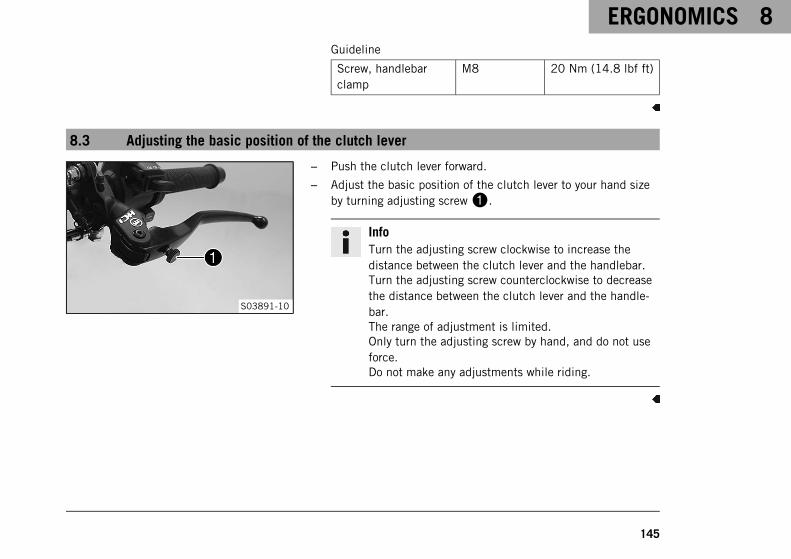
ERGONOMICS 8
145
Guideline
Screw, handlebarclamp
M8 20 Nm (14.8 lbf ft)
8.3 Adjusting the basic position of the clutch lever
S03891-10
– Push the clutch lever forward.
– Adjust the basic position of the clutch lever to your hand sizeby turning adjusting screw1.
InfoTurn the adjusting screw clockwise to increase thedistance between the clutch lever and the handlebar.Turn the adjusting screw counterclockwise to decreasethe distance between the clutch lever and the handle-bar.The range of adjustment is limited.Only turn the adjusting screw by hand, and do not useforce.Do not make any adjustments while riding.

8 ERGONOMICS
146
8.4 Adjusting the basic position of the hand brake lever
S03892-10
– Push the hand brake lever forward.
– Adjust the basic position of the hand brake lever to your handsize by turning adjusting screw1.
InfoTurn the adjusting screw clockwise to increase thedistance between the hand brake lever and the han-dlebar.Turn the adjusting screw counterclockwise to decreasethe distance between the hand brake lever and the han-dlebar.The range of adjustment is limited.Only turn the adjusting screw by hand, and do not useforce.Do not make any adjustments while riding.

ERGONOMICS 8
147
8.5 Setting the step plate of the foot brake lever
S03894-10
– Loosen screw1.
– Turn the step plate of the foot brake lever to the desired posi-tion.
Guideline
Standard Step plate positioned to thefront
InfoThe step plate of the foot brake lever can be freelyrotated through 360 °.The basic position of the foot brake lever is set at thefactory and does not need to be changed.
– Tighten screw1.
Guideline
Screw, step plate forfoot brake lever
M6 10 Nm (7.4 lbf ft)

8 ERGONOMICS
148
8.6 Checking the basic position of the shift lever
InfoWhen driving, the shift lever must not touch the rider's boot when in the basic position.If the shift lever is permanently touching the boot, the transmission will be subject to excessive load; thiscan cause a malfunction of the quickshifter.
400692-10
– Sit on the vehicle in the riding position and determinedistanceA between the upper edge of your boot and the shiftlever.
Distance between shift leverand upper edge of boot
10 … 20 mm (0.39 …0.79 in)
» If the distance does not meet specifications:
– Set the shift lever stub. ( p. 149)

ERGONOMICS 8
149
8.7 Setting the shift lever stub
S03896-10
– Loosen screw1.
– Turn the shift lever stub to the desired position.
Guideline
Standard Step plate positioned to thefront
InfoThe shift lever stub can be freely rotated through360 °.The shift lever stud is set at the factory and does notneed to be changed.
– Tighten the screw.
Guideline
Screw, shift leverstub
M6 10 Nm (7.4 lbf ft)

8 ERGONOMICS
150
8.8 Adjusting the footrests
InfoThe adjustable footrest support allows a more comfortable lower footrest position (normal switchingscheme) or a sporty upper footrest position (reverse switching scheme).The footrest support position and switching scheme can only be changed together.
S04086-10
– Remove screws1 on the right footrest support.
InfoPay attention to the nut when removing the lowerfootrest support bolt.
– Loosen screw2.

ERGONOMICS 8
151
S04087-10
– Position the footrest bracket.
– Mount and tighten screws1.
Guideline
Screw, frontrider footrestbracket
M8 25 Nm (18.4 lbf ft)Loctite®243™
– Tighten screw2.
Guideline
Remaining screws,chassis
M8 25 Nm (18.4 lbf ft)
S04088-10
– Remove screw3 of the shift linkage.
– Remove screws4 on the left footrest support and take offthe footrest support.
InfoPay attention to the nut when removing the lowerfootrest support bolt.

8 ERGONOMICS
152
S04089-10
– Separate the shift linkage from the shift lever and mount inposition "R".
Guideline
Screw, shift rod M6 5 Nm (3.7 lbf ft)Loctite®243™
InfoThe shift linkage is set at the factory. It is not neces-sary to adjust the shift linkage.When the footrest support is returned to the standardposition, the shift linkage on the shift lever must bemounted in position "S".
S04090-10
– Position the footrest bracket.
– Mount and tighten screws4.
Guideline
Screw, frontrider footrestbracket
M8 25 Nm (18.4 lbf ft)Loctite®243™

ERGONOMICS 8
153
S04091-10
– Position the shift linkage at one of the upper positions of theshift shaft.
Guideline
Outer position Shift power low, long shiftpath
Inner position Shift power high, short shiftpath
InfoWhen the footrest support is returned to the standardposition, one of the lower positions on the shift shaftmust be used.
– Mount and tighten screw3.
Guideline
Screw, shift rod M6 5 Nm (3.7 lbf ft)Loctite®243™
InfoThe switching scheme is now reversed.

8 ERGONOMICS
154
8.9 Adjusting the tilt of the combination instrument
InfoThe tilt of the combination instrument can be continuously adjusted using clamping on the handlebar.
S03897-10
– Remove screws1 and take off the cover.
S03898-10
– Unplug connector2.

ERGONOMICS 8
155
S03899-10
– Loosen screw3.
– Adjust tilt of the combination instrument.
Guideline
The combination instrument must also not touch any othercomponents following completion of the work.
– Tighten screw3.
Guideline
Screw, combinationinstrument clamping
M6 2 Nm (1.5 lbf ft)
S03898-10
– Plug in connector2.

8 ERGONOMICS
156
S03897-10
– Position the cover, mount and tighten screws1.

PREPARING FOR USE 9
157
9.1 Advice on preparing for first use
DangerDanger of accidents A rider who is not fit to ride poses a danger to him or herself and others.
– Do not operate the vehicle if you are not fit to ride due to alcohol, drugs or medication.
– Do not operate the vehicle if you are physically or mentally impaired.
WarningRisk of injury Missing or poor protective clothing presents an increased safety risk.
– Wear appropriate protective clothing such as helmet, boots, gloves as well as trousers and a jacketwith protectors on all rides.
– Always wear protective clothing that is in good condition and meets the legal regulations.
WarningDanger of crashing Different tire tread patterns on the front and rear wheel impair the handling charac-teristic.
Different tire tread patterns can make the vehicle significantly more difficult to control.
– Make sure that only tires with a similar tire tread pattern are fitted to the front and rear wheel.
WarningDanger of accidents Non-approved or non-recommended tires and wheels impact the handling character-istic.
– Only use tires/wheels approved by KTM with the corresponding speed index.

9 PREPARING FOR USE
158
WarningDanger of accidents New tires have reduced road grip.
The contact surface on new tires is not yet roughened.
– Run in new tires with moderate riding at alternating angles.
Running-in phase 200 km (124 mi)
WarningDanger of accidents The brake system fails in the event of overheating.
If the foot brake lever is not released, the brake linings drag continuously.
– Take your foot off the foot brake lever if you do not want to brake.
InfoWhen using your vehicle, remember that others may feel disturbed by excessive noise.
– Make sure that the pre-sales inspection work has been carried out by an authorized KTM workshop.
You will receive a delivery certificate when the vehicle is handed over.
– Before riding for the first time, read the entire Owner's Manual carefully.
– Get to know the controls.
– Adjust the motorcycle to your requirements, as described in the "Ergonomics" chapter.
– Get used to the handling characteristic of the motorcycle in a suitable area before making a longer trip. Tryalso to ride as slowly as possible to get a better feel for the motorcycle.
– Hold the handlebar firmly with both hands and keep your feet on the footrests when riding.
PREPARING FOR USE 9
159
– Run the engine in.
9.2 Running in the engine
– During the running-in phase, do not exceed the specified engine speed.
Guideline
Maximum engine speed
During first: 1,000 km (620 mi) 6,500 rpm
After first: 1,000 km (620 mi) 10,250 rpm
– Avoid fully opening the throttle!
9.3 Loading the vehicle
WarningDanger of accidents Total weight and axle loads influence the handling characteristic.
The total weight consists of: motorcycle ready for operation and with a full tank, driver and passengerwith protective clothing and helmet, and luggage.
– Do not exceed the maximum permissible overall weight or the axle loads.

9 PREPARING FOR USE
160
WarningDanger of accidents Improper mounting of cases or the tank rucksack impairs the handling characteris-tic.
– Mount and secure cases and tank rucksack according to the manufacturer's instructions.
WarningDanger of accidents Carrying luggage alters handling characteristics at high speed.
– Adapt your speed to your payload.
– Ride more slowly if your motorcycle is loaded with cases or other luggage.
Maximum speed with luggage 130 km/h (80.8 mph)
WarningDanger of accidents Overloading will destroy the baggage system.
– Observe the manufacturer's instructions on the maximum payload if you have panniers mounted toyour motorcycle.
WarningDanger of accidents Luggage which has slipped impairs visibility.
If the tail light is covered, you are less visible to traffic behind you, especially when it is dark.
– Check that your luggage is fixed properly at regular intervals.

PREPARING FOR USE 9
161
WarningDanger of accidents A high payload alters the handling characteristic and increases the stoppingdistance.
– Adapt your speed to your payload.
WarningDanger of accidents Pieces of luggage which have slipped impair the handling characteristic.
– Check that your luggage is fixed properly at regular intervals.
WarningFire hazard The hot exhaust system may burn luggage.
– Fasten your luggage in such a way that it cannot be burned or singed by the hot exhaust system.
– If luggage is carried, ensure it is fixed firmly as close as possible to the center of the vehicle and ensure evenweight distribution between the front and rear wheels.
– Do not exceed the maximum permissible weight and maximum permissible axle loads.
Guideline
Maximum permissible overall weight 425 kg (937 lb.)
Maximum permissible front axle load 165 kg (364 lb.)
Maximum permissible rear axle load 260 kg (573 lb.)

10 RIDING INSTRUCTIONS
162
10.1 Checks and maintenance measures when preparing for use
InfoBefore every trip, check the condition of the vehicle and ensure that it is roadworthy.The vehicle must be in perfect technical condition when it is being operated.
H02217-01
– Check the engine oil level. ( p. 296)
– Check the front brake fluid level. ( p. 239)
– Check the rear brake fluid level. ( p. 244)
– Check the front brake linings. ( p. 243)
– Check the brake linings of the rear brake. ( p. 248)
– Check that the brake system is functioning properly.
– Check the coolant level in the compensating tank. ( p. 287)
– Check the chain for dirt. ( p. 222)
– Check the chain tension. ( p. 224)
– Check tire condition. ( p. 257)
– Check tire pressure. ( p. 260)
– Check the settings of all controls and ensure that they can beoperated smoothly.
– Check that the electrical system is functioning properly.
– Check that luggage is properly secured.
– Check the setting of the rear mirror.
– Check the fuel level.

RIDING INSTRUCTIONS 10
163
10.2 Starting the vehicle
DangerDanger of poisoning Exhaust gases are toxic and inhaling them may result in unconsciousness and death.
– Always make sure there is sufficient ventilation when running the engine.
– Use effective exhaust extraction when starting or running the engine in an enclosed space.
CautionDanger of accidents Electronic components and safety devices will be damaged if the 12-V battery is dis-charged or missing.
If the 12-V battery is discharged or defective, malfunctions in the vehicle electronics can occur, espe-cially when starting.
– Never operate the vehicle with a discharged 12-V battery or without a 12-V battery.
NoteEngine damage High revving speed with a cold engine negatively impacts the lifespan of the engine.
– Always run the engine warm at a low speed.

10 RIDING INSTRUCTIONS
164
S03900-01
– Take the motorcycle off the side stand and sit on the motorcy-cle.
– Bring the RACE-ON key within the range of the steering lock.
– Ensure that the RACE-ON key stays in range while riding.
Guideline
Maximum range of theRACE-ON key around thesteering lock
1.5 m (4.9 ft)
InfoThe range may be reduced by decreases in battery volt-age of the RACE-ON key and by interfering radio waves.If the battery voltage of the RACE-ON key is too low,one of the ignition keys must be placed in the area ofthe steering lock ( p. 51) and must be safely storedagain after starting.
– Make sure that the start button/emergency OFF switch is in themiddle position .
– Switch on ignition; to do this, briefly press the RACE-ON but-ton (maximum of 1 second).
The steering is unlocked.
The function check of the combination instrument is run.
The ABS warning lamp goes out when starting off.

RIDING INSTRUCTIONS 10
165
InfoIf the handlebar does not unlock, move the handlebarslightly.
– Shift the transmission into neutral.
The N neutral position is displayed.
S03901-01
– Press the start button/emergency OFF switch into the lowerposition .
InfoOnly press the start button/emergency OFF switch intothe lower position when the combination instrumentfunction check has been completed.When starting, DO NOT open the throttle.Press the start button/emergency OFF switch into thelower position for a maximum of five seconds. Waitfor a least five seconds before trying again.This motorcycle is equipped with a safety starting sys-tem. You can only start the engine if the transmissionis in neutral or if the clutch lever is pulled when a gearis engaged. If the side stand is folded out and you shiftinto gear, the engine stops.

10 RIDING INSTRUCTIONS
166
10.3 Launch Control (optional)
H02000-01
Launch Control is an optional vehicle electronics function.Launch control adjusts the engine speed in order to achieve thebest possible acceleration.Launch control can be used for starting off for a maximum of threetimes in succession. Launch control is temporarily deactivatedafter the third starting off in order to protect the engine, transmis-sion and cooling system from overloading.Launch control is also deactivated if all conditions for activationare no longer met.Launch control is enabled again in the following cases: the engineruns for at least three minutes, the engine is switched off for 20minutes or a distance of 1.5 km (0.93 mi) has been covered.
10.4 Starting off
– Pull the clutch lever, shift into first gear, release the clutch lever slowly and at the same time open the throt-tle gently.

RIDING INSTRUCTIONS 10
167
10.5 Starting off with launch control (optional)
WarningDanger of accidents Launch control enables very powerful acceleration which may ask too much of anovice rider.
– Only use the launch control if you have the appropriate experience.
– Do not use launch control on public roads.
H02000-01
ConditionThe drive mode TRACK (optional) is activated.First gear is engaged.The TC indicator lamp does not light up.Coolant temperature: > 60 °C (> 140 °F)Total riding distance covered: > 1,000 km (> 620 mi)
– Activate launch control in the combination instrument.
The number of available starts is indicated on the startscreen.
– Apply full throttle with the clutch lever pulled.
The engine speed is adjusted.
6,500 rpm
The TC indicator lamp flashes quickly.
– Release clutch lever quickly but in a controlled manner.

10 RIDING INSTRUCTIONS
168
10.6 Quickshifter+ (optional)
H01989-10
If the Quickshifter+ (optional) is activated, you can shift up anddown without actuating the clutch.Because there is no need to close the throttle grip, uninterruptedgear shifts are possible.The quickshifter+ uses the shifter shaft position to check whetheror not a shift should be initiated, and sends a corresponding signalto the engine control.If the quickshifter+ is disabled in the combination instrument, theclutch needs to be actuated in the normal way for each shift.

RIDING INSTRUCTIONS 10
169
10.7 Shifting, riding
WarningDanger of accidents Abrupt load alterations can cause the vehicle to get out of control.
– Avoid abrupt load alterations and sudden braking actions.
– Adapt your speed to the road conditions.
WarningDanger of accidents If you change down at high engine speed, the rear wheel blocks and the engineraces.
– Do not change into a low gear at high engine speed.
WarningDanger of accidents Adjustments to the vehicle distract attention from traffic activity.
– Make all adjustments when the vehicle is at a standstill.
WarningRisk of injury The passenger may fall from the motorcycle if they conduct themselves incorrectly.
– Ensure that the passenger sits correctly on the passenger seat, places his or her feet on the passengerfoot pegs and holds on to the rider or the grab handles.
– Note the regulations governing the minimum age of passengers in your country.

10 RIDING INSTRUCTIONS
170
WarningDanger of accidents A risky riding style constitutes a major risk.
– Comply with traffic regulations and ride defensively and with foresight to detect sources of danger asearly as possible.
WarningDanger of accidents Cold tires have reduced road grip.
– Ride the first miles carefully on every journey at moderate speed until the tires reach operating tem-perature.
WarningDanger of accidents New tires have reduced road grip.
The contact surface on new tires is not yet roughened.
– Run in new tires with moderate riding at alternating angles.
Running-in phase 200 km (124 mi)
WarningDanger of accidents Total weight and axle loads influence the handling characteristic.
The total weight consists of: motorcycle ready for operation and with a full tank, driver and passengerwith protective clothing and helmet, and luggage.
– Do not exceed the maximum permissible overall weight or the axle loads.

RIDING INSTRUCTIONS 10
171
WarningDanger of accidents Pieces of luggage which have slipped impair the handling characteristic.
– Check that your luggage is fixed properly at regular intervals.
WarningDanger of accidents A fall can damage the vehicle more seriously than it may first appear.
– Check the vehicle after a fall as you do when preparing for use.
NoteEngine damage Unfiltered intake air has a negative effect on the service life of the engine.
Dust and dirt will enter the engine without an air filter.
– Only operate the vehicle if it is equipped with an air filter.
NoteEngine failure Overheating damages the engine.
– If the coolant temperature warning is displayed, stop immediately and take care not to endanger yourself orother traffic participants in the process.
– Allow the engine and cooling system to cool down.
– Check and, if necessary, correct the coolant level on the cooling system while it is in a cooled state.

10 RIDING INSTRUCTIONS
172
NoteTransmission damage Incorrect use of the quickshifter+ will damage the transmission.
The quickshifter+ can only be used if the function is enabled in the combination instrument.The quickshifter+ is not active if you pull the clutch lever.
– Only use the quickshifter+ in the permitted speed range shown.
InfoIf you hear unusual noises while riding, stop immediately, switch off the engine, and contact an autho-rized KTM workshop.All specifications regarding the switching direction refer to the standard switching scheme.
402299-11
– Shift into a higher gear when conditions allow (incline, roadsituation, etc.).
– Release the throttle while simultaneously pulling the clutchlever, shift into the next gear, release the clutch lever, andopen the throttle.
InfoThe gear positions can be seen in the figure. The idleposition is between the first and second gears. Firstgear is used for starting off or for steep inclines.
– After reaching maximum speed by fully opening the throttlegrip, turn the throttle back so it is ¾ open. This will barely

RIDING INSTRUCTIONS 10
173
reduce the speed, but fuel consumption will be considerablylower.
– Accelerate only up to a speed suitable for the road surface andweather conditions. Particularly in bends, do not shift, andaccelerate very carefully.
– Brake if necessary and close the throttle at the same time inorder to shift down.
– Pull clutch lever and shift into a lower gear, release the clutchlever slowly, and open the throttle or shift again.
– If the engine stalls (e.g., at a crossroads), just pull clutch leverand press the start button/emergency OFF switch into thelower position . The transmission must not be shifted intoneutral.
– Switch off the engine if you are likely to be running at idlespeed or stationary for a long time.
– If the oil pressure warning lamp lights up during a trip, stopimmediately and switch off the engine. Contact an authorizedKTM workshop.
– If the malfunction indicator lamp lights up during a trip,please contact an authorized KTM workshop as soon as possi-ble.
– If the general warning lamp lights up during a trip, the dis-play shows a message for 10 seconds.

10 RIDING INSTRUCTIONS
174
InfoVery important messages are stored in the Warningmenu.
– If the ice warning appears in the combination instrument, theroads may be icy. Adjust your speed to the road conditions.
H01997-10
ConditionThe quickshifter + (optional) is enabled.
– If the quickshifter + is enabled in the combination instru-ment, one can shift up in the engine speed range shownwithout pulling the clutch lever.
InfoThe minimum engine speed before shifting up inrevolutions per minute is shown in the figure.Pull the shift lever to the stop quickly withoutchanging the throttle twist grip position.

RIDING INSTRUCTIONS 10
175
H01997-11
– If the quickshifter+ is enabled in the combination instru-ment, one can shift down in the engine speed range shownwithout pulling the clutch lever.
InfoThe maximum engine speed before shifting down inrevolutions per minute is shown in the figure.Depress the shift lever to the stop quickly withoutchanging the throttle twist grip position.
10.8 MSR (optional)
402423-01
The MSR is an optional auxiliary function of the engine control.If the engine braking effect is too great, the MSR prevents the rearwheel from locking or sliding away on a sloping position.To avoid slip of the rear wheel, the MSR only opens the throttlevalve as far as absolutely necessary.The MSR is applied on surfaces, where the friction coefficient is tolow to open the slipper clutch.To further increase ride safety, the MSR is slope dependent.
InfoIf ABS is disabled, the cornering MTC is disabled orABS Mode Supermoto is enabled, the MSR is not active.

10 RIDING INSTRUCTIONS
176
10.9 Applying the brakes
WarningDanger of accidents Moisture and dirt impair the brake system.
– Brake carefully several times to dry out and remove dirt from the brake linings and the brake discs.
WarningDanger of accidents A spongy pressure point on the front or rear brake reduces braking efficiency.
– Check the brake system and do not continue riding until the problem is eliminated. (Your authorizedKTM workshop will be glad to help.)
WarningDanger of accidents The brake system fails in the event of overheating.
If the foot brake lever is not released, the brake linings drag continuously.
– Take your foot off the foot brake lever if you do not want to brake.
WarningDanger of accidents Higher total weight increases the stopping distance.
– Take the longer stopping distance into account when carrying a passenger or luggage with you.
WarningDanger of accidents Salt on the roads impairs the brake system.
– Brake carefully several times to remove salt from the brake linings and the brake discs.

RIDING INSTRUCTIONS 10
177
WarningDanger of accidents ABS may increase the stopping distance in certain situations.
– Adjust application of the brakes to the respective riding situation and riding surface conditions.
WarningDanger of accidents Excessively forceful application of the brakes blocks the wheels.
The ABS effectiveness is only ensured if it is switched on.
– Leave the ABS switched on in order to benefit from the protective effect.
WarningDanger of accidents Driving aids can reduce the probability of a fall only within physical limits.
It is not always possible to compensate for extreme riding situations, for example with luggage loadedwith a high center of gravity, varying road surfaces, steep descents or full braking without disengagingthe gear.
– Adapt your riding style to the road conditions and your driving ability.
– When braking, release the throttle and apply the front and rear brakes at the same time.
InfoWhen the ABS is enabled, you can achieve maximum braking power even on low grip surfaces such assandy, wet, or slippery terrain without locking of the wheels.

10 RIDING INSTRUCTIONS
178
WarningDanger of accidents The rear wheel can lock due to the engine braking effect.
– Pull in the clutch, if you perform emergency or full braking, or if you brake on a slippery ground.
WarningDanger of accidents Banked or laterally sloping ground reduces the maximum possible delay.
– If possible finish braking before going into a bend.
– Always finish braking before you go into a bend. Change down to a lower gear appropriate to your road speed.
– Use the braking effect of the engine on long downhill stretches. Change down one or two gears, but do notover-rev the engine. In this way, you have to brake far less and the brakes do not overheat.
10.10 Stopping, parking
WarningRisk of injury People who act without authorization endanger themselves and others.
If a valid transponder is in range, the vehicle can be started.
– Do not leave the vehicle unattended if the engine is running.
– Never leave the vehicle unattended if the RACE-ON key or the black ignition key are close to the vehi-cle.
– Protect the vehicle against access by unauthorized persons.
– Lock the steering if you leave the vehicle unattended.

RIDING INSTRUCTIONS 10
179
WarningDanger of burns Some vehicle components become very hot when the vehicle is operated.
– Do not touch any parts such as the exhaust system, radiator, engine, shock absorber, or brake systembefore the vehicle parts have cooled down.
– Let the vehicle parts cool down before you perform any work on the vehicle.
NoteMaterial damage The vehicle may be damaged by incorrect procedure when parking.
Significant damage may be caused if the vehicle rolls away or falls over.The components for parking the vehicle are designed only for the weight of the vehicle.
– Park the vehicle on a firm and level surface.
– Ensure that nobody sits on the vehicle when the vehicle is parked on a stand.
NoteFire hazard Hot vehicle components pose a fire hazard and explosion risk.
– Do not park the vehicle near to materials which are highly flammable or explosive.
– Allow the vehicle to cool down before covering it.
– Apply the brakes on the motorcycle.
– Shift the transmission into neutral.
– Switch off ignition – to do this, briefly press the RACE-ON button (maximum of 1 second) with the ignitionswitched on.

10 RIDING INSTRUCTIONS
180
InfoIf the engine is switched off with the emergency OFF switch and the ignition remains switched onusing the RACE-ON button, the power supply to most electrical power consumers remains uninter-rupted. This discharges the 12-V battery. You should therefore always switch off the engine with theRACE-ON button – the emergency OFF switch is intended for emergencies only.
– Park the motorcycle on a firm surface.
– Swing side stand forward with your foot as far as it will go and lean the vehicle on it.
– Move handlebar fully to the left and press and hold the RACE-ON button (for at least 2 seconds).
The steering is locked.
InfoIf the steering lock does not engage, move the handlebar slightly.
10.11 Transporting
NoteDanger of damage The parked vehicle can roll away or fall over.
– Park the vehicle on a firm and level surface.

RIDING INSTRUCTIONS 10
181
NoteFire hazard Hot vehicle components pose a fire hazard and explosion risk.
– Do not park the vehicle near to materials which are highly flammable or explosive.
– Allow the vehicle to cool down before covering it.
401475-01
– Switch off the engine.
– Use tension belts or other suitable devices to secure themotorcycle against falling over or rolling away.

10 RIDING INSTRUCTIONS
182
10.12 Refueling
DangerFire hazard Fuel is highly flammable.
The fuel in the fuel tank expands when warm and can escape if overfilled.
– Do not fuel the vehicle in the vicinity of open flames or lit cigarettes.
– Switch off the engine for refueling.
– Make sure that no fuel is spilled; particularly not on hot parts of the vehicle.
– If any fuel is spilled, wipe it off immediately.
– Observe the specifications for refueling.
WarningDanger of poisoning Fuel is poisonous and a health hazard.
– Avoid skin, eye and clothing contact with fuel.
– Immediately consult a doctor if you swallow fuel.
– Do not inhale fuel vapors.
– In case of skin contact, rinse the affected area with plenty of water.
– Rinse the eyes thoroughly with water, and consult a doctor in case of fuel contact with the eyes.
– Change your clothing in case of fuel spills on them.
NoteMaterial damage Inadequate fuel quality causes the fuel filter to quickly become clogged.

RIDING INSTRUCTIONS 10
183
In some countries and regions, the available fuel quality and cleanliness may not be sufficient. This will result inproblems with the fuel system.
– Refuel only with clean fuel that meets the specified standards. (Your authorized KTM workshop will be glad tohelp.)
NoteEnvironmental hazard Improper handling of fuel is a danger to the environment.
– Do not allow fuel to enter the groundwater, the soil, or the sewage system.

10 RIDING INSTRUCTIONS
184
S03902-10
– Switch off the engine.
– Open fuel tank filler cap. ( p. 54)
– Fill the fuel tank with fuel up to the lower edgeA of the fillerneck.
Total fuel tankcapacity, approx.
16 l(4.2 US gal)
Super unleaded(ROZ 95)( p. 349)
– Close the fuel tank filler cap. ( p. 56)
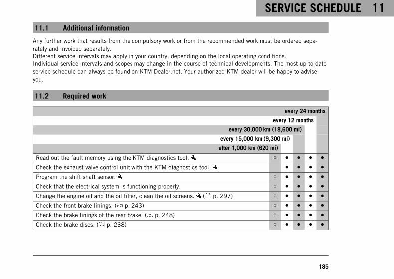
SERVICE SCHEDULE 11
185
11.1 Additional information
Any further work that results from the compulsory work or from the recommended work must be ordered sepa-rately and invoiced separately.Different service intervals may apply in your country, depending on the local operating conditions.Individual service intervals and scopes may change in the course of technical developments. The most up-to-dateservice schedule can always be found on KTM Dealer.net. Your authorized KTM dealer will be happy to adviseyou.
11.2 Required work
every 24 months
every 12 months
every 30,000 km (18,600 mi)
every 15,000 km (9,300 mi)
after 1,000 km (620 mi)
Read out the fault memory using the KTM diagnostics tool. ○ ● ● ● ●
Check the exhaust valve control unit with the KTM diagnostics tool. ● ● ● ●
Program the shift shaft sensor. ○ ● ● ● ●
Check that the electrical system is functioning properly. ○ ● ● ● ●
Change the engine oil and the oil filter, clean the oil screens. ( p. 297) ○ ● ● ● ●
Check the front brake linings. ( p. 243) ○ ● ● ● ●
Check the brake linings of the rear brake. ( p. 248) ○ ● ● ● ●
Check the brake discs. ( p. 238) ○ ● ● ● ●

11 SERVICE SCHEDULE
186
every 24 months
every 12 months
every 30,000 km (18,600 mi)
every 15,000 km (9,300 mi)
after 1,000 km (620 mi)
Check the brake lines for damage and leakage. ○ ● ● ● ●
Change the front brake fluid. ●
Change the rear brake fluid. ●
Change the hydraulic clutch fluid. ●
Check the front brake fluid level. ( p. 239) ○ ● ● ●
Check the rear brake fluid level. ( p. 244) ○ ● ● ●
Check/correct the fluid level of the hydraulic clutch. ( p. 232) ● ● ●
Check the shock absorber and fork for leaks. Perform service as needed and dependingon how the vehicle is used.
○ ● ● ● ●
Clean dust boots of the fork legs. ( p. 207) ● ●
Check the steering head bearing for play. ○ ● ● ● ●
Check tire condition. ( p. 257) ○ ● ● ● ●
Check tire pressure. ( p. 260) ○ ● ● ● ●
Check the chain, rear sprocket, engine sprocket, and chain guide. ( p. 227) ● ● ● ●
Check the chain tension. ( p. 224) ○ ● ● ● ●
Measure the wheel bearing play and grease the rear hub. ●
Check that the rear wheel nut (right side) is tightened to the specified torque. ○ ● ● ● ●

SERVICE SCHEDULE 11
187
every 24 months
every 12 months
every 30,000 km (18,600 mi)
every 15,000 km (9,300 mi)
after 1,000 km (620 mi)
Check that the exhaust clamps have the prescribed tightening torque. ○ ● ● ● ●
Check the exhaust system for leaks. ○ ● ● ● ●
Change the spark plugs (air filter removed). ●
Check the valve clearance (air filter and spark plugs removed). ●
Change the SAS membrane. ●
Check the cables for damage and routing without sharp bends (fuel tank removed). ● ● ● ●
Check the coolant level in the compensating tank. ( p. 287) ○ ● ● ● ●
Change the air filter, clean the air filter box. ● ●
Check the fuel pressure. ● ● ● ●
Check the headlight setting. ( p. 282) ○ ● ●
Check that the radiator fan is functioning properly. ○ ● ● ● ●
Final check: Check the vehicle is roadworthy and take a test ride. ○ ● ● ● ●
Read out the error memory after the test ride using the KTM diagnostics tool. ○ ● ● ● ●
Reset the service display using the KTM diagnostic tool. ○ ● ● ● ●
Make a service entry in KTM Dealer.net. ○ ● ● ● ●
○ One-time interval
● Periodic interval
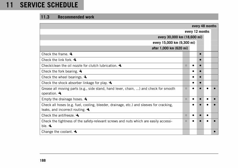
11 SERVICE SCHEDULE
188
11.3 Recommended work
every 48 months
every 12 months
every 30,000 km (18,600 mi)
every 15,000 km (9,300 mi)
after 1,000 km (620 mi)
Check the frame. ●
Check the link fork. ●
Check/clean the oil nozzle for clutch lubrication. ○ ● ●
Check the fork bearing. ● ●
Check the wheel bearings. ● ●
Check the shock absorber linkage for play. ● ●
Grease all moving parts (e.g., side stand, hand lever, chain, ...) and check for smoothoperation.
○ ● ● ● ●
Empty the drainage hoses. ○ ● ● ● ●
Check all hoses (e.g. fuel, cooling, bleeder, drainage, etc.) and sleeves for cracking,leaks, and incorrect routing.
● ● ● ●
Check the antifreeze. ○ ● ● ●
Check the tightness of the safety-relevant screws and nuts which are easily accessi-ble.
○ ● ● ● ●
Change the coolant. ●

SERVICE SCHEDULE 11
189
○ One-time interval
● Periodic interval

12 SUSPENSION SETTING
190
12.1 Fork/shock absorber
S04093-10
The fork and the shock absorber offer many options of adaptingthe suspension to the riding style and the payload.
InfoThe recommendations for the suspension setting are shownin table1. The table is located on the underside of thepassenger seat.
These adjustments are guidelines and should always be the basisfor a suspension setting. If the guidelines are not adhered to,the riding characteristics could deteriorate, particularly at highspeeds.
12.2 Adjusting the spring preload of the fork
S03908-10
– Turn adjusting screws1 all the way either clockwise or coun-terclockwise.
InfoMake the same adjustment on both fork legs.
– Make the appropriate adjustment for the fork type.

SUSPENSION SETTING 12
191
Guideline
Spring preload – preload adjuster
Comfort ‑ 3
Standard 0
Sport +3
Full payload +3
InfoTurn clockwise to increase the spring preload; turncounterclockwise to reduce the spring preload.Adjusting the spring preload has no influence on theabsorption setting of the rebound.Basically, however, you should set the rebound damp-ing higher with a higher spring preload.
12.3 Adjusting the compression damping of the fork
InfoThe hydraulic compression damping determines the fork suspension behavior.
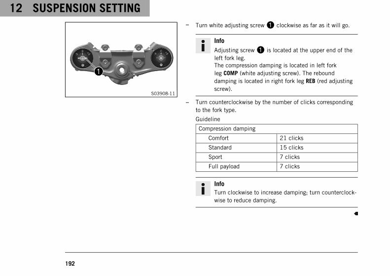
12 SUSPENSION SETTING
192
S03908-11
– Turn white adjusting screw1 clockwise as far as it will go.
InfoAdjusting screw1 is located at the upper end of theleft fork leg.The compression damping is located in left forkleg COMP (white adjusting screw). The rebounddamping is located in right fork leg REB (red adjustingscrew).
– Turn counterclockwise by the number of clicks correspondingto the fork type.
Guideline
Compression damping
Comfort 21 clicks
Standard 15 clicks
Sport 7 clicks
Full payload 7 clicks
InfoTurn clockwise to increase damping; turn counterclock-wise to reduce damping.

SUSPENSION SETTING 12
193
12.4 Adjusting the rebound damping of the fork
InfoThe hydraulic rebound damping determines the fork suspension behavior.
S03908-12
– Turn red adjusting screw1 clockwise as far as it will go.
InfoAdjusting screw1 is located at the upper end of theright fork leg.The rebound damping is located in right fork leg REB(red adjusting screw). The compression damping islocated in left fork leg COMP (white adjusting screw).
– Turn counterclockwise by the number of clicks correspondingto the fork type.
Guideline
Rebound damping
Comfort 21 clicks
Standard 15 clicks
Sport 7 clicks
Full payload 7 clicks

12 SUSPENSION SETTING
194
InfoTurn clockwise to increase damping; turn counterclock-wise to reduce damping.
12.5 Bleeding the fork legs
Preparatory work– Raise motorcycle with the work stand (inserted). ( p. 204)
S03908-13
Main work– Release bleeder screws1.
Any excess pressure escapes from the interior of the fork.
– Tighten the bleeder screws.
Finishing work– Remove the motorcycle from the work stand (inserted).
( p. 206)

SUSPENSION SETTING 12
195
12.6 Compression damping of the shock absorber
S03906-01
The compression damping of the shock absorber is divided intotwo ranges: high-speed and low-speed.High-speed and low-speed refer to the compression speed of therear wheel suspension and not to the vehicle speed.The high-speed compression adjuster, for example, has an effectwhen riding over an asphalt edge: the rear wheel suspension com-presses quickly.The low-speed compression adjuster has an effect, for example,when riding over long ground swells: the rear wheel suspensioncompresses slowly.These two ranges can be adjusted separately, although the transi-tion between high-speed and low-speed is gradual. Thus, modifi-cations in the high-speed range affect the compression damping inthe low-speed range and vice versa.

12 SUSPENSION SETTING
196
12.7 Adjusting the spring preload of the shock absorber
S03907-01
– To increase the spring preload, turn handwheel1clockwise.
– To reduce the spring preload, turn hand-wheel1counterclockwise.
Guideline
Spring preload
Standard 0
Maximum 15
Minimum −5
12.8 Adjusting the low-speed compression damping of the shock absorber
CautionRisk of injury Parts of the shock absorber will move around if the shock absorber is detached incorrectly.
The shock absorber is filled with highly compressed nitrogen.
– Please follow the description provided. (Your authorized KTM workshop will be glad to help.)
InfoThe low-speed compression adjuster takes effect during slow to normal compression of the shock absorber.

SUSPENSION SETTING 12
197
S03909-10
– Turn adjusting screw1 clockwise with a screwdriver as far asthe last perceptible click.
InfoDo not loosen fitting2!
– Turn counterclockwise by the number of clicks correspondingto the shock absorber type.
Guideline
Low-speed compression damping
Comfort 21 clicks
Standard 12 clicks
Sport 7 clicks
Full payload 7 clicks
InfoTurn clockwise to increase damping; turn counterclock-wise to reduce damping.

12 SUSPENSION SETTING
198
12.9 Adjusting the high-speed compression damping of the shock absorber
CautionRisk of injury Parts of the shock absorber will move around if the shock absorber is detached incorrectly.
The shock absorber is filled with highly compressed nitrogen.
– Please follow the description provided. (Your authorized KTM workshop will be glad to help.)
InfoThe high-speed compression adjuster takes effect during fast compression of the shock absorber.
S03906-10
– Turn adjusting screw1 all the way clockwise with a socketwrench.
InfoDo not loosen fitting2!
– Turn counterclockwise by the number of turns correspondingto the shock absorber type.

SUSPENSION SETTING 12
199
Guideline
High-speed compression damping
Comfort 1.5 turns
Standard 1.5 turns
Sport 1 turn
Full payload 1 turn
InfoTurn clockwise to increase damping; turn counterclock-wise to reduce damping.
12.10 Adjusting the rebound damping of the shock absorber
CautionRisk of injury Parts of the shock absorber will move around if the shock absorber is detached incorrectly.
The shock absorber is filled with highly compressed nitrogen.
– Please follow the description provided. (Your authorized KTM workshop will be glad to help.)

12 SUSPENSION SETTING
200
S03910-10
– Turn adjusting screw1 clockwise up to the last perceptibleclick.
– Turn counterclockwise by the number of clicks correspondingto the shock absorber type.
Guideline
Rebound damping
Comfort 21 clicks
Standard 15 clicks
Sport 10 clicks
Full payload 10 clicks
InfoTurn clockwise to increase damping; turn counterclock-wise to reduce damping.

SERVICE WORK ON THE CHASSIS 13
201
13.1 Lifting the motorcycle with the rear lifting gear
NoteDanger of damage The parked vehicle can roll away or fall over.
– Park the vehicle on a firm and level surface.
E00695-01
– Place the adapter into the rear lifting gear.
Rear wheel work stand for single-sided swing arm(61329955000)
– Position the motorcycle upright, place the lifting gear in theaxle, and raise the motorcycle.
13.2 Removing the rear of motorcycle from the lifting gear
NoteDanger of damage The parked vehicle can roll away or fall over.
– Park the vehicle on a firm and level surface.

13 SERVICE WORK ON THE CHASSIS
202
402029-10
– Secure the motorcycle against falling over.
– Remove the rear wheel stand and lean the vehicle on sidestand1.
13.3 Lifting the motorcycle with the front lifting gear
NoteDanger of damage The parked vehicle can roll away or fall over.
– Park the vehicle on a firm and level surface.
Preparatory work– Lift the motorcycle with the rear lifting gear. ( p. 201)

SERVICE WORK ON THE CHASSIS 13
203
E00696-01
Main work– Move the handlebar to the straight-ahead position. Align the
front lifting gear with the fork legs.
Front wheel work stand, small (61129965000)
InfoAlways raise the motorcycle at the rear first.
– Lift the motorcycle at the front.
13.4 Taking the motorcycle off the front lifting gear
NoteDanger of damage The parked vehicle can roll away or fall over.
– Park the vehicle on a firm and level surface.

13 SERVICE WORK ON THE CHASSIS
204
402777-01
– Secure the motorcycle against falling over.
– Remove the front lifting gear.
13.5 Raising the motorcycle with the work stand (inserted)
NoteDanger of damage The parked vehicle can roll away or fall over.
– Park the vehicle on a firm and level surface.

SERVICE WORK ON THE CHASSIS 13
205
S04100-01
– Remove the plastic caps on both sides.
– The plastic bushing of the work stand should engage in theopening of the swingarm pivot. Select the right height andwidth of the work stand.
Work stand (62529055200)
– Raise the motorcycle.
InfoCheck that the work stand is properly seated.

13 SERVICE WORK ON THE CHASSIS
206
13.6 Removing the motorcycle from the work stand (inserted)
NoteDanger of damage The parked vehicle can roll away or fall over.
– Park the vehicle on a firm and level surface.

SERVICE WORK ON THE CHASSIS 13
207
S04101-01
– Remove the motorcycle from the work stand and rest it on theside stand.
– Remove the work stand.
Work stand (62529055200)
– Insert the plastic caps on both sides.
13.7 Cleaning the dust boots of the fork legs
Preparatory work– Lift the motorcycle with the rear lifting gear. ( p. 201)
– Lift the motorcycle with the front lifting gear. ( p. 202)

13 SERVICE WORK ON THE CHASSIS
208
S03950-10
Main work– Push dust boots1 of both fork legs downward.
InfoThe dust boots remove dust and coarse dirt particlesfrom the inside fork tubes. Over time, dirt can accumu-late behind the dust boots. If this dirt is not removed,the oil seals behind can start to leak.
WarningDanger of accidents Oil or grease on the brake discsreduces the braking effect.
– Always keep the brake discs free of oil and grease.
– Clean the brake discs with brake cleaner when nec-essary.
– Clean and oil the dust boots and inner fork tubes of both forklegs.
Universal oil spray ( p. 351)
– Press dust boots back into the installation position.
– Remove excess oil.
Finishing work– Take the motorcycle off the front lifting gear. ( p. 203)

SERVICE WORK ON THE CHASSIS 13
209
– Remove the rear of the motorcycle from the lifting gear.( p. 201)
13.8 Removing the passenger seat
S03911-10
– Insert the RACE-ON key or the black ignition key into seatlock1 and turn clockwise.
– Lift passenger seat at the front and pull it out of the brackettoward the front.
– Remove the passenger seat.
– Remove the ignition key.

13 SERVICE WORK ON THE CHASSIS
210
13.9 Mounting the passenger seat
S03912-10
– Hook recesses1 of the passenger seat in guides2 andlower the front seat while pushing it back.
– Position the locking pin in the lock housing and push the pas-senger seat down at the front.
The locking pin engages with an audible click.
– Check that the passenger seat is mounted correctly.

SERVICE WORK ON THE CHASSIS 13
211
13.10 Removing the front rider's seat
Preparatory work– Remove the passenger seat. ( p. 209)
S03913-10
Main work– Unlock the front rider's seat with loop1 underneath the pas-
senger seat.
– Raise the front rider's seat at the rear and remove it.

13 SERVICE WORK ON THE CHASSIS
212
13.11 Mounting the front rider's seat
S03914-10
Main work– Hook recess1 of the front rider's seat into guide2, lower it
at the rear and push it forward.
– Position the locking pin in the lock housing and push the pas-senger seat down at the front.
The locking pin engages with an audible click.
– Check that the front rider's seat is mounted correctly.
Finishing work– Mount the passenger seat. ( p. 210)

SERVICE WORK ON THE CHASSIS 13
213
13.12 Removing left fuel tank spoiler
S04082-10
– Raise fuel tank cover1 in areaA and remove in the upwarddirection.

13 SERVICE WORK ON THE CHASSIS
214
S04083-10
– Remove screws2.
– Raise the fuel tank spoiler in areaB and remove it towardthe front.

SERVICE WORK ON THE CHASSIS 13
215
13.13 Installing the left fuel tank spoiler
S04084-10
– Position the fuel tank spoiler on holding lugsA,B andCand slide from front to rear.

13 SERVICE WORK ON THE CHASSIS
216
S04083-11
– Press right fuel tank spoiler in the rubber bushing in areaD.
– Mount screws1.
Guideline
Screw, trim M5 3.5 Nm(2.58 lbf ft)
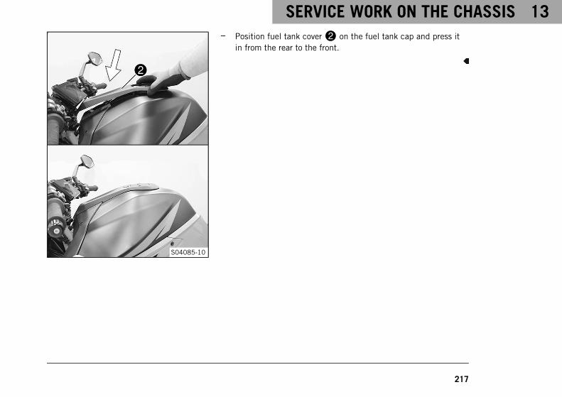
SERVICE WORK ON THE CHASSIS 13
217
S04085-10
– Position fuel tank cover2 on the fuel tank cap and press itin from the rear to the front.

13 SERVICE WORK ON THE CHASSIS
218
13.14 Removing the main silencer
WarningDanger of burns The exhaust system gets very hot when the vehicle is driven.
– Allow the exhaust system to cool down before performing any work on the vehicle.
S03915-10
– Remove screws1 and take off the cover.
– Remove screw2 and take off exhaust clamp.

SERVICE WORK ON THE CHASSIS 13
219
S03916-10
– Remove screw3 with the washer.
WarningRisk of injury Moving parts of the exhaust valve con-stitute a risk of injury.
– Do not touch the exhaust valve if the main silencerhas been removed.
– Make sure that nobody gets caught when theexhaust valve is actuated.
– Take off the main silencer.
S03917-10
– Remove seal ring4.
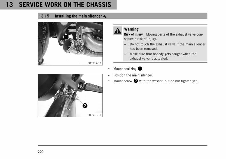
13 SERVICE WORK ON THE CHASSIS
220
13.15 Installing the main silencer
S03917-11
WarningRisk of injury Moving parts of the exhaust valve con-stitute a risk of injury.
– Do not touch the exhaust valve if the main silencerhas been removed.
– Make sure that nobody gets caught when theexhaust valve is actuated.
– Mount seal ring1.
S03916-11
– Position the main silencer.
– Mount screw2 with the washer, but do not tighten yet.

SERVICE WORK ON THE CHASSIS 13
221
S03915-11
– Position the exhaust clamp.
– Mount and tighten screw3.
Guideline
Screw, exhaustclamp on mainsilencer
M6 10 Nm (7.4 lbf ft)
– Tighten screw2.
Guideline
Remaining screws,chassis
M8 25 Nm (18.4 lbf ft)
– Position the cover.
– Tighten screws4.
Guideline
Screw, heat guard onmain silencer
M5 4 Nm (3 lbf ft)

13 SERVICE WORK ON THE CHASSIS
222
13.16 Checking the chain for dirt
400678-01
– Check the chain for coarse dirt accumulation.
» If the chain is very dirty:
– Clean the chain. ( p. 222)
13.17 Cleaning the chain
WarningDanger of accidents Lubricants on the tires reduces the road grip.
– Remove lubricants from the tires using a suitable cleaning agent.
WarningDanger of accidents Oil or grease on the brake discs reduces the braking effect.
– Always keep the brake discs free of oil and grease.
– Clean the brake discs with brake cleaner when necessary.

SERVICE WORK ON THE CHASSIS 13
223
NoteEnvironmental hazard Hazardous substances cause environmental damage.
– Dispose of oils, grease, filters, fuel, cleaning agents, brake fluid, etc., correctly and in compliance withthe applicable regulations.
InfoThe service life of the chain depends largely on its maintenance.Regular cleaning increases the service life of the chain.
Preparatory work– Lift the motorcycle with the rear lifting gear. ( p. 201)
400725-01
Main work– Rinse off loose dirt with a soft jet of water.
– Remove old grease residue with chain cleaner.
Chain cleaner ( p. 350)
– After drying, apply chain spray.
Street chain spray ( p. 351)
Finishing work– Remove the rear of the motorcycle from the lifting gear.
( p. 201)

13 SERVICE WORK ON THE CHASSIS
224
13.18 Checking the chain tension
WarningDanger of accidents Incorrect chain tension damages components and results in accidents.
If the chain is tensioned too much, the chain, engine sprocket, rear sprocket, transmission and rearwheel bearings wear more quickly. Some components may break if overloaded.If the chain is too loose, the chain may fall off the engine sprocket or the rear sprocket. As a result, therear wheel locks or the engine will be damaged.
– Check the chain tension regularly.
– Set the chain tension in accordance with the specification.
Preparatory work– Lift the motorcycle with the rear lifting gear. ( p. 201)
S03918-10
Main work– Shift the transmission into neutral.
– At the chain sliding guard in the area of markingsA andB,push the chain upward and determine the chain tension.
InfoThe lower chain section must be taut.Chain wear is not always even, so you should repeatthis measurement at different chain positions.

SERVICE WORK ON THE CHASSIS 13
225
The upper edge of the chain is located betweenmarkingsA andB.
» If the chain tension does not meet the specification:
– Adjust the chain tension. ( p. 226)
H00380-11
– Check protection caps1 for damage and tightness.
» If the protection caps are damaged or loose:
– Replace the protection caps.
Link fork protection cap (61304041100)
Finishing work– Remove the rear of the motorcycle from the lifting gear.
( p. 201)
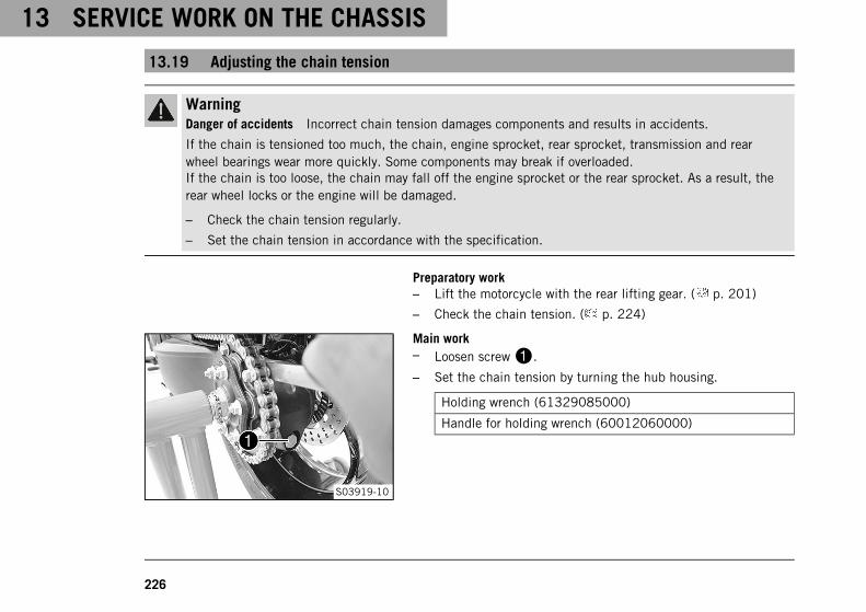
13 SERVICE WORK ON THE CHASSIS
226
13.19 Adjusting the chain tension
WarningDanger of accidents Incorrect chain tension damages components and results in accidents.
If the chain is tensioned too much, the chain, engine sprocket, rear sprocket, transmission and rearwheel bearings wear more quickly. Some components may break if overloaded.If the chain is too loose, the chain may fall off the engine sprocket or the rear sprocket. As a result, therear wheel locks or the engine will be damaged.
– Check the chain tension regularly.
– Set the chain tension in accordance with the specification.
Preparatory work– Lift the motorcycle with the rear lifting gear. ( p. 201)
– Check the chain tension. ( p. 224)
S03919-10
Main work– Loosen screw1.
– Set the chain tension by turning the hub housing.
Holding wrench (61329085000)
Handle for holding wrench (60012060000)

SERVICE WORK ON THE CHASSIS 13
227
InfoTurn clockwise to increase the chain tension; turncounterclockwise to reduce the chain tension.The tool required is in the tool set.
– Check the chain tension. ( p. 224)
The chain tension matches the specified value.
InfoChain wear is not always even, so you should repeatthis measurement at different chain positions.
– Tighten screw1.
Guideline
Screw, eccentric M16 70 Nm (51.6 lbf ft)
– Remove the rear of the motorcycle from the lifting gear.( p. 201)
13.20 Checking the chain, rear sprocket, engine sprocket, and chain guide
Preparatory work– Lift the motorcycle with the rear lifting gear. ( p. 201)

13 SERVICE WORK ON THE CHASSIS
228
100132-10
Main work– Check the chain, rear sprocket, and engine sprocket for wear.
» If the chain, rear sprocket or motor sprocket is worn:
– Change the drivetrain kit.
InfoThe engine sprocket, the rear sprocket, and thechain should always be replaced together.

SERVICE WORK ON THE CHASSIS 13
229
S03949-10
– Shift the transmission into neutral.
– Pull on the top section of the chain with the specifiedweightA.
Guideline
Weight, chain wear measure-ment
15 kg (33 lb.)
– Measure distanceB of 18 chain rollers in the upper chainsection.
InfoChain wear is not always even, so you should repeatthis measurement at different chain positions.
Maximum distanceB from18 chain rollers at thelongest chain section
272 mm (10.71 in)
» If distanceB is greater than the specified measurement:
– Change the drivetrain kit.

13 SERVICE WORK ON THE CHASSIS
230
InfoWhen a new chain is mounted, the rear sprocketand the engine sprocket should also bechanged.New chains wear out faster on an old, worn rearsprocket or engine sprocket.For safety reasons, the chain has no chain joint.
S04102-01
– Check the chain sliding guard for wear.
» If the chain sliding guard shows a lot of wear:
– Change the chain sliding guard.
– Check that the chain sliding guard is firmly seated.
» If the chain sliding guard is loose:
– Tighten screws on the chain sliding guard.
Guideline
Screw, chain slid-ing guard
M5 5 Nm (3.7 lbf ft)

SERVICE WORK ON THE CHASSIS 13
231
S04103-01
– Check the chain sliding piece for wear.
» If the lower edge of the chain is in line with or below thechain sliding piece:
– Change the chain sliding piece.
– Check that the chain sliding piece is firmly seated.
» If the chain sliding piece is loose:
– Tighten screw on the chain sliding piece.
Guideline
Remaining screws,chassis
M8 25 Nm(18.4 lbf ft)
Finishing work– Remove the rear of the motorcycle from the lifting gear.
( p. 201)

13 SERVICE WORK ON THE CHASSIS
232
13.21 Checking/correcting the fluid level of the hydraulic clutch
WarningSkin irritation Brake fluid causes skin irritation.
– Keep brake fluid out of the reach of children.
– Wear suitable protective clothing and safety glasses.
– Do not allow brake fluid to come into contact with the skin, the eyes or clothing.
– Consult a doctor immediately if brake fluid has been swallowed.
– Rinse the affected area with plenty of water in the event of contact with the skin.
– Rinse eyes thoroughly with water immediately and consult a doctor if brake fluid comes into contactwith the eyes.
– If brake fluid spills on to your clothing, change the clothing.
NoteEnvironmental hazard Hazardous substances cause environmental damage.
– Dispose of oils, grease, filters, fuel, cleaning agents, brake fluid, etc., correctly and in compliance withthe applicable regulations.

SERVICE WORK ON THE CHASSIS 13
233
InfoThe fluid level rises with increasing wear of the clutch facing discs.Never use DOT 5 brake fluid. It is silicone-based and purple in color. Oil seals and clutch lines are notdesigned for DOT 5 brake fluid.Avoid contact between brake fluid and painted parts. Brake fluid attacks paint.Only use clean brake fluid from a sealed container.

13 SERVICE WORK ON THE CHASSIS
234
S03920-10
– Move the clutch fluid reservoir mounted on the handlebar to ahorizontal position.
– Check the fluid level.
The fluid level must be between MIN and MAX markings.
» If the fluid level does not meet specifications:
– Remove screw cap1 with membrane2 and theshim.
– Correct the fluid level of the hydraulic clutch.
Brake fluid DOT 4 / DOT 5.1 ( p. 346)
– Mount and tighten screw cap1 with membrane2and the shim.
InfoClean up overflowed or spilled brake fluidimmediately with water.

BRAKE SYSTEM 14
235
14.1 Anti-lock braking system (ABS)
H01998-10
The ABS module1, which consists of a hydraulic unit, ABS con-trol unit, and return pump, is installed on the right side of thevehicle below the fuel tank. One wheel speed sensor2 is locatedin each case on the front and the rear wheel.
WarningDanger of accidents Changes to the vehicle impair thefunction of the ABS.
– Do not make any changes to the suspension travel.
– Only use spare parts on the brake system which havebeen approved and recommended by KTM.
– Only use tires/wheels approved by KTM with the corre-sponding speed index.
– Maintain the specified tire pressure.
– Ensure that service work and repairs are performedprofessionally. (Your authorized KTM workshop will beglad to help.)
The ABS is a safety system that, within physical limitations, canprevent locking and slipping of the wheels during braking.

14 BRAKE SYSTEM
236
WarningDanger of accidents Driving aids can reduce the probabil-ity of a fall only within physical limits.
It is not always possible to compensate for extreme ridingsituations, for example with luggage loaded with a highcenter of gravity, varying road surfaces, steep descents orfull braking without disengaging the gear.
– Adapt your riding style to the road conditions and yourdriving ability.
ABS has two operating modes, the Road ABS mode and ABS modeSupermoto.In the Road ABS mode, the ABS controls both wheels.In ABS mode Supermoto, the ABS only controls the frontwheel. There is no ABS control on the rear wheel. TheABS warning lamp3 flashes slowly to remind you that theSupermoto ABS mode is enabled.
InfoIn the Supermoto ABS mode, the rear wheel may lock andthere is a risk of falling.
The ABS operates with two independent brake circuits (front andrear brakes). When the ABS control unit detects a locking ten-dency in a wheel, ABS begins regulating the brake pressure. The
BRAKE SYSTEM 14
237
control function causes a slight pulsing of the hand and foot brakelevers.The ABS warning lamp3 must light up after the ignition isswitched on and go out after starting off. If it does not go out afterstarting off or if it is lit while riding, this indicates a fault in theABS. In this case, the ABS is no longer enabled and the wheelsmay lock during braking. The brake system itself stays functional;only ABS control is not available.The ABS warning lamp may also light up if the rotating speeds ofthe front and rear wheels differ greatly under extreme riding con-ditions, for example when making "wheelies" or if the rear wheelspins. This causes the ABS to switch off.To reactivate the ABS, stop the vehicle and switch off the ignition.The ABS is reactivated when the vehicle is switched on again. TheABS warning lamp goes out after starting off.
MSCThe MSC is a supplementary function for the ABS that can preventblocking and slipping of the wheels during braking when the vehi-cle is inclined (riding in curves) within the physical limitations.By means of the inclination sensor, ABS control is now dependenton the inclination and pitch angle.
InfoThe MSC is only active in Road ABS mode.

14 BRAKE SYSTEM
238
14.2 Checking the brake discs
WarningDanger of accidents Worn-out brake discs reduce the braking effect.
– Make sure that worn-out brake discs are replaced immediately. (Your authorized KTM workshop willbe glad to help.)
100135-10
– Check the front and rear brake disc thickness at multiplepoints for the dimensionA.
InfoWear will reduce the thickness of the brake disc at con-tact surface1 of the brake linings.
Brake discs - wear limit
front 4.5 mm (0.177 in)
rear 4.5 mm (0.177 in)
» If the brake disc thickness is less than the specified value:
– Change the front brake discs.
– Change the rear brake disc.
– Check the front and rear brake discs for damage, cracking, anddeformation.

BRAKE SYSTEM 14
239
» If the brake disc exhibits damage, cracking, or deforma-tion:
– Change the front brake discs.
– Change the rear brake disc.
14.3 Checking the front brake fluid level
WarningDanger of accidents An insufficient brake fluid level will cause the brake system to fail.
If the brake fluid level drops below the MIN marking, the brake system is leaking or the brake linings areworn down.
– Check the brake system and do not continue riding until the problem is eliminated. (Your authorizedKTM workshop will be glad to help.)
WarningDanger of accidents Old brake fluid reduces the braking effect.
– Make sure that brake fluid for the front and rear brake is changed in accordance with the serviceschedule. (Your authorized KTM workshop will be glad to help.)

14 BRAKE SYSTEM
240
S03921-10
– Move the brake reservoir mounted on the handlebar to a hori-zontal position.
– Check the brake fluid level in brake fluid reservoir1.
» If the brake fluid level has dropped belowMIN markingA:
– Add front brake fluid. ( p. 240)
14.4 Adding front brake fluid
WarningDanger of accidents An insufficient brake fluid level will cause the brake system to fail.
If the brake fluid level drops below the MIN marking, the brake system is leaking or the brake linings areworn down.
– Check the brake system and do not continue riding until the problem is eliminated. (Your authorizedKTM workshop will be glad to help.)

BRAKE SYSTEM 14
241
WarningSkin irritation Brake fluid causes skin irritation.
– Keep brake fluid out of the reach of children.
– Wear suitable protective clothing and safety glasses.
– Do not allow brake fluid to come into contact with the skin, the eyes or clothing.
– Consult a doctor immediately if brake fluid has been swallowed.
– Rinse the affected area with plenty of water in the event of contact with the skin.
– Rinse eyes thoroughly with water immediately and consult a doctor if brake fluid comes into contactwith the eyes.
– If brake fluid spills on to your clothing, change the clothing.
WarningDanger of accidents Old brake fluid reduces the braking effect.
– Make sure that brake fluid for the front and rear brake is changed in accordance with the serviceschedule. (Your authorized KTM workshop will be glad to help.)
NoteEnvironmental hazard Hazardous substances cause environmental damage.
– Dispose of oils, grease, filters, fuel, cleaning agents, brake fluid, etc., correctly and in compliance withthe applicable regulations.

14 BRAKE SYSTEM
242
InfoNever use DOT 5 brake fluid. It is silicone-based and purple in color. Oil seals and brake lines are notdesigned for DOT 5 brake fluid.Avoid contact between brake fluid and painted parts. Brake fluid attacks paint.Only use clean brake fluid from a sealed container.
Preparatory work– Check the front brake linings. ( p. 243)
S03922-10
Main work– Move the brake reservoir mounted on the handlebar to a hori-
zontal position.
– Remove screws1.
– Take off cover2 with membrane3.
– Add brake fluid up to MAX markingA.
Brake fluid DOT 4 / DOT 5.1 ( p. 346)
– Position cover2 with membrane3.
– Mount and tighten screws1.
InfoClean up overflowed or spilled brake fluid immediatelywith water.
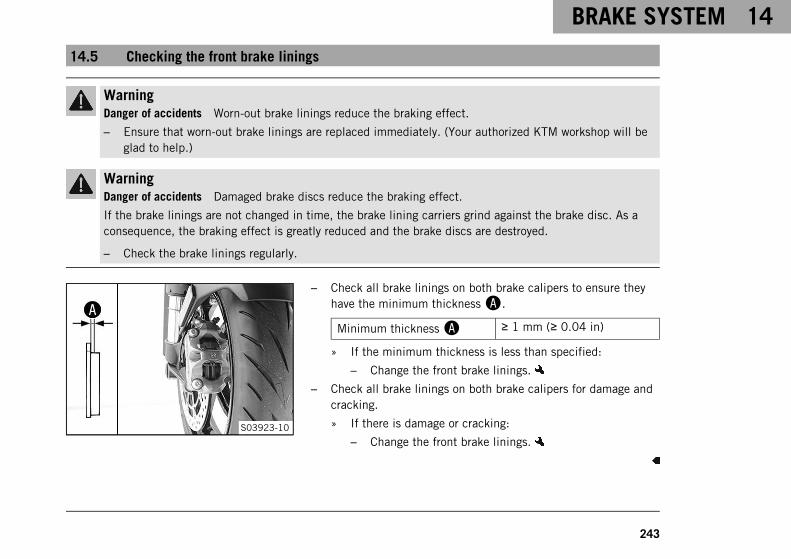
BRAKE SYSTEM 14
243
14.5 Checking the front brake linings
WarningDanger of accidents Worn-out brake linings reduce the braking effect.
– Ensure that worn-out brake linings are replaced immediately. (Your authorized KTM workshop will beglad to help.)
WarningDanger of accidents Damaged brake discs reduce the braking effect.
If the brake linings are not changed in time, the brake lining carriers grind against the brake disc. As aconsequence, the braking effect is greatly reduced and the brake discs are destroyed.
– Check the brake linings regularly.
S03923-10
– Check all brake linings on both brake calipers to ensure theyhave the minimum thicknessA.
Minimum thicknessA ≥ 1 mm (≥ 0.04 in)
» If the minimum thickness is less than specified:
– Change the front brake linings.
– Check all brake linings on both brake calipers for damage andcracking.
» If there is damage or cracking:
– Change the front brake linings.

14 BRAKE SYSTEM
244
14.6 Checking the rear brake fluid level
WarningDanger of accidents An insufficient brake fluid level will cause the brake system to fail.
If the brake fluid level drops below the MIN marking, the brake system is leaking or the brake linings areworn down.
– Check the brake system and do not continue riding until the problem is eliminated. (Your authorizedKTM workshop will be glad to help.)
WarningDanger of accidents Old brake fluid reduces the braking effect.
– Make sure that brake fluid for the front and rear brake is changed in accordance with the serviceschedule. (Your authorized KTM workshop will be glad to help.)
S03924-10
– Stand the vehicle upright.
– Check the brake fluid level in brake fluid reservoir1.
» If the fluid level reaches the MIN markingA:
– Add rear brake fluid. ( p. 245)

BRAKE SYSTEM 14
245
14.7 Adding rear brake fluid
WarningDanger of accidents An insufficient brake fluid level will cause the brake system to fail.
If the brake fluid level drops below the MIN marking, the brake system is leaking or the brake linings areworn down.
– Check the brake system and do not continue riding until the problem is eliminated. (Your authorizedKTM workshop will be glad to help.)
WarningSkin irritation Brake fluid causes skin irritation.
– Keep brake fluid out of the reach of children.
– Wear suitable protective clothing and safety glasses.
– Do not allow brake fluid to come into contact with the skin, the eyes or clothing.
– Consult a doctor immediately if brake fluid has been swallowed.
– Rinse the affected area with plenty of water in the event of contact with the skin.
– Rinse eyes thoroughly with water immediately and consult a doctor if brake fluid comes into contactwith the eyes.
– If brake fluid spills on to your clothing, change the clothing.

14 BRAKE SYSTEM
246
WarningDanger of accidents Old brake fluid reduces the braking effect.
– Make sure that brake fluid for the front and rear brake is changed in accordance with the serviceschedule. (Your authorized KTM workshop will be glad to help.)
NoteEnvironmental hazard Hazardous substances cause environmental damage.
– Dispose of oils, grease, filters, fuel, cleaning agents, brake fluid, etc., correctly and in compliance withthe applicable regulations.
InfoNever use DOT 5 brake fluid. It is silicone-based and purple in color. Oil seals and brake lines are notdesigned for DOT 5 brake fluid.Avoid contact between brake fluid and painted parts. Brake fluid attacks paint.Only use clean brake fluid from a sealed container.
Preparatory work– Check the brake linings of the rear brake. ( p. 248)

BRAKE SYSTEM 14
247
S03925-10
Main work– Position the vehicle upright.
– Remove screw1 with the screw cap lock.
InfoMake sure that the reservoir stays vertical and no brakefluid runs out.
– Remove screw cap2 with the washer and membrane3.
– Add brake fluid up to the MAX markingA.
Brake fluid DOT 4 / DOT 5.1 ( p. 346)
– Mount and tighten screw cap2 with the shim and mem-brane3.
– Position the screw cap lock and mount and tighten screw1.
Guideline
Screw, brakefluid reservoir,rear brake
M5 3.5 Nm (2.58 lbf ft)Loctite®243™
InfoUse water to immediately clean up any brake fluid thathas overflowed or spilled.

14 BRAKE SYSTEM
248
14.8 Checking the brake linings of the rear brake
WarningDanger of accidents Worn-out brake linings reduce the braking effect.
– Ensure that worn-out brake linings are replaced immediately. (Your authorized KTM workshop will beglad to help.)
WarningDanger of accidents Damaged brake discs reduce the braking effect.
If the brake linings are not changed in time, the brake lining carriers grind against the brake disc. As aconsequence, the braking effect is greatly reduced and the brake discs are destroyed.
– Check the brake linings regularly.
500320-10
– Check the brake linings for minimum thicknessA.
Minimum thicknessA ≥ 1 mm (≥ 0.04 in)
» If the minimum thickness is less than specified:
– Change the rear brake linings.
– Check the brake linings for damage and cracking.
» If there is damage or cracking:
– Change the rear brake linings.

WHEELS, TIRES 15
249
15.1 Removing the front wheel
Preparatory work– Lift the motorcycle with the rear lifting gear. ( p. 201)
– Lift the motorcycle with the front lifting gear. ( p. 202)
S03926-10
Main work– Remove screws1 from both brake calipers.
– Press back the brake linings by slightly tilting the brakecalipers laterally on the brake disc. Pull the brake caliperscarefully back from the brake discs and hang to the side.
InfoDo not operate the hand brake lever if the brakecalipers have been removed.
R01778-10
– Loosen screw2 and screws3.
– Unscrew screw2 about six turns and press your hand on thescrew to push the wheel spindle out of the axle clamp. Removescrew2.

15 WHEELS, TIRES
250
WarningDanger of accidents Damaged brake discs reduce thebraking effect.
– Always lay the wheel down in such a way that thebrake discs are not damaged.
– Hold the front wheel and remove the wheel spindle. Take thefront wheel out of the fork.
S03928-10
– Remove spacers4.

WHEELS, TIRES 15
251
15.2 Installing the front wheel
S03928-11
– Check the wheel bearing for damage and wear.
» If the wheel bearing is damaged or worn:
– Change front wheel bearing.
– Clean and grease shaft seal rings1 and contact surfacesAof the spacers.
Long-life grease ( p. 350)
S03929-10
– Insert wide spacer2 on the left in the direction of travel.
InfoArrowB indicates the direction of travel of the frontwheel.The wheel speed sensor wheel is on the left viewed inthe direction of travel.
– Insert the narrow spacer on the right in the direction of travel.

15 WHEELS, TIRES
252
S03930-10
WarningDanger of accidents Oil or grease on the brake discsreduces the braking effect.
– Always keep the brake discs free of oil and grease.
– Clean the brake discs with brake cleaner when nec-essary.
– Clean screw3 and wheel spindle4.
– Grease wheel spindle4 lightly.
Long-life grease ( p. 350)
– Jack up the front wheel into the fork, position it, and insert thewheel spindle.
– Mount and tighten screw3.
Guideline
Screw, frontwheel spindle
M25x1.5 45 Nm (33.2 lbf ft)Thread greased

WHEELS, TIRES 15
253
S03926-11
– Position brake calipers and check that the brake linings areseated correctly.
– Mount screws5 on both brake calipers but do not tightenyet.
– Operate the hand brake lever repeatedly until the brake lin-ings are in contact with the brake disc and there is a pressurepoint. Secure the hand brake lever in the activated position.
The brake calipers straighten.
– Tighten screws5 on both brake calipers.
Guideline
Screw, frontbrake caliper
M10 45 Nm (33.2 lbf ft)Loctite®243™
– Remove the locking piece of the hand brake lever.
– Take the motorcycle off the front lifting gear. ( p. 203)
– Remove the rear of the motorcycle from the lifting gear.( p. 201)

15 WHEELS, TIRES
254
S03927-10
– Operate the front brake and compress the fork a few timesfirmly.
The fork legs straighten.
– Tighten screws6.
Guideline
Screw, axle clamp M8 15 Nm (11.1 lbf ft)
15.3 Removing the rear wheel
Preparatory work– Lift the motorcycle with the rear lifting gear. ( p. 201)
– Remove main silencer. ( p. 218)
S03931-10
Main work– Remove inside locking wire1.
– Remove outside locking wire2.

WHEELS, TIRES 15
255
S03932-10
– Have an assistant operate the rear brake.
– Loosen nut3 and remove it with washer4.
– Take off the rear wheel.
15.4 Installing the rear wheel
WarningDanger of accidents Oil or grease on the brake discs reduces the braking effect.
– Always keep the brake discs free of oil and grease.
– Clean the brake discs with brake cleaner when necessary.

15 WHEELS, TIRES
256
S03933-10
Main work– Check the rear wheel bearing for damage and wear.
» If the rear wheel bearing is damaged or worn:
– Change the rear wheel bearing.
– Clean and grease the threads of the wheel axle and axle nut.
Long-life grease ( p. 350)
– Slide the rear wheel onto the axle.
Driving pins1 engage in drilled holesA of the rim.
S03932-11
– Mount washer2 and nut3.
– Have an assistant operate the rear brake.
– Tighten nut3.
Guideline
Nut, rear axle M50x1.5 250 Nm (184.4 lbf ft)Thread greased/lock
locking wire with lockingvarnish

WHEELS, TIRES 15
257
S03931-11
– Mount outside locking wire4.
– Mount inside locking wire5.
The pins of the locking wires engage in the drilled holes ofthe wheel axle.
Finishing work– Remove the rear of the motorcycle from the lifting gear.
( p. 201)
– Install the main silencer. ( p. 220)
15.5 Checking the tire condition
WarningDanger of accidents If a tire bursts while riding, the vehicle becomes uncontrollable.
– Ensure that damaged or worn tires are replaced immediately. (Your authorized KTM workshop will beglad to help.)

15 WHEELS, TIRES
258
WarningDanger of crashing Different tire tread patterns on the front and rear wheel impair the handling charac-teristic.
Different tire tread patterns can make the vehicle significantly more difficult to control.
– Make sure that only tires with a similar tire tread pattern are fitted to the front and rear wheel.
WarningDanger of accidents Non-approved or non-recommended tires and wheels impact the handling character-istic.
– Only use tires/wheels approved by KTM with the corresponding speed index.
WarningDanger of accidents New tires have reduced road grip.
The contact surface on new tires is not yet roughened.
– Run in new tires with moderate riding at alternating angles.
Running-in phase 200 km (124 mi)
InfoTire type, tire condition, and tire pressure influence the braking and handling characteristics of the vehi-cle.Worn tires are particularly unfavorable on wet surfaces.

WHEELS, TIRES 15
259
400602-10
– Check front and rear tires for cuts, run-in objects, and otherdamage.
» If the tires have cuts, run-in objects, or other damage:
– Change the tires.
– Check tread depth.
InfoObserve the minimum profile depth required bynational law.
Minimum tread depth ≥ 2 mm (≥ 0.08 in)
» If the tread depth is less than the minimum tread depth:
– Change the tires.
H01144-01
– Check tire age.
InfoThe tire date of manufacture is usually contained in thetire label and is indicated by the last four digits of theDOT number. The first two digits indicate the week ofmanufacture and the last two digits the year of manu-facture.KTM recommends that the tires be changed after 5years at the latest, regardless of the actual state ofwear.

15 WHEELS, TIRES
260
» If the tires are more than 5 years old:
– Change the tires.
15.6 Checking tire pressure
InfoLow tire pressure leads to abnormal wear and overheating of the tire.Correct tire pressure ensures optimal riding comfort and maximum tire service life.
400695-01
– Remove the protection cap.
– Check the tire pressure when the tires are cold.
Tire pressure when solo
front: with cold tires 2.5 bar (36 psi)
rear: with cold tires 2.5 bar (36 psi)
Tire pressure with passenger / full payload
front: with cold tires 2.5 bar (36 psi)
rear: with cold tires 2.9 bar (42 psi)
» If the tire pressure does not meet specifications:
– Correct the tire pressure.
– Mount the protection cap.

WHEELS, TIRES 15
261
15.7 Using tire repair spray
H03319-01
WarningDanger of accidents Incorrect use of tire repair spray willresult in the repaired tire losing pressure.
Tire repair spray cannot be used for all types of damage.
– Observe the instructions and specifications of themanufacturer of the tire repair spray.
– After repairing a tire with tire repair spray, ride slowlyand carefully.
– Ride no further than to the nearest workshop and havethe tire changed.
Tire repair spray should only be used in an emergency.We recommend transporting the broken down vehicle to the near-est workshop instead of using tire repair spray.
NoteMaterial damage Tire repair spray damages the tire pressure sen-sor.
– Note that after using tire repair spray, the tire pressure sensormay need to be replaced.

16 ELECTRICAL SYSTEM
262
16.1 Low beam
S04627-10
The low beam is integrated in the main headlight.The low beam is activated when the ignition is switched on.To save power in the 12-V battery, the low beam is deactivatedagain after 5 seconds if the engine is not started.If the ignition is accidentally switched off during the journey, thelow beam remains on.
16.2 High beam
S04627-11
The high beam is integrated in the main headlight.

ELECTRICAL SYSTEM 16
263
16.3 Daytime running light (DRL)
S04627-12
WarningDanger of accidents When visibility is poor, the daytimerunning light is not a substitute for the low beam.
Automatic switching between the daytime running lightand low beam may only be partially available when visi-bility is significantly impaired due to fog, snow or rain.
– Ensure that the appropriate type of lighting is alwaysselected.
– If necessary switch off the daytime running lightsusing the menu before going on a ride or when stoppedso that the low beam is switched on permanently.
– Note the legal regulations regarding the daytime run-ning light.
The daytime running (DRL)/position light is integrated in the mainheadlight. The daytime running light is brighter than the positionlight.The daytime running light must only be switched on when visibilityconditions are good.This is controlled by the ambient light sensor in the combinationinstrument. When visibility conditions are good, the low beam

16 ELECTRICAL SYSTEM
264
with position light is switched off and the daytime running lightis switched on.When the daytime running light is switched off, the low beam withposition light lights up.On high beam or headlight flasher, the daytime running lightchanges automatically to the position light.
16.4 Removing the 12-V battery
WarningRisk of injury Battery acid and battery gases cause serious chemical burns.
– Keep 12 V batteries out of the reach of children.
– Wear suitable protective clothing and safety glasses.
– Avoid contact with battery acid and battery gases.
– Keep sparks or open flames away from the 12 V battery.
– Only charge 12 V batteries in well-ventilated rooms.
– Rinse the affected area immediately with plenty of water in the event of contact with the skin.
– Rinse eyes with water for at least 15 minutes and consult a doctor immediately if battery acid andbattery gases get into the eyes.

ELECTRICAL SYSTEM 16
265
CautionDanger of accidents Electronic components and safety devices will be damaged if the 12-V battery is dis-charged or missing.
If the 12-V battery is discharged or defective, malfunctions in the vehicle electronics can occur, espe-cially when starting.
– Never operate the vehicle with a discharged 12-V battery or without a 12-V battery.
Preparatory work– Remove the passenger seat. ( p. 209)
– Remove the front rider's seat. ( p. 211)
S03934-10
Main work– Remove control unit1 and hang to the side.
– Disconnect negative cable2 from the 12-V battery.
– Remove positive terminal cover3 and disconnect the posi-tive cable from the 12-V battery.

16 ELECTRICAL SYSTEM
266
S03935-10
– Disconnect connector4.
– Remove screw5 and take off the battery cover.
– Take the 12-V battery6 out of the battery compartment.
16.5 Installing the 12-V battery
WarningRisk of injury Battery acid and battery gases cause serious chemical burns.
– Keep 12 V batteries out of the reach of children.
– Wear suitable protective clothing and safety glasses.
– Avoid contact with battery acid and battery gases.
– Keep sparks or open flames away from the 12 V battery.
– Only charge 12 V batteries in well-ventilated rooms.
– Rinse the affected area immediately with plenty of water in the event of contact with the skin.
– Rinse eyes with water for at least 15 minutes and consult a doctor immediately if battery acid andbattery gases get into the eyes.

ELECTRICAL SYSTEM 16
267
CautionDanger of accidents Electronic components and safety devices will be damaged if the 12-V battery is dis-charged or missing.
If the 12-V battery is discharged or defective, malfunctions in the vehicle electronics can occur, espe-cially when starting.
– Never operate the vehicle with a discharged 12-V battery or without a 12-V battery.
S03936-10
Main work– Insert 12-V battery1 into the battery compartment.
12-V battery (YTX14-BS) ( p. 329)
– Position the battery cover, mount screw2, and tighten.
Guideline
Remaining screws,chassis
M5 5 Nm (3.7 lbf ft)
– Join connector3.

16 ELECTRICAL SYSTEM
268
S03937-10
– Position the positive cable and mount and tighten the screw.
Guideline
Screw, battery termi-nal
M6 4.5 Nm(3.32 lbf ft)
– Mount positive terminal cover4.
– Position negative cable5 and mount and tighten the screw.
Guideline
Screw, battery termi-nal
M6 4.5 Nm(3.32 lbf ft)
– Position control unit6.
Finishing work– Mount the front rider's seat. ( p. 212)
– Mount the passenger seat. ( p. 210)
– Set time and date.

ELECTRICAL SYSTEM 16
269
16.6 Charging the 12-V battery
WarningRisk of injury Battery acid and battery gases cause serious chemical burns.
– Keep 12 V batteries out of the reach of children.
– Wear suitable protective clothing and safety glasses.
– Avoid contact with battery acid and battery gases.
– Keep sparks or open flames away from the 12 V battery.
– Only charge 12 V batteries in well-ventilated rooms.
– Rinse the affected area immediately with plenty of water in the event of contact with the skin.
– Rinse eyes with water for at least 15 minutes and consult a doctor immediately if battery acid andbattery gases get into the eyes.
NoteEnvironmental hazard 12 V batteries contain environmentally hazardous materials.
– Do not dispose of 12 V batteries as household waste.
– Dispose of 12 V batteries at a collection point for used batteries.
NoteEnvironmental hazard Hazardous substances cause environmental damage.
– Dispose of oils, grease, filters, fuel, cleaning agents, brake fluid, etc., correctly and in compliance withthe applicable regulations.

16 ELECTRICAL SYSTEM
270
InfoEven when there is no load on the 12-V battery, it discharges steadily each day.The charging level and the method of charging are very important for the service life of the 12-V battery.Rapid recharging with a high charging current shortens the service life of the battery.If the charging current, charging voltage, and charging time are exceeded, electrolyte escapes through thesafety valves. This reduces the capacity of the 12-V battery.If the 12-V battery is depleted from starting the vehicle repeatedly, the battery must be charged immedi-ately.If the 12-V battery is left in a discharged state for an extended period, it will become deeply dischargedand sulfating occurs, destroying the battery.The 12-V battery is maintenance-free. The acid level does not have to be checked.If the 12-V battery is not charged by the KTM battery charger, the 12-V battery must be removed forcharging. Otherwise, overvoltage may damage electronic components. Charge the 12-V battery accordingto the instructions on the battery housing.
Preparatory work– Remove the passenger seat. ( p. 209)
– Remove the front rider's seat. ( p. 211)

ELECTRICAL SYSTEM 16
271
S03934-10
Main work– Remove control unit1 and hang to the side.
– Disconnect negative cable2 of the 12-V battery to avoiddamaging the onboard electronics.
– Remove positive terminal cover3.
602678-01
– Connect the battery charger to the 12-V battery. Switch on thebattery charger.
Battery charger (58429074000)
You can also use the battery charger to test the open-circuitvoltage and starting ability of the 12-V battery, and to test thealternator. In addition, you cannot overcharge the 12-V batterywith this device.
InfoCharge the 12-V battery to a maximum of 10 % of thecapacity specified on the battery housing.
– Switch off the battery charger after charging and disconnectfrom the 12-V battery.
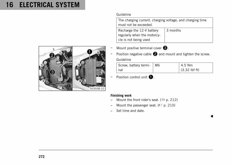
16 ELECTRICAL SYSTEM
272
Guideline
The charging current, charging voltage, and charging timemust not be exceeded.
Recharge the 12-V batteryregularly when the motorcy-cle is not being used
3 months
S03938-10
– Mount positive terminal cover3.
– Position negative cable2 and mount and tighten the screw.
Guideline
Screw, battery termi-nal
M6 4.5 Nm(3.32 lbf ft)
– Position control unit1.
Finishing work– Mount the front rider's seat. ( p. 212)
– Mount the passenger seat. ( p. 210)
– Set time and date.

ELECTRICAL SYSTEM 16
273
16.7 Changing the RACE-ON key battery
WarningRisk of injury Button cells may burst if misused.
Swallowing button cells leads to severe chemical burning and may result in death in under 2 hours.
– Keep button cells and the RACE-ON key out of the reach of children.
– Make sure the button cells can never be swallowed or ingested.
– Seek medical attention immediately if button cells are swallowed or ingested.
– Do not expose button cells to extreme temperatures or mechanical loads.
Permissible temperature −20 … 50 °C (−4 … 122 °F)
– Do not damage the RACE-ON key by e.g. cutting or squashing it.
– Do not use the RACE-ON key if the RACE-ON key is damaged or the battery compartment cannot beclosed.
– Replace the RACE-ON key battery with the type specified only.

16 ELECTRICAL SYSTEM
274
S01740-10
– Fold out the key bit of the RACE-ON key.
– Push lower half of the RACE-ON key in the direction of thearrow and take off.
S01739-10
– Remove battery cover1.
– Remove RACE-ON key battery2.
– Insert new the RACE-ON key battery with label facing upward.
RACE-ON key battery (CR 2032) ( p. 329)
– Mount battery cover1.

ELECTRICAL SYSTEM 16
275
S01740-11
– Fit lower half of the RACE-ON key and snap into place in thedirection of the arrow.
16.8 Changing the main fuse
WarningFire hazard Incorrect fuses overload the electrical system.
– Only use fuses with the required ampere value.
– Do not bypass or repair fuses.
Preparatory work– Remove the passenger seat. ( p. 209)
– Remove the front rider's seat. ( p. 211)

16 ELECTRICAL SYSTEM
276
S03939-10
Main work– Take off protection cap1.
S03940-10
– Remove faulty main fuse2.
InfoA faulty fuse has a burned-out fuse wireA.A spare fuse3 is located in the starter relay.The main fuse protects all electrical power consumersof the vehicle.
– Insert a new main fuse.
Fuse (58011109130) ( p. 329)
– Check that the electrical system is functioning properly.
– Mount protection caps1.

ELECTRICAL SYSTEM 16
277
TipInsert a new spare fuse into the starter relay to have itavailable when needed.
Finishing work– Mount the front rider's seat. ( p. 212)
– Mount the passenger seat. ( p. 210)
– Set time and date.
16.9 Changing the fuses in the fuse box
WarningFire hazard Incorrect fuses overload the electrical system.
– Only use fuses with the required ampere value.
– Do not bypass or repair fuses.
InfoThe fuse box containing the fuses of individual electrical power consumers is located under the seat.
Preparatory work– Remove the passenger seat. ( p. 209)
– Remove the front rider's seat. ( p. 211)

16 ELECTRICAL SYSTEM
278
S03941-10
Main work– Open fuse box cover1.
S03942-10
– Check the fuses.
InfoA faulty fuse has a burned-out fuse wireA.
– Remove the faulty fuse.

ELECTRICAL SYSTEM 16
279
Guideline
Fuse 1 - 10 A - power supply for control units and compo-nents
Fuse 2 - 10 A - ACC1
Fuse 3 - 10 A - license plate lamp, tail light
Fuse 4 - 10 A - permanent positive for headlight
Fuse 5 - 10 A - control unit
Fuse 6 - 25 A - ABS return pump
Fuse 7 - 10 A - ABS hydraulic unit
Fuse 8 - 10 A - ACC2, USB socket
Fuse 9 - not assigned
Fuse 10 - not assigned
Fuse res - 10 A - spare fuses
Fuse res - 15 A - spare fuse
Fuse res - 25 A - spare fuse
– Insert the spare fuse with the correct rating.
Fuse (58011109110) ( p. 329)
Fuse (58011109115) ( p. 329)
Fuse (58011109125) ( p. 329)

16 ELECTRICAL SYSTEM
280
TipInsert a spare fuse so that it is available if needed.
– Check the function of the electrical power consumers.
– Close the fuse box cover1.
Finishing work– Mount the front rider's seat. ( p. 212)
– Mount the passenger seat. ( p. 210)
16.10 Changing the turn signal bulb
NoteDamage to reflector Grease on the reflector reduces the light intensity.
Grease on the bulb will evaporate due to the heat and be deposited on the reflector.
– Clean and degrease the bulbs before mounting.
– Do not touch the bulbs with your bare hands.

ELECTRICAL SYSTEM 16
281
M01489-10
– Remove screw on the front of the turn signal housing.
– Carefully remove turn signal glass1.
– Press bulb2 carefully into the socket, turn it counterclock-wise by about 30°, and take it out of the socket.
InfoDo not touch the reflector with your fingers and keep itfree from grease.
– Push the new bulb gently into the socket and turn it clockwiseall the way in.
Turn signal (RY10W / socket BAU15s) ( p. 330)
– Check that the turn signal is functioning properly.
– Position the turn signal glass.
InfoInsert holding lugA into cut-outB.
– Insert the screw and first turn counterclockwise until itengages in the thread with a small jerk. Tighten the screwlightly.

16 ELECTRICAL SYSTEM
282
16.11 Checking the headlight setting
400726-10
– Park the vehicle on a horizontal surface in front of a light-colored wall and make a mark at the height of the center ofthe low beam headlight.
– Make another mark at a distanceB under the first marking.
Guideline
DistanceB 5 cm (2 in)
– Position the vehicle perpendicular to the wall at a distanceAfrom the wall and switch on the low beam.
Guideline
DistanceA 5 m (16 ft)
– The rider now mounts the motorcycle with luggage and passen-ger if applicable.
– Check the headlight setting.
The light-dark boundary must be exactly on the lower mark-ing when the motorcycle is ready to be operated with therider mounted along with any luggage and a passenger ifapplicable.
» If the boundary between light and dark does not meetspecifications:
– Adjust the headlight range. ( p. 283)

ELECTRICAL SYSTEM 16
283
16.12 Adjusting the headlight range
Preparatory work– Check the headlight setting. ( p. 282)
S03951-10
Main work– Turn adjusting screw1 to adjust the headlight range.
InfoTurn clockwise to increase the headlight range; turncounterclockwise to reduce the headlight range.If you have a payload, you may have to correct theheadlight range.Screw1 also secures the headlight. Ensure the screwis always screwed in far enough.
400726-11
– Set the headlight to markingB.
Guideline
The light-dark boundary must lie exactly on lower mark-ingB when the motorcycle is ready to operate with therider mounted along with any luggage and a passenger ifapplicable.

16 ELECTRICAL SYSTEM
284
16.13 Connecting the USB cable
InfoThe USB socket is located on the left of the combination instrument.
S03943-10
– Open USB socket cover1.
– Connect a suitable USB cable to the USB socket2.
– Connect the USB cable to the device.
– Route the cable on the handlebar and secure with the cableties.
Guideline
Use the shortest possible USB cable.
Always ensure that connected devices are also protectedagainst moisture.
Route and secure the cable in such a way that it cannot bedamaged.

ELECTRICAL SYSTEM 16
285
16.14 Disconnecting the USB cable
S03944-10
– Disconnect USB cable from the device.
– Disconnect USB cable from the USB socket1.
– Close USB socket cover2.
16.15 Diagnostics connector
H01949-01
Diagnostics connector1 is located under the front rider's seat.
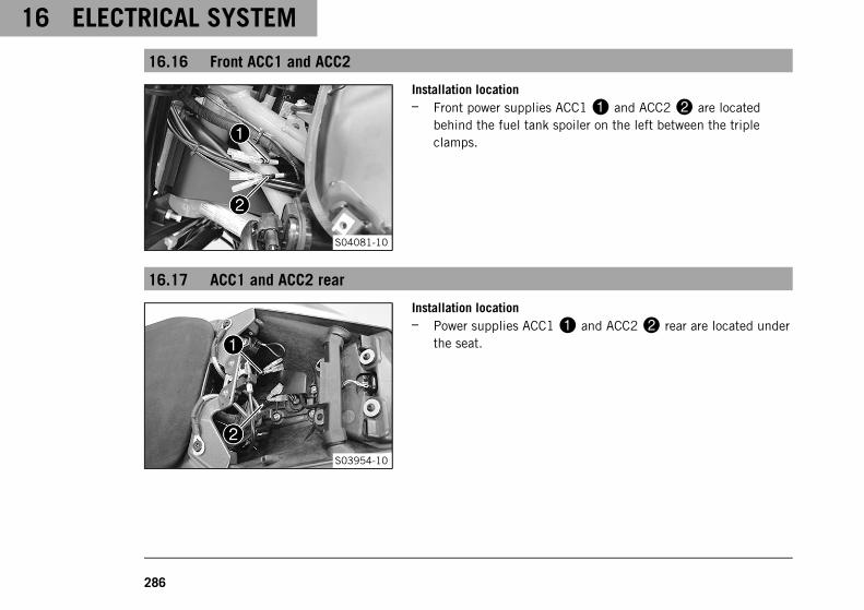
16 ELECTRICAL SYSTEM
286
16.16 Front ACC1 and ACC2
S04081-10
Installation location– Front power supplies ACC11 and ACC22 are located
behind the fuel tank spoiler on the left between the tripleclamps.
16.17 ACC1 and ACC2 rear
S03954-10
Installation location– Power supplies ACC11 and ACC22 rear are located under
the seat.

COOLING SYSTEM 17
287
17.1 Checking the coolant level in the compensating tank
WarningDanger of scalding During motorcycle operation, the coolant gets very hot and is under pressure.
– Do not open the radiator, the radiator hoses or other cooling system components if the engine or thecooling system are at operating temperature.
– Allow the cooling system and the engine to cool down before you open the radiator, the radiator hosesor other components of the cooling system.
– In the event of scalding, rinse the area affected immediately with lukewarm water.
WarningDanger of poisoning Coolant is toxic and a health hazard.
– Keep coolant out of the reach of children.
– Do not allow coolant to come into contact with the skin, the eyes and clothing.
– Consult a doctor immediately if coolant is swallowed.
– Rinse the affected area immediately with plenty of water in the event of contact with the skin.
– Rinse eyes thoroughly with water and consult a doctor immediately if coolant gets into the eyes.
– Change clothing if coolant spills onto your clothing.
ConditionThe engine is cold.The radiator is completely full.

17 COOLING SYSTEM
288
S03955-10
– Park the motorcycle on a horizontal surface.
– Check the coolant level in the compensating tank1.
The coolant level must be between MIN and MAX.
» If there is no coolant in the compensating tank:
– Check the cooling system for leaks.
InfoDo not start up the motorcycle!
– Add the coolant/bleed the cooling system.
» If the coolant in the compensating tank is not at therequired level, but the tank is not empty:
– Correct the coolant level in the compensating tank.( p. 289)

COOLING SYSTEM 17
289
17.2 Correcting the coolant level in the compensating tank
WarningDanger of scalding During motorcycle operation, the coolant gets very hot and is under pressure.
– Do not open the radiator, the radiator hoses or other cooling system components if the engine or thecooling system are at operating temperature.
– Allow the cooling system and the engine to cool down before you open the radiator, the radiator hosesor other components of the cooling system.
– In the event of scalding, rinse the area affected immediately with lukewarm water.
WarningDanger of poisoning Coolant is toxic and a health hazard.
– Keep coolant out of the reach of children.
– Do not allow coolant to come into contact with the skin, the eyes and clothing.
– Consult a doctor immediately if coolant is swallowed.
– Rinse the affected area immediately with plenty of water in the event of contact with the skin.
– Rinse eyes thoroughly with water and consult a doctor immediately if coolant gets into the eyes.
– Change clothing if coolant spills onto your clothing.
ConditionThe engine is cold.The radiator is completely full.
Preparatory work– Check the coolant level in the compensating tank. ( p. 287)
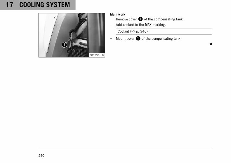
17 COOLING SYSTEM
290
S03956-10
Main work– Remove cover1 of the compensating tank.
– Add coolant to the MAX marking.
Coolant ( p. 346)
– Mount cover1 of the compensating tank.

ENGINE TUNING 18
291
18.1 Ride Mode
S03808-01
Possible states• TRACK – Optional setting available with homologated perfor-
mance and extremely direct response. The motorcycle tractioncontrol and the characteristic map of the throttle responsecan be individually set.
• PERFORMANCE – Optional setting available with homolo-gated performance and extremely direct response. The motor-cycle traction control and throttle response characteristicscan be individually adjusted and the KTM MY RIDE functioncan be used. Combines the functions of TRACK mode withstandard modes.
• SPORT – Homologated performance with very direct response;the motorcycle traction control allows greater slip on the rearwheel.
• STREET – Homologated performance with balanced response;the motorcycle traction control allows normal slip on the rearwheel.
• RAIN – Reduced homologated performance with soft responsefor improved rideability; the motorcycle traction control allowsless slip on the rear wheel.
Various vehicle tunings can be selected in the Ride Mode menu.There is TRACK (optional), PERFORMANCE (optional), SPORT,STREET and RAIN.The riding mode selected last appears in the display.

18 ENGINE TUNING
292
The riding mode can also be changed while riding with a closedthrottle grip and deactivated speed sensor.
InfoThe riding mode selection does not influence the ABS.
18.2 Motorcycle traction control (MTC)
S03805-01
The (cornering MTC) lowers the engine torque in case of loss oftraction in the rear wheel.
InfoWhen motorcycle traction control is switched off, the rearwheel may spin during strong acceleration and on surfaceswith low grip, resulting in a risk of falling.After the ignition is switched on, motorcycle traction con-trol is enabled again.
The motorcycle traction control is controlled via the Motorcycle( p. 291) menu on the combination instrument. The motorcycletraction control can be switched off in the MTC/ABS menu.

ENGINE TUNING 18
293
InfoWhen the motorcycle traction control is active, the TC indi-cator lamp flashes.When motorcycle traction control is switched off, theTC indicator lamp lights up.
18.3 Anti wheelie mode (optional)
S03827-01
The Anti Wheelie Mode is an optional vehicle electronics function.Anti wheelie mode is intended to prevent the front wheel risingwhen accelerating.

18 ENGINE TUNING
294
18.4 Slip adjustment (optional)
402790-01
The slip adjustment is an optional motorcycle traction controlfunction.The slip adjustment allows the motorcycle traction control to betuned through nine levels to the desired characteristic map.Level 1 allows the maximum slip on the rear wheel, and level 9the minimum.The slip adjustment can be set while riding with a closed menuusing the UP or DOWN button.
InfoThe slip adjustment is only availableif riding mode TRACK or PERFORMANCE ( p. 291)(optional) is active.
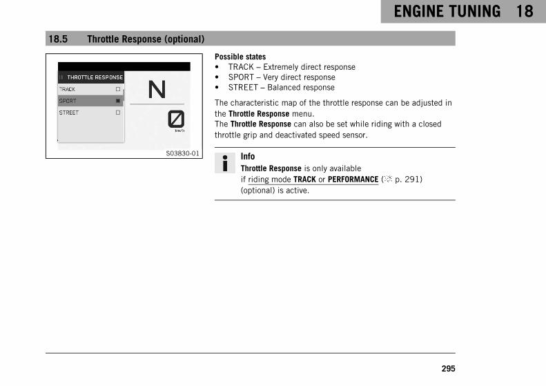
ENGINE TUNING 18
295
18.5 Throttle Response (optional)
S03830-01
Possible states• TRACK – Extremely direct response• SPORT – Very direct response• STREET – Balanced response
The characteristic map of the throttle response can be adjusted inthe Throttle Response menu.The Throttle Response can also be set while riding with a closedthrottle grip and deactivated speed sensor.
InfoThrottle Response is only availableif riding mode TRACK or PERFORMANCE ( p. 291)(optional) is active.

19 SERVICE WORK ON THE ENGINE
296
19.1 Checking the engine oil level
InfoOil consumption depends on the riding style and the operating conditions.
ConditionThe engine is at operating temperature.
Preparatory work– Stand the motorcycle upright on a horizontal surface.
S03957-10
Main work– Check the engine oil level in the engine oil level viewer.
InfoAfter switching off the engine, wait one minute beforechecking the level.
The engine oil level should be in the upper areaB of theengine oil level viewer.
» When the engine oil level is in areaA of the engine oillevel viewer:
– Do not add engine oil.
» When the engine oil level is in areaB of the engine oillevel viewer:
– Engine oil can be added.

SERVICE WORK ON THE ENGINE 19
297
» When the engine oil level is in areaC of the engine oillevel viewer:
– Add engine oil. ( p. 304)
19.2 Changing the engine oil and oil filter, cleaning the oil screens
WarningDanger of scalding Engine and gear oil get very hot when the motorcycle is ridden.
– Wear suitable protective clothing and safety gloves.
– In the event of scalding, rinse the area affected immediately with lukewarm water.
NoteEnvironmental hazard Hazardous substances cause environmental damage.
– Dispose of oils, grease, filters, fuel, cleaning agents, brake fluid, etc., correctly and in compliance withthe applicable regulations.

19 SERVICE WORK ON THE ENGINE
298
S03958-10
Main work– Stand the motorcycle on a level surface using the side stand.
– Place an appropriate container under the engine.
– In order to prevent oil from running over the exhaust system,use a mouldable funnel if necessary.
– Remove oil drain plugs1 along with the magnets, the O-rings, and the oil screens.
S03959-10
– Remove screws2. Take off oil filter cover3 with the O-ring.

SERVICE WORK ON THE ENGINE 19
299
S03960-10
– Pull oil filter4 out of the oil filter housing.
Lock ring plier (51012011000)
– Allow the engine oil to drain completely.
– Thoroughly clean the parts and the sealing surfaces.
S03961-10
– Insert new oil filter4.
InfoOnly insert the oil filter by hand.
– Oil the O-ring of the oil filter cover. Mount oil filter cover3.

19 SERVICE WORK ON THE ENGINE
300
S03959-11
– Mount and tighten screws2.
Guideline
Remaining enginescrews
M5 6 Nm (4.4 lbf ft)
100773-12
– Thoroughly clean magnetsA and oil screensB of the oildrain plugs.

SERVICE WORK ON THE ENGINE 19
301
S03958-10
– Mount and tighten oil drain plugs1 with magnets, O-rings,and oil screens.
Guideline
Oil drain plug M20x1.5 20 Nm (14.8 lbf ft)
S03962-10
– Have the entire filling quantity available.
Engine oilAmbienttemperature: ≥ 0 °C(≥ 32 °F)
3.50 l(3.7 qt.)
Engine oil(SAE 10W/50)( p. 347)
Engine oilAmbienttemperature: < 0 °C(< 32 °F)
Engine oil (SAE5W/40) ( p. 348)
– Add the oil quantity in two steps.
– Remove filler plug5 with the O-ring, and fill up with the firstpartial quantity.
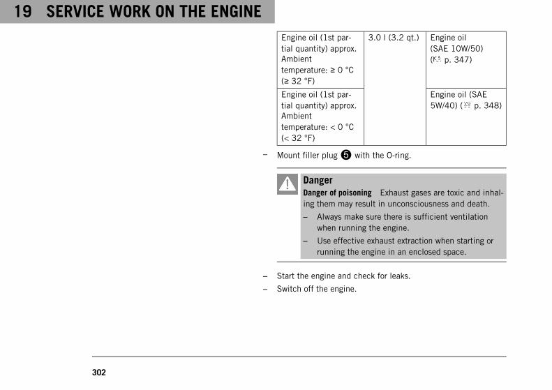
19 SERVICE WORK ON THE ENGINE
302
Engine oil (1st par-tial quantity) approx.Ambienttemperature: ≥ 0 °C(≥ 32 °F)
3.0 l (3.2 qt.) Engine oil(SAE 10W/50)( p. 347)
Engine oil (1st par-tial quantity) approx.Ambienttemperature: < 0 °C(< 32 °F)
Engine oil (SAE5W/40) ( p. 348)
– Mount filler plug5 with the O-ring.
DangerDanger of poisoning Exhaust gases are toxic and inhal-ing them may result in unconsciousness and death.
– Always make sure there is sufficient ventilationwhen running the engine.
– Use effective exhaust extraction when starting orrunning the engine in an enclosed space.
– Start the engine and check for leaks.
– Switch off the engine.

SERVICE WORK ON THE ENGINE 19
303
S03957-11
– Remove the filler plug with the O-ring and add the second par-tial quantity up to the upper markingC on the engine oillevel viewer.
Engine oil (2nd par-tial quantity) approx.Ambienttemperature: ≥ 0 °C(≥ 32 °F)
0.50 l(0.53 qt.)
Engine oil(SAE 10W/50)( p. 347)
Engine oil (2nd par-tial quantity) approx.Ambienttemperature: < 0 °C(< 32 °F)
Engine oil (SAE5W/40) ( p. 348)
– Mount the filler plug with the O-ring.
DangerDanger of poisoning Exhaust gases are toxic and inhal-ing them may result in unconsciousness and death.
– Always make sure there is sufficient ventilationwhen running the engine.
– Use effective exhaust extraction when starting orrunning the engine in an enclosed space.
– Start the engine and check for leaks.

19 SERVICE WORK ON THE ENGINE
304
Finishing work– Check the engine oil level. ( p. 296)
19.3 Adding engine oil
InfoToo little engine oil or poor-quality engine oil results in premature wear to the engine.The engine may be damaged if the engine oil level is too high.
ConditionThe engine is at operating temperature.
Preparatory work– Stand the motorcycle upright on a horizontal surface.
– Check the engine oil level. ( p. 296)
S03962-11
Main work– Remove filler plug1 with the O-ring.

SERVICE WORK ON THE ENGINE 19
305
S03957-12
– Add the engine oil to upper markingA on the engine oil levelviewer.
ConditionAmbient temperature: ≥ 0 °C (≥ 32 °F)
Engine oil (SAE 10W/50) ( p. 347)
ConditionAmbient temperature: < 0 °C (< 32 °F)
Engine oil (SAE 5W/40) ( p. 348)
InfoIn order to achieve optimal engine oil performance, it isnot advisable to mix different engine oils.KTM recommends changing the engine oil where neces-sary.
– Mount the filler plug with the O-ring.
DangerDanger of poisoning Exhaust gases are toxic and inhal-ing them may result in unconsciousness and death.
– Always make sure there is sufficient ventilationwhen running the engine.
– Use effective exhaust extraction when starting orrunning the engine in an enclosed space.
– Start the engine and check for leaks.

19 SERVICE WORK ON THE ENGINE
306
Finishing work– Check the engine oil level. ( p. 296)

CLEANING, CARE 20
307
20.1 Cleaning the motorcycle
NoteMaterial damage Components become damaged or destroyed if a pressure cleaner is used incorrectly.
The high pressure forces water into the electrical components, connectors, throttle cables, and bearings, etc.Pressure which is too high causes malfunctions and destroys components.
– Do not direct the water jet directly on to electrical components, connectors, throttle cables or bearings.
– Maintain a minimum distance between the nozzle of the pressure cleaner and the component.
Minimum clearance 60 cm (23.6 in)
NoteEnvironmental hazard Hazardous substances cause environmental damage.
– Dispose of oils, grease, filters, fuel, cleaning agents, brake fluid, etc., correctly and in compliance withthe applicable regulations.
InfoClean the motorcycle regularly to maintain its value and appearance over a long period.Avoid direct sunshine when cleaning the motorcycle.

20 CLEANING, CARE
308
401061-01
– Close off exhaust system to keep water from entering.
– Remove the coarse dirt particles with a gentle water jet.
– Spray the heavily soiled parts with a normal commercial motor-cycle cleaner and clean using a brush.
Motorcycle cleaner ( p. 350)
InfoUse warm water containing normal motorcycle cleanerand a soft sponge.Never apply motorcycle cleaner to a dry vehicle; alwaysrinse the vehicle with water first.If the vehicle has been used on salted roads, use coldwater for cleaning after riding. Warm water enhancesthe corrosive effects of salt.
– After rinsing the motorcycle with a gentle spray of water, allowit to dry thoroughly.
– Remove the closure of the exhaust system.
WarningDanger of accidents Moisture and dirt impair thebrake system.
– Brake carefully several times to dry out and removedirt from the brake linings and the brake discs.

CLEANING, CARE 20
309
– After cleaning, ride the vehicle a short distance until theengine warms up.
InfoThe heat produced causes water at inaccessible loca-tions in the engine and on the brake system to evapo-rate.
– After the motorcycle has cooled down, lubricate all movingparts and pivot points.
– Clean the chain. ( p. 222)
– Treat bare metal (except for brake discs and the exhaust sys-tem) with a corrosion inhibitor.
Preserving materials for paints, metal and rubber( p. 351)
– Treat the painted parts with a mild paint polish.
Perfect finish and high gloss polish for paints ( p. 350)
InfoDo not polish parts that were matte when delivered asthis would strongly impair the material quality.
– Treat the plastic parts and powder-coated parts with a mildcleaning agent and care product.

20 CLEANING, CARE
310
Special cleaner for glossy and matte paint finishes, metaland plastic surfaces ( p. 351)
– Oil steering lock and seat lock.
Universal oil spray ( p. 351)
20.2 Checks and maintenance steps for winter operation
InfoIf you use the motorcycle in winter, you must expect salt on the roads. You should therefore take precau-tions against aggressive road salt.If the vehicle has been used on salted roads, use cold water for cleaning after riding. Warm waterenhances the corrosive effects of salt.
401060-01
– Clean the motorcycle. ( p. 307)
– Clean the brakes.
InfoAfter EVERY trip on salted roads, thoroughly clean thebrake calipers and brake linings, after they have cooleddown and without removing them, with cold water anddry them carefully.After riding on salted roads, thoroughly clean themotorcycle with cold water and dry it well.

CLEANING, CARE 20
311
– Treat the engine, the link fork, and all other bare or zinc-platedparts (except the brake discs) with a wax-based corrosioninhibitor.
InfoCorrosion inhibitor must not come into contact withthe brake discs. This would severely lower the brakingeffect.
– Clean the chain. ( p. 222)

21 STORAGE
312
21.1 Storage
InfoIf the motorcycle is not being used for an extended length of time, additional measures are recommended.Before storing the motorcycle, check all parts for function and wear. If service, repairs, or replacementsare necessary, you should do this during the storage period (less workshop overload). This allows you toavoid long waiting periods when the next season starts.
401058-01
– When refueling for the last time before taking the motorcycleout of service, add fuel additive.
Fuel additive ( p. 350)
– Refuel. ( p. 182)
– Clean the motorcycle. ( p. 307)
– Change the engine oil and the oil filter, clean the oilscreens. ( p. 297)
– Check the coolant fill level and antifreeze.
– Check tire pressure. ( p. 260)
– Remove the 12-V battery. ( p. 264)
Guideline
Storage temperature of the12-V battery without directsunlight
0 … 35 °C (32 … 95 °F)
– Charge the 12-V battery. ( p. 269)

STORAGE 21
313
– Store the vehicle in a dry location that is not subject to largefluctuations in temperature.
InfoKTM recommends jacking up the motorcycle.
– Lift the motorcycle with the rear lifting gear. ( p. 201)
– Lift the motorcycle with the front lifting gear. ( p. 202)
– Cover the motorcycle with a tarp or cover that is permeable toair.
InfoDo not use non-porous materials since they preventhumidity from escaping, thus causing corrosion.Avoid running the engine for a short time only. Sincethe engine cannot warm up properly, the water vaporproduced during combustion condenses and causesvalves and the exhaust system to rust.

21 STORAGE
314
21.2 Preparing for use after storage
401059-01
– Take the motorcycle off the front lifting gear. ( p. 203)
– Remove the rear of the motorcycle from the lifting gear.( p. 201)
– Install the 12-V battery. ( p. 266)
InfoIf the 12-V battery was removed, the time and datemust be set.
– Perform checks and maintenance measures when preparing foruse. ( p. 162)
– Take a test ride.

TROUBLESHOOTING 22
315
S03841-10
The RACE-ON indicator lamp1 can indicate errors by flashing.These are indicated up to five seconds after the RACE‑ON buttonis actuated.
InfoBlink codes referring to KTM RACE ON are only displayedonce and not repeated.
Faults Possible cause Action
No response if the RACE-ONbutton is pressed
RACE-ON button faulty – Check the RACE-ON button for dam-age.
– Check the cable and the plug of theRACE-ON button for damage.

22 TROUBLESHOOTING
316
Faults Possible cause Action
RACE-ON indicator lampflashes twice
No response signal from theRACE-ON key
– Ensure that the RACE-ON key is inrange.
– Remove other electronic devices fromthe vicinity of the RACE-ON antenna.
– Check the battery compartment in theRACE-ON key for correct locking.
– Check the battery compartment of theRACE-ON key for corrosion.
– Change the RACE-ON key battery.( p. 273)
– Use black ignition key.
RACE-ON indicator lampflashes three times
12-V battery discharged – Charge the 12-V battery. ( p. 269)
– Check the open-circuit current.
RACE-ON indicator lampflashes four times
Steering lock bolt locked ortense
– Move handlebar slightly.
RACE-ON indicator lampflashes five times
RACE-ON antenna faulty – Check the RACE-ON antenna for dam-age.
The combination instrumentshows nothing on the display
Fuse 1 is blown – Change the fuses in the fuse box.( p. 277)
The main fuse is blown – Change the main fuse. ( p. 275)
12-V battery discharged – Charge the 12-V battery. ( p. 269)
– Check the open-circuit current.

TROUBLESHOOTING 22
317
Faults Possible cause Action
Engine does not rotate if thestart button/emergency OFFswitch is pressed into the lowerposition
Operating error – Carry out start procedure. ( p. 163)
12-V battery discharged – Charge the 12-V battery. ( p. 269)
– Check the open-circuit current.
Faulty safety starting system – Read out the fault memory using theKTM diagnostics tool.
Electronic fault – Read out the fault memory using theKTM diagnostics tool.
The engine only turns if theclutch lever is drawn
The vehicle is in gear – Shift the transmission into neutral.
Faulty safety starting system – Read out the fault memory using theKTM diagnostics tool.
The engine turns although agear is engaged
Faulty safety starting system – Read out the fault memory using theKTM diagnostics tool.
The engine turns but does notstart
Quick release coupling notjoined
– Join the quick release coupling.
Error in the electronic fuelinjection
– Read out the fault memory using theKTM diagnostics tool.
The fuel quality is insufficient – Add suitable fuel.
The engine dies during the trip Lack of fuel – Refuel. ( p. 182)
Error in the electronic fuelinjection
– Read out the fault memory using theKTM diagnostics tool.
Malfunction indicator lamplights up or flashes
Error in the electronic fuelinjection
– Read out the fault memory using theKTM diagnostics tool.

22 TROUBLESHOOTING
318
Faults Possible cause Action
The ABS warning lamp lightsup
ABS fuse blown – Change the fuses in the fuse box.( p. 277)
Large difference in wheelspeeds of the front and rearwheels
– Stop the vehicle, switch off the igni-tion, and start it again.
Malfunction in ABS – Read out the fault memory using theKTM diagnostics tool.
High oil consumption The engine oil level is too high – Check the engine oil level. ( p. 296)
The engine oil is too thin (lowviscosity)
– Change the engine oil and the oil filter,clean the oil screens. ( p. 297)
12-V battery discharged The hazard warning flasher isswitched on
– Switch off the hazard warning flasher.
– Charge the 12-V battery. ( p. 269)
The 12-V battery is not beingcharged by the alternator
– Check the charging voltage.
The ignition was not switchedoff while the vehicle wasparked
– Charge the 12-V battery. ( p. 269)

TECHNICAL DATA 23
319
23.1 Engine
Design 2-cylinder 4-stroke Otto engine, 75° V arrangement,water-cooled
Displacement 1,301 cm³ (79.39 cu in)
Stroke 71 mm (2.8 in)
Bore 108 mm (4.25 in)
Compression ratio 13.5:1
Idle speed 1,400 … 1,600 rpm
Control DOHC, 4 valves per cylinder, chain-driven
Valve - valve plate diameter
Intake 42 mm (1.65 in)
Exhaust 34 mm (1.34 in)
Valve clearance
Intake at: 20 °C (68 °F) 0.10 … 0.15 mm (0.0039 … 0.0059 in)
Exhaust at: 20 °C (68 °F) 0.25 … 0.30 mm (0.0098 … 0.0118 in)
Crankshaft bearing Sleeve bearing
Conrod bearing Sleeve bearing
Piston Forged light alloy
Piston ring 1 upper compression (rectangular) ring, 1 lower com-pression ring, 1 oil scraper ring
Engine lubrication Dry sump lubrication system with 3 trochoidal pumps

23 TECHNICAL DATA
320
Primary transmission 40:76
Clutch Antihopping clutch in oil bath/hydraulically operated
Transmission 6-gear transmission, claw shifted
Transmission ratio
1st gear 12:35
2nd gear 15:32
3rd gear 18:30
4th gear 20:27
5th gear 24:27
6th gear 27:26
Mixture preparation Electronic fuel injection
Ignition system Contactless controlled fully electronic ignition withdigital ignition adjustment
Alternator 12 V, 450 W
Spark plug
Inside spark plug NGK LKAR9BI‑10
Outside spark plug NGK LMAR7DI‑10
Electrode gap, spark plug 1 mm (0.04 in)
Cooling Water cooling, permanent circulation of coolant bywater pump
Cold start device Starter motor

TECHNICAL DATA 23
321
23.2 Engine tightening torques
Screw, damping plate EJOT ALtracs® M6x14 10 Nm (7.4 lbf ft)Loctite®243™
Screw, retaining bracket, valvecover, rear
EJOT® M6x12 8 Nm (5.9 lbf ft)
Hose clip, intake flange M4 1.5 Nm (1.11 lbf ft)
Oil nozzle M5 2 Nm (1.5 lbf ft)Loctite®243™
Remaining engine screws M5 6 Nm (4.4 lbf ft)
Screw, bearing retainer M5 5 Nm (3.7 lbf ft)Loctite®243™
Screw, bearing shells retainingbracket
M5 6 Nm (4.4 lbf ft)Loctite®243™
Screw, cable duct on the enginefixing arm
M5 5 Nm (3.7 lbf ft)
Screw, crankshaft speed sensor M5 6 Nm (4.4 lbf ft)Loctite®243™
Screw, engine oil level viewer M5 4 Nm (3 lbf ft)Loctite®243™
Screw, gear position sensor M5 5 Nm (3.7 lbf ft)Loctite®243™
Screw, oil filter cover M5 6 Nm (4.4 lbf ft)

23 TECHNICAL DATA
322
Screw, resonator M5 8 Nm (5.9 lbf ft)Loctite®243™
Screw, shift shaft sensor M5 5 Nm (3.7 lbf ft)Loctite®243™
Bleeder screw, cylinder head M6 6 Nm (4.4 lbf ft)
Bleeder screw, water pump cover M6 10 Nm (7.4 lbf ft)
Coolant connection screw on thecylinder head
M6 8 Nm (5.9 lbf ft)Loctite®243™
Freewheel ring bolt M6 – 10.9 15 Nm (11.1 lbf ft)Loctite® 648™
Nut, cylinder head M6 8 Nm (5.9 lbf ft)
Remaining engine screws M6 10 Nm (7.4 lbf ft)
Screw, alternator cover M6 10 Nm (7.4 lbf ft)
Screw, camshaft bearing support M6 – 10.9 10 Nm (7.4 lbf ft)
Screw, clutch cover M6 10 Nm (7.4 lbf ft)
Screw, clutch spring M6 12 Nm (8.9 lbf ft)
Screw, engine case M6x60 10 Nm (7.4 lbf ft)
Screw, engine case M6x80 10 Nm (7.4 lbf ft)
Screw, engine case M6x90 10 Nm (7.4 lbf ft)
Screw, guide rail M6 10 Nm (7.4 lbf ft)Loctite®243™
Screw, heat exchanger M6 10 Nm (7.4 lbf ft)Loctite®243™
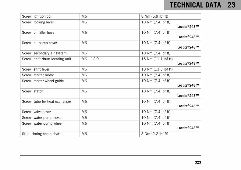
TECHNICAL DATA 23
323
Screw, ignition coil M6 8 Nm (5.9 lbf ft)
Screw, locking lever M6 10 Nm (7.4 lbf ft)Loctite®243™
Screw, oil filler hose M6 10 Nm (7.4 lbf ft)Loctite®243™
Screw, oil pump cover M6 10 Nm (7.4 lbf ft)Loctite®243™
Screw, secondary air system M6 10 Nm (7.4 lbf ft)
Screw, shift drum locating unit M6 – 12.9 15 Nm (11.1 lbf ft)Loctite®243™
Screw, shift lever M6 18 Nm (13.3 lbf ft)
Screw, starter motor M6 10 Nm (7.4 lbf ft)
Screw, starter wheel guide M6 10 Nm (7.4 lbf ft)Loctite®243™
Screw, stator M6 10 Nm (7.4 lbf ft)Loctite®243™
Screw, tube for heat exchanger M6 10 Nm (7.4 lbf ft)Loctite®243™
Screw, valve cover M6 10 Nm (7.4 lbf ft)
Screw, water pump cover M6 10 Nm (7.4 lbf ft)
Screw, water pump wheel M6 10 Nm (7.4 lbf ft)Loctite®243™
Stud, timing chain shaft M6 3 Nm (2.2 lbf ft)

23 TECHNICAL DATA
324
Vacuum connection M6 2.5 Nm (1.84 lbf ft)Loctite®243™
Nozzle 100 M6x0.75 2 Nm (1.5 lbf ft)Loctite®243™
Oil nozzle for clutch lubrication M6x0.75 2 Nm (1.5 lbf ft)
Crankshaft locking bolt M8 12 Nm (8.9 lbf ft)
Screw, camshaft bearing support M8 – 10.9 Step 110 Nm (7.4 lbf ft)Step 218 Nm (13.3 lbf ft)
Screw, camshaft bearing support M8 – 10.9 Step 18.5 Nm (6.27 lbf ft)Step 214.5 Nm (10.7 lbf ft)Only applies when using:Hexagon socket bit(61229025000)
Screw, engine case M8 18 Nm (13.3 lbf ft)
Screw, guide rail M8 15 Nm (11.1 lbf ft)Loctite®243™
Screw, tensioning rail M8 15 Nm (11.1 lbf ft)Loctite®243™
Stud, exhaust flange M8 10 Nm (7.4 lbf ft)
Screw, engine bearer M10 45 Nm (33.2 lbf ft)

TECHNICAL DATA 23
325
Oil pressure sensor M10x1 15 Nm (11.1 lbf ft)
Screw plug, cam lever axis M10x1 12 Nm (8.9 lbf ft)
Screw plug, clutch lubrication M10x1 8 Nm (5.9 lbf ft)
Screw plug, spreading transmis-sion lock
M10x1 12 Nm (8.9 lbf ft)
Screw, conrod bearing M10x1 Step 125 Nm (18.4 lbf ft)Step 230 Nm (22.1 lbf ft)Step 390°
Screw, unlocking of timing chaintensioner
M10x1 8 Nm (5.9 lbf ft)
Spark plug outside M10x1 11 Nm (8.1 lbf ft)
Coolant temperature sensor M10x1.25 12 Nm (8.9 lbf ft)

23 TECHNICAL DATA
326
Cylinder head screw M11x1.5 Tightening sequence:Using a crisscross patternStep 115 Nm (11.1 lbf ft)Step 230 Nm (22.1 lbf ft)Step 390°Step 490°
Lubricated with engine oil
Screw, shock absorber bell crank M12 80 Nm (59 lbf ft)
Rotor screw M12x1.5 115 Nm (84.8 lbf ft)
Spark plug inside M12x1.5 18 Nm (13.3 lbf ft)
Nut of engine sprocket M20x1.5 100 Nm (73.8 lbf ft)Loctite®243™
Oil drain plug M20x1.5 20 Nm (14.8 lbf ft)
Nut, inner clutch hub M22x1.5 140 Nm (103.3 lbf ft)
Plug, timing-chain tensioner M24x1.5 25 Nm (18.4 lbf ft)
Screw plug, alternator cover M24x1.5 8 Nm (5.9 lbf ft)
Nut, primary gear wheel M33LHx1.5 130 Nm (95.9 lbf ft)Loctite®243™

TECHNICAL DATA 23
327
23.3 Capacities
23.3.1 Engine oil
Engine oilAmbient temperature: ≥ 0 °C(≥ 32 °F)
3.50 l (3.7 qt.) Engine oil (SAE 10W/50)( p. 347)
Engine oilAmbient temperature: < 0 °C(< 32 °F)
Engine oil (SAE 5W/40) ( p. 348)
23.3.2 Coolant
Coolant 3.20 l (3.38 qt.) Coolant ( p. 346)
23.3.3 Fuel
Total fuel tank capacity, approx. 16 l (4.2 US gal) Super unleaded (ROZ 95)( p. 349)
Fuel reserve, approx. 3.5 l (3.7 qt.)

23 TECHNICAL DATA
328
23.4 Chassis
Frame Lattice frame made of chrome molybdenum steel tub-ing, powder-coated
Fork WP SuspensionAPEX 5548
Shock absorber WP SuspensionAPEX 5746
Suspension travel
front 125 mm (4.92 in)
rear 140 mm (5.51 in)
Brake system
front Double disc brake with radially mounted four-pistonbrake calipers, floating brake discs
rear Single disc brake with dual-piston brake caliper, fixedbrake disc
Brake discs - diameter
front 320 mm (12.6 in)
rear 240 mm (9.45 in)
Brake discs - wear limit
front 4.5 mm (0.177 in)
rear 4.5 mm (0.177 in)
Tire pressure when solo
front: with cold tires 2.5 bar (36 psi)

TECHNICAL DATA 23
329
rear: with cold tires 2.5 bar (36 psi)
Secondary drive ratio 17:38
Chain 5/8 x 5/16” (525) X‑ring
Steering head angle 64.8°
Wheelbase 1,497 mm (58.94 in)
Seat height unloaded 835 mm (32.87 in)
Ground clearance unloaded 160 mm (6.3 in)
Weight without fuel approx. 198 kg (437 lb.)
Maximum permissible front axle load 165 kg (364 lb.)
Maximum permissible rear axle load 260 kg (573 lb.)
Maximum permissible overall weight 425 kg (937 lb.)
23.5 Electrical system
12-V battery YTX14-BS Battery voltage: 12 VNominal capacity: 12 AhMaintenance-free
RACE-ON key battery CR 2032 3 V
Fuse 58011109110 10 A
Fuse 58011109115 15 A
Fuse 58011109125 25 A
Fuse 58011109130 30 A

23 TECHNICAL DATA
330
Low beam/high beam LED
Daytime running light/position light LED
Combination instrument lightingand indicator lamps
LED
Turn signal RY10W / socket BAU15s 12 V10 W
Tail light LED
Brake light LED
License plate lamp LED
23.6 Tires
Front tire Rear tire
120/70 ZR 17 M/C (58W) TLBridgestone Battlax Hypersport S22 F
200/55 ZR 17 M/C (75W) TLBridgestone Battlax Hypersport S22 R
The tires specified represent one of the possible series production tires. Additional information is available inthe Service section under:http://www.ktm.com
23.7 Fork
Fork article number 14.18.8T.22
Fork WP SuspensionAPEX 5548

TECHNICAL DATA 23
331
Compression damping
Comfort 21 clicks
Standard 15 clicks
Sport 7 clicks
Full payload 7 clicks
Rebound damping
Comfort 21 clicks
Standard 15 clicks
Sport 7 clicks
Full payload 7 clicks
Spring length with preload spacer(s) 303 mm (11.93 in)
Spring rate
Soft 8.5 N/mm (48.5 lb/in)
Medium (standard) 9 N/mm (51 lb/in)
Hard 9.5 N/mm (54.2 lb/in)
Fork length 753 mm (29.65 in)
Fork oil per fork leg 615 ± 15 ml (20.79± 0.51 fl. oz.)
Fork oil (SAE 4) (48601166S1)( p. 348)

23 TECHNICAL DATA
332
23.8 Shock absorber
Shock absorber article number 15.18.7T.22
Shock absorber WP SuspensionAPEX 5746
Low-speed compression damping
Comfort 21 clicks
Standard 12 clicks
Sport 7 clicks
Full payload 7 clicks
High-speed compression damping
Comfort 1.5 turns
Standard 1.5 turns
Sport 1 turn
Full payload 1 turn
Rebound damping
Comfort 21 clicks
Standard 15 clicks
Sport 10 clicks
Full payload 10 clicks
Spring preload

TECHNICAL DATA 23
333
Standard 8 mm (0.31 in)
InfoCorresponds to position 0 on the preloadadjuster.
Spring rate
Weight of rider: 65 … 75 kg (143 … 165 lb.) 75 N/mm (428 lb/in)
Weight of rider: 75 … 85 kg (165 … 187 lb.) 85 N/mm (485 lb/in)
Weight of rider: 85 … 95 kg (187 … 209 lb.) 95 N/mm (542 lb/in)
Spring length 195 mm (7.68 in)
Gas pressure 10 bar (145 psi)
Static sag 20 mm (0.79 in)
Riding sag 45 mm (1.77 in)
Fitted length 356 mm (14.02 in)
Shock absorber fluid ( p. 348) SAE 2.5
23.9 Chassis tightening torques
Brake fluid reservoir for front brakecover
‑ 1 Nm (0.7 lbf ft)
Brake fluid reservoir for rear brakecover
‑ 3.5 Nm (2.58 lbf ft)
Remaining screws, chassis EJOT PT® K50x12 1 Nm (0.7 lbf ft)

23 TECHNICAL DATA
334
Remaining screws, chassis EJOT PT® K50x14 1 Nm (0.7 lbf ft)
Remaining screws, chassis EJOT PT® K50x16 2 Nm (1.5 lbf ft)
Remaining screws, chassis EJOT PT® K50x18 2 Nm (1.5 lbf ft)
Remaining screws, chassis EJOT PT® K45x12 1 Nm (0.7 lbf ft)
Screw, air filter box cover EJOT PT® K60x30 2.5 Nm (1.84 lbf ft)
Screw, ball head holder on head-light
EJOT ALtracs® 50x12 7 Nm (5.2 lbf ft)
Screw, brake assembly 5 Nm (3.7 lbf ft)
Screw, exhaust valve cover fasten-ing
EJOT SF® M4x6‑K 4 Nm (3 lbf ft)
Screw, intake air temperature sen-sor
EJOT PT® K50x16 2 Nm (1.5 lbf ft)
Screw, radiator fan cover EJOT DELTA PT® 40x46/10 1 Nm (0.7 lbf ft)
Screw, SAS on air filter box EJOT PT® K50x16 2 Nm (1.5 lbf ft)
Screw, tail light EJOT PT® K50x14 2.5 Nm (1.84 lbf ft)
Screw, fixed grip, left M4 3 Nm (2.2 lbf ft)
Screw, side stand sensor M4 2 Nm (1.5 lbf ft)
Remaining nuts, chassis M5 5 Nm (3.7 lbf ft)
Remaining screws, chassis M5 5 Nm (3.7 lbf ft)
Screw for throttle grip M5 3.5 Nm (2.58 lbf ft)
Screw, 6D sensor holder M5 2.7 Nm (1.99 lbf ft)Loctite®243™

TECHNICAL DATA 23
335
screw, absorbing element, combi-nation instrument
M5 2 Nm (1.5 lbf ft)Loctite®243™
Screw, cable channel M5 5 Nm (3.7 lbf ft)
Screw, chain sliding guard M5 5 Nm (3.7 lbf ft)
Screw, combination instrument M5 1 Nm (0.7 lbf ft)
Screw, combination switch, left M5 5 Nm (3.7 lbf ft)
Screw, combination switch, right M5 5 Nm (3.7 lbf ft)
Screw, front turn signal bracket M5 3.5 Nm (2.58 lbf ft)
Screw, fuel level sensor M5 3 Nm (2.2 lbf ft)
Screw, fuel tank filler cap M5 3 Nm (2.2 lbf ft)
Screw, fuel tank spoiler M5 2.5 Nm (1.84 lbf ft)
Screw, headlight locking cap M5 3.5 Nm (2.58 lbf ft)
Screw, heat guard on main silencer M5 4 Nm (3 lbf ft)
Screw, injection valve M5 4 Nm (3 lbf ft)Loctite®243™
Screw, intake trumpet M5 6 Nm (4.4 lbf ft)
Screw, radiator fan cover M5 3.5 Nm (2.58 lbf ft)
Screw, rear turn signal bracket M5 3.5 Nm (2.58 lbf ft)
Screw, trim M5 3.5 Nm (2.58 lbf ft)
Screw, wiring harness holdingbracket
M5 3.5 Nm (2.58 lbf ft)

23 TECHNICAL DATA
336
Cable disk nut, exhaust valve con-trol unit
M6 14 Nm (10.3 lbf ft)
Ground fitting on frame M6 10 Nm (7.4 lbf ft)
Remaining nuts, chassis M6 10 Nm (7.4 lbf ft)
Remaining screws, chassis M6 10 Nm (7.4 lbf ft)
Screw, 6D sensor M6 6 Nm (4.4 lbf ft)
Screw, ABS module fastening M6 8 Nm (5.9 lbf ft)
Screw, ball joint of push rod onfoot brake cylinder
M6 5 Nm (3.7 lbf ft)Loctite®243™
Screw, battery holder M6 6 Nm (4.4 lbf ft)
Screw, battery terminal M6 4.5 Nm (3.32 lbf ft)
Screw, cable on starter relay M6 6 Nm (4.4 lbf ft)
Screw, clutch assembly M6 5 Nm (3.7 lbf ft)Loctite®243™
Screw, cooler retaining bracket M6 7 Nm (5.2 lbf ft)
Screw, engine sprocket cover M6 8 Nm (5.9 lbf ft)
Screw, exhaust clamp on mainsilencer
M6 10 Nm (7.4 lbf ft)
Screw, foot brake cylinder M6 10 Nm (7.4 lbf ft)Loctite®243™
Screw, front fuel tank M6 8 Nm (5.9 lbf ft)
Screw, front wheel speed sensor M6 4 Nm (3 lbf ft)

TECHNICAL DATA 23
337
Screw, fuel pump M6 6 Nm (4.4 lbf ft)
Screw, fuel tank bridge M6 8 Nm (5.9 lbf ft)
Screw, fuel tank cover M6 5 Nm (3.7 lbf ft)
Screw, fuel tank spoiler M6 6 Nm (4.4 lbf ft)
Screw, fuse box support M6 6 Nm (4.4 lbf ft)
Screw, fuse box support M6 6 Nm (4.4 lbf ft)
Screw, headlight on retainingbracket
M6 5 Nm (3.7 lbf ft)
Screw, instrument support M6 2 Nm (1.5 lbf ft)
Screw, license plate holder onlower rear panel
M6 8 Nm (5.9 lbf ft)
Screw, presilencer exhaust clamp M6 10 Nm (7.4 lbf ft)
Screw, radiator bracket M6 5 Nm (3.7 lbf ft)
Screw, radiator hose clip M6 3 Nm (2.2 lbf ft)
Screw, rear wheel speed sensor M6 4 Nm (3 lbf ft)
Screw, seat lock M6 5 Nm (3.7 lbf ft)Loctite®243™
Screw, shift lever stub M6 10 Nm (7.4 lbf ft)
Screw, shift rod M6 5 Nm (3.7 lbf ft)Loctite®243™
Screw, shift shaft deflector on shiftshaft
M6 18 Nm (13.3 lbf ft)Loctite®243™

23 TECHNICAL DATA
338
Screw, steering damper bracket onframe
M6 8 Nm (5.9 lbf ft)Loctite®243™
Screw, step plate for foot brakelever
M6 10 Nm (7.4 lbf ft)
Screw, voltage regulator M6 6 Nm (4.4 lbf ft)
Nut, exhaust valve throttle cable M6x1 5 Nm (3.7 lbf ft)
Cable disk nut, exhaust valve M8 7 Nm (5.2 lbf ft)
Nut, rear sprocket M8 36 Nm (26.6 lbf ft)Loctite®243™
Nut, shift rod M8 12 Nm (8.9 lbf ft)
Nut, valve M8 6 Nm (4.4 lbf ft)Loctite®243™
Remaining nuts, chassis M8 25 Nm (18.4 lbf ft)
Remaining screws, chassis M8 25 Nm (18.4 lbf ft)
Screw, axle clamp M8 15 Nm (11.1 lbf ft)
Screw, bottom triple clamp M8 15 Nm (11.1 lbf ft)
Screw, cross connector on lowerrear panel
M8 15 Nm (11.1 lbf ft)
Screw, foot brake lever M8 20 Nm (14.8 lbf ft)Loctite®243™
Screw, front brake disc M8 28 Nm (20.7 lbf ft)Loctite®2701™

TECHNICAL DATA 23
339
Screw, front rider footrest bracket M8 25 Nm (18.4 lbf ft)Loctite®243™
Screw, handlebar clamp M8 20 Nm (14.8 lbf ft)
Screw, ignition lock (tamper-proofscrew)
M8 25 Nm (18.4 lbf ft)
Screw, passenger footrest unit M8x25 25 Nm (18.4 lbf ft)Loctite®243™
Screw, passenger footrest unit M8x35 25 Nm (18.4 lbf ft)Loctite®243™
Screw, rear brake caliper M8 25 Nm (18.4 lbf ft)Loctite®2701™
Screw, rear brake disc M8 28 Nm (20.7 lbf ft)Loctite®243™
Screw, shift lever on footrestbracket
M8 20 Nm (14.8 lbf ft)Loctite®243™
Screw, side stand bracket M8 25 Nm (18.4 lbf ft)Loctite®243™
Screw, side stand spring M8 15 Nm (11.1 lbf ft)Loctite®2701™
Screw, steering damper on holder M8 8 Nm (5.9 lbf ft)Loctite®243™
Screw, steering damper on tripleclamp
M8 8 Nm (5.9 lbf ft)Loctite®243™

23 TECHNICAL DATA
340
Screw, steering stem clamp M8 20 Nm (14.8 lbf ft)Loctite®243™
Screw, subframe M8 35 Nm (25.8 lbf ft)Loctite®243™
Screw, subframe brace M8 25 Nm (18.4 lbf ft)Loctite®243™
Screw, subframe metal flange M8 25 Nm (18.4 lbf ft)Loctite®243™
Screw, top triple clamp M8 18 Nm (13.3 lbf ft)
Remaining nuts, chassis M10 45 Nm (33.2 lbf ft)
Remaining screws, chassis M10 45 Nm (33.2 lbf ft)
Screw, engine bearer M10 45 Nm (33.2 lbf ft)Loctite®243™
Screw, front brake caliper M10 45 Nm (33.2 lbf ft)Loctite®243™
Screw, handlebar support M10 40 Nm (29.5 lbf ft)Loctite®243™
Screw, side stand M10 40 Nm (29.5 lbf ft)Loctite®243™
Banjo bolt, brake line M10x1 25 Nm (18.4 lbf ft)
Banjo bolt, brake line, connectingpiece, rear
M10x1 25 Nm (18.4 lbf ft)
Nut, rear hub shock absorber car-rier
M10x1.25 45 Nm (33.2 lbf ft)Loctite®243™

TECHNICAL DATA 23
341
Screw, bottom shock absorber M12 80 Nm (59 lbf ft)Loctite®243™
Screw, brake caliper support M12 28 Nm (20.7 lbf ft)
Screw, side stand bracket M12 80 Nm (59 lbf ft)Loctite®243™
Screw, top shock absorber M12 80 Nm (59 lbf ft)Loctite®243™
Screw, triangular lever on link fork M12 80 Nm (59 lbf ft)Loctite®243™
Lambda sensor M12x1.25 24.5 Nm (18.07 lbf ft)
Screw, eccentric M16 70 Nm (51.6 lbf ft)
Nut, fork pivot M19x1.5 130 Nm (95.9 lbf ft)Thread greased
Screw, shock absorber support M20x1.5 10 Nm (7.4 lbf ft)Thread and fitting greased
Screw, steering head, top M20x1.5 12 Nm (8.9 lbf ft)
Nut, seat lock M22x1.5 3 Nm (2.2 lbf ft)
Screw, front wheel spindle M25x1.5 45 Nm (33.2 lbf ft)Thread greased
Nut, rear axle, shock absorber side M35x1.5 200 Nm (147.5 lbf ft)Loctite® 262™/lock the locking wire
with locking varnish
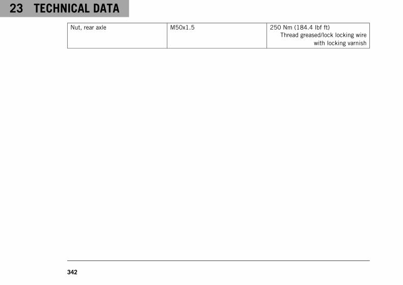
23 TECHNICAL DATA
342
Nut, rear axle M50x1.5 250 Nm (184.4 lbf ft)Thread greased/lock locking wire
with locking varnish

DECLARATIONS OF CONFORMITY 24
343
24.1 Declarations of conformity
InfoThe functional and equipment scope is model-dependent and may not include all wireless systems andapplication areas referred to.
Connectivity Control Unit "CCU‑2"FCC ID: 2AOW7-K001IC: 5966A-K001
KTM RACE ON system ‑ Active KeyFCC ID: VFZKLGKZADI01IC: 22239-KLGKZADI01
KTM RACE ON system ‑ Main UnitFCC ID: VFZKLGMZADI01IC: 22239-KLGMZADI01
Tyre Pressure Monitoring System ‑ Receiver "MC34MA4"FCC ID: MRXMC34MA4IC: 2546A-MC34MA4
Tyre Pressure Monitoring System ‑ Sensor "RDC3"FCC ID: MRXRDC3IC: 2546A-RDC3
Declaration regarding modificationsAlterations and modifications not expressly approved by the relevant authority may result in the user being prohib-ited from operating the equipment.

24 DECLARATIONS OF CONFORMITY
344
Declaration regarding interferenceThis device fulfills Part 15 of the FCC regulations as well as the license-free RSS standards of the Canadian Gov-ernment Department Industry Canada.Operation is subject to the following two conditions:
1 This device must not cause interference.
2 This device must be able to absorb any interference, including interference that potentially causes undesir-able operation of the device.
Note on radio transmissionsThis device corresponds to the FCC limit values for radiation exposure, which have been determined for a non-controlled environment, and fulfills the FCC guidelines for the load from radio frequencies.The transmitter must not be set up near to other antennas or transmitters or operated in conjunction with otherantennas or transmitters.
Note on digital devices of Class B according to the FCC regulationsThis device has been tested and fulfills the limit values for digital devices of Class B according to the FCC regula-tions, Part 15.These limit values are designed so as to provide sufficient protection from harmful interference in residentialareas.Devices of this type generate and use high frequencies and can also emit these. Therefore, if they are notinstalled and operated in accordance with the instructions, they may cause harmful interference to radioreception. However, there is no guarantee that interference will not occur in certain cases of application.Should this device cause harmful interference to radio or television reception, (check this by switching the deviceon and off), you can potentially eliminate this interference as follows:

DECLARATIONS OF CONFORMITY 24
345
– Re-align the receiving antenna.
– Increase the separation between device and radio receiver.
– Connect the device and the radio receiver to separate electric circuits.
– Consult your dealer or a radio/TV technician.
CAN ICES‑3 (B) / NMB‑3 (B)This digital device of Class B fulfills the regulations in accordance with the Canadian Interference-Causing Equip-ment Standard ICES‑003 / NMB‑003.

25 SUBSTANCES
346
Brake fluid DOT 4 / DOT 5.1Standard/classification– DOT
Guideline– Use only brake fluid that complies with the specified standard (see specifications on the container) and that
exhibits the corresponding properties.
Recommended supplierCastrol– REACT PERFORMANCE DOT 4
MOTOREX®
– Brake Fluid DOT 5.1
CoolantGuideline– Only use high-grade, silicate-free coolant with corrosion inhibitor additive for aluminum motors. Low grade
and unsuitable antifreeze causes corrosion, deposits and frothing.
– Do not use pure water as only coolant is able to meet the requirements needed in terms of corrosion protec-tion and lubrication properties.
– Only use coolant that complies with the requirements stated (see specifications on the container) and thathas the relevant properties.
Antifreeze protection to at least −25 °C (−13 °F)

SUBSTANCES 25
347
The mixture ratio must be adjusted to the necessary antifreeze protection. Use distilled water if the coolant needsto be diluted.
The use of premixed coolant is recommended.
Observe the coolant manufacturer specifications for antifreeze protection, dilution and miscibility (compatibility)with other coolants.
Recommended supplierMOTOREX®
– COOLANT M3.0
Engine oil (SAE 10W/50)Standard/classification– JASO T903 MA2 ( p. 352)
– SAE ( p. 352) (SAE 10W/50)
Guideline– Use only engine oils that comply with the specified standards (see specifications on the container) and that
possess the corresponding properties.
Fully synthetic engine oil
Recommended supplierMOTOREX®
– Power Synt 4T

25 SUBSTANCES
348
Engine oil (SAE 5W/40)Standard/classification– JASO T903 MA2 ( p. 352)
– SAE ( p. 352) (SAE 5W/40)
Guideline– Use only engine oils that comply with the specified standards (see specifications on the container) and that
possess the corresponding properties.
Fully synthetic engine oil
Recommended supplierMOTOREX®
– Power Synt 4T
Fork oil (SAE 4) (48601166S1)Standard/classification– SAE ( p. 352) (SAE 4)
Guideline– Use only oils that comply with the specified standards (see specifications on the container) and that exhibit
the corresponding properties.
Shock absorber fluid (SAE 2.5) (50180751S1)Standard/classification– SAE ( p. 352) (SAE 2.5)

SUBSTANCES 25
349
Guideline– Use only oils that comply with the specified standards (see specifications on the container) and that exhibit
the corresponding properties.
Super unleaded (ROZ 95)Standard/classification– DIN EN 228 (ROZ 95)
Guideline– Only use super unleaded fuel that matches or is equivalent to the specified standard.
– Fuel with an ethanol content of up to 10% (E10 fuel) is safe to use.
InfoDo not use fuel containing methanol (e.g., M15, M85, M100) or more than 10% ethanol (e.g., E15,E25, E85, E100).
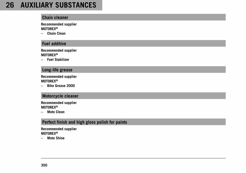
26 AUXILIARY SUBSTANCES
350
Chain cleanerRecommended supplierMOTOREX®
– Chain Clean
Fuel additiveRecommended supplierMOTOREX®
– Fuel Stabilizer
Long-life greaseRecommended supplierMOTOREX®
– Bike Grease 2000
Motorcycle cleanerRecommended supplierMOTOREX®
– Moto Clean
Perfect finish and high gloss polish for paintsRecommended supplierMOTOREX®
– Moto Shine

AUXILIARY SUBSTANCES 26
351
Preserving materials for paints, metal and rubberRecommended supplierMOTOREX®
– Moto Protect
Special cleaner for glossy and matte paint finishes, metal and plastic surfacesRecommended supplierMOTOREX®
– Quick Cleaner
Street chain sprayGuideline
Recommended supplierMOTOREX®
– Chainlube Road Strong
Universal oil sprayRecommended supplierMOTOREX®
– Joker 440 Synthetic

27 STANDARDS
352
JASO T903 MA2Different technical development directions required a separate specification for motorcycles – the JASO T903 MA2standard.Earlier, engine oils from the automobile industry were used for motorcycles because there was no separate motor-cycle specification.Whereas long service intervals are demanded for automobile engines, the focus for motorcycle engines is on highperformance at high engine speeds.In most motorcycle engines, the transmission and clutch are lubricated with the same oil.The JASO T903 MA2 standard meets these special requirements.
SAEThe SAE viscosity classes were defined by the Society of Automotive Engineers and are used for classifying oilsaccording to their viscosity. The viscosity describes only one property of oil and says nothing about quality.

INDEX OF SPECIAL TERMS 28
353
ABS Anti-lock braking system Safety system that prevents locking of the wheelswhen driving straight ahead without the influence oflateral forces
ATIR Automatic Turn Indicator Reset Software, which automatically switches the indicatoroff according to a time or travel distance counter
DRL Daytime Running Light Light, which enhances the visibility of the vehicle dur-ing the day but is not focused, and in contrast to lowbeam does not illuminate the road surface
ETTC Engine traction torque control Auxiliary function of the engine control, which pre-vents rear wheel locking with excessive engine brakingeffect, by lightly opening the throttle valve
- KTM RACE ON System that releases the ignition, steering lock, andfuel tank filler cap via a remote key with a transponder
- Launch control Vehicles electronics functions for achieving the bestpossible acceleration from a standing position
MSC Motorcycle Stability Control The is an auxiliary function for the ABS, which canprevent blocking and slipping of the wheels duringbraking on an inclined position, within the physicallimitations
Cornering MTC Motorcycle Traction Control Auxiliary function of the motor control that reducesengine torque with spinning rear wheel
OBD On-board diagnosis Vehicle system, which monitors the specified parame-ters of the vehicle electronics

28 INDEX OF SPECIAL TERMS
354
- Quickshifter + Engine electronics function for shifting up and downwithout clutch actuation
TPMS Tire pressure monitoring system A safety system that monitors the tire pressure withthe assistance of sensors in the tires and displays it tothe rider

LIST OF ABBREVIATIONS 29
355
Art. no. Article number
ca. circa
cf. compare
e.g. for example
etc. et cetera
i.a. inter alia
no. number
poss. possibly

30 LIST OF SYMBOLS
356
30.1 Red symbols
Red symbols indicate an error condition that requires immediate intervention.
The oil pressure warning lamp lights up red – The oil pressure is too low. Stop immediately,taking care not to endanger yourself or other road users in the process, and switch off theengine.
30.2 Yellow and orange symbols
Yellow and orange symbols indicate an error condition that requires prompt intervention. Active driving aids arealso represented by yellow or orange symbols.
RACE-ON indicator lamp lights up/flashes yellow/red – Status or error messages relating toRace-on system/alarm system.
The general warning lamp lights up yellow – A note/warning note on operating safety has beendetected. This is also shown in the display.
The ABS warning lamp lights up yellow – Status or error messages relating to ABS. When ABSSupermoto mode is activated, SM is shown in the display.
TC indicator lamp lights up/flashes yellow – The MTC ( p. 292) is not active, is currentlyintervening or a Launch Control Start is being executed. The TC indicator lamp also lights upif an error is detected. Contact an authorized KTM workshop. The TC indicator lamp flashes ifthe motorcycle traction control actively engages.
The cruise control system indicator lamp lights up yellow – The cruise control system functionis switched on, but cruise control is not activated.

LIST OF SYMBOLS 30
357
Malfunction indicator lamp lights up yellow – The OBD has detected an error in the vehicleelectronics.
30.3 Green and blue symbols
Green and blue symbols reflect information.
The left turn signal indicator lamp flashes green with a steady rhythmic flash – The left turnsignal is switched on.
The high beam indicator lamp lights up blue – The high beam is switched on.
The cruise control system indicator lamp lights up green – The cruise control system functionis switched on and cruise control is activated.
The right turn signal indicator lamp flashes green with a steady rhythmic flash – The right turnsignal is switched on.

INDEX
358
INDEX
+
+RES/-SET buttonoperation . . . . . . . . . . . . . . . . . . . . . . . . . . 46
1
12-V batterycharging . . . . . . . . . . . . . . . . . . . . . . . . . 269installing . . . . . . . . . . . . . . . . . . . . . . . . . 266removing . . . . . . . . . . . . . . . . . . . . . . . . . 264
A
ABS . . . . . . . . . . . . . . . . . . . . . . . . . . . . . . . 235
ACC1front . . . . . . . . . . . . . . . . . . . . . . . . . . . . 286rear . . . . . . . . . . . . . . . . . . . . . . . . . . . . 286
ACC2front . . . . . . . . . . . . . . . . . . . . . . . . . . . . 286rear . . . . . . . . . . . . . . . . . . . . . . . . . . . . 286
Accessories . . . . . . . . . . . . . . . . . . . . . . . . . . . 28Anti wheelie mode . . . . . . . . . . . . . . . . . . . . . 293Anti-lock braking system . . . . . . . . . . . . . . . . . 235Applying the brakes . . . . . . . . . . . . . . . . . . . . . 176Auxiliary substances . . . . . . . . . . . . . . . . . . . . . 28
B
Brake discschecking . . . . . . . . . . . . . . . . . . . . . . . . . 238
Brake fluidfront brake, adding . . . . . . . . . . . . . . . . . . 240of rear brake, adding . . . . . . . . . . . . . . . . . 245
Brake fluid levelfront brake, checking . . . . . . . . . . . . . . . . 239rear brake, checking . . . . . . . . . . . . . . . . . 244
Brake liningsfront brake, checking . . . . . . . . . . . . . . . . 243rear brake, checking . . . . . . . . . . . . . . . . . 248
Brake system . . . . . . . . . . . . . . . . . . . . . . 235-248Brakes . . . . . . . . . . . . . . . . . . . . . . . . . . . . . 176
C
C1 and C2 switch . . . . . . . . . . . . . . . . . . . . . . . 51
CapacityCoolant . . . . . . . . . . . . . . . . . . . . . . . . . . 327engine oil . . . . . . . . . . . . . . . . . . . . 301, 327fuel . . . . . . . . . . . . . . . . . . . . . . . . 184, 327
Chainchecking . . . . . . . . . . . . . . . . . . . . . . . . . 227cleaning . . . . . . . . . . . . . . . . . . . . . . . . . 222

INDEX
359
dirt, checking for . . . . . . . . . . . . . . . . . . . 222
Chain guidechecking . . . . . . . . . . . . . . . . . . . . . . . . . 227
Chain tensionadjusting . . . . . . . . . . . . . . . . . . . . . . . . . 226checking . . . . . . . . . . . . . . . . . . . . . . . . . 224
Clutchfluid level, checking/correcting . . . . . . . . . . 232
Clutch lever . . . . . . . . . . . . . . . . . . . . . . . . . . . 38basic position, adjusting . . . . . . . . . . . . . . 145
Combination instrument . . . . . . . . . . . . . . . . 62-142ABS . . . . . . . . . . . . . . . . . . . . . . . . . . . . 116ABS display . . . . . . . . . . . . . . . . . . . . . . . . 84activation and test . . . . . . . . . . . . . . . . . . . 63adjusting tilt . . . . . . . . . . . . . . . . . . . . . . 154ambient air temperature indicator . . . . . . . . . 88Anti Wheelie Mode . . . . . . . . . . . . . . . . . . . 111Audio . . . . . . . . . . . . . . . . . . . . . . . . . . . . 92Bluetooth . . . . . . . . . . . . . . . . . . . . . . . . . 119Button Illumination . . . . . . . . . . . . . . . . . . . 122C1 and C2 buttons . . . . . . . . . . . . . . . . . . 118Consumption . . . . . . . . . . . . . . . . . . . . . . . 131coolant temperature indicator . . . . . . . . . . . . 87cruise control indicator . . . . . . . . . . . . . . . . 83
day-night mode . . . . . . . . . . . . . . . . . . . . . 65Daytime Runn. Light . . . . . . . . . . . . . . . . . . 124display . . . . . . . . . . . . . . . . . . . . . . . . . . . 72Display Theme . . . . . . . . . . . . . . . . . . . . . . 121Distance . . . . . . . . . . . . . . . . . . . . . . . . . 128engine speed . . . . . . . . . . . . . . . . . . . . . . . 82Extra Functions . . . . . . . . . . . . . . . . . . . . . 107FAVORITES widget . . . . . . . . . . . . . . . . . . 138Favourites display . . . . . . . . . . . . . . . . . . . . 89fuel level display . . . . . . . . . . . . . . . . . . . . 87gear display . . . . . . . . . . . . . . . . . . . . . . . . 85General Info . . . . . . . . . . . . . . . . . . . . . . . 104Headset Type . . . . . . . . . . . . . . . . . . . . . . 120heated grip (optional) . . . . . . . . . . . . . . . . . 86Heated Grips (optional) . . . . . . . . . . . . 113, 133Heated Seat (optional) . . . . . . . . . . . . 114, 134HEATING widget . . . . . . . . . . . . . . . . . . . 140ice warning . . . . . . . . . . . . . . . . . . . . . . . . 67indicator lamps . . . . . . . . . . . . . . . . . . . . . 68KTM MY RIDE widget . . . . . . . . . . . . . . . . 136KTM MY RIDE . . . . . . . . . . . . . . . . . . . . . . . 91Language . . . . . . . . . . . . . . . . . . . . . . . . . 132large widget . . . . . . . . . . . . . . . . . . . . 80, 135Launch Control . . . . . . . . . . . . . . . . . . . . . 112menu . . . . . . . . . . . . . . . . . . . . . . . . . . . . 91

INDEX
360
Motorcycle . . . . . . . . . . . . . . . . . . . . . . . . 113MTC+MSR (optional) . . . . . . . . . . . . . . . . . 115MUSIC widget . . . . . . . . . . . . . . . . . . . . . 141navigation . . . . . . . . . . . . . . . . . . . . . . . . . 94navigation information . . . . . . . . . . . . . . . . . 95NAVIGATION widget . . . . . . . . . . . . . . . . . 137Navigation display . . . . . . . . . . . . . . . . . . . . 90odometer . . . . . . . . . . . . . . . . . . . . . . . . . . 81overview . . . . . . . . . . . . . . . . . . . . . . . . . . 62Pairing . . . . . . . . . . . . . . . . . . . . . . . . . . . 98performance layout (optional) . . . . . . . . . . . . 76Pressure . . . . . . . . . . . . . . . . . . . . . . . . . 130Quickshifter + (optional) . . . . . . . . . . . . . . . 117Ride display . . . . . . . . . . . . . . . . . . . . . . . . 85Ride Mode . . . . . . . . . . . . . . . . . . . . 108, 291seat heater (optional) . . . . . . . . . . . . . . . . . 86Service . . . . . . . . . . . . . . . . . . . . . . . . . . 107Settings . . . . . . . . . . . . . . . . . . . . . . . . . . 117shift warning light . . . . . . . . . . . . . . . . . . . . 82slip adjustment . . . . . . . . . . . . . . . . . . . . 294small widget . . . . . . . . . . . . . . . . . . . 78, 135speed . . . . . . . . . . . . . . . . . . . . . . . . . . . . 84telephony . . . . . . . . . . . . . . . . . . . . . . . . 101Temperature . . . . . . . . . . . . . . . . . . . . . . . 129Throttle Response . . . . . . . . . . . . . . . 110, 295
time . . . . . . . . . . . . . . . . . . . . . . . . . . . . . 89TPMS . . . . . . . . . . . . . . . . . . . . . . . . . . . 105Track . . . . . . . . . . . . . . . . . . . . . . . . . . . 109TRACK Display (optional) . . . . . . . . . . . . . . . 74Trip 1 . . . . . . . . . . . . . . . . . . . . . . . . . . . 102Trip 2 . . . . . . . . . . . . . . . . . . . . . . . . . . . 103Units . . . . . . . . . . . . . . . . . . . . . . . . . . . . 127volume . . . . . . . . . . . . . . . . . . . . . . . . . . . 96warnings . . . . . . . . . . . . . . . . . . . . . . 66, 106widget INFO . . . . . . . . . . . . . . . . . . . . . . 139
Combination switchleft side . . . . . . . . . . . . . . . . . . . . . . . . . . 39right . . . . . . . . . . . . . . . . . . . . . . . . . . . . . 47
Coolant levelcompensating tank, checking . . . . . . . . . . . 287correcting in the compensating tank . . . . . . 289
Cruise control systemoperation . . . . . . . . . . . . . . . . . . . . . . . . . . 43
Customer service . . . . . . . . . . . . . . . . . . . . . . . 29
D
Dateadjusting . . . . . . . . . . . . . . . . . . . . . . . . . 125
Daytime running light . . . . . . . . . . . . . . . . . . . . 263

INDEX
361
Declarations of conformity . . . . . . . . . . . . . 343-345Diagnostics connector . . . . . . . . . . . . . . . . . . . 285Driving . . . . . . . . . . . . . . . . . . . . . . . . . . . . . 169DRL . . . . . . . . . . . . . . . . . . . . . . . . . . . . . . . 263
E
Emergency OFF switch . . . . . . . . . . . . . . . . . . . . 49
Enginerunning in . . . . . . . . . . . . . . . . . . . . . . . . 159
Engine number . . . . . . . . . . . . . . . . . . . . . . . . . 36
Engine oiladding . . . . . . . . . . . . . . . . . . . . . . . . . . 304changing . . . . . . . . . . . . . . . . . . . . . . . . . 297
Engine oil levelchecking . . . . . . . . . . . . . . . . . . . . . . . . . 296
Engine sprocketchecking . . . . . . . . . . . . . . . . . . . . . . . . . 227
Engine traction torque control . . . . . . . . . . . . . . 175Environment . . . . . . . . . . . . . . . . . . . . . . . . . . . 26
F
Figures . . . . . . . . . . . . . . . . . . . . . . . . . . . . . . 29
Foot brake lever . . . . . . . . . . . . . . . . . . . . . . . . 60setting the step plate . . . . . . . . . . . . . . . . 147
Footrestsadjusting . . . . . . . . . . . . . . . . . . . . . . . . . 150
Fork . . . . . . . . . . . . . . . . . . . . . . . . . . . . . . . 190compression damping, adjusting . . . . . . . . . 191rebound, adjusting . . . . . . . . . . . . . . . . . . 193spring preload, adjusting . . . . . . . . . . . . . . 190
Fork legsbleeding . . . . . . . . . . . . . . . . . . . . . . . . . 194dust boots, cleaning . . . . . . . . . . . . . . . . . 207
Fork part number . . . . . . . . . . . . . . . . . . . . . . . 36
Front rider’s seatmounting . . . . . . . . . . . . . . . . . . . . . . . . 212removing . . . . . . . . . . . . . . . . . . . . . . . . . 211
Front wheelinstalling . . . . . . . . . . . . . . . . . . . . . . . . . 251removing . . . . . . . . . . . . . . . . . . . . . . . . . 249
Fuel tank filler capclosing . . . . . . . . . . . . . . . . . . . . . . . . . . . 56opening . . . . . . . . . . . . . . . . . . . . . . . . . . . 54
Fuel tank spoiler, leftinstalling . . . . . . . . . . . . . . . . . . . . . . . . . 215removing . . . . . . . . . . . . . . . . . . . . . . . . . 213
Fuel, oils, etc. . . . . . . . . . . . . . . . . . . . . . . . . . 28

INDEX
362
Fusesin fuse box, changing . . . . . . . . . . . . . . . . 277
H
Hand brake lever . . . . . . . . . . . . . . . . . . . . . . . 38basic position, adjusting . . . . . . . . . . . . . . 146
Handlebar position . . . . . . . . . . . . . . . . . . . . . 143adjusting . . . . . . . . . . . . . . . . . . . . . . . . . 143
Hazard warning flasher . . . . . . . . . . . . . . . . . . . 48Hazard warning flasher switch . . . . . . . . . . . . . . . 48
Headlightdaytime running light . . . . . . . . . . . . . . . . 263high beam . . . . . . . . . . . . . . . . . . . . . . . . 262low beam . . . . . . . . . . . . . . . . . . . . . . . . 262range, adjusting . . . . . . . . . . . . . . . . . . . . 283
Headlight settingchecking . . . . . . . . . . . . . . . . . . . . . . . . . 282
High beam . . . . . . . . . . . . . . . . . . . . . . . . . . . 262Horn button . . . . . . . . . . . . . . . . . . . . . . . . . . . 43
I
Ice warning . . . . . . . . . . . . . . . . . . . . . . . . . . . 67Immobilizer . . . . . . . . . . . . . . . . . . . . . . . . . . . 52Implied warranty . . . . . . . . . . . . . . . . . . . . . . . . 28Indicator lamps . . . . . . . . . . . . . . . . . . . . . . . . 68
Intended use . . . . . . . . . . . . . . . . . . . . . . . . . . 13
K
Key number . . . . . . . . . . . . . . . . . . . . . . . . . . . 35
L
Labelsoverview . . . . . . . . . . . . . . . . . . . . . . . . . . 16
Launch Control . . . . . . . . . . . . . . . . . . . . . . . . 166Light switch . . . . . . . . . . . . . . . . . . . . . . . . . . . 40Luggage . . . . . . . . . . . . . . . . . . . . . . . . . . . . 159
M
Main fusechanging . . . . . . . . . . . . . . . . . . . . . . . . . 275
Main silencerinstalling . . . . . . . . . . . . . . . . . . . . . . . . . 220removing . . . . . . . . . . . . . . . . . . . . . . . . . 218
Manufacturer warranty . . . . . . . . . . . . . . . . . . . . 28Menu buttons . . . . . . . . . . . . . . . . . . . . . . . . . . 41Misuse . . . . . . . . . . . . . . . . . . . . . . . . . . . . . . 13
Motorcyclecleaning . . . . . . . . . . . . . . . . . . . . . . . . . 307lifting with front lifting gear . . . . . . . . . . . . 202lifting with rear lifting gear . . . . . . . . . . . . . 201
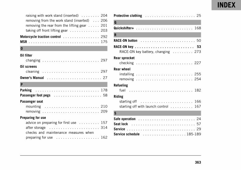
INDEX
363
raising with work stand (inserted) . . . . . . . . 204removing from the work stand (inserted) . . . 206removing the rear from the lifting gear . . . . . 201taking off front lifting gear . . . . . . . . . . . . . 203
Motorcycle traction control . . . . . . . . . . . . . . . . 292MSR . . . . . . . . . . . . . . . . . . . . . . . . . . . . . . . 175
O
Oil filterchanging . . . . . . . . . . . . . . . . . . . . . . . . . 297
Oil screenscleaning . . . . . . . . . . . . . . . . . . . . . . . . . 297
Owner's Manual . . . . . . . . . . . . . . . . . . . . . . . . 27
P
Parking . . . . . . . . . . . . . . . . . . . . . . . . . . . . 178Passenger foot pegs . . . . . . . . . . . . . . . . . . . . . 58
Passenger seatmounting . . . . . . . . . . . . . . . . . . . . . . . . 210removing . . . . . . . . . . . . . . . . . . . . . . . . . 209
Preparing for useadvice on preparing for first use . . . . . . . . . 157after storage . . . . . . . . . . . . . . . . . . . . . . 314checks and maintenance measures whenpreparing for use . . . . . . . . . . . . . . . . . . . 162
Protective clothing . . . . . . . . . . . . . . . . . . . . . . 25
Q
Quickshifter+ . . . . . . . . . . . . . . . . . . . . . . . . . 168
R
RACE-ON button . . . . . . . . . . . . . . . . . . . . . . . . 50
RACE-ON key . . . . . . . . . . . . . . . . . . . . . . . . . . 53RACE-ON key battery, changing . . . . . . . . . 273
Rear sprocketchecking . . . . . . . . . . . . . . . . . . . . . . . . . 227
Rear wheelinstalling . . . . . . . . . . . . . . . . . . . . . . . . . 255removing . . . . . . . . . . . . . . . . . . . . . . . . . 254
Refuelingfuel . . . . . . . . . . . . . . . . . . . . . . . . . . . . 182
Ridingstarting off . . . . . . . . . . . . . . . . . . . . . . . 166starting off with launch control . . . . . . . . . . 167
S
Safe operation . . . . . . . . . . . . . . . . . . . . . . . . . 24Seat lock . . . . . . . . . . . . . . . . . . . . . . . . . . . . 57Service . . . . . . . . . . . . . . . . . . . . . . . . . . . . . . 29Service schedule . . . . . . . . . . . . . . . . . . . 185-189

INDEX
364
Shift lever . . . . . . . . . . . . . . . . . . . . . . . . . . . . 59basic position, checking . . . . . . . . . . . . . . 148
Shift lever stubadjusting . . . . . . . . . . . . . . . . . . . . . . . . . 149
Shifting . . . . . . . . . . . . . . . . . . . . . . . . . . . . 169
Shock absorber . . . . . . . . . . . . . . . . . . . . . . . 190compression damping, general . . . . . . . . . . 195high-speed compression damping, adjusting . 198low-speed compression damping, adjusting . 196rebound damping, adjusting . . . . . . . . . . . . 199spring preload, adjusting . . . . . . . . . . . . . . 196
Shock absorber article number . . . . . . . . . . . . . . 37Side stand . . . . . . . . . . . . . . . . . . . . . . . . . . . . 60Slip adjustment . . . . . . . . . . . . . . . . . . . . . . . 294Spare parts . . . . . . . . . . . . . . . . . . . . . . . . . . . 28Start button . . . . . . . . . . . . . . . . . . . . . . . . . . . 49Starting . . . . . . . . . . . . . . . . . . . . . . . . . . . . 163Steering damper article number . . . . . . . . . . . . . . 37Steering lock . . . . . . . . . . . . . . . . . . . . . . . . . . 51Stopping . . . . . . . . . . . . . . . . . . . . . . . . . . . . 178Storage . . . . . . . . . . . . . . . . . . . . . . . . . . . . 312Supporting strap . . . . . . . . . . . . . . . . . . . . . . . . 58Suspension setting . . . . . . . . . . . . . . . . . . 190-200
T
Technical datacapacities . . . . . . . . . . . . . . . . . . . . . . . . 327chassis . . . . . . . . . . . . . . . . . . . . . . . . . . 328chassis tightening torques . . . . . . . . . . . . . 333electrical system . . . . . . . . . . . . . . . . . . . 329engine . . . . . . . . . . . . . . . . . . . . . . . . . . 319engine tightening torques . . . . . . . . . . . . . 321fork . . . . . . . . . . . . . . . . . . . . . . . . . . . . 330shock absorber . . . . . . . . . . . . . . . . . . . . . 332tires . . . . . . . . . . . . . . . . . . . . . . . . . . . . 330
Throttle grip . . . . . . . . . . . . . . . . . . . . . . . . . . . 39
Timeadjusting . . . . . . . . . . . . . . . . . . . . . . . . . 125
Tire conditionchecking . . . . . . . . . . . . . . . . . . . . . . . . . 257
Tire pressurechecking . . . . . . . . . . . . . . . . . . . . . . . . . 260
Tire repair sprayusing . . . . . . . . . . . . . . . . . . . . . . . . . . . 261
Tool set . . . . . . . . . . . . . . . . . . . . . . . . . . . . . 57Transporting . . . . . . . . . . . . . . . . . . . . . . . . . 180Troubleshooting . . . . . . . . . . . . . . . . . . . . 315-318

INDEX
365
Turn signal bulbchanging . . . . . . . . . . . . . . . . . . . . . . . . . 280
Turn signal switch . . . . . . . . . . . . . . . . . . . . . . . 42Type label . . . . . . . . . . . . . . . . . . . . . . . . . . . . 34
U
USB cableconnecting . . . . . . . . . . . . . . . . . . . . . . . 284disconnecting . . . . . . . . . . . . . . . . . . . . . 285
Use definition . . . . . . . . . . . . . . . . . . . . . . . . . 13
V
Vehicleloading . . . . . . . . . . . . . . . . . . . . . . . . . . 159
Vehicle identification number . . . . . . . . . . . . . . . 34
View of vehiclefront left . . . . . . . . . . . . . . . . . . . . . . . . . . 30rear right . . . . . . . . . . . . . . . . . . . . . . . . . . 32
W
Winter operationchecks and maintenance steps . . . . . . . . . . 310
Work rules . . . . . . . . . . . . . . . . . . . . . . . . . . . 26

*3214305en*3214305en
11/2020
KTM Sportmotorcycle GmbH5230 Mattighofen/Austriahttp://www.ktm.com
Photo:Mitterbauer/KISKA/KTM