2.1 horizontal hold down clamps series section - destaco.de€¦ · horizontal hold down clamps...
TRANSCRIPT

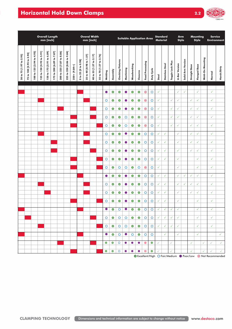
Horizontal Hold Down Clamps
www.destaco.com CLAMPING TECHNOLOGYDimensions and technical information are subject to change without notice
2.1
0 t
o 1
000 [
0 t
o 2
25]
1000 t
o 2
000 [
225 t
o 4
50]
2000 t
o 3
000 [
450 t
o 6
75]
3000 t
o 5
000 [
675 t
o 1
125]
5000 t
o 7
000 [
1125 t
o 1
575]
7000
to
1000
0 [1
575
to 2
250]
0 t
o 1
0 [
0 t
o 0
.39]
10 t
o 2
0 [
0.3
9 t
o 0
.79]
20 t
o 3
0 [
0.7
9 t
o 1
.18]
30 t
o 4
0 [
1.1
8 t
o 1
.57]
40 t
o 5
0 [
1.5
7 t
o 1
.97]
50 t
o 6
0 [
1.9
7 t
o 2
.36]
0 t
o 2
5 [
0 t
o 0
.98]
25 t
o 4
0 [
0.9
8 t
o 1
.57]
40 t
o 5
5 [
1.5
7 t
o 2
.17]
55 t
o 7
0 [
1.5
7 t
o 2
.76]
70 t
o 8
5 [
2.7
6 t
o 3
.35]
85 t
o 1
00 [
3.3
5 t
o 3
.94]
100+
[1.5
7+
]
2005
2013
2017
2027
2037
213
2.3
2.5
2.7
2.9
2.11
2.13
2.15
2.17
2.19
2.21
2.23
2.25
2.27
2.29
2.31
2.31
2.33
217
227
237
245
205
215
225
235
305
307
309
206
2.355305
2.355310
2.31
Max. Holding CapacityN[lbf.]
Overall Heightmm [inch]
Height UnderClamping Bar
mm [inch]
Seri
es
Sect
ion
.Pa
ge
UK 2 2010 Horizontal Clamping_Layout 1 07.09.12 13:29 Seite 1
Horizontal Hold Down Clamps
www.destaco.comCLAMPING TECHNOLOGY Dimensions and technical information are subject to change without notice
2. 2
50 t
o 7
5 [
1.9
7 t
o 2
.95]
75 t
o 1
00 [
2.9
5 t
o 3
.94]
100 t
o 1
25 [
3.9
4 t
o 4
.92]
125 t
o 1
50 [
4.9
2 t
o 5
.91]
150 t
o 1
75 [
5.9
1 t
o 6
.89]
175 t
o 2
00 [
6.8
9 t
o 7
.87]
200 t
o 2
25 [
7.8
7 t
o 8
.86]
225 t
o 2
50 [
8.8
6 t
o 9
.84]
250+
[9.8
4+
]
0 t
o 2
5 [
0 t
o 0
.98]
25 t
o 4
0 [
0.9
8 t
o 1
.57]
40 t
o 5
5 [
1.5
7 t
o 2
.17]
55 t
o 7
0 [
1.5
7 t
o 2
.76]
Weld
ing
Ass
em
bly
Ch
eck
ing
Fix
ture
s
Ma
chin
ing
Wood
work
ing
Clo
sure
s
Food
Pro
cess
ing
Du
ty C
ycle
Steel
Sta
inle
ss S
teel
Tog
gle
Lock
Plu
s
U-B
ar
Vers
ion
Solid
Arm
Vers
ion
Stra
igh
t B
ase
Fla
ng
ed
Ba
se
Weld
-On
Mou
nti
ng
Norm
al
Ha
rsh
/Dir
ty
Suitable Application Area
Excellent/High Fair/Medium Poor/Low Not Recommended
Service Environment
ArmStyle
MountingStyle
Overall Lengthmm [inch]
Standard Material
Overal Widthmm [inch]
UK 2 2010 Horizontal Clamping_Layout 1 07.09.12 13:29 Seite 2

Horizontal Hold Down Clamps
www.destaco.com CLAMPING TECHNOLOGYDimensions and technical information are subject to change without notice
2.3
Series 2005 Product Overview
Series 2005 Technical Information
Series 2005 Holding Capacities
2005-SSolid Bar
2005-UU-Bar
Covered under one year or more U.S./International Patents
Features:• Increased handle clearance reduces
pinch points• Mounting pattern interchangeable with
Model 205 with 3 times the holding capacity
Applications:• Assembly• Closures
Also Available:See page 8.1 for accessories
Accommodates M4 or #8 spindle accessory
X
X2
Y
EF EF AF
HC HC
X1
2 1
Model X X1 X2 Y ‡HC1 ‡HC2 ‡EF(X1):AF ‡EF(X2):AF
U[0.48]12,2
[0.62]15,8
[1.05]26,7 [1.20]
30,5
[180lbf.]800N
[120lbf.]530N
5:12.5:1
S --[1.15]29,2
--[100lbf.]
450N--
Dimensions shown “mm [inch]” ‡ HC = Holding Capacity, EF = Exerting Force, AF = Applied ForceRefer to page 19.4 for additional information.
Accessories (Supplied)
Model Max. HoldingCapacity
Clamp BarOpening
(+10°)
Handle Opening
(+10°)Weight
SpindleAssembly
FlangedWashers
2005-U 800 N [180 lbf]74° 62° 0,05kg [0.10lb] 205208-M
105106
2005-S 450 N [100 lbf] --
UK 2 2010 Horizontal Clamping_Layout 1 07.09.12 13:29 Seite 3
1,7RANGE
OFADJUSTMENT
[0.07]
M4
[0.31]8,0
[0.69]
2,3[0.09]
[1.42]36,1
17,6
21,5[0.85]
8,9[0.35]
22,0[0.87]
1,9[0.08]
4,5[0.18]
[1.00]
R
[0.09]
2,2
2,4 [0.09]
17,0[0.67]
[3.12]
[0.62]15,9
25,4
79,4
Ø4,6[0.18]
Horizontal Hold Down Clamps
www.destaco.comCLAMPING TECHNOLOGY Dimensions and technical information are subject to change without notice
2. 4
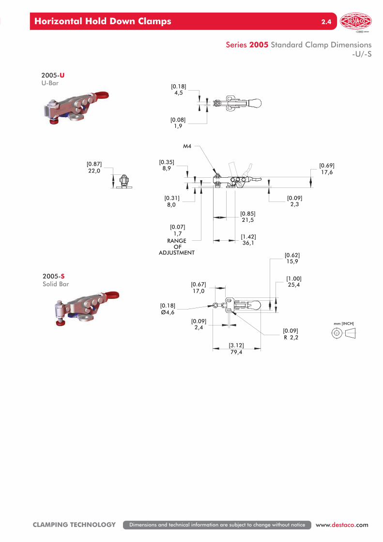
Series 2005 Standard Clamp Dimensions-U/-S
2005-SSolid Bar
2005-UU-Bar
mm [INCH]
UK 2 2010 Horizontal Clamping_Layout 1 07.09.12 13:29 Seite 4
Horizontal Hold Down Clamps
www.destaco.com CLAMPING TECHNOLOGYDimensions and technical information are subject to change without notice
2.5
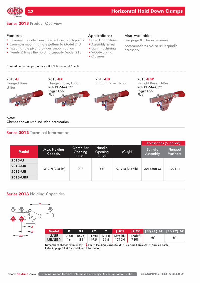
Series 2013 Product Overview
Series 2013 Technical Information
Series 2013 Holding Capacities
2013-URFlanged Base, U-Barwith DE-STA-CO®
Toggle Lock Plus
2013-UFlanged BaseU-Bar
2013-UBRStraight Base, U-Barwith DE-STA-CO®
Toggle Lock Plus
2013-UBStraight Base, U-Bar
Note:Clamps shown with included accessories.
Covered under one year or more U.S./International Patents
Features:• Increased handle clearance reduces pinch points• Common mounting hole pattern to Model 213• Fixed handle pivot provides smooth action• Nearly 2 times the holding capacity Model 213
Applications:• Checking fixtures• Assembly & test• Light machining• Woodworking• Closures
Also Available:See page 8.1 for accessories
Accommodates M5 or #10 spindle accessory
X
X2
Y
EF EF AF
HC HC
X1
2 1
Accessories (Supplied)
Model Max. HoldingCapacity
Clamp BarOpening
(+10°)
Handle Opening
(+10°)Weight
SpindleAssembly
FlangedWashers
2013-U
1310 N [295 lbf] 71° 58° 0,17kg [0.37lb] 2013208-M 1021112013-UR
2013-UB
2013-UBR
Model X X1 X2 Y ‡HC1 ‡HC2 ‡EF(X1):AF ‡EF(X2):AFU/UR
UB/UBR[0.63]
16[0.95]
24[1.95]49,5
[2.34]59,5
[295lbf.]1310N
[175lbf.]780N
6:1 4:1
Dimensions shown “mm [inch]” ‡ HC = Holding Capacity, EF = Exerting Force, AF = Applied ForceRefer to page 19.4 for additional information.
UK 2 2010 Horizontal Clamping_Layout 1 07.09.12 13:29 Seite 5

Horizontal Hold Down Clamps
www.destaco.comCLAMPING TECHNOLOGY Dimensions and technical information are subject to change without notice
2. 6
Series 2013 Standard Clamp Dimensions-U/-UR/-UB/-UBR
2013-UFlanged BaseU-Bar
2013-UBRStraight Base, U-Barwith DE-STA-CO®
Toggle Lock Plus
mm [INCH]
50,7[1.99]
2,7[0.11]
4,1[0.16]
M5 OR #10-32
42,0
31,4
[1.65]
ADJUSTMENT
[2.65]
[1.30]
67,4
[1.23]
[0.30]7,5
RANGE OF
33,1
51,2[2.02]
[0.03]0,813,5
[0.53]
2,6[0.10]
[0.21]5,3
67,4[2.65]
25,4
149,2
[0.53]
[1.06]
6,1
[1.00]
17,7
13,5
42,0
[0.24]
26,9
[5.87]
[0.70][1.65]
0,8[0.03]
DE-STA-CO®
TOGGLE LOCKPLUS OPTION
UK 2 2010 Horizontal Clamping_Layout 1 07.09.12 13:29 Seite 6

Horizontal Hold Down Clamps
www.destaco.com CLAMPING TECHNOLOGYDimensions and technical information are subject to change without notice
2.7
Series 2017 Product Overview
Series 2017 Technical Information
Series 2017 Holding Capacities
2017-URFlanged Base, U-Barwith DE-STA-CO®
Toggle Lock Plus
2017-UFlanged BaseU-Bar
2017-UBRStraight Base, U-Barwith DE-STA-CO®
Toggle Lock Plus
2017-UBStraight BaseU-Bar
Note:Clamps shown with included accessories.
Covered under one year or more U.S./International Patents
Features:• Increased handle clearance reduces pinch points• Common mounting hole pattern to Model 217• Fixed handle pivot provides smooth action• Over 2½ times the holding capacity Model 217
Applications:• Checking fixtures• Assembly & test• Light machining• Woodworking• Closures
Also Available:See page 8.1 for accessories
Accommodates M6 or ¼" spindle accessory
X
X2
Y
EF EF AF
HC HC
X1
2 1
Accessories (Supplied)
Model Max. HoldingCapacity
Clamp BarOpening
(+10°)
Handle Opening
(+10°)Weight
SpindleAssembly
FlangedWashers
2017-U
2500 N [560 lbf] 73° 69° 0,44kg [0.97lb] 215208-M 2151052017-UR
2017-UB
2017-UBR
Model X X1 X2 Y ‡HC1 ‡HC2 ‡EF(X1):AF ‡EF(X2):AFU/UR
UB/UBR[1.08]27,4
[1.65]42
[3.15]80
[2.54]64,5
[560lbf.]2500N
[245lbf.]1090N
5:1 2.5:1
Dimensions shown “mm [inch]” ‡ HC = Holding Capacity, EF = Exerting Force, AF = Applied ForceRefer to page 19.4 for additional information.
UK 2 2010 Horizontal Clamping_Layout 1 07.09.12 13:29 Seite 7

Horizontal Hold Down Clamps
www.destaco.comCLAMPING TECHNOLOGY Dimensions and technical information are subject to change without notice
2. 8
Series 2017 Standard Clamp Dimensions-U/-UR/-UB/-UBR
2017-UFlanged BaseU-Bar
2017-UBRStraight Base, U-Barwith DE-STA-CO®
Toggle Lock Plus
5,0RANGE OF
ADJUSTMENT
[0.20]
2,8
8,2[0.32]
[0.11]
[1.68]42,6
[1.86]47,2
[1.03]26,2
30,8[1.21]
[8.65]219,7
M6 OR 1/4-20
51,6
106,8[4.21]
[0.98]24,8
[2.03]
[2.53]64,2
3,0[0.12]
R3,4[0.14]
[0.12]
[0.24]6,1
3,0
55,9[2.20]
76,1[3.00]49,4
[1.95]
5,1[0.20]
3,0[0.12]
mm [INCH]
DE-STA-CO®
TOGGLE LOCKPLUS OPTION
UK 2 2010 Horizontal Clamping_Layout 1 07.09.12 13:29 Seite 8

Horizontal Hold Down Clamps
www.destaco.com CLAMPING TECHNOLOGYDimensions and technical information are subject to change without notice
2.9
Series 2027 Product Overview
Series 2027 Technical Information
Series 2027 Holding Capacities
2027-URFlanged Base, U-Barwith DE-STA-CO®
Toggle Lock Plus
2027-UFlanged BaseU-Bar
2027-UBRStraight Base, U-Barwith DE-STA-CO®
Toggle Lock Plus
2027-UBStraight BaseU-Bar
Note:Clamps shown with included accessories.
Covered under one year or more U.S./International Patents
Features:• Increased handle clearance reduces pinch points• Common mounting hole pattern to Model 227• Fixed handle pivot provides smooth action• Over 1½ times the holding capacity Model 227
Applications:• Checking fixtures• Assembly & test• Light machining• Woodworking• Closures
Also Available:See page 8.1 for accessories
Accommodates M8 or 5/16" spindle accessory
X
X2
Y
EF EF AF
HC HC
X1
2 1
Accessories (Supplied)
Model Max. HoldingCapacity
Clamp BarOpening
(+10°)
Handle Opening
(+10°)Weight
SpindleAssembly
FlangedWashers
2027-U
3740 N [840 lbf] 68° 70° 0,61kg [1.34lb] 2007208-M 5071072027-UR
2027-UB
2027-UBR
Model X X1 X2 Y ‡HC1 ‡HC2 ‡EF(X1):AF ‡EF(X2):AFU/UR
UB/UBR[1.02]25,8
[1.75]44,5
[3.30]83,8
[2.54]64,5
[840lbf.]3740N
[480lbf.]2140N
5:1 3:1
Dimensions shown “mm [inch]” ‡ HC = Holding Capacity, EF = Exerting Force, AF = Applied ForceRefer to page 19.4 for additional information.
UK 2 2010 Horizontal Clamping_Layout 1 07.09.12 13:29 Seite 9

7,0RANGE OF
ADJUSTMENT
[0.28]
M8 OR 5/16-18
59,3 [2.86]72,7
112,3
[2.34]
[4.42]
[0.16]4,2
[1.32]33,6
19,1[0.75]
57,2[2.25]
90,6[3.57]
4,2[0.16]
6,1[0.24]
30,8
[2.86]
250,9
72,8
[9.88]
[1.21]
[1.03]26,2
[1.56]39,6
[1.81]
R
45,9
[0.14]3,4
2,8[0.11]
[0.33]
3,0[0.12]
8,3
56,4[2.22]
Horizontal Hold Down Clamps
www.destaco.comCLAMPING TECHNOLOGY Dimensions and technical information are subject to change without notice
2. 10
Series 2027 Standard Clamp Dimensions-U/-UR/-UB/-UBR
2027-UFlanged BaseU-Bar
2027-UBRStraight Base, U-Barwith DE-STA-CO®
Toggle Lock Plus
mm [INCH]
DE-STA-CO®
TOGGLE LOCKPLUS OPTION
UK 2 2010 Horizontal Clamping_Layout 1 07.09.12 13:30 Seite 10

Horizontal Hold Down Clamps
www.destaco.com CLAMPING TECHNOLOGYDimensions and technical information are subject to change without notice
2.11
Series 2037 Product Overview
Series 2037 Technical Information
Series 2037 Holding Capacities
2037-URFlanged Base, U-Barwith DE-STA-CO®
Toggle Lock Plus
2037-UFlanged BaseU-Bar
2037-UBRStraight Base, U-Barwith DE-STA-CO®
Toggle Lock Plus
2037-UBStraight BaseU-Bar
Note:Clamps shown with included accessories.
Covered under one year or more U.S./International Patents
Features:• Increased handle clearance reduces pinch points• Common mounting hole pattern to Model 237• Fixed handle pivot provides smooth action• Over 2½ times the holding capacity Model 237
Applications:• Checking fixtures• Assembly & test• Light machining• Woodworking• Closures
Also Available:See page 8.1 for accessories
Accommodates M10 or 3/8" spindle accessory
X
X2
Y
EF EF AF
HC HC
X1
2 1
Accessories (Supplied)
Model Max. HoldingCapacity
Clamp BarOpening
(+10°)
Handle Opening
(+10°)Weight
SpindleAssembly
FlangedWashers
2037-U
7470 N [1680 lbf] 73° 72° 1,34kg [2.95lb] 240208-M 2351062037-UR
2037-UB
2037-UBR
Model X X1 X2 Y ‡HC1 ‡HC2 ‡EF(X1):AF ‡EF(X2):AFU/UR
UB/UBR[1.39]35,3
[2.20]56
[5.05]128,3
[3.81]97
[1680lbf.]7470N
[700lbf.]3120N
5:1 3:1
Dimensions shown “mm [inch]” ‡ HC = Holding Capacity, EF = Exerting Force, AF = Applied ForceRefer to page 19.4 for additional information.
UK 2 2010 Horizontal Clamping_Layout 1 07.09.12 13:30 Seite 11

9,0RANGE OF
ADJUSTMENT
[0.35]
M10 OR 3/8-16
69,7
[4.41]
[3.05]
112
41,2
173,6
77,4
[1.00]
[6.83]
25,4
[2.75]
[1.62]
4,2[0.16]
2,0[0.08]
R4,3[0.17]
69,9[2.75]
106,1[4.18]
8,2[0.32] 4,2
[0.16]
[0.42]
[0.19]
[6.83]173,6
4,9
10,6
77,1[3.04]
61,7
10,2[0.40]
[1.63]41,3111,9
[4.40]
[13.36]339,3
R4,3[0.17]
[1.69]42,9
[2.50]63,4
[2.43]
2,0[0.08]
Horizontal Hold Down Clamps
www.destaco.comCLAMPING TECHNOLOGY Dimensions and technical information are subject to change without notice
2. 12
Series 2037 Standard Clamp Dimensions-U/-UR/-UB/-UBR
2037-UFlanged BaseU-Bar
mm [INCH]
DE-STA-CO®
TOGGLE LOCKPLUS OPTION
2037-UBRStraight Base, U-Barwith DE-STA-CO®
Toggle Lock Plus
UK 2 2010 Horizontal Clamping_Layout 1 07.09.12 13:30 Seite 12

Horizontal Hold Down Clamps
www.destaco.com CLAMPING TECHNOLOGYDimensions and technical information are subject to change without notice
2.13
Series 213 Technical Information
Series 213 Product Overview
Series 213 Holding Capacities
213-USSFlanged BaseU-Bar, StainlessSteel
213-UFlanged BaseU-Bar
213-UB-LStraight BaseOpen Bar
213-U-LFlanged BaseOpen Bar
213-UBStraight BaseU-Bar
Note:Clamps shown with included accessories.
Features:• Low profile• Large handle clearance in the open position• Available in stainless steel
Applications:• Assembly• Checking fixtures• Closures• Woodworking
Also Available:See page 8.1 for accessories
Accommodates M5 or #10 spindle accessory
Accessories (Supplied)
Model Max. HoldingCapacity
Clamp BarOpening
(+10°)
Handle Opening
(+10°)Weight
SpindleAssembly
FlangedWashers
213-U
670 N [150 lbf] 90° 60° 0,08kg [0.17lb]
213208-M 102111
213-USS 201943 102911
213-UB 213208-M 102111
213-U-L-- --
213-UB-L
This item is available upon request
X
X2
Y
EF EF AF
HC HC
X1
2 1
Model X X1 X2 Y ‡HC1 ‡HC2 ‡EF(X1):AF ‡EF(X2):AFU/USS/UBU-L/UB-L
[0.36]9,3
[0.75]19
[1.63]41,4
[1.81]46
[150lbf.]670N
[70lbf.]310N
7:1 3:1
Dimensions shown “mm [inch]” ‡ HC = Holding Capacity, EF = Exerting Force, AF = Applied ForceRefer to page 19.4 for additional information.
UK 2 2010 Horizontal Clamping_Layout 1 07.09.12 13:30 Seite 13

213-U†
Flanged BaseU-Bar
Horizontal Hold Down Clamps
www.destaco.comCLAMPING TECHNOLOGY Dimensions and technical information are subject to change without notice
2. 14
Series 213 Standard Clamp Dimensions-U/-USS/-UB
27,0[1.06]
19,0
[0.06]
[0.75][0.53]13,5
102,9[4.05]
[0.23]
25,4[1.00]
1,55,9 R2,2[0.08]
43,8[1.72]35,3
[1.39]
4,0[0.16]
[0.85]21,5
9,8[0.39]
5,4[0.21]
M5 OR #10IF SUPPLIED
[0.08]
[0.74]
[0.26]
[0.92][1.42]36,0
61,4[2.42]
2,0
18,8
ADJUSTMENT
23,3
6,6RANGE OF
9,5[0.37]
OPENING
213-UB
Series 213 Open Bar
31,2[1.23]
[0.21]5,4
21,5[0.85]
Flanged BaseModel
213-U-L
See page 2.14 for dimensions not shownStraight Base
Model213-UB-L
See page 8.7 for Complete offering of Open bar accessories
mm [INCH]
UK 2 2010 Horizontal Clamping_Layout 1 07.09.12 13:30 Seite 14

Horizontal Hold Down Clamps
www.destaco.com CLAMPING TECHNOLOGYDimensions and technical information are subject to change without notice
2.15
Series 217 Technical Information
Series 217 Product Overview
217-USSFlanged BaseU-Bar, StainlessSteel
217-UFlanged BaseU-Bar
217-UB-LStraight BaseOpen Bar
217-U-LFlanged BaseOpen Bar
217-UBStraight BaseU-Bar
Note:Clamps shown with included accessories.
Features:• Low profile• Large handle clearance in the open position• Available in stainless steel
Applications:• Assembly• Checking fixtures• Closures• Woodworking
Also Available:See page 8.1 for accessories
Accommodates M6 or ¼" spindle accessory
Accessories (Supplied)
Model Max. HoldingCapacity
Clamp BarOpening
(+10°)
Handle Opening
(+10°)Weight
SpindleAssembly
FlangedWashers
217-U 900 N [200 lbf]
91° 61° 0,18kg [0.40lb]
202208-M 215105
217-USS 1110 N [250 lbf] 202943 215105
217-UB
900 N [200 lbf]
202208-M 215105
217-U-L-- --
217-UB-L
This item is available upon request
UK 2 2010 Horizontal Clamping_Layout 1 07.09.12 13:30 Seite 15

3,0RANGE OF
ADJUSTMENT
[0.12]
49,6[1.95]
62,8[2.47]
5,0[0.20]
[0.19]
28,4
13,1
5,4
[6.58]
[0.52]
167,2
26,2
39,4
37,0
[1.12][1.55]
[0.21]
[1.03]
[1.46]
Ø 4,8
5,5[0.22] 3,0
[0.12]
M6 OR 1/4IF SUPPLIED
[1.23]31,1
58,4
12,5
[2.30][0.92]
[3.76]
23,4
[0.49]
95,4
2,5[0.10]
OPENING
217-UB
14,2[0.56]
39,0[1.54]
6,4[0.25]217-U†
Flanged BaseU-Bar
Horizontal Hold Down Clamps
www.destaco.comCLAMPING TECHNOLOGY Dimensions and technical information are subject to change without notice
2. 16
Series 217 Holding Capacities
X
X2
Y
EF EF AF
HC HC
X1
2 1
Model X X1 X2 Y ‡HC1 ‡HC2 ‡EF(X1):AF ‡EF(X2):AF
U
[0.53]13,5
[1.13]28,6
[2.63]66,8
[2.93]74,5
[200lbf.]900N
[80lbf.]360N
7:1 3:1USS [250lbf.]1110N
[100lbf.]440N
UB/U-L/UB-L
[200lbf.]900N
[80lbf.]360N
Dimensions shown “mm [inch]” ‡ HC = Holding Capacity, EF = Exerting Force, AF = Applied ForceRefer to page 19.4 for additional information.
Series 217 Standard Clamp Dimensions-U/-USS/-UB
Series 217 Open Bar
53,2[2.09]
[0.25]6,4
38[1.49]
Flanged BaseModel
217-U-L
Straight BaseModel
217-UB-L
mm [INCH]
See page 2.16 for dimensions not shown
See page 8.7 for Complete offering of Open bar accessories
UK 2 2010 Horizontal Clamping_Layout 1 07.09.12 13:30 Seite 16

Horizontal Hold Down Clamps
www.destaco.com CLAMPING TECHNOLOGYDimensions and technical information are subject to change without notice
2.17
Series 227 Technical Information
Series 227 Product Overview
227-USSFlanged BaseU-Bar, StainlessSteel
227-UFlanged BaseU-Bar
227-UB-LStraight BaseOpen Bar
227-U-LFlanged BaseOpen Bar
227-UBStraight BaseU-Bar
Note:Clamps shown with included accessories.
Features:• Low profile• Large handle clearance in the open position.• Available in stainless steel
Applications:• Assembly• Checking fixtures• Closures• Woodworking
Also Available:See page 8.1 for accessories
Accommodates M6 or 5/16" spindle accessory
Accessories (Supplied)
Model Max. HoldingCapacity
Clamp BarOpening
(+10°)
Handle Opening
(+10°)Weight
SpindleAssembly
FlangedWashers
227-U 2220 N [500 lbf]
91° 56° 0,31kg [0.68lb]
225208-M 507107
227-USS 2670 N [600 lbf] 207943 507907
227-UB
2220 N [500 lbf]
225208-M 507107
227-U-L-- --
227-UB-L
This item is available upon request
UK 2 2010 Horizontal Clamping_Layout 1 07.09.12 13:30 Seite 17

OPENING
[0.56]14,3
4,0RANGE OF
ADJUSTMENT
[0.16]
[0.19]Ø 4,8
75,3[2.96]
61,1[2.40]
6,0[0.24]
31,8
[4.23]
[1.25]
[2.65]67,2
39,3[1.55]
107,3
3,0[0.12]
M8 OR 5/16IF SUPPLIED
[0.83]21,2
[1.54]39,1
8,4[0.33]
26,0
6,6
[1.02]
2,5[0.10]
189,9[7.48]
[0.28]
[1.74]44,2
40,0
[1.24]
[1.57]
[0.26]
7,0
31,6
6,6[0.26]
227-U†
Flanged BaseU-Bar
Horizontal Hold Down Clamps
www.destaco.comCLAMPING TECHNOLOGY Dimensions and technical information are subject to change without notice
2. 18
Series 227 Holding Capacities
X
X2
Y
EF EF AF
HC HC
X1
2 1
mm [INCH]
Model X X1 X2 Y ‡HC1 ‡HC2 ‡EF(X1):AF ‡EF(X2):AF
U
[0.39]10,0
[1.25]31,8
[2.75]70,0
[3.58]91,0
[500lbf.]2220N
[225lbf.]1000N
8:1 3:1USS [600lbf.]2670N
[270lbf.]1200N
UB/U-L/UB-L
500lbf.]2220N
[225lbf.]1000N
Dimensions shown “mm [inch]” ‡ HC = Holding Capacity, EF = Exerting Force, AF = Applied ForceRefer to page 19.4 for additional information.
Series 227 Standard Clamp Dimensions-U/-USS/-UB
Series 227 Open Bar
60,7[2.39]
112,5[4.43]
[0.34]8,6
37,7[1.49]
212,8[8.38]
Flanged BaseModel
227-U-L
Straight BaseModel
227-UB-L
See page 2.18 for dimensions not shown
See page 8.7 for Complete offering of Open bar accessories
UK 2 2010 Horizontal Clamping_Layout 1 07.09.12 13:30 Seite 18

Horizontal Hold Down Clamps
www.destaco.com CLAMPING TECHNOLOGYDimensions and technical information are subject to change without notice
2.19
Series 237 Technical Information
Series 237 Product Overview
Series 237 Holding Capacities
237-USSFlanged BaseU-Bar, StainlessSteel
237-UFlanged BaseU-Bar
Note:Clamps shown with included accessories.
Features:• Low profile• Large handle clearance in the open position.• Available in stainless steel
Applications:• Assembly• Checking fixtures• Welding
Also Available:See page 8.1 for accessories
Accommodates M10 or 3/8" spindle accessory
Accessories (Supplied)
Model Max. HoldingCapacity
Clamp BarOpening
(+10°)
Handle Opening
(+10°)Weight
SpindleAssembly
FlangedWashers
237-U 3340 N [750 lbf]93° 59° 0,73kg [1.60lb]
240208-M 235106
237-USS 3780 N [850 lbf] 237943 235906
This item is available upon request
X
X2
Y
EF EF AF
HC HC
X1
2 1
Model X X1 X2 Y ‡HC1 ‡HC2 ‡EF(X1):AF ‡EF(X2):AF
U[0.81]20,6
[1.75]44,5
[4.50]114,3
[5.25]133,3
[750lbf.]3340N
[290lbf.]1290N
6:1 2:1USS [850lbf.]
3780N[330lbf.]1470N
Dimensions shown “mm [inch]” ‡ HC = Holding Capacity, EF = Exerting Force, AF = Applied ForceRefer to page 19.4 for additional information.
UK 2 2010 Horizontal Clamping_Layout 1 07.09.12 13:30 Seite 19

237-U†
Flanged BaseU-Bar
Horizontal Hold Down Clamps
www.destaco.comCLAMPING TECHNOLOGY Dimensions and technical information are subject to change without notice
2. 20
Series 237 Standard Clamp Dimensions-U/-USS
11,0RANGE OF
ADJUSTMENT
[0.43]
80,8[3.18]
M10 OR 3/8IF SUPPLIED
[3.98]
19,0[0.75]
101,1
42,3[1.67]
158,1[6.23]
4,0[0.16]
OPENING
[0.31]8,8
[0.35]
57,0[2.24]
20,5
8,0
[1.61]41,0
[1.69]43,0
101,1
Ø 5,8[0.23]
[2.28]58,0
[3.98]
[0.81]
2,0[0.08]
70,0[2.76]
24,6[0.97]
10,6[0.42]
280,0[11.02]
mm [INCH]
UK 2 2010 Horizontal Clamping_Layout 1 07.09.12 13:30 Seite 20

Horizontal Hold Down Clamps
www.destaco.com CLAMPING TECHNOLOGYDimensions and technical information are subject to change without notice
2.21
Series 245 Technical Information
Series 245 Product Overview
Series 245 Holding Capacities
245-UFlanged BaseU-Bar
Note:Clamps shown with included accessories.
Features:• Low profile• Large handle clearance in the open position.
Applications:• Assembly• Checking fixtures• Welding
Also Available:See page 8.1 for accessories
Accommodates M12 or 1/2"spindle accessory
Accessories (Supplied)
Model Max. HoldingCapacity
Clamp BarOpening
(+10°)
Handle Opening
(+10°)Weight
SpindleAssembly
FlangedWashers
245-U 4450 N [1000 lbf] 105° 74° 1,32kg [2.90lb] 247208-M 247109
X
X2
Y
EF EF AF
HC HC
X1
2 1
Model X X1 X2 Y ‡HC1 ‡HC2 ‡EF(X1):AF ‡EF(X2):AF
U [0.50]12,7
[2.00]50,8
[5.00]127
[6.09]154,7
[1000lbf.]4450N
[400lbf.]1780N
11:1 5:1
Dimensions shown “mm [inch]” ‡ HC = Holding Capacity, EF = Exerting Force, AF = Applied ForceRefer to page 19.4 for additional information.
UK 2 2010 Horizontal Clamping_Layout 1 07.09.12 13:30 Seite 21

245-UFlanged BaseU-Bar
Horizontal Hold Down Clamps
www.destaco.comCLAMPING TECHNOLOGY Dimensions and technical information are subject to change without notice
2. 22
Series 245 Standard Clamp Dimensions
mm [INCH]
8,0RANGE OF
ADJUSTMENT
[0.31]
41,3
41,2
[0.50]
[1.62]
12,7 Ø 8,7[0.34]
[12.23]310,6
[2.62]66,6
[2.63]66,7
[1.63]
123,6[4.87]
M12 OR 1/4IF SUPPLIED
123,6[7.49]
55,5
[4.87]
25,4
190,3
[2.19]
[1.00]
4,7[0.19]
OPENING
107,8[4.24]
[1.37]34,7
[3.20]81,3
13,5[0.53]
UK 2 2010 Horizontal Clamping_Layout 1 07.09.12 13:30 Seite 22

Series 205 Technical Information
Series 205 Product Overview
Horizontal Hold Down Clamps
www.destaco.com CLAMPING TECHNOLOGYDimensions and technical information are subject to change without notice
2.23
Accessories (Supplied)
Model Max. HoldingCapacity
Clamp BarOpening
(+10°)
Handle Opening
(+10°)Weight
SpindleAssembly
FlangedWashers
205-U
270N [60 lbf]90° 80°
0,03kg [0.06lb]
205208-M 105106205-UB
205-UL
205-UR
205-USS 340N [75 lbf] 205943 105906
205-S
270N [60 lbf]94° 82°
205208-M--
205-SB
205-SL
205-SR
205-SSS 340N [75 lbf] 205943
This item is available upon request
205-UB
Straight BaseU-Bar
205-UFlanged BaseU-Bar
205-USSFlanged BaseU-Bar, Stainless Steel
205-URRight FlangedBase, U-Bar
205-SRRight FlangedBase, Solid Bar
205-SLLeft Flanged Base,Solid Bar
205-SFlanged BaseSolid Bar
205-SBStraight BaseSolid Bar
205-SSSFlanged BaseSolid Bar, Stainless Steel
205-ULLeft FlangedBase, U-Bar
Note:Clamps shown with included accessories.
Features:• Smallest of the Horizontal Hold Down clamps• Ideal for light duty clamping in tight spaces• Stainless steel models furnished without
plastic grip
Applications:• Assembly• Closures• Woodworking• Light duty
clamping
Also Available:See page 8.1 for accessories
Accommodates M4 or #8 spindle accessory
UK 2 2010 Horizontal Clamping_Layout 1 07.09.12 13:31 Seite 23

Horizontal Hold Down Clamps
X
X2
Y
EF EF AF
HC HC
X1
2 1
Series 205 Holding Capacities
Series 205 Standard Clamp Dimensions-U/-UB/-UL-/-UR/-USS/-S/-SB/-SL/-SR/-SSS
1,5RANGE OF
ADJUSTMENT
[0.06]
M4 OR #8IF SUPPLIED
[0.67]
6,3
17,17,5
18,6
[0.25]
[1.68]
[0.73]
42,6
[0.30]
1,5[0.06]
OPENING
[0.63]16,0
2,4[0.09]
4,0[0.16]
[0.18]
[0.37]9,5
68,8[2.71]
4,6
5,5[0.21]
72,5
15,8
24,1[0.95]
[0.62]
[0.09]
2,2[0.08]
[0.62]
[2.85] R
15,8
2,4
Ø 4,3[0.17]
[0.06]1,5
24,1[0.95]
3,0[0.12]
mm [INCH]
www.destaco.comCLAMPING TECHNOLOGY Dimensions and technical information are subject to change without notice
2. 24
205-U†
Flanged BaseU-Bar
205-S†
Flanged BaseSolid Bar
Model X X1 X2 Y ‡HC1 ‡HC2 ‡EF(X1):AF ‡EF(X2):AF
U
[0.22]5,6
[0.43]11
[0.81]20,5
[1.31]33,2
[60lbf.]270N
[50lbf.]220N
9:1 5:1USS [75lbf.]
340N[65lbf.]290N
S-- --
[60lbf.]270N
-- 4:1SSS [75lbf.]
340NDimensions shown “mm [inch]” ‡ HC = Holding Capacity, EF = Exerting Force, AF = Applied ForceRefer to page 19.4 for additional information.
UK 2 2010 Horizontal Clamping_Layout 1 07.09.12 13:31 Seite 24
Horizontal Hold Down Clamps
www.destaco.com CLAMPING TECHNOLOGYDimensions and technical information are subject to change without notice
2.25
Series 215 Technical Information
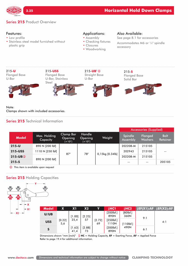
Series 215 Product Overview
Series 215 Holding Capacities
215-USSFlanged BaseU-Bar, StainlessSteel
215-UFlanged BaseU-Bar
215-SFlanged BaseSolid Bar
215-UB†
Straight BaseU-Bar
Note:Clamps shown with included accessories.
Features:• Low profile• Stainless steel model furnished without
plastic grip
Applications:• Assembly• Checking fixtures• Closures• Woodworking
Also Available:See page 8.1 for accessories
Accommodates M6 or ¼" spindle accessory
Accessories (Supplied)
Model Max. HoldingCapacity
Clamp BarOpening
(+10°)
Handle Opening
(+10°)Weight
SpindleAssembly
FlangedWashers
BoltRetainer
215-U 890 N [200 lbf]
87° 78° 0,15kg [0.34lb]
202208-M 215105
--215-USS 1110 N [250 lbf] 202943 215105
215-UB890 N [200 lbf]
202208-M 215105
215-S -- -- 205105
This item is available upon request
X
X2
Y
EF EF AF
HC HC
X1
2 1
Model X X1 X2 Y ‡HC1 ‡HC2 ‡EF(X1):AF ‡EF(X2):AF
U/UB
[0.22]5,6
[1.00]25,4
[2.25]57 [2.72]
69
[200lbf.]890N
[80lbf.]360N
9:14:1USS [250lbf.]
1110N [110lbf.]490N
S [1.63]41,4
[2.88]73
[200lbf.]890N
6:1
Dimensions shown “mm [inch]” ‡ HC = Holding Capacity, EF = Exerting Force, AF = Applied ForceRefer to page 19.4 for additional information.
UK 2 2010 Horizontal Clamping_Layout 1 07.09.12 13:31 Seite 25

215-U†
Flanged BaseU-Bar
215-SFlanged BaseSolid Bar
Horizontal Hold Down Clamps
www.destaco.comCLAMPING TECHNOLOGY Dimensions and technical information are subject to change without notice
2. 26
Series 215 Standard Clamp Dimensions-U/-USS/-UB/-S
6,6RANGE OF
ADJUSTMENT
[0.26]
[1.43]36,4
[5.46]138,6
[1.06]27,0
0,8
35,0[1.38]
[0.19] [0.87]22,0
[0.03]
6,0[0.24]
4,8
56,6[2.23] [0.20]
5,2Ø 7,2[0.28]
19,7[0.78]
[1.26]32,0
7,0[0.28]
5,0[0.20]
[1.41]
25,5
[0.10]
93,5
[2.25]
[1.00]
[3.68]
[1.53]
57,1
38,9
2,5
35,8
12,7[0.50]
OPENINGM6 OR 1/4IF SUPPLIED
215-UB
mm [INCH]
UK 2 2010 Horizontal Clamping_Layout 1 07.09.12 13:31 Seite 26

Horizontal Hold Down Clamps
www.destaco.com CLAMPING TECHNOLOGYDimensions and technical information are subject to change without notice
2.27
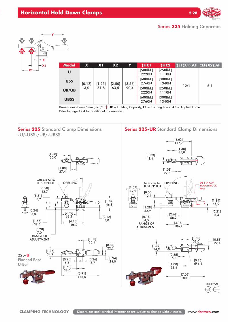
Series 225 Technical Information
Series 225 Product Overview
225-USSFlanged Base, U-Bar,Stainless Steel
225-UFlanged BaseU-Bar
225-UBSSStraight Base, U Bar,Stainless Steel
225-UBStraight BaseU Bar
225-URFlanged Base, U-Barwith DE-STA-CO®
Toggle Lock Plus
Note:Clamps shown with included accessories.
Covered under one year or more U.S./International Patents
Features:• Low profile• Stainless steel model furnished without
plastic grip• Available with DE-STA-CO® Toggle Lock Plus
Applications:• Assembly• Checking fixtures• Closures• Woodworking
Also Available:See page 8.1 for accessories
Accommodates M8 or 5/16" spindle accessory
Accessories (Supplied)
Model Max. HoldingCapacity
Clamp BarOpening
(+10°)
Handle Opening
(+10°)Weight
SpindleAssembly
FlangedWashers
225-U 2220 N [500 lbf]
92° 70°
0,25kg [0.55lb]225208-M 507107
225-USS 2760 N [600 lbf] 207943 507907
225-UR2220 N [500 lbf]
0,31kg [0.69lb]225208-M 507107
225-UB0,25kg [0.55lb]
225-UBSS 2760 N [600 lbf] 207943 507907
This item is available upon request
UK 2 2010 Horizontal Clamping_Layout 1 07.09.12 13:31 Seite 27
4,5RANGE OF
ADJUSTMENT
[0.18]
M8 or 5/16IF SUPPLIED
[1.29]
106,2
[0.21]
12,7
[2.69]
[0.50]
68,2
32,9
[4.18]
5,4
48,0[1.89]
OPENING
[1.38]35,0
[1.08]27,5
117,7[4.63]
8,4[0.33]
[7.09]180,0
25,4[1.00]
[1.50]38,0
34,9[1.37]
[0.88]
[0.26]Ø 6,6
22,4
6,3[0.25]
39,9[1.57]
Horizontal Hold Down Clamps
www.destaco.comCLAMPING TECHNOLOGY Dimensions and technical information are subject to change without notice
2. 28
Series 225 Holding Capacities
X
X2
Y
EF EF AF
HC HC
X1
2 1
7,0RANGE OF
ADJUSTMENT
[0.28]
M8 OR 5/16IF SUPPLIED
[1.84]
[0.50]12,7
46,8
[4.18]106,2
3,0[0.12]
[1.31]33,2
68,2[2.69]
39,6[1.56]
OPENING
[0.87]
6,3[0.25]
34,9[1.37]
[1.50]38,0
22,2
[1.00]25,4
[6.91]175,5
[0.26]6,7 24,0
[0.94]
6,0[0.24]
35,0[1.38]
27,4[1.08]
mm [INCH]
Model X X1 X2 Y ‡HC1 ‡HC2 ‡EF(X1):AF ‡EF(X2):AF
U
[0.12]3,0
[1.25]31,8
[2.50]63,5
[3.56]90,4
[500lbf.]2220N
[250lbf.]1110N
12:1 5:1USS [600lbf.]
2760N[300lbf.]1340N
UR/UB [500lbf.]2220N
[250lbf.]1110N
UBSS [600lbf.]2760N
[300lbf.]1340N
Dimensions shown “mm [inch]” ‡ HC = Holding Capacity, EF = Exerting Force, AF = Applied ForceRefer to page 19.4 for additional information.
Series 225 Standard Clamp Dimensions -U/-USS-/UB/-UBSS
Series 225-UR Standard Clamp Dimensions
DE-STA-CO®
TOGGLE LOCKPLUS
225-U†
Flanged BaseU-Bar
UK 2 2010 Horizontal Clamping_Layout 1 07.09.12 13:31 Seite 28

Horizontal Hold Down Clamps
www.destaco.com CLAMPING TECHNOLOGYDimensions and technical information are subject to change without notice
2.29
Series 235 Technical Information
Series 235 Product Overview
Series 235 Holding Capacities
235-USSFlanged Base, U-Bar,Stainless Steel
235-UFlanged BaseU-Bar
235-UBStraight BaseU-Bar
235-URFlanged Base, U-Barwith DE-STA-CO®
Toggle Lock Plus
Note:Clamps shown with included accessories.
Covered under one year or more U.S./International Patents
Features:• Low profile• Available with DE-STA-CO® Toggle Lock Plus• Available in stainless steel
Applications:• Assembly• Checking fixtures• Welding• Closures• Woodworking
Also Available:See page 8.1 for accessories
Accommodates M10 or 3/8" spindle accessory
Accessories (Supplied)
Model Max. HoldingCapacity
Clamp BarOpening
(+10°)
Handle Opening
(+10°)Weight
SpindleAssembly
FlangedWashers
235-U 3340 N [750 lbf]
92° 70°
0,67kg [1.47lb]240208-M 235106
235-USS 3780 N [850 lbf] 237943 235906
235-UR3340 N [750 lbf]
0,74kg [1.64lb]240208-M 235106
235-UB 0,67kg [1.47lb]
This item is available upon request
X
X2
Y
EF EF AF
HC HC
X1
2 1
Model X X1 X2 Y ‡HC1 ‡HC2 ‡EF(X1):AF ‡EF(X2):AF
U
[0.25]6,4
[1.75]44,5
[4.13]105
[5.75]146
[750lbf.]3340N
[300lbf.]1330N
9:1 5:1USS [850lbf.]3780N
[360lbf.]1600N
UR/UB [750lbf.]3340N
[300lbf.]1330N
Dimensions shown “mm [inch]” ‡ HC = Holding Capacity, EF = Exerting Force, AF = Applied ForceRefer to page 19.4 for additional information.
UK 2 2010 Horizontal Clamping_Layout 1 07.09.12 13:31 Seite 29

235-U†
Flanged BaseU-Bar
235-UR†
Flanged Base, U-Barwith DE-STA-CO®
Toggle Lock Plus
Horizontal Hold Down Clamps
www.destaco.comCLAMPING TECHNOLOGY Dimensions and technical information are subject to change without notice
2. 30
Series 235 Standard Clamp Dimensions-U/-USS-/UR-/UB
12,0RANGE OF
ADJUSTMENT
[0.47]
[1.63]41,3
57,2
[0.31]
[2.25]
[10.50]266,7
[1.63]41,3
[2.26]57,3
8,0Ø 8,4[0.33]
M10 OR 3/8IF SUPPLIED
[0.22]
162,8
[0.75]
[6.41]
43,3[1.70]
105,6[4.16]
19,0
5,5
64,9[2.56]
OPENING
[1.60]40,6
[2.32]59,0
11,1[0.44]
M10 OR 3/8IF SUPPLIED
8
Ø8,4[0.33]
[10.70]271,4
2.2657,3
[1.63]41,3
[2.25]57,2
[1.63]41,3
[0.31]
61[2.40]
40,7[1.60]
11,1[0.44]
8[0.31]
41,3[1.63]
Ø8,4[Ø 0.33]
19,1[0.75]
105,6[4.16]
53,2[2.09]
44,4[1.75] 57,2
[2.25]
92° 70°
11.3RANGE OF
ADJUSTMENT
[0.45]
mm [INCH]
DE-STA-CO®
TOGGLE LOCKPLUS
Series 235-URStandard Clamp Dimensions
UK 2 2010 Horizontal Clamping_Layout 1 07.09.12 13:31 Seite 30

Horizontal Hold Down Clamps
www.destaco.com CLAMPING TECHNOLOGYDimensions and technical information are subject to change without notice
2.31
Series 305, 307, 309 Technical Information
Series 305, 307, 309 Product Overview
Accessories (Supplied)
Model Max. HoldingCapacity
Clamp BarOpening
(+10°)
Handle Opening
(+10°)Weight
SpindleAssembly
FlangedWashers
305-U 670 N [150 lbf]
90° 170° 0,06kg [0.13lb]
305208-M 102111
305-USS 900 N [200 lbf] 201943 102911
305-UR 670 N [150 lbf] 305208-M 102111
307-U
1560 N [350 lbf] 92° 173° 0,24kg [0.54lb]
307208-M 507107
307-USS 207943 507907
307-UR 307208-M 507107
309-U
3340 N [750 lbf] 90° 168° 1,30kg [0.59lb]
309208 235106
309-USS 237943 235906
309-UR 309208 235106
This item is available upon request
305-USSFlanged BaseU-Bar, Stainless Steel
305-UFlanged BaseU-Bar
307-USSFlanged BaseU-Bar, Stainless Steel
307-UFlanged BaseU-Bar
309-URFlanged Base,U-Bar with DE-STA-CO®
Toggle Lock Plus
309-USSFlanged BaseU-Bar, Stainless Steel
307-URFlanged Base,U-Bar with DE-STA-CO®
ToggleLock Plus
309-UFlanged BaseU-Bar
305-URFlanged Base,U-Bar with DE-STA-CO®
Toggle Lock Plus
Note:Clamps shown with included accessories.
Features:• Compact design suitable for use in
confined spaces• Available with DE-STA-CO® Toggle Lock Plus• Stainless steel models available
Applications:• Assembly & Test• Light Machining• Closures• Woodworking
Also Available:See page 8.1 for accessories
UK 2 2010 Horizontal Clamping_Layout 1 07.09.12 13:32 Seite 31

305-U†
Flanged BaseU-Bar
307-UR†
Flanged Base,U-Bar with DE-STA-CO®
ToggleLock Plus
Horizontal Hold Down Clamps
www.destaco.comCLAMPING TECHNOLOGY Dimensions and technical information are subject to change without notice
2. 32
Y
X1X
X2
EF
HC
EF
HC2 1
AF
Series 305, 307, 309 Holding Capacities
Series 305, 307, 309 Standard Clamp Dimensions-U/-USS/-UR
mm [INCH]
Model X X1 X2 Y ‡HC1 ‡HC2 ‡EF(X1):AF ‡EF(X2):AF
305-U/UR[0.58]14,6
[1.38]35
[1.88]47,7
[1.14]29
[150lbf.]670N
[110lbf.]490N
3:12:1
305-USS [200lbf.]900N
[150lbf.]670N
307-U/UR/USS
[0.94]24
[1.88]47,7
[2.50]63,5
[1.77]45
[350lbf.]1560N
[260lbf.]1160N
309-U/UR/USS
[1.34]34
[2.50]63,5
[3.50]89
[2.70]68,5
[750lbf.]3340N
[530lbf.]2360N
4:1
Dimensions shown “mm [inch]” ‡ HC = Holding Capacity, EF = Exerting Force, AF = Applied ForceRefer to page 19.4 for additional information.
Model A A1 A3 B B1 C C1 C2 D F H L L1 L2 L3 M
305-U/UR [0.53]13,5
[1.035]26,3
[0.25]6,4
[0.63]16,0
[1.02]25,9
[0.48]12,2
[0.31]7,9
[0.08]2,0
[0.18]4,6
[0.21]5,3
[1.43]36,3
[2.21]56,1
[1.19]30,2
[0.51]13,0
[0.50]12,7
[#10]M5
307-U/UR [0.91]23,1
[1.72]43,7
[0.40]10,2
[1.14]29,0
[1.80]45,7
[0.89]22,6
[0.50]12,7
[0.12]3,0
[0.28]7,1
[0.33]8,4
[2.36]59,9
[3.61]91,7
[1.89]48,0
[0.86]21,8
[0.75]19,1
[5/16]M8
309-U/UR [1.38]35,1
[2.52]64,0
[0.58]14,7
[1.50]38,1
[2.47]62,7
[1.31]33,3
[0.75]19,1
[0.12]3,0
[0.33]8,4
[0.44]10,4
[3.53]89,7
[5.19]131,8
[2.68]68,1
[1.28]32,5
[1.06]26,9
[3/8-16]M10
ADJUSTMENT
"E"RANGE OF
"M"IF SUPPLIED
L
L1
C
C2
C1
OPENING
H
F
L3
L2
B1B
A
A1
A3Ø D
DE-STA-CO®
TOGGLE LOCKPLUS
UK 2 2010 Horizontal Clamping_Layout 1 07.09.12 13:32 Seite 32

Horizontal Hold Down Clamps
www.destaco.com CLAMPING TECHNOLOGYDimensions and technical information are subject to change without notice
2.33
Series 206 Product Overview
206-HSSFlanged BaseHigh U-Bar, Stainless Steel
206-SSFlanged BaseLow U-Bar, Stainless Steel
Features:• All stainless steel construction • Offers good bar clearance under clamping
bar while maintaining low profile
Applications:• Assembly• Chemical
processing• Closures• Light duty
clamping
Also Available:See page 8.1 for accessories
Accommodates M4 or #8 spindle accessory
Series 206 Technical Information
Accessories (Supplied)
Model Max. HoldingCapacity
Clamp BarOpening
(+10°)
Handle Opening
(+10°)Weight
SpindleAssembly
FlangedWashers
206-SS440 N [100 lbf] 90° 90° 0,03kg [0.07lb] 205943 105906
206-HSS
Model 206-HSS shown securing a platen on a prototyping machine.
UK 2 2010 Horizontal Clamping_Layout 1 07.09.12 13:32 Seite 33

Horizontal Hold Down Clamps
www.destaco.comCLAMPING TECHNOLOGY Dimensions and technical information are subject to change without notice
2. 34
Series 206 Holding Capacities
X
X2
Y
EF EF AF
HC HC
X1
2 1
Series 206 Standard Clamp Dimensions-SS/-HSS
mm [INCH]
Model X X1 X2 Y ‡HC1 ‡HC2 ‡EF(X1):AF ‡EF(X2):AF
SS/HSS [0.20]5
[0.43]11
[1.06]27
[1.14]29
[100lbf.]440N
[50lbf.]220N
5:1 3:1
Dimensions shown “mm [inch]” ‡ HC = Holding Capacity, EF = Exerting Force, AF = Applied ForceRefer to page 19.4 for additional information.
27,0
[0.95]
[0.05]
[1.06]
[0.44]
[1.89]
1,2
48,1
[0.31]
24,2
8,0
"SS"11,3
19,2"HSS"
[0.76]
OPENINGM4 OR #8 IF SUPPLIED
[0.22]8,8
[0.35]
5,5
11,5[0.45]
[0.94]
[0.09]
[0.63]15,9
69,7[2.74]
[0.63]
[0.94]23,9
2,4
15,923,8
4,0[0.16]
UK 2 2010 Horizontal Clamping_Layout 1 07.09.12 13:32 Seite 34

Horizontal Hold Down Clamps
www.destaco.com CLAMPING TECHNOLOGYDimensions and technical information are subject to change without notice
2.35
Series 5305, 5310 Technical Information
Series 5305, 5310 Product Overview
Features:• Solid clamping arm may be modified to
suit requirements• Hardened steel pivot pins and bushings
provide long life• Black oxide finish• DE-STA-CO® Toggle Lock Plus versions available
Applications:• Welding fixtures• Assembly fixtures• Light machining
5305-B/5310-BSoildBase
5305/5310Flanged Base
5305-R/5310-RFlanged Base withDE-STA-CO®
Toggle Lock Plus
5305-BR/5310-BRSolid Base withDE-STA-CO®
Toggle Lock Plus
Model Max. HoldingCapacity
Clamp BarOpening
(+10°)
Handle Opening
(+10°)Weight
5305
[600lbf.]2670N
90° 69°
[1.08lbs] 0,49kg
5305-B [0.82lbs] 0,37kg
5305-R [1.09lbs] 0,49kg
5305-BR [0.83lbs] 0,37kg
5310
[1300lbf.]5780N
90° 69°
[2.84lbs] 1,29kg
5310-B [2.24lbs] 1,02kg
5310-R [2.87lbs] 1,30kg
5310-BR [2.27lbs] 1,03kg
This item is available upon request
UK 2 2010 Horizontal Clamping_Layout 1 07.09.12 13:32 Seite 35

Horizontal Hold Down Clamps
www.destaco.comCLAMPING TECHNOLOGY Dimensions and technical information are subject to change without notice
2. 36
Series 5305, 5310 Standard Clamp Dimensions
B2 B1
B
H
C2
OPENINGANGLE
C1
C
A2 A3
A4 A5
HANDLEOPENING
A
A1
ØD
F
L
DE-STA-CO®
TOGGLE LOCKPLUS OPTION
THIRD ANGLEPROJECTION
mm [INCH]
Model A A1 A2 A3 A4 A5 B B1 B2 C C1 C2 D F H L
5305[2.50]63,5
[3.15]80,0
[2.12]53,8
[2.75]69,9
[4.63]117,6
[5.27]133,9
[0.79]20,1
[0.98]24,9
--[0.81]20,6
[0.51]13,0
[0.31]7,9
[0.35]8,9
[0.51]13,0
[1.51]38,4
[8.36]212,4
5305-R [1.84]46,7
5310[3.63]92,2
[4.63]117,6
[2.63]66,8
[3.63]92,2
[6.25]158,8
[7.25]184,2
[1.13]28,7
[1.50]38,1
--[1.00]25,4
[0.75]19,1
[0.31]7,9
[0.41]10,4
[0.79]20,1
[2.00]50,8
[11.13]282,6
5310-R [2.31]58,7
[11.02]279,8
Model A3 A4 B2 C C1 F H L
5305-B[2.75]69,9
[4.63]117,6
--[0.81]20,6
[0.51]13,0
[0.51]13,0
[1.51]38,4
[8.36]212,4
5305-BR [1.84]46,7
5310-B[3.63]92,2
[6.25]158,8
--[1.00]25,4
[0.75]19,1
[0.79]20,1
[2.00]50,8
[11.13]282,6
5310-BR [2.31]58,7
[11.02]279,8
This item is available upon request
UK 2 2010 Horizontal Clamping_Layout 1 07.09.12 13:32 Seite 36