2100-467 info instalacion paquete.pdf
TRANSCRIPT

Manual 2100-467G
Page 1 of 23
SINGLE PACKAGE
AIR CONDITIONERS
MODELS
PA13242-A PA13302-A
PA13362-A PA13362-B
PA13422-A PA13422-B
PA13422-C PA13482-A
PA13482-B PA13482-C
PA13602-A PA13602-B
PA13602-C
INSTALLATION INSTRUCTIONS
Manual : 2100-467G
Supersedes: 2100-467F
File: Volume II Tab 10
Date: 06-04-10
Bard Manufacturing Company, Inc.
Bryan, Ohio 43506
Since 1914 . . . Moving ahead just as planned.
© Copyright 2006
Manual 2100-467G
Page 2 of 23
CONTENTS
Getting Other Informations and Publications ........ 3
General InstructionsImportant ................................................................ 4Shipping Damage .................................................... 4General ................................................................ 4Field Installed Heater Packages (Optional) ............. 4
InstallationLocation ................................................................ 9Slab Mounting .......................................................... 9Typical Installations ......................................... 9 & 12Condensate Drain Trap ......................................... 12Air Filters .............................................................. 12Wiring – Main Power ............................................. 13Wiring – 24V Low Voltage Control Circuit ............. 13Transformer Taps ................................................... 13Thermostats ........................................................... 13
Start Up and OperationGeneral .............................................................. 15Topping Off System Charge................................... 15Safety Practices ..................................................... 15Start Up Notes ....................................................... 15Three Phase Scroll Compressor Start UpInformation ............................................................. 16Sequence of Operation .......................................... 16Indoor Blower Motor .............................................. 16Compressor Control Module .......................... 16 & 17Adjustments ........................................................... 17Low Ambient Control ............................................. 17
Service and TroubleshootingService Hints ......................................................... 18Pressure Service Ports .......................................... 18Refrigerant Charge ................................................ 18Fan Blade Settings ................................................ 18Pressure Tables ............................................. 19 & 20Suction and Discharge Tube Brazing .................... 21
Troubleshooting GE Blower Motors ................ 22-23
Figures
Figure 1 Unit Dimensions ...................................... 8Figure 2 Slab Mounting at Ground Level ............ 10
Figure 3 Airflow and Service Access
Clearances ............................................ 10
Figure 4 Elevated Mounting Platform ...................11
Figure 5 Condensate Drain Trap ......................... 12
Figure 6 Low Voltage Wiring ............................... 14
Figure 7 Low Ambient Control Wiring ................. 17
Figure 8 Fan Blade Setting ................................. 18
Figure 9 Brazing Diagram ................................... 21
Figure 10 Motor Connections ................................ 22
Figure 11 Wiring (Connections/Voltage) ............... 23
Tables
Table 1 Rated CFM & ESP .................................. 4
Table 2 Electrical Specifications .......................... 5
Table 3 Opt. Field Installed Heater Packages ..... 6
Table 4 Opt. Field Installed Elec. Heater ............. 7
Table 5 Filter Requirements & Sizes ................. 12
Table 6 Thermostat Wire Size ........................... 13
Table 7 Wall Thermostats .................................. 13
Table 8 Fan Blade Setting Dimensions.............. 18
Table 9 Indoor Blower Performance .................. 18
Table 10 Pressure Table ...................................... 19
Table 11 Pressure Table ...................................... 20
Manual 2100-467G
Page 3 of 23
Getting Other Information and Publications
These publications can help you install the air
conditioner or heat pump. You can usually find these at
your local library or purchase them directly from the
publisher. Be sure to consult current edition of each
standard.
National Electrical Code ...................... ANSI/NFPA 70
Standard for the Installation .............. ANSI/NFPA 90A
of Air Conditioning and Ventilating Systems
Standard for Warm Air ...................... ANSI/NFPA 90B
Heating and Air Conditioning Systems
Load Calculation for ............................ ACCA Manual J
Residential Winter and Summer Air Conditioning
Duct Design for Residential .............. ACCA Manual D
Winter and Summer Air Conditioning and Equipment
Selection
FOR MORE INFORMATION, CONTACTTHESE PUBLISHERS:
ACCA Air Conditioning Contractors of America
1712 New Hampshire Ave. N.W.
Washington, DC 20009
Telephone: (202) 483-9370
Fax: (202) 234-4721
ANSI American National Standards Institute
11 West Street, 13th Floor
New York, NY 10036
Telephone: (212) 642-4900
Fax: (212) 302-1286
ASHRAE American Society of Heating, Refrigerating,
and Air Conditioning Engineers, Inc.
1791 Tullie Circle, N.E.
Atlanta, GA 30329-2305
Telephone: (404) 636-8400
Fax: (404) 321-5478
NFPA National Fire Protection Association
Batterymarch Park
P.O. Box 9101
Quincy, MA 02269-9901
Telephone: (800) 344-3555
Fax: (617) 984-7057
Manual 2100-467G
Page 4 of 23
GENERAL INSTRUCTIONS
IMPORTANT
The equipment covered in this manual is to be installed
by trained, experienced service and installation
technicians. All duct work, supply and return ducts,
must be properly sized for the design airflow
requirement of the equipment. ACCA is an excellent
guide to proper sizing. All duct work or portions thereof
not in the conditioned space should be properly
insulated in order to both conserve energy and prevent
condensation or moisture damage.
SHIPPING DAMAGE
Upon receipt of equipment, the carton should be
checked for external signs of shipping damage. If
damage is found, the receiving party must contact the
last carrier immediately, preferably in writing,
requesting inspection by the carrier’s agent.
GENERAL
The refrigerant system is completely assembled and
charged. All internal wiring is complete.
The unit is designed for use with or without duct work.
Flanges are provided for attaching the supply and return
ducts.
These instructions explain the recommended method to
install the air cooled self-contained unit and the
electrical wiring connections to the unit.
These instructions and any instructions packaged with
any separate equipment required to make up the entire
system should be carefully read before beginning the
installation. Note particularly “Starting Procedure” and
any tags and/or labels attached to the equipment.
While these instructions are intended as a general
recommended guide, they do not supersede any national
and/or local codes in any way. Authorities having
jurisdiction should be consulted before the installation is
made.
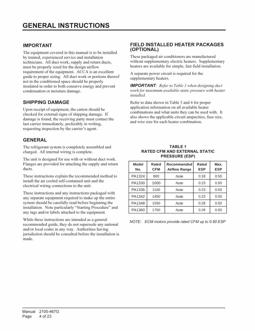
FIELD INSTALLED HEATER PACKAGES(OPTIONAL)
These packaged air conditioners are manufactured
without supplementary electric heaters. Supplementary
heaters are available for simple, fast field installation.
A separate power circuit is required for the
supplementary heaters.
IMPORTANT: Refer to Table 1 when designing duct
work for maximum available static pressure with heater
installed.
Refer to data shown in Table 3 and 4 for proper
application information on all available heater
combinations and what units they can be used with. It
also shows the applicable circuit ampacities, fuse size,
and wire size for each heater combination.
TABLE 1
RATED CFM AND EXTERNAL STATIC
PRESSURE (ESP)
NOTE: ECM motors provide rated CFM up to 0.50 ESP
ledoM.oN
detaRMFC
dednemmoceRegnaRwolfriA
detaRPSE
.xaMPSE
4231AP 008 etoN 81.0 05.0
0331AP 0001 etoN 32.0 05.0
6331AP 0011 etoN 32.0 05.0
2431AP 0541 etoN 32.0 05.0
8431AP 0551 etoN 82.0 05.0
0631AP 0571 etoN 82.0 05.0

Manual 2100-467G
Page 5 of 23
TA
BL
E 2
EL
EC
TR
ICA
L S
PE
CIF
ICA
TIO
NS
led
oM
A-24231A
PA-20331
AP
A-26331A
PB-26331
AP
A-22431A
PB-22431
AP
C-22431A
PA-28431
AP
B-28431A
PC-28431
AP
A-20631A
PB-20631
AP
C-20631A
P
–g
nitaR
cirtcelE
Ati
ucriC
–z
H06
1-06-802/0321-06-802/032
1-06-802/0323-06-802/032
1-06-802/0323-06-802/032
3-06-0641-06-802/032
3-06-802/0323-06-064
1-06-802/0323-06-802/032
3-06-064
egnaR
egatloV
gnitarepO
352-
791352
-791
352-
791352
-781
352-
791352
-781
605-414352
-791
352-
781605-414
352-
791352
-781
605-414
yticapm
AtiucriC
mumini
M51
8142
6133
3221
3392
4193
6271
CS
CB
911
5101
1251
822
418
6261
9
*ezi
Seri
Wdlei
F21
018
2101
0141
801
218
0101
eziS
eriW
dnuorG
2101
821
0101
418
0141
801
21
**.xa
M–
esuF
yaleD
0252
5302
0553
5105
0402
0604
52
802/032–
spm
AtinulatoT8.11/8.01
8.41/3.314.81/4.61
3.31/0.711.81/2.61
4.51/1.414.01
7.42/0.320.81/9.61
7.019.82/3.52
9.91/7.719.11
Ati
ucriC
–r
osserp
mo
C
epyTrosserp
moC
.piceR
.piceR
.piceR
.piceR
llorcS
llorcS
llorcS
llorcS
llorcS
llorcS
llorcS
llorcS
llorcS
stloV
802/032802/032
802/032802/032
802/032802/032
064802/032
802/032064
802/032802/032
064
spm
AdaoL
detaR
5.8/5.711/5.9
41/219.8/6.7
7.31/8.116.9/3.8
7.77.81/71
21/9.017.7
9.22/3.919.31/7.11
6.8
spm
Aroto
RkcoL
84/8475/75
47/4757/57
511/511511/511
05711/711
1.38/1.3805
431/431011/011
25
resne
dn
oC
dna
rot
oM
naF
MP
R/P
H–
rotoM
naF
528-
6/1528
-6/1
528-
6/1528
-6/1
528-
4/1528
-4/1
528-
4/1528
-4/1
528-
4/1528
-4/1
528-
4/1528
-4/1
528-
4/1
spm
Aroto
Mna
F1.1
1.11.1
1.15.1
5.15.1
5.15.1
5.15.1
5.15.1
MF
C/.aiD
–na
F0072/"42
0062/"420062/"42
0062/"420043/"42
0043/"420043/"42
0043/"420043/"42
0043/"420043/"42
0043/"420043/"42
rotar
opav
Ed
nar
oto
M
MP
R/P
H–
rotoM
rewol
BM
CE
-3/1
MC
E-
2/1M
CE
-2/1
MC
E-
2/1M
CE
-2/1
MC
E-
2/1M
CE
-2/1
MC
E-
4/3M
CE
-4/3
MC
E-
4/3M
CE
-4/3
MC
E-
4/3M
CE
-4/3
spm
A–
rotoM
rewol
B2.2
7.23.3
3.39.3
9.39.3
5.45.4
5.40.5
0.50.5
gnilooC
MF
C008
00010511
05110541
05410541
05510551
05510571
05710571
).zo014-
R(egrah
C57
58021
021061
061061
061061
061061
061061
)sdnuop(thgieW
gnippihS
063014
014014
044044
094044
044005
054054
005

Manual 2100-467G
Page 6 of 23
TA
BL
E 3
OP
TIO
NA
L F
IEL
D IN
ST
AL
LE
D H
EA
TE
R P
AC
KA
GE
S
ON
LY
TO
BE
US
ED
WIT
H T
HE
M
OD
EL
S I
ND
ICA
TE
D
egakca
Pretae
Hle
do
M&
stlo
Vesa
hP
A-24231A
PA-20331
AP
A-26331A
PB-26331
AP
A-22431A
PB-22431
AP
C-22431A
PA-28431
AP
B-28431A
PC-28431
AP
A-20631A
PB-20631
AP
C-20631A
P
50A-323
PH
E1-802/042
XX
X
01A-323
PH
E1-802/042
XX
X
51A-323
PH
E1-802/042
XX
90B-323
PH
E3-802/042
X
51B-323
PH
E3-802/042
X
50A-315
PH
E1-802/042
XX
X
01A-315
PH
E1-802/042
XX
X
51A-315
PH
E1-802/042
XX
X
90B-315
PH
E3-802/042
XX
X
51B-315
PH
E3-802/042
XX
X
90C-315
PH
E3-064
XX
X
51C-315
PH
E3-064
XX
X

Manual 2100-467G
Page 7 of 23
TA
BL
E 4
OP
TIO
NA
L F
IEL
D IN
ST
AL
LE
D E
LE
CT
RIC
HE
AT
ER
TA
BL
E
retaeH
egakca
P.
oNle
do
M
stlo
Vti
nU
sesah
P
yticapa
C&
WK.rt
Hstl
oV
042@
yticapa
C&
WK.rt
Hstl
oV
802@
V802/042.rt
Hs
pm
A
retaeH
lanret
nIti
ucriC
rekaerB
Bti
ucriC
WK
HU
TB
WK
HU
TB
dleiF.
oN
stiucri
C
3
.ni
Mti
ucriC
yticap
mA
1
revO.xa
Mt
nerru
Cn
oitcetor
P
2
dleiF
rew
oP
gniri
W
2
dn
uor
Gezi
Seri
W
50A-323
PH
E1-802/042
5001,71
57.3008,21
1.81/8.02
06/03
132/62
52/0301/01
01
01A-323
PH
E1-802/042
01001,43
05.7000,62
2.63/6.141
64/3505/06
8/601
51A-323
PH
E1-802/042
51002,15
52.11004,83
1.45/5.261
86/9707/08
4/48
50A-315
PH
E1-802/042
5001,71
57.3008,21
1.81/8.02
06/03
132/62
52/0301/01
01
01A-315
PH
E1-802/042
01001,43
05.7000,62
2.63/6.141
64/3505/06
8/601
51A-315
PH
E1-802/042
51002,15
52.11004,83
1.45/5.261
86/9707/08
4/48
90B-323
PH
E3-802/042
9007,03
57.6000,32
7.81/7.12eno
N1
42/8252/03
01/0101
51B-323
PH
E3-802/042
51002,15
52.11004,83
2.13/2.631
93/6404/05
8/801
90B-315
PH
E3-802/042
9007,03
57.6000,32
7.81/7.12eno
N1
42/8252/03
01/0101
51B-315
PH
E3-802/042
51002,15
52.11004,83
2.13/2.631
93/6404/05
8/801
90C-315
PH
E3-084
9007,03
8.01eno
N1
4151
4141
51C-315
PH
E3-084
51002,15
811
8203
0121
IMP
OR
TA
NT
:W
hile
th
is e
lectr
ica
l d
ata
is p
rese
nte
d a
s a
gu
ide
, it is im
po
rta
nt
to e
lectr
ica
lly c
on
ne
ct
pro
pe
rly s
ize
d f
use
s a
nd
co
nd
ucto
r w
ire
s in
acco
rda
nce
with
th
e N
atio
na
l E
lectr
ica
l C
od
e a
nd
all
exis
tin
g lo
ca
l co
de
s.
1M
axim
um
siz
e o
f th
e t
ime
de
lay f
use
or
HA
CR
cir
cu
it b
rea
ke
r fo
r p
rote
ctio
n o
f fie
ld w
irin
g d
evic
es.
2B
ase
d o
n w
ire
su
ita
ble
fo
r 7
5°C
. O
the
r w
irin
g m
ate
ria
ls m
ust
be
ra
ted
fo
r m
ark
ed
“M
inim
um
Cir
cu
it A
mpa
city”
or
gre
ate
r.
Ba
se
d o
n 7
5°C
co
pp
er
wir
e.
All w
irin
g m
ust
co
nfo
rm t
o t
he
Na
tio
na
l E
lectr
ic C
od
e a
nd
all lo
ca
l co
de
s.
3T
he
se
“M
inim
um
Cir
cu
it A
mpa
city”
va
lue
s a
re t
o b
e u
se
d f
or
siz
ing
th
e f
ield
po
we
r co
nd
ucto
rs.
Re
fer
to t
he
Na
tio
na
l E
lectr
ic C
od
e (
late
st
revis
ion
), A
rtic
le 3
10
fo
r p
ow
er
co
nd
ucto
r siz
ing
.

Manual 2100-467G
Page 8 of 23
FIGURE 1
DIMENSIONS OF UNITS
Return openingDrain access
Supply opening
High voltage knockout
Low voltage knockout
access door
Control panel door
Heater package access panel
Compressor
Heater package knockout
A
E
C
D
LW
B
F
Condenser air
Condenser airintake grille
intake grille
access doorBlower motor
Condenser fan
G47 11/16"
H
Unit Dimension Chart
MIS-2142 A
A C B C H (height) L (length) W (width) D E F G
PA/PH1324,1330,1336 5.875 32.875 13.875 32.875 26.25 53.25 38.125 23.25 1.125 1.375 35.625
PA/PH1342,1348,1360 9.875 37.875 15.875 37.875 33.25 55.25 42.375 30.25 1.5 2.375 38.125
UnitUnit General DimensionsSupply Size Return Size Unit Overall Dimensions

Manual 2100-467G
Page 9 of 23
INSTALLATION
LOCATION
GENERAL
The unit must be located outside, or in a well ventilated
area. It must not be in the space being heated or cooled.
A sound absorbing material should be considered if the
unit is to be installed in such a position or location that
might cause transmission of sound or vibration to the
living area or adjacent buildings.
SLAB MOUNTING
A minimum of 24 inches should be provided between
the coil inlet and any building surfaces. Provide a
minimum of three feet clearance on the service access
side of the unit. See Figure 2.
TYPICAL INSTALLATIONS
1. ROOF MOUNTED – The unit is mounted on a
sturdy base on the roof of the building. Return air to
the unit is brought through a single return grille
(grilles with built-in filters are best since they enable
easy access for filter changing). Return air ducts are
attached to the lower section of the front panel.
Supply air is brought from the unit to attic duct work
or to a furred down hall. Supply air duct is attached
to the top of the front panel.
CAUTION: All outdoor duct work must be
thoroughly insulated and weatherproofed. All
attic duct work must be thoroughly insulated.
Two inch thick insulation with suitable vapor
barrier is recommended for both outdoor and
attic runs.
In roof top installation, as in all installations, the air
conditioner must be level from side to side.
However, the unit should have a pitch along the
length to assure complete external drainage of
precipitation and of defrost condensate.
2. CRAWL SPACE – Duct work installed in crawl
space must be well insulated and provided with a
vapor barrier. In addition, the crawl space must be
thoroughly ventilated and provided with a good
vapor barrier as a ground cover. It is most desirable
to install the unit will be outdoors rather than inside
the crawl space, so that it will be readily accessible
for service.
3. SLAB MOUNTED AT GROUND LEVEL – This
type installation is ideal for homes with a slab floor
construction where a roof mounted unit is not
desired. The supply and return duct work can be run
through a furred closet space.
4. THROUGH THE WALL – This type installation
requires a suitable framework to be fabricated
capable of withstanding the unit weight. Normally
the unit will be insulated so as to minimize supply
and return duct work.

Manual 2100-467G
Page 10 of 23
36" min.
24" min.
24" min.
The distance between
1 inch clearance
Access
Air
Inle
tComp-
Nearest Structure
Air Inlet
Sup
ply
and
Ret
urn
Duc
ts
Nearest Structure
Nea
rest
Str
uctu
re
Bui
ldin
g
Control Panel
AccessControl Panel
Access
Heater PackageAccess
Blower Service
and
ressor
Blower Motor
Heater Package
Blower
Compressor
from top.
units only).
Condenser fanand motor access
above fan.Leave 60" min.
Side
View
View
Top
between duct andany combustible
material if distancebetween outside
wall and unit is lessthan 3 feet (needed
on electric heat
MIS-2143 A
Mounting Slab
Ground Level
Package Unit
Supply Duct
from building
Return Duct
requirements.
outside wall and unit
Air Outlet
varies with installation
1/4 inch per footslope away
Building
FIGURE 2
SLAB MOUNTING AT GROUND LEVEL
FIGURE 3
AIRFLOW AND SERVICE ACCESS CLEARANCES

Manual 2100-467G
Page 11 of 23
FIGURE 4
ELEVATED MOUNTING PLATFORM
Both legs must reston surface of platform
32°F or lower climate12" min. if in
48" min.
48" min.
32°F or lower climate12" min. if in
on surface of platformBoth legs must rest
Platform can be asshown or solid
Poured concrete,brick, or block
Metal frame
MIS-2144 A
* AS REQUIRED
*
*

Manual 2100-467G
Page 12 of 23
FIGURE 5
CONDENSATE DRAIN TRAP
5. OTHER INSTALLATIONS – Many other
installations are possible with the packaged air
conditioner. No matter what the installation, always
consider the following facts:
A. Insure that the discharge air is not obstructed in
any way so as to cause operation difficulties.
B. The indoor coil drain pan is equipped with a
coupling that must be piped through a
condensate drain trap to a suitable drain.
C. Always mount the unit is such a position that it
may be easily reached for servicing and
maintenance.
D. Insure that the unit is clear so that proper air
flow over the outdoor coil will be maintained.
If this unit is operated in cooling below a 55° outdoor
ambient temperature, the installation of low ambient
controls (CMA-28) to unit is required.
CONDENSATE DRAIN TRAP
It is very important to provide a trap in the condensate
drain line to allow a positive liquid seal in the line and
assure correct drainage from the coil condensate pan.
Install condensate drain trap shown in Figure 8. Use
drain connection size or larger. Do not operate unit
without trap. Unit must be level or slightly inclined
toward drain. With a trap installed on a unit located in
an unconditioned area, water in the trap may freeze. It
is recommended that the trap material be of a type that
will allow for expansion of water when it freezes.
AIR FILTERS
Air filters for the return air side of the system are not
provided as part of these models, and must be field
supplied and installed as part of the final installation.
Prior thought should be given to return air location and
placement of the air filter(s). The air filter(s) must be of
adequate size and readily accessible to the operator of
the equipment. Filters must be adequate in size and
properly maintained for proper operation. If this is not
done, excessive energy use, poor performance, and
multiple service problems will result. It is impossible to
oversize air filters. Generous sizing will result in
cleaner air and coils as well as lower operating costs and
extend the time between required changes. Table 5
shows minimum filter areas and recommended filter
sizes. Actual filter sizes can vary with the installation
due to single or multiple returns utilizing a filter/grille
arrangement or being placed immediately ahead of the
indoor coil face in the return air duct.
NOTE: If roof hood accessory is to be used,
information on air filters may be found under
that heading in this manual. Air filters are
supplied as part of that package.
TABLE 5
FILTER REQUIREMENTS & SIZES
.oNledoMretliFmuminiM
aerAeerFmuminiM
eziSdednemmoceR
4231AP0331AP6331AP
sehcnIerauqS304)teeFerauqS8.2(
1x02x41)2(
2431AP8431AP0631AP
sehcnIerauqS374)teeFerauqS3.3(
1x02x61)2(
Manual 2100-467G
Page 13 of 23
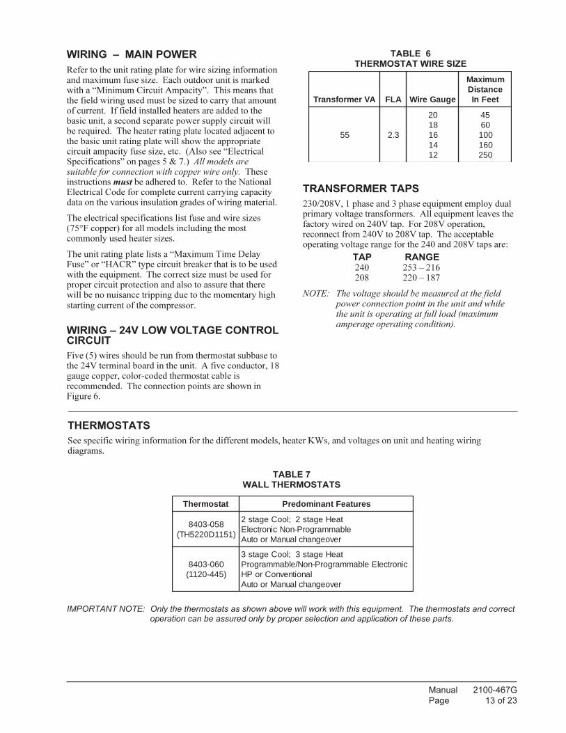
TABLE 6THERMOSTAT WIRE SIZE
AVremrofsnarT ALF eguaGeriW
mumixaMecnatsiDteeFnI
55 3.2
0281614121
5406001061052
TRANSFORMER TAPS
230/208V, 1 phase and 3 phase equipment employ dualprimary voltage transformers. All equipment leaves thefactory wired on 240V tap. For 208V operation,reconnect from 240V to 208V tap. The acceptableoperating voltage range for the 240 and 208V taps are:
TAP RANGE
240 253 – 216 208 220 – 187
NOTE: The voltage should be measured at the fieldpower connection point in the unit and whilethe unit is operating at full load (maximumamperage operating condition).
WIRING – MAIN POWER
Refer to the unit rating plate for wire sizing informationand maximum fuse size. Each outdoor unit is markedwith a “Minimum Circuit Ampacity”. This means thatthe field wiring used must be sized to carry that amountof current. If field installed heaters are added to thebasic unit, a second separate power supply circuit willbe required. The heater rating plate located adjacent tothe basic unit rating plate will show the appropriatecircuit ampacity fuse size, etc. (Also see “ElectricalSpecifications” on pages 5 & 7.) All models aresuitable for connection with copper wire only. Theseinstructions must be adhered to. Refer to the NationalElectrical Code for complete current carrying capacitydata on the various insulation grades of wiring material.
The electrical specifications list fuse and wire sizes(75°F copper) for all models including the mostcommonly used heater sizes.
The unit rating plate lists a “Maximum Time DelayFuse” or “HACR” type circuit breaker that is to be usedwith the equipment. The correct size must be used forproper circuit protection and also to assure that therewill be no nuisance tripping due to the momentary highstarting current of the compressor.
WIRING – 24V LOW VOLTAGE CONTROLCIRCUIT
Five (5) wires should be run from thermostat subbase tothe 24V terminal board in the unit. A five conductor, 18gauge copper, color-coded thermostat cable isrecommended. The connection points are shown inFigure 6.
THERMOSTATS
See specific wiring information for the different models, heater KWs, and voltages on unit and heating wiringdiagrams.
IMPORTANT NOTE: Only the thermostats as shown above will work with this equipment. The thermostats and correctoperation can be assured only by proper selection and application of these parts.
TABLE 7WALL THERMOSTATS
tatsomrehT serutaeFtnanimoderP
850-3048)1511D0225HT(
taeHegats2;looCegats2elbammargorP-noNcinortcelE
revoegnahclaunaMrootuA
060-3048)544-0211(
taeHegats3;looCegats3cinortcelEelbammargorP-noN/elbammargorP
lanoitnevnoCroPHrevoegnahclaunaMrootuA

Manual 2100-467G
Page 14 of 23
EY
1120-445
TH5220D1151
Low Voltage Wiring
L
2
C O
1
Unit Control Panel
BlockYC G R W1 W2 E F
Y1C G R W1OY2 W2 DA
ELAUXRG
EB
RC
3
L
B
Thermostat Subbase
Terminal
HEAT ON UNITS WITH 15 OR MORE KW
YO
Unit 24V
REMOVE JUMPER FOR 2 STAGE ELECTRIC
MIS-2149 C
FIGURE 6LOW VOLTAGE WIRING

Manual 2100-467G
Page 15 of 23
START UP
These units require R-410A refrigerant and Polyol Ester
oil.
GENERAL:
1. Use separate service equipment to avoid cross
contamination of oil and refrigerants.
2. Use recovery equipment rated for R-410A
refrigerant.
3. Use manifold gauges rated for R-410A (800 psi/250
psi low).
4. R-410A is a binary blend of HFC-32 and HFC-125.
5. R-410A is nearly azeotropic - similar to R-22 and
R-12. Although nearly azeotropic, charge with
liquid refrigerant.
6. R-410A operates at 40-70% higher pressure than
R-22, and systems designed for R-22 cannot
withstand this higher pressure.
7. R-410A has an ozone depletion potential of zero,
but must be reclaimed due to its global warming
potential.
8. R-410A compressors use Polyol Ester oil.
9. Polyol Ester oil is hygroscopic; it will rapidly
absorb moisture and strongly hold this moisture in
the oil.
10. A liquid line dryer must be used - even a deep
vacuum will not separate moisture from the oil.
11. Limit atmospheric exposure to 15 minutes.
12. If compressor removal is necessary, always plug
compressor immediately after removal. Purge with
small amount of nitrogen when inserting plugs.
TOPPING OFF SYSTEM CHARGE
If a leak has occurred in the system, Bard
Manufacturing recommends reclaiming, evacuating
(see criteria above), and charging to the nameplate
charge. Topping off the system charge can be done
without problems.
With R-410A, there are no significant changes in the
refrigerant composition during multiple leaks and
recharges. R-410A refrigerant is close to being an
azeotropic blend (it behaves like a pure compound or
single component refrigerant). The remaining
refrigerant charge, in the system, may be used after
leaks have occurred and then “top-off” the charge by
utilizing the charging charts on the inner control panel
cover as a guideline.
REMEMBER: When adding R-410A refrigerant, it
must come out of the charging cylinder/tank as a liquid
to avoid any fractionation, and to insure optimal system
performance. Refer to instructions for the cylinder that
is being utilized for proper method of liquid extraction.
SAFETY PRACTICES:
1. Never mix R-410A with other refrigerants.
2. Use gloves and safety glasses, Polyol Ester oils can
be irritating to the skin, and liquid refrigerant will
freeze the skin.
3. Never use air and R-410A to leak check; the
mixture may become flammable.
4. Do not inhale R-410A – the vapor attacks the
nervous system, creating dizziness, loss of
coordination and slurred speech. Cardiac
irregularities, unconsciousness and ultimate death
can result from breathing this concentration.
5. Do not burn R-410A. This decomposition
produces hazardous vapors. Evacuate the area if
exposed.
6. Use only cylinders rated DOT4BA/4BW 400.
7. Never fill cylinders over 80% of total capacity.
8. Store cylinders in a cool area, out of direct
sunlight.
9. Never heat cylinders above 125°F.
10. Never trap liquid R-410A in manifold sets, gauge
lines or cylinders. R-410A expands significantly
at warmer temperatures. Once a cylinder or line is
full of liquid, any further rise in temperature will
cause it to burst.
START UP NOTES
For improved start up performance, wash the indoor coil
with dishwasher detergent.

Manual 2100-467G
Page 16 of 23
THREE PHASE SCROLL COMPRESSORSTART UP INFORMATION
(Models PA13362-B; PA13422-B, -C; PA13482-B, -C;
PA13602-B, -C)
All units with three phase scroll compressors are
equipped with a three phase line monitor to prevent
compressor damage due to phase reversal.
The phase monitor in this unit is equipped with two
LED’s. If the “Y” signal is present at the phase monitor
and phases are correct, the green LED will light.
If phases are reversed, the red fault LED will be lit and
compressor operation is inhibited.
If a fault condition occurs, reverse tow of the supply
leads to the unit. Do not reverse any of the unit factory
wires as damage may occur.
SEQUENCE OF OPERATION
BLOWER ONLY – When the “Fan” switch on the
room thermostat is placed in the “On” position (circuit
R-G makes), the blower will energize and run until the
“Fan” switch is placed back into the “Auto” position.
This will allow for constant air circulation at a lower
airflow during times when the unit is not in operation
for cooling or heating.
COOLING – On a call for cooling from the room
thermostat (circuit R-Y makes), the blower will energize
(circuit R-G is automatic when R-Y makes) as well as
the compressor, and outdoor fan motor. Note that if the
“Fan” switch on the room thermostat is in the “On”
position and the blower is already in operation, then the
motor will ramp up to the required speed for cooling.
HEATING (1st Stage) – On a call for heating from
the room thermostat (circuit R-W1 makes), the blower
will energize (circuit R-G is automatic when R-W1
makes). This will place the system into heating
operation to maintain the thermostat set temperature.
Note that if the “Fan” switch on the room thermostat is
in the “On” position and the blower is already in
operation, then the motor will ramp up to the required
speed for heating.
HEATING (2nd Stage) – If the operation of the 1st
Stage electric heaters will not maintain the set room
temperature, then the thermostat will call for additional
heat to help maintain the set temperature. On a call for
second stage heating from the room thermostat (circuit
R-W2 makes), additional electric heaters will be
energized if installed.
INDOOR BLOWER MOTOR
These models feature a variable speed (ECM) motor
providing high efficiency, low sound levels and soft
start capabilities. The motor is self adjusting to provide
the proper airflow rate at duct static pressures up to
0.50" WC without user adjustment or wiring changes.
On command from the wall thermostat the motor will
start slowly and ramp up to full speed over a period of
10-15 seconds.
When the thermostat is satisfied the blower will operate
for approximately 1 minute, and then slow down and
stop.
COMPRESSOR CONTROL MODULE
The compressor control is an anti-short cycle/lockout
timer with high and low pressure switch monitoring and
alarm output.
ADJUSTABLE DELAY-ON-MAKE AND BREAKTIMER
On a call for compressor operation the delay-on-make
period begins which will be 10% of the delay-on-break
setting. When the delay-on-make is complete and the
high pressure switch (and low pressure switch if
employed) is closed, the compressor contactor is
energized. Upon shutdown, the delay-on-break timer
starts and prevents restart until the delay-on-break and
delay-on-make periods have expired.
HIGH PRESSURE SWITCH AND LOCKOUTSEQUENCE (Standard Feature)
If the high pressure switch opens, the compressor
contactor will de-energize immediately. The lockout
timer will go into a soft lockout and stay in soft lockout
until the high pressure switch closes and the delay-on-
make time has expired. If the high pressure switch
opens again in this same operating cycle the unit will go
into manual lockout condition and the alarm circuit will
energize. Recycling the wall thermostat resets the
manual lockout.
START UP AND OPERATION

Manual 2100-467G
Page 17 of 23
LOW PRESSURE SWITCH, BYPASS, ANDLOCKOUT SEQUENCE (Standard Feature)
If the low pressure switch opens for more that 120
seconds, the compressor contactor will de-energize and
go into a soft lockout. Regardless the state of the low
pressure switch, the contactor will reenergize after the
delay-on-make time delay has expired. If the low
pressure switch remains open or opens again for longer
than 120 seconds the unit will go into manual lockout
condition and the alarm circuit will energize. Recycling
the wall thermostat resets the manual lockout.
ALARM OUTPUT
Alarm terminal is output connection for applications
where alarm signal is desired. This terminal is powered
whenever compressor is locked out due to HPC or LPC
sequences as described.
NOTE: Both high and low pressure switch controls are
inherently automatic reset devices. The high
pressure switch and low pressure switch cut out
and cut in settings are fixed by specific air
conditioner or heat pump unit model. The
lockout features, both soft and manual, are a
function of the Compressor Control Module.
ADJUSTMENTS
ADJUSTABLE DELAY-ON-MAKE ANDDELAY-ON-BREAK TIMER
The potentiometer is used to select Delay-on-Break time
from 30 seconds to 5 minutes. Delay-on-Make (DOM)
timing on power-up and after power interruptions is
equal to 2 minutes plus 10% of Delay-on-Break (DOB)
setting:
0.5 minute (30 seconds) DOB = 123 second DOM
1.0 minute (60 seconds) DOB = 126 second DOM
2.0 minute (120 seconds) DOB = 132 second DOM
3.0 minute (160 seconds) DOB = 138 second DOM
4.0 minute (240 seconds) DOB = 144 second DOM
5.0 minute (300 seconds) DOB = 150 second DOM
FIGURE 7
LOW AMBIENT CONTROL WIRING
LOW AMBIENT CONTROL
Optional Low Ambient Control
An optional low ambient control is available for both
factory and field installed options. The low ambient
control is to be applied to the PA13 Series models when
operation below 55° outdoor conditions are anticipated.
Without this device, the evaporating pressure would fall
off, and the indoor coil would ice over.
The fan cycling control cycles the fan motor on, once the
liquid refrigerant pressure reaches 350 psig, and off, once
it has dropped to 225 psig. It will continue to cycle
between these parameters depending on outdoor
temperatures and the load/stage of the system.
This cycling maintains a minimum liquid pressure
affecting the minimum suction pressure. This effect
insures an evaporating temperature that is slightly above
the point of ice formation on the evaporator.
This field installed option is Bard Part #CMA-28. See
Figure 7.

Manual 2100-467G
Page 18 of 23
FAN BLADE SETTINGS
Shown in Figure 8 are the correct fan blade setting
dimensions for proper air delivery across the outdoor
coil.
Any service work requiring removal or adjustment in
the fan and/or motor area will require that the
dimensions below be checked and blade adjusted in or
out on the motor shaft accordingly.
"B"
MD-1417BC
SERVICE AND TROUBLESHOOTING
SERVICE HINTS
1. Caution homeowner to maintain clean air filters at
all times. Also, not to needlessly close off supply
and return air registers. This reduces airflow
through the system which shortens equipment
service life as well as increasing operating costs.
2. Check all power fuses or circuit breakers to be sure
that they are the correct rating.
3. Periodic cleaning of the outdoor coil to permit full
and unrestricted airflow circulation is essential.
PRESSURE SERVICE PORTS
High and low pressure service ports are installed on all
units so that the system operating pressures can be
observed. Pressure tables can be found later in this
manual covering all models on cooling cycle. It is
imperative to match the correct pressure table to the
unit by model number.
REFRIGERANT CHARGE
The correct system R-410A charge is shown on the unit
rating plate.
You can reference Tables 10 & 11 to validate proper
system performance. However, it is recommended that
if incorrect charge is suspected, the system be
reclaimed, evacuated and charged to the nameplate
quantity and type.
The nameplate charge quantity is optimized for thermal
performance and efficiency of this self-contained
package system.
TABLE 8
FAN BLADE SETTING DIMENSIONS
ledoM "A"noisnemiD
4231AP
"¼3
0331AP
6331AP
2431AP
8431AP
0631AP
“A”
ledoMdetaR
PSEXAMPSE
2
suounitnoCwolfriA
3
detaRgnilooC
MFC
4
detaRgnitaeH
MFC
4231AP 01.0 05.0 006 008 008
0331AP 51.0 05.0 057 0001 0001
6331AP 51.0 05.0 528 0011 0011
2431AP 02.0 05.0 529 0041 0041
8431AP 02.0 05.0 5201 0551 0551
0631AP 02.0 05.0 0511 0561 0561
TABLE 9
INDOOR BLOWER PERFORMANCE 1
1 Motor will deliver consistent CFM through voltage supply range with no deterioration
(197-253V for all 230/208V models).
2 Continuous CFM is the total air being circulated during continuous (manual fan) mode.
3 Will occur automatically with a call for "Y" for cooling mode operation.
4 Will occur automatically with a call for "W1" for heating mode operation.
FIGURE 8
FAN BLADE SETTING

Manual 2100-467G
Page 19 of 23
(Co
nti
nu
ed
on
Pag
e 2
0 in
Tab
le 1
1)
led
oM
riA
nrute
Rer
utarep
meTer
usserP
°56°07
°57°08
°58°09
°59°001
°501°011
°511°021
°521
4231A
P
57°
BD
26°
BW
ediS
woLedi
Shgi
H521832
721262
921682
131013
331433
531853
731283
831704
041234
241754
341284
541705
741235
08°
BD
BW
°76edi
SwoL
ediS
hgiH
431442
631962
831392
041813
241343
441763
641293
841814
051344
151964
351494
551025
751645
58°
BD
27°
BW
ediS
woLedi
Shgi
H441352
641872
841403
151923
351553
551083
751604
951234
161954
361584
561215
761835
961565
0331A
P
57°
BD
26°
BW
ediS
woLedi
Shgi
H621642
821762
131982
331013
531233
731353
931473
141204
341924
541754
841484
051215
251935
08°
BD
76°
BW
ediS
woLedi
Shgi
H531252
731472
041692
241813
441043
741263
941483
151214
351044
651964
851794
061525
261355
58°
BD
27°
BW
ediS
woLedi
Shgi
H541162
841482
051603
351923
551253
851573
061793
361724
561654
761584
071415
271345
471375
6331A
P
57°
BD
26°
BW
ediS
woLedi
Shgi
H521742
721172
821592
031023
231443
331963
531393
631814
831344
931864
141494
241915
08°
BD
76°
BW
ediS
woLedi
Shgi
H431352
631872
731303
931823
141353
241873
441304
641924
741554
941084
051605
251235
58°
BD
27°
BW
ediS
woLedi
Shgi
H441262
641882
841413
941933
151563
351193
551714
751444
851174
061794
261425
361155
TA
BL
E 1
0
PR
ES
SU
RE
TA
BL
E
COOLING
Air
Te
mp
era
ture
En
teri
ng
Ou
tdo
or
Co
il D
eg
ree
F
LO
W S
IDE
PR
ES
SU
RE
+2
PS
IG
HIG
H S
IDE
PR
ES
SU
RE
+5
PS
IG
Ta
ble
s b
ase
d u
po
n r
ate
d C
FM
(a
irflo
w)
acro
ss th
e e
va
po
rato
r co
il.
If in
co
rre
ct
ch
arg
e s
usp
ecte
d (
mo
re t
ha
n +
2 p
sig
su
ctio
n,
+5
psig
liq
uid
),
it is r
eco
mm
en
de
d r
efr
ige
ran
t ch
arg
e b
e r
ecla
ime
d, syste
m e
va
cu
ate
d a
nd
ch
arg
ed
to
se
ria
l p
late
qu
an
tity
.

Manual 2100-467G
Page 20 of 23
TA
BL
E 1
1
PR
ES
SU
RE
TA
BL
E
COOLING
Air
Te
mp
era
ture
En
teri
ng
Ou
tdo
or
Co
il D
eg
ree
F
LO
W S
IDE
PR
ES
SU
RE
+2
PS
IG
HIG
H S
IDE
PR
ES
SU
RE
+5
PS
IG
led
oM
riA
nrute
Rer
utarep
meTer
usserP
°56°07
°57°08
°58°09
°59°001
°501°011
°511°021
°521
2431A
P
57°
BD
26°
BW
ediS
woLedi
Shgi
H621242
821562
921882
131113
231433
431753
631083
731904
831734
041664
141494
241325
341155
08°
BD
BW
°76edi
SwoL
ediS
hgiH
531842
731272
831592
041913
241343
341663
541093
641914
841844
941874
151705
251635
351565
58°
BD
27°
BW
ediS
woLedi
Shgi
H541752
741182
941603
151033
251553
451973
651404
751434
951464
061494
261525
361555
561585
8431A
P
57°
BD
26°
BW
ediS
woLedi
Shgi
H521932
721362
821782
921113
031533
231953
331383
431014
631834
731564
931294
041025
241745
08°
BD
76°
BW
ediS
woLedi
Shgi
H431542
531072
731492
831913
931443
141863
241393
441124
541944
741774
841505
051335
251165
58°
BD
27°
BW
ediS
woLedi
Shgi
H441452
541972
741503
841033
051653
151183
351704
451634
651564
851494
061325
161255
361185
0631A
P
57°
BD
26°
BW
ediS
woLedi
Shgi
H421422
521452
621582
721513
821543
921573
031604
131134
131654
231084
331505
431035
08°
BD
76°
BW
ediS
woLedi
Shgi
H331032
431162
531292
631323
731453
831583
931614
041244
141764
141394
241815
341445
58°
BD
27°
BW
ediS
woLedi
Shgi
H341832
441072
541203
641433
741663
841893
941134
051754
151484
251015
351735
451365
Ta
ble
s b
ase
d u
po
n r
ate
d C
FM
(a
irflo
w)
acro
ss th
e e
va
po
rato
r co
il.
If in
co
rre
ct
ch
arg
e s
usp
ecte
d (
mo
re t
ha
n +
2 p
sig
su
ctio
n,
+5
psig
liq
uid
),
it is r
eco
mm
en
de
d r
efr
ige
ran
t ch
arg
e b
e r
ecla
ime
d, syste
m e
va
cu
ate
d a
nd
ch
arg
ed
to
se
ria
l p
late
qu
an
tity
.

Manual 2100-467G
Page 21 of 23
SUCTION AND DISCHARGE TUBEBRAZING
Compliant Scroll compressors have copper plated steel
suction and discharge tubes. These tubes are far more
rugged and less prone to leaks than copper tubes used on
other compressors. Due to different thermal properties
of steel and copper, brazing procedures may have to be
changed from those commonly used.
• To disconnect: heat joint Areas 2 and 3 slowly and
uniformly until braze material softens and the tube
can be pulled out of suction fitting. (See Figure 9.)
• To connect:
– Recommended brazing materials: silfos with
minimum 5% silver or silver braze material with
flux.
– Reinsert tube into fitting.
– Heat tube uniformly in Area 1 moving slowly to
Area 2. When joint reaches brazing
temperature, apply brazing material. (See
Figure 9)
– Heat joint uniformly around the circumference
to flow braze material completely around the
joint.
– Slowly move torch into Area 3 to draw braze
material into joint. (See Figure 9.)
– Do not overheat joint.
FIGURE 9
BRAZING DIAGRAM
Manual 2100-467G
Page 22 of 23
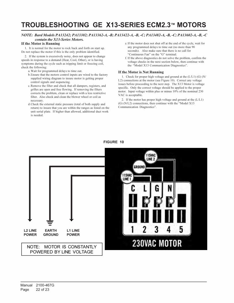
FIGURE 10
↓ ↓
NOTE: Bard Models PA13242; PA13302; PA13362-A, -B; PA13422-A, -B, -C; PA13482-A, -B, -C; PA13602-A, -B, -C
contain the X13-Series Motors.
TROUBLESHOOTING GE X13-SERIES ECM2.3™ MOTORS
If the Motor is Running
1. It is normal for the motor to rock back and forth on start up.
Do not replace the motor if this is the only problem identified.
2. If the system is excessively noisy, does not appear to change
speeds in response to a demand (Heat, Cool, Other), or is having
symptoms during the cycle such as tripping limit or freezing coil,
check the following:
a. Wait for programmed delays to time out.
b.Ensure that the motors control inputs are wired to the factory
supplied wiring diagram to insure motor is getting proper
control signals and sequencing.
c. Remove the filter and check that all dampers, registers, and
grilles are open and free flowing. If removing the filters
corrects the problem, clean or replace with a less restrictive
filter. Also check and clean the blower wheel or coil as
necessary.
d.Check the external static pressure (total of both supply and
return) to insure that you are within the ranges as listed on the
unit serial plate. If higher than allowed, additional duct work
is needed.
e. If the motor does not shut off at the end of the cycle, wait for
any programmed delays to time out (no more than 90
seconds). Also make sure that there is no call for
“Continuous Fan” on the "G" terminal.
f. If the above diagnostics do not solve the problem, confirm the
voltage checks in the next section below, then continue with
the “Model X13 Communication Diagnostics”.
If the Motor is Not Running
1. Check for proper high voltage and ground at the (L/L1) (G) (N/
L2) connections at the motor (see Figure 10). Correct any voltage
issues before proceeding to the next step. The X13 Motor is voltage
specific. Only the correct voltage should be applied to the proper
motor. Input voltage within plus or minus 10% of the nominal 230
VAC is acceptable.
2. If the motor has proper high voltage and ground at the (L/L1)
(G) (N/L2) connections, then continue with the “Model X13
Communication Diagnostics”.
L2 LINE
POWER
EARTH
GROUND
L1 LINE
POWER
NOTE: MOTOR IS CONSTANTLY
POWERED BY LINE VOLTAGE

Manual 2100-467G
Page 23 of 23
FIGURE 11
TROUBLESHOOTING GE X13-SERIES ECM2.3™ MOTORS CONT’D.
Model X13 Communication Diagnostics
The X13 motor is communicated through 24 VAC low voltage
(Thermostat Control Circuit Wiring).
1. Start with unit wiring diagram to confirm proper
connections and voltage (see Figure 11).
2. Initiate a demand from the thermostat and check the
voltage between the common and the appropriate motor
terminal (1-5). ("G" input is typically on terminal #1, but
refer to wiring diagram!)
a. If the low voltage communication is not present, check
the demand from the thermostat. Also check the
output terminal and wire(s) from the terminal strip or
control relay(s) to the motor.
b. If the motor has proper high voltage as identified
above (Motor not Running #1), and proper low voltage
to a programmed terminal, and is not operating, the
motor is failed, and will require replacement.
24VAC "R" Signal through thermostat output.
24VAC Common
24VAC Common
24VAC "R" Signal through thermostat output.