2.12 introduction to robotics - fall 2016 - hw2.12 introduction to robotics - fall 2016 - hw1...
TRANSCRIPT

MIT - Mechanical Engineering Department
2.12 Introduction to Robotics - Fall 2016 - HW1Released: September 15, 2016 Due: September 21, 2016
Notes:· Turn in individual problems in separate pages and put your name on each page.· Show the process to get to the answer and not just the solution.· Clearly highlight solutions, i.e., draw a rectangle around them.
Problem 1
Single Axis Drive System
In this problem we will review the basics of DC motors and their governing equations. We start by review-ing the equations relating voltage across the armature (u), output torque (⌧m) and angular velocity (!m).Consider the torque/velocity profile of the motor in Figure 1.
Figure 1: Torque/velocityprofile of the motor.
a. Find the motor constant, torque constant, and the armature resistance of the motor.b. When the motor rotates at 100 rad/sec, what is the back emf voltage induced at the armature.c. When the motor is producing half its maximum torque, how much power is being dissipated as heat
in the motor windings.
Consider now the system in Figure 2. Let’s denote the combined inertia of the motor + shaft + small gear asIm and the combined inertia of the load + large gear as Ia. For simplicity, assume that the motor is hangingvertically (neglect gravity) and that friction is also negligible.
Figure 2: Motor and load.
1

d. If the angular velocity of the motor is almost zero, find the gear ratio r that maximizes the angularacceleration of the joint axis. Evaluate r for Im = 1⇥ 10�4 kgm2 and Ia = 1.6⇥ 10�1 kgm2.
e. What is that maximum angular acceleration when the armature voltage is 30 Volts?
To power the motor, consider the circuit in Figure 3, where we provide a constant voltage V to the motorconnected series with its resistance and a transistor. You learned in class that by controlling the transistorvoltage Vce and current Ic we can provide power to the motor in a controlled way.
Figure 3: Linear amplifier.
f. How much voltage do we need to supply to the armature to rotate the motor at 100 rad/sec if the motortorque constant is 5.0⇥ 10�2 Nm
A ?
g. We want to choose a suitable transistor from a catalog to work with the circuit above. Consider theON-OFF cycle of the transistor is Figure 4. Assume that the maximum voltage is 10 V, the maximumcurrent is 0.5 A, and that the profiles of voltage Vce and current Ic are piece-wise linear, how muchheat (cal) is generated in the transistor per second assuming that the transistor is used for a uni-polarPWM amplifier of 10 kHz PWM frequency?
Figure 4: Switch-On/Off Cycle.
2

Problem 2
Motor-Encoder Pair
We are looking to provide a load with a maximum angular velocity 200 RPM when free spinning (i.e., noexternal forces) and a maximum torque of 20 Nm when stalled. Our task is to choose a motor (no gears), anencoder and a suitable encoder buffer chip.
a. If we have a power supply that provides 12 volts, find the motor armature resistance and torqueconstant. What is the expected maximum output power from this motor?
b. If we require a sub 0.1� resolution in resolving the angular position of the motor, how many bits ofresolution do we need for a relative optical encoder?
c. An encoder buffer chip is often used to read the encoder signal, counting encoder ticks, and keep trackof the motor position. Given the motor and encoder specs we want, what is the minimum samplingrate that the buffer chip needs to operate?
Problem 3
Differential Drive Vehicle Kinematics
The car in Figure 5 has wheels with radius r = 5 cm, and a wheel-to-wheel distance of 2b = 40 cm. Wedenote the angular velocity of the left and right wheels as !R = ✓̇R and !L = ✓̇L respectively and assumewe can directly measure these values. The mass of the vehicle is 1 kg.
Figure 5: Car in 2D plane.
a. Given the wheel velocity profiles Figure 6, and assuming the car starts at (x, y,�) = (0.1m, 0.1m, 0.1rad),plot the position and orientation of the vehicle for the time period of the motion. In case it helps, theseare the expressions for the speed and curvature of the trajectory of the vehicle:
Linear Velocity: v =r
2(!r + !l)
Curvature: =!r � !l
b(!r + !l)
b. As in lab 2, we are interested in driving the car along the U-shaped trajectory in Figure 7. Findvelocity profiles for the wheels of the robot such that the speed in the straight sections is 10⇡ cm/sand on the half circle section 5⇡ cm/s. The robot starts at the lower left corner.
3

Figure 6: Angular velocities of right and left wheels.
Figure 7: U Shape trajectory.
Problem 4
Kinematics of a Planar 3-DOF Manipulator
The planar manipulator in Figure 8 is composed of two revolute joints, q1 and q3 with full range of motion,and one prismatic joint q2, with range in [0, l2], and 0 < l2 < l1.
a. Find the algebraic relationship between the joint coordinates (q1, q2, q3) of the manipulator and thecartesian coordinates (x, y,�) of the end effector at C. Is this mapping 1 to 1? i.e, a choice of(q1, q2, q3) implies a unique (x, y,�).
b. Sketch by hand the workspace and the dexterous workspace of the robot.
c. Is the inverse kinematics map 1 to 1? A sketch or geometric argument is sufficient.
d. Is there any benefit to this manipulator over the simpler 2-link manipulator we saw in class?
[2.120 Students Only]
e. Find the algebraic expression for the inverse kinematics and discuss the multiplicity of solutions.
4
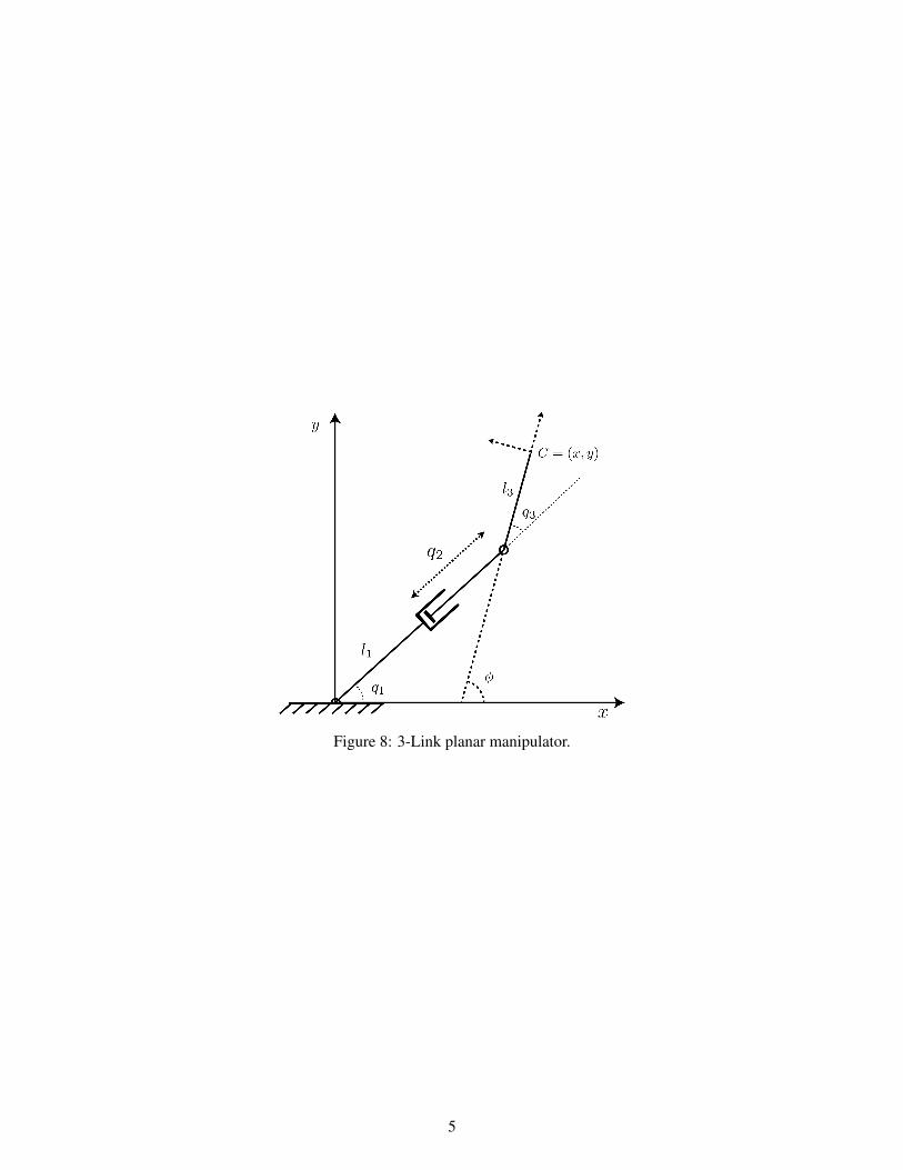
Figure 8: 3-Link planar manipulator.
5