2137 panasonic v1 4 sipguide
TRANSCRIPT
The purpose of this configuration guide is to describe the steps needed to configure the Panasonic KX-NCP500 IP PBX V2.0502 for proper operation with Optimum Business SIP Trunking.
SIP Trunking using Optimum Business SIP Trunk Adaptor and the Panasonic KX-NCP500 IP PBX V2.0502
Goal
Prerequisites
Please follow the instructions in the Optimum Business SIP Trunk Set-Up Guide. The Set-Up Guide was left by the Optimum Business technician at installation. If you do not have the Set-Up Guide, go to www.optimumbusiness.com/SIP to download a copy.
The steps on the next page describe the minimum configuration required to enable the PBX to use Optimum Business SIP Trunking for inbound and outbound calling. Please refer to the Panasonic KX-NCP500 product documentation for more information on advanced PBX features.
The configuration described here assumes that the PBX is already configured and operational with station side phones using assigned extensions or DIDs. This configuration is based on KX-NCP500 V2.0502.
Panasonic KX-NCP500 Configuration
PANASONIC
V 1.4 1

1. The PBX, the phones and the Optimum Business SIP Trunk Adaptor should be on the same LAN segment. The PBX is shipped with 2 default IP addresses for the LAN port, one for the IPCMPR card (192.168.0.101/24) and the other the VoIP DSP card (192.168.0.102/24). The IPCMPR card is used to communicate with the SIP Trunk Adaptor using SIP protocol and to communicate with the phones. The phones in this test setup communicate with the PBX using MGCP protocol. The VoIP DSP card is used to send and receive media traffic between the phones and the PBX. The PBX should have its gateway set to the Optimum Business SIP Trunk Adaptor’s port 1 LAN IP address (i.e.: 192.168.0.1/24).
2. To configure the PBX, a configuration GUI, PBX Unified Maintenance Console, is needed. From the CD that shipped with the PBX, install the configuration GUI by running the “UPCMCv5.1.2.3_US_R1.exe” program.
3. Invoke the PBX Unified Maintenance Console program from the PC and you should see a screen with a different level of Programmer Code and Password. Always use the Installer level of Programmer Code and Password when configuring the PBX. Click the “OK” button to continue.
4. Enter the installer-level Programmer Code (i.e.: “INSTALLER”) in the “Enter Programmer Code” field and click the “OK” button.
V 1.4 2
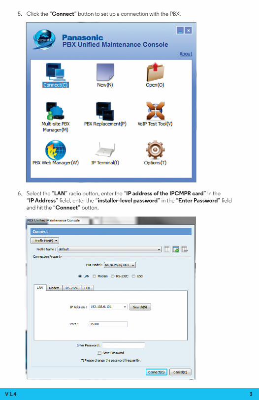
5. Click the “Connect” button to set up a connection with the PBX.
6. Select the “LAN” radio button, enter the “IP address of the IPCMPR card” in the “IP Address” field, enter the “installer-level password” in the “Enter Password” field and hit the “Connect” button.
V 1.4 3
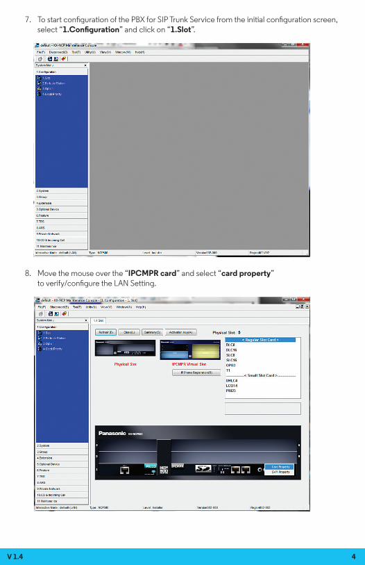
7. To start configuration of the PBX for SIP Trunk Service from the initial configuration screen, select “1.Configuration” and click on “1.Slot”.
8. Move the mouse over the “IPCMPR card” and select “card property” to verify/configure the LAN Setting.
V 1.4 4
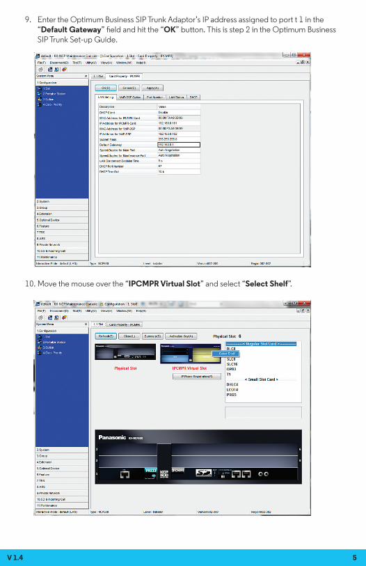
9. Enter the Optimum Business SIP Trunk Adaptor’s IP address assigned to port t 1 in the “Default Gateway” field and hit the “OK” button. This is step 2 in the Optimum Business SIP Trunk Set-up Guide.
10. Move the mouse over the “IPCMPR Virtual Slot” and select “Select Shelf”.
V 1.4 5

11. Move the mouse over the “V-SIPGW16” card and select “OUS” as we need to take the V-SIPGW16 card out of service before making changes to the parameters.
12. Move the mouse over the “V-SIPGW16” card and select “shelf property” to access the parameters on the SIP gateway.
V 1.4 6

13. Note the warning messages about taking the V-SIPGW cards out of service before changing the parameters would appear if you had not taken the card out of service. Click “OK” to continue.
14. Enter “5060” in the “SIP Client Port Number” field. Make sure the “NAT Traversal” field is set to “Off” and the “STUN Ability” field is set to “Disable”. Hit the “OK” button.
V 1.4 7

15. Select “1.Configuration”, select “1.Slot” and select “Card Property” to manually set the DNS server addresses.
16. Click the “Common Settings” button. The “DNS Server IP Address Method” field should be set to “Manual”. Enter the DNS IP addresses in the “Manual Preferred DNS Server IP Address” field and the “Manual Preferred DNS Server IP Address” field and hit the “OK” button.
V 1.4 8

17. Select “1.Configuration”, select “1.Slot” and select “Port Property” to access SIP trunk configuration parameters.
18. Select the “Main” tab to start configuring the SIP trunk parameters. a. From entry number 1 (Slot 1 – Port 1), select “Basic channel” in the “Channel Attribute” field, enter a descriptive name for the Optimum Business SIP Trunk Adaptor in the “Provider Name” field, enter the Optimum Business SIP Trunk Adaptor’s IP address in both the “IP Address” field and the SIP Service Domain field, enter “5060” in the “SIP Server Port Number” field and enter the subscriber number in the “Subscriber Number” field. Note that the subscriber number we entered in this example is the same as the Pilot DID. b. From entry number 2 to 5 (Slot 1 – Port 2 to 5), select “Additional channel for Ch1” in the “Channel Attribute” field and enter “5060” in the “SIP Server Port Number” field. Note that the number of additional channels to add depends on the number of SIP trunks you are licensed to have. In this example, the number of licensed SIP trunks is 4. c. Hit the “OK” button.
V 1.4 9

19. Select the “Account” tab to configure User Name, Authentication ID and Authentication Password for the SIP Trunk Service. From entry number 1 (Slot 1 – Port 1), enter username in the “User Name” field, enter password in the “Authentication Password” field and hit the “OK” button. This is step 3 of the Optimum SIP Trunk Set-up Guide. In this example, the pilot DID, 6316769608, is used for both the username and the password. Note that these configurations are used only when the Optimum Business SIP Trunk Adaptor is configured to expect SIP registration from the PBX.
20. Select the “Register” tab to configure the PBX for SIP registration mode or static IP address mode. From entry number 1 (Slot 1 – Port 1), select “Enable” in both the “Register Ability” field and the “Un-Register Ability when port INS” field if the Optimum Business SIP Trunk Adaptor is configured to receive SIP registration from the PBX; select “Disable” if the Optimum Business SIP Trunk Adaptor is configured to communicate with the PBX via the PBX’s static IP address. Note: When using registration mode, all CLIP ID’s must match the Pilot DID. In non-registration mode, the CLIP ID’s can be any DID on the SIP Trunk.
V 1.4 10
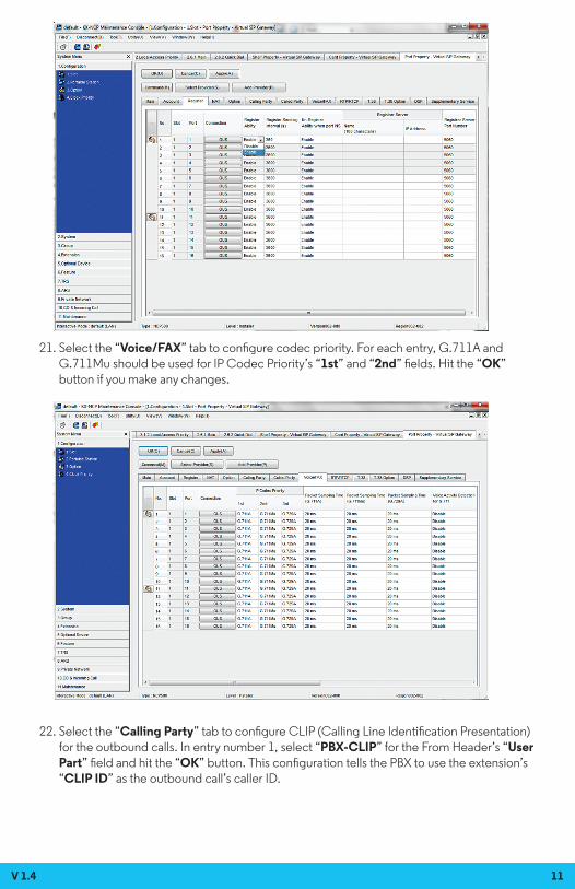
21. Select the “Voice/FAX” tab to configure codec priority. For each entry, G.711A and G.711Mu should be used for IP Codec Priority’s “1st” and “2nd” fields. Hit the “OK” button if you make any changes.
22. Select the “Calling Party” tab to configure CLIP (Calling Line Identification Presentation) for the outbound calls. In entry number 1, select “PBX-CLIP” for the From Header’s “User Part” field and hit the “OK” button. This configuration tells the PBX to use the extension’s “CLIP ID” as the outbound call’s caller ID.
V 1.4 11

23. Select “1.Configuration”, select “1.Slot” and click on the “IP Phone Registration” button to see the extensions that are used by the registered phones.
24. Select “10.CO Line & Incoming Call”, select “DID Table” to assign DID for each extension in use. For each extension in use, enter the assigned DID number in the “DID Number” field, enter a DID name in the “DID Name” field, enter the same extension number in the “Day/Lunch/Break/Night” fields. Hit the “OK” button after you finish assigning DIDs for all the extensions.
V 1.4 12

25. Select “4.Extension”, select “1.Extension Settings” and select “ISDN CLIP” to assign CLIP ID (Caller ID) for each extension. For each extension in use, enter the extension name in the “Extension Name” field and enter a DID number in the “CLID ID” field. Hit the “OK” button after you finish assigning CLIP ID for all the extensions. When using registration mode, all CLIP ID’s must match the Pilot DID. In non-registration mode, the CLIP OD’s may match any DID on the SIP Trunk.
26. Select “10.CO Line & Incoming Call”, select “1.CO Line Settings” to prepare for dialing “9” to access the SIP trunks. For each SIP trunk in use (i.e.: the “Shelf” field set to “Virtual”), enter “SIP trunk” or some descriptive name in the “CO Name” field and enter “1” or some other number in the “Trunk Group Number” field. Hit the “OK” button after you finish assigning a same trunk group number for each SIP trunk. Note that the trunk group number must be the same for all the SIP trunks.
V 1.4 13

27. Select “3.Group”, select “1.Trunk Group” and select “Local Access Priority” to configure dialing “9” to access the SIP trunks only. Select the “trunk group number and SIP trunk” in the “Trunk Group No. & Name” field for the Priority 1 entry, select blank in the “Trunk Group No. & Name” field for the Priority 2 entry and hit the “OK” button.
V 1.4 14
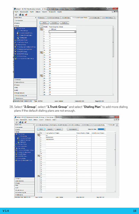
28. Select “3.Group”, select “1.Trunk Group” and select “Dialing Plan” to add more dialing plans if the default dialing plans are not enough.
V 1.4 15
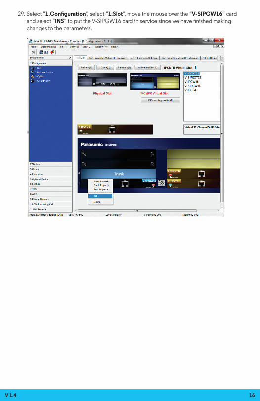
29. Select “1.Configuration”, select “1.Slot”, move the mouse over the “V-SIPGW16” card and select “INS” to put the V-SIPGW16 card in service since we have finished making changes to the parameters.
V 1.4 16

30. Select “1.Configuration”, select “1.Slot” and select “Port Property” and the SIP trunk configurations should reflect the INS (in service) status. Note that you may need to reboot the PBX as some changes may require a reset to take effect.
31. To enable the auto attendant, go to page 1.3 and assign a DID to extension 501.
V 1.4 17

Then go to page 5.3.2 to assign button presses to extensions.
32. To enable Simple Voice Messaging (SVM), go to page 4.1.2 and do the following: Select the extension that you want to modify, and then select which mode you want to modify and then enter “591” in the box to the right. Ensure that the checkbox marked “For both external calls and internal calls” is checked if you don’t want to configure these separately.
V 1.4 18

Note: The Auto Attendant and SVM are both capable of detecting in-band and out-of-band DTMF tones. No additional configuration changes are needed to enable this capability. See the manufacturer’s user guide for recording a greeting for the Auto Attendant, the SVM, and basic voicemail usage. This is not covered by this document.
V 1.4 19