22-1799-18 product data - trane · ©2013trane pub. no. 22-1799-18 product data 4dcy4024 through...
TRANSCRIPT
© 2013Trane Pub. No. 22-1799-18
Product Data4DCY4024 through 4DCY4060
Single Packaged Convertible Dual Fuel14 SEER 2 - 5 Ton, 40 - 120 MBTUR-410A
22-1799-18

2
Single Packaged Convertible Dual Fuel SystemTrane offers a complete family of dual fuel heating and cooling systems, de-signed to keep you comfortable all year long, regardless of the weather, while keeping your operating costs as low as possible. The heat pump operates ef-ficiently as both an air conditioner and a heater. In the summer, the heat pump cools your home just like any other air conditioner by pulling the heat from the inside and releasing it outdoors. In the winter, it captures the heat that is al-ways present in the outdoor air and transfers it indoors. The gas furnace pro-vides additional heating capacity for cooler weather.
Single Packaged Dual Fuel Systems are unmatched in quality and reli-ability. All major components on these products, including the compressor, have been designed and manufactured for maximum service. Every Climatuff® compressor is designed and manufac-tured to exacting specifications. Each design is life tested in extreme envi-ronments to ensure reliable and long lasting operation in normal applications. Each compressor has internal motor protection for added reliability.
Single Packaged Convertible Dual Fuel Systems are easy and versatile to install. Because cooling and heating functions are all contained in a single cabinet, a Trane packaged dual fuel system is easy to install and service. It can be flush mounted beside your home at ground level or placed on the roof for horizontal or downflow installation. When connected to a *CONT402, 802, or 803 comfort control, and air distribution ducts, you have a highly efficient, total home comfort system.
It's Hard to Stop a Trane.
Introducing the new TRANE Single Packaged Convertible Dual Fuel System.

3
Contents
Optional Equipment Listing 4
General Data 5
Indoor Blower Performance 8
Typical Wiring 16
Optional Equipment 14
Dimensional Data 19
Mechanical Specifications 25

4
Optional Equipment Listing
OPTIONAL EQUIPMENT FOR 4DCY4 PACKAGED UNITS (check mark [✓] indicates accessories included)
Hinged Filter Access Door (4DCY4024-036) 8 ................................................................ BAYACCDOR1A[ ]Hinged Filter Access Door (4DCY4042-060) 8 ................................................................ BAYACCDOR2A[ ]Roof Curb Full Perimeter (4DCY4024-036) 3 ...................................................................BAYCURB050A[ ]Roof Curb Full Perimeter (4DCY4042-060) 3 ...................................................................BAYCURB051A[ ]Roof Curb Utility Extension Kit (BAYCURB050A)....................................................................BAYUTIL101B[ ]Roof Curb Utility Extension Kit (BAYCURB051A)....................................................................BAYUTIL102B[ ]0-25% Manual Fresh Air Damper (4DCY4024-36) 1. ..........................................................BAYOSAH001A[ ]0-25% Manual Fresh Air Damper (4DCY4042-060) 1. ........................................................BAYOSAH002A[ ]Motorized Fresh Air Damper (4DCY4024-36) 1. ............................................................... BAYDMPR101A[ ]Motorized Fresh Air Damper (4DCY4042-060) 1. .............................................................. BAYDMPR102A[ ]16" Round Duct Adapter (2 per box) (4DCY4024-36) 6 .................................................... BAYSQRD001A[ ]18" Round Duct Adapter (2 per box) (4DCY4024-060) 6 .................................................. BAYSQRD002A[ ]0-100% Mod Economizer w/Baro. Relief (4DCY4024-36) 124 ....................................... BAYECON101B[ ]0-100% Mod. Economizer w/Baro. Relief (4DCY4042-060) 124. .................................... BAYECON102B[ ]0-100% Horizontal Economizer (4DCY4024-36) 12 . ....................................................... BAYECON200A[ ]0-100% Horizontal Economizer (4DCY4042-060) 12 . ..................................................... BAYECON201A[ ]Economizer Relay Kit (required for Heat Pump applications) ................................................BAYRLAY004A[ ] Enthalpy Control for Economizer (solid state). ......................................................................BAYENTH001A[ ]Remote Potentiometer (All-BAYECON***A) .............................................................................BAYSTAT023[ ]1"-2" Filter Frame (4DCY4024-36) (20 x 25 filter not included) 1. ........................................ BAYFLTR101B[ ]1"-2" Filter Frame (4DCY4042-60) (20 x 20 & 20 x18 filter not included) 1. ......................... BAYFLTR201B[ ]Head Pressure Control (Low Ambient Cool) (208/240v) Kit 5. ...........................................BAYLOAM105A[ ] Quick Start Kit (4DCY4-‡1) ..................................................................................................BAYQSKT300A[ ]Crankcase Heater Recip (4DCY4024‡1 (230v) 5. ..............................................................BAYCCHT101A[ ]Crankcase Heater Scroll(4DCY4036,48, 60‡1/3)(230v) 5. .................................................BAYCCHT102A[ ]Adapter Curb 4DCY4024-36 to BAYCURB030,38 .............................................................. BAYADAP050A[ ] Adapter Curb 4DCY4024-36 to BAYCURB033 ................................................................... BAYADAP051A[ ] Adapter Curb 4DCY4042-60 to BAYCURB030,38 .............................................................. BAYADAP052A[ ] Adapter Curb 4DCY4042-60 to BAYCURB033 ................................................................... BAYADAP053A[ ] Adapter Curb 4DCY4042-60 to BAYCURB034 ................................................................... BAYADAP054A[ ]12" Duct Shroud Covers Horizontal *DCY4024-607. ..........................................................BAYCOVR112A[ ]18" Duct Shroud Covers Horizontal *DCY4024-60 7. .........................................................BAYCOVR118A[ ] Extreme Condition Mounting Kit - All BAYCURB & BAYADAP .............................................BAYEXMK001A[ ]Extreme Condition Mounting Kit - All BAYUTIL ....................................................................BAYEXMK002B[ ] Extreme Condition Mounting Kit - All Slab Mounts ...............................................................BAYEXMK003A[ ]Lifting Lug Kit ...........................................................................................................................BAYLlFT002B[ ]LP Conversion Kit (All 40K, 120K Models) ...........................................................................BAYLPKT100A[ ]LP Conversion Kit (All 64K, 96K Models) .............................................................................BAYLPKT101A[ ]LP Conversion Kit (All 75K Models).......................................................................................BAYLPKT102A[ ]
NOTES: 1 Must use internal filter frame when economizer or fresh air kit is used. 2 Dry bulb control standard with economizer. 3 Ships knocked down. 4 Downflow only. 5 Low Ambient cooling requires crankcase heater (BAYCCHT----A). 6 It is the responsibility of the installing dealer to properly size the ductwork for each specific application. 7 BAYCOVR112,118A will not cover BAYSQRD002A applications. 8 BAYACCDOR1A requires BAYFLTR101B & BAYACCDOR2A requires BAYFLTR201B. They are not backward com-
patible to BAYFLTR101/201A. ‡ = A or B

5
General Data4DCY4024A1064B
208-230/1/6023600760
2.16212/14.0
68
22400 / 3.71.77
11600 / 2.381.248.0
640005150035 / 654800041200
79NATURAL
1/2208-230/1/60
16.12525
RECIPROCATING208-230/1/60
8.3 / 57.8SPINE-FIN
2 / 2413.323/8
EXPANSION VALVEPLATE FIN
3 / 153.543/8
EXPANSION VALVE3/4 FEMALE NPT
PROPELLER23.4
DIRECT / 12590
1/12 / 810208-230/1/60
0.54 / 0.95CENTRIFUGAL
10 X 10DIRECT / VARIABLE
SEE FAN PERFORMANCE TABLE1/2 / VARIABLE200-230/1/60
4.3 / 4.3CENTRIFUGAL
DIRECT / 21/45 / 2800/1500
208-230/1/600.34NO
THROWAWAY4
R410A / 6.5H X W X L
45.86 / 44.5 / 52.03481 / 385
1 Certified in accordance with the Unitary Air-Conditioner Equipment certification program, which is based on AHRI Standard 210/240.
2 All models are U L Listed. Ratings shown are for elevations up to 2000 ft. For higher elevations reduce ratings at a rate of 4% per 1000 ft. elevation.
3 Convertible to LPG.
4 This value is approximate. For more precise value, see Unit Nameplate.
5 Based on U.S. Government Standard Tests.
6 Filters must be installed in return air stream. Square footages listed are based on 300 f.p.m. face velocity. If permanent filters are used size per manufacturer's recommendation with a clean resistance of 0.05" W.C.
7 Sound Power values are not adjusted for AHRI 270-95 tonal corrections.
8 Standard Air — Dry Coil — Outdoor.
4DCY4030A1075B208-230/1/60
300008802.15
12.0 / 14.2571
28000 / 3.92.15
15400 / 2.481.818.0
750006050030 / 60562504840079.5
NATURAL/LP1/2
208-230/1/6019.13030
RECIPROCATING200-230/1/60
11.1 / 63SPINE-FIN
2 / 2413.323/8
EXPANSION VALVEPLATE FIN
4 / 153.543/8
EXPANSION VALVE3/4 FEMALE NPT
PROPELLER23.4
DIRECT / 13250
1/6 / 830208-230/1/60
1.0 / 1.7CENTRIFUGAL
10 X 10DIRECT / VARIABLE
SEE FAN PERFORMANCE TABLE1/2 / VARIABLE208-230/1/60
4.3 / 4.3CENTRIFUGAL
DIRECT / 21/45 / 2800/1500
208-230/1/600.34NO
THROWAWAY4
R410A / 6.56H X W X L
45.86 / 44.5 / 52.03481 / 385
MODELRATED Volts/PH/HzPerformance Cooling BTUHIndoor Airflow (CFM)Power Input (KW)EER/SEER(BTU/Watt-Hr.)Sound Power Rating [dB(A)]7HP Heating Performance(High Temp.)BTUH / COPPower Input (KW)(Low Temp.) BTUH / COPPower Input (KW)HSPF (BTU / Watt-Hr.)Gas Heating Performance(High) Input BTUH Capacity BTUHTemp. Rise — Min/Max (°F)(Low) Input BTUH Capacity BTUHAFUEType of Gas Gas Pipe Size (in.)POWER CONN.—V/PH/HZMin. Brch. Cir. AmpacityFuse Size — Max. (amps)Fuse Size — Recmd. (amps)COMPRESSORVolts/Ph/HzR.L. Amps — L.R. AmpsOUTDOOR COIL — TYPERows/F.P.I.Face Area (sq.ft.)Tube Size (in.)Refrigerant ControlINDOOR COIL — TYPERows/F.P.I.Face Area (sq.ft.)Tube Size (in.)Refrigerant ControlDrain Conn. Size (in.)OUTDOOR FAN — TYPEDia. (in.)Drive/No. SpeedsCFM @ 0.0 in. w.g. 7Motor — HP/R.P.M.Volts/Ph/HzF.L. Amps/L.R. AmpsINDOOR FAN — TYPEDia x Width (in.)Drive/No. SpeedsCFM @ 0.0 in. w.g.Motor — HP/R.P.M.Volts/Ph/HzF.L. Amps/L.R. AmpsCOMBUSTION FAN — TYPEDrive/No. SpeedsMotor — HP/R.P.M. (High/Low)Volts/Ph/HzFLAFILTER / FURNISHEDType RecommendedRecmd. Face Area (sq. ft.)REFRIGERANT / Charge (lbs.)DIMENSIONSCrated (in.)WEIGHT / Shipping / Net (lbs.)
4DCY4036C1075A208-230/1/60
3700011503.11
12.0 / 14.069
33200 / 3.62.7
22400 / 2.42.58.0
750006050030 / 60562504840079.5
NATURAL1/2
208-230/1/6026.24040
SCROLL208-230/1/60
16.7 / 79SPINE-FIN
2 / 2415.493/8
EXPANSION VALVEPLATE FIN
4 / 153.543/8
EXPANSION VALVE3/4 FEMALE NPT
PROPELLER23.4
DIRECT / 13310
1/5 / 830208-230/1/60
1.1 / 1.9CENTRIFUGAL
10 X 10DIRECT / VARIABLE
SEE FAN PERFORMANCE TABLE1/2 / VARIABLE200-230/1/60
4.3 / 4.3CENTRIFUGAL
DIRECT / 21/45 / 2800/1500
208-230/1/600.34NO
THROWAWAY4
R410A / 7.5H X W X L
47.86 / 44.5 / 52.03488 / 392

6
General Data
1 Certified in accordance with the Unitary Air-Conditioner Equipment certification program, which is based on AHRI Standard 210/240.
2 All models are U L Listed. Ratings shown are for elevations up to 2000 ft. For higher elevations reduce ratings at a rate of 4% per 1000 ft. elevation.
3 Convertible to LPG.
4 This value is approximate. For more precise value, see Unit Nameplate.
5 Based on U.S. Government Standard Tests.
6 Filters must be installed in return air stream. Square footages listed are based on 300 f.p.m. face velocity. If permanent filters are used size per manufacturer's recommendation with a clean resistance of 0.05" W.C.
7 Sound Power values are not adjusted for AHRI 270-95 tonal corrections.
8 Standard Air — Dry Coil — Outdoor.
MODELRATED Volts/PH/HzPerformance Cooling BTUHIndoor Airflow (CFM)Power Input (KW)EER/SEER(BTU/Watt-Hr.)Sound Power Rating [dB(A)]7HP Heating Performance(High Temp.)BTUH / COPPower Input (KW)(Low Temp.) BTUH / COPPower Input (KW)HSPF (BTU / Watt-Hr.)Gas Heating Performance(High) Input BTUH Capacity BTUHTemp. Rise — Min/Max (°F)(Low) Input BTUH Capacity BTUHAFUEType of Gas Gas Pipe Size (in.)POWER CONN.—V/PH/HZMin. Brch. Cir. AmpacityFuse Size — Max. (amps)Fuse Size — Recmd. (amps)COMPRESSORVolts/Ph/HzR.L. Amps — L.R. AmpsOUTDOOR COIL — TYPERows/F.P.I.Face Area (sq.ft.)Tube Size (in.)Refrigerant ControlINDOOR COIL — TYPERows/F.P.I.Face Area (sq.ft.)Tube Size (in.)Refrigerant ControlDrain Conn. Size (in.)OUTDOOR FAN — TYPEDia. (in.)Drive/No. SpeedsCFM @ 0.0 in. w.g. 7Motor — HP/R.P.M.Volts/Ph/HzF.L. Amps/L.R. AmpsINDOOR FAN — TYPEDia x Width (in.)Drive/No. SpeedsCFM @ 0.0 in. w.g.Motor — HP/R.P.M.Volts/Ph/HzF.L. Amps/L.R. AmpsCOMBUSTION FAN — TYPEDrive/No. SpeedsMotor — HP/R.P.M. (High/Low)Volts/Ph/HzFLAFILTER / FURNISHEDType RecommendedRecmd. Face Area (sq. ft.)REFRIGERANT / Charge (lbs.)DIMENSIONSCrated (in.)WEIGHT / Shipping / Net (lbs.)
4DCY4048B1096B208-230/1/60
4750014703.96
12.0 / 14.073
45000 / 3.53.77
26800 / 2.33.448.0
960007750030 / 607200062000
80NATURAL
1/2208-230/1/60
33.95050
SCROLL208-230/1/60
20.5 / 109SPINE-FIN
2 / 2418.013/8
EXPANSION VALVEPLATE FIN
3 / 155.03/8
EXPANSION VALVE3/4 FEMALE NPT
PROPELLER28.2
DIRECT / 14450
1/4 / 825208-230/1/60
1.4 / 3.5CENTRIFUGAL
11 X 10DIRECT / VARIABLE
SEE FAN PERFORMANCE TABLE3/4 / VARIABLE200-230/1/60
6.8 / 6.8CENTRIFUGAL
DIRECT / 21/45 / 2800/1500
208-230/1/600.34NO
THROWAWAY5.3
R410A / 7.75H X W X L
47.86 / 47.4 / 61.75653 / 525
4DCY4036B3075A208-230/3/60
3600011853.28
11.4 / 14.069
32400 / 3.52.7
20600 / 2.362.68.0
750006050030 / 60562504840080.0
NATURAL1/2
208-230/3/6018.52525
SCROLL208-230/3/60
10.4 / 73SPINE-FIN
2 / 2415.493/8
EXPANSION VALVEPLATE FIN
4 / 153.543/8
EXPANSION VALVE3/4 FEMALE NPT
PROPELLER23.4
DIRECT / 13270
1/5 / 830208-230/1/60
1.1 / 1.9CENTRIFUGAL
10 X 10DIRECT / VARIABLE
SEE FAN PERFORMANCE TABLE1/2 / VARIABLE200-230/1/60
4.3 / 4.3CENTRIFUGAL
DIRECT / 21/45 / 2800/1500
208-230/1/600.34NO
THROWAWAY4
R410A / 7.4H X W X L
47.86 / 44.5 / 52.03488 / 392
4DCY4042B1096A208-230/1/60
4200013803.50
12.0 / 14.074
38000 / 3.453.23
23400 / 2.322.968.0
960007750030 / 607200062000
80NATURAL/LP
1/2208-230/1/60
30.84545
SCROLL208-230/1/60
17.9 / 112SPINE-FIN
2 / 2418.013/8
EXPANSION VALVEPLATE FIN
3 / 155
3/8EXPANSION VALVE3/4 FEMALE NPT
PROPELLER28.2
DIRECT / 14440
1/4 / 825208-230/1/60
1.5 / 3.4CENTRIFUGAL
11 X 10DIRECT / VARIABLE
SEE FAN PERFORMANCE TABLE3/4 / VARIABLE208-230/1/60
6.8 / 6.8CENTRIFUGAL
DIRECT / 21/45 / 2800/1500
208-230/1/600.34NO
THROWAWAY5.3
R410A / 8.2H X W X L
47.86 / 47.4 / 61.75653 / 525

7
General Data
1 Certified in accordance with the Unitary Air-Conditioner Equipment certification program, which is based on AHRI Standard 210/240.
2 All models are U L Listed. Ratings shown are for elevations up to 2000 ft. For higher elevations reduce ratings at a rate of 4% per 1000 ft. elevation.
3 Convertible to LPG.
4 This value is approximate. For more precise value, see Unit Nameplate.
5 Based on U.S. Government Standard Tests.
6 Filters must be installed in return air stream. Square footages listed are based on 300 f.p.m. face velocity. If permanent filters are used size per manufacturer's recommendation with a clean resistance of 0.05" W.C.
7 Sound Power values are not adjusted for AHRI 270-95 tonal corrections.
8 Standard Air — Dry Coil — Outdoor.
MODELRATED Volts/PH/HzPerformance Cooling BTUHIndoor Airflow (CFM)Power Input (KW)EER/SEER(BTU/Watt-Hr.)Sound Power Rating [dB(A)]7HP Heating Performance(High Temp.)BTUH / COPPower Input (KW)(Low Temp.) BTUH / COPPower Input (KW)HSPF (BTU / Watt-Hr.)Gas Heating Performance(High) Input BTUH Capacity BTUHTemp. Rise — Min/Max (°F)(Low) Input BTUH Capacity BTUHAFUEType of Gas Gas Pipe Size (in.)POWER CONN.—V/PH/HZMin. Brch. Cir. AmpacityFuse Size — Max. (amps)Fuse Size — Recmd. (amps)COMPRESSORVolts/Ph/HzR.L. Amps — L.R. AmpsOUTDOOR COIL — TYPERows/F.P.I.Face Area (sq.ft.)Tube Size (in.)Refrigerant ControlINDOOR COIL — TYPERows/F.P.I.Face Area (sq.ft.)Tube Size (in.)Refrigerant ControlDrain Conn. Size (in.)OUTDOOR FAN — TYPEDia. (in.)Drive/No. SpeedsCFM @ 0.0 in. w.g. 7Motor — HP/R.P.M.Volts/Ph/HzF.L. Amps/L.R. AmpsINDOOR FAN — TYPEDia x Width (in.)Drive/No. SpeedsCFM @ 0.0 in. w.g.Motor — HP/R.P.M.Volts/Ph/HzF.L. Amps/L.R. AmpsCOMBUSTION FAN — TYPEDrive/No. SpeedsMotor — HP/R.P.M. (High/Low)Volts/Ph/HzFLAFILTER / FURNISHEDType RecommendedRecmd. Face Area (sq. ft.)REFRIGERANT / Charge (lbs.)DIMENSIONSCrated (in.)WEIGHT / Shipping / Net (lbs.)
4DCY4048A3096C208-230/3/60
4700014704.03
10.85 / 14.073
42500 / 3.53.56
26800 / 2.33.448.0
960007750030 / 607200062000
80NATURAL
1/2208-230/3/60
25.33535
SCROLL208-230/3/60
13.7 / 83.1SPINE-FIN
2 / 2418.013/8
EXPANSION VALVEPLATE FIN
3 / 155.03/8
EXPANSION VALVE3/4 FEMALE NPT
PROPELLER28.2
DIRECT / 14450
1/4 / 825208-230/1/60
1.4 / 3.5CENTRIFUGAL
11 X 10DIRECT / VARIABLE
SEE FAN PERFORMANCE TABLE3/4 / VARIABLE200-230/1/60
6.8 / 6.8CENTRIFUGAL
DIRECT / 21/45 / 2800/1500
208-230/1/600.34NO
THROWAWAY5.3
R410A / 7.75H X W X L
47.86 / 47.4 / 61.75653 / 525
4DCY4060B1120C208-230/1/60
5800017854.83
12.0 / 14.076
55000 / 3.64.48
35400 / 2.44.308.0
1200009600030 / 60900007750080.0
NATURAL1/2
208-230/1/6039.96060
SCROLL208-230/1/60
25 / 134SPINE-FIN
2 / 2423.073/8
EXPANSION VALVEPLATE FIN
4 / 155.03/8
EXPANSION VALVE3/4 FEMALE NPT
PROPELLER28.2
DIRECT / 15710
1/3 / 830208-230/1/60
1.7 / 3.5CENTRIFUGAL
11 X 10DIRECT / VARIABLE
SEE FAN PERFORMANCE TABLE1 / VARIABLE208-230/1/60
6.9 / 6.9CENTRIFUGAL
DIRECT / 21/45 / 2800/1500
208-230/1/600.34NO
THROWAWAY6.7
R410A / 11.94H X W X L
51.86 / 47.4 / 61.75676 / 548
4DCY4060A3120C208-230/3/60
5750017455.48
11.5 / 14.076
54500 / 3.54.56
36400 / 2.484.298.0
1200009600030 / 60900007750080.0
NATURAL1/2
208-230/3/6028.64545
SCROLL208-230/3/60
16.0 / 110SPINE-FIN
2 / 2423.573/8
EXPANSION VALVEPLATE FIN
4 / 155.03/8
EXPANSION VALVE3/4 FEMALE NPT
PROPELLER28.2
DIRECT / 1
1/3 / 830208-230/1/60
1.7 / 3.5CENTRIFUGAL
11 X 10DIRECT / VARIABLE
SEE FAN PERFORMANCE TABLE1 / VARIABLE208-230/1/60
6.9 / 6.9CENTRIFUGAL
DIRECT / 21/45 / 2800/1500
208-230/1/600.34NO
THROWAWAY6.7
R410A / 10.125H X W X L
51.86 / 47.4 / 61.75676 / 548

8
Indoor Blower PerformanceIndoor Fan Performance 4DCY4024
Down Airflow
Horizontal Airflow
4DCY4024A-HOR DIPSWITCH SETTINGS External Static Pressure (in. wg)
AIRFLOW SETTING 1 2 3 4 0.0 0.1 0.2 0.3 0.4 0.5 0.6 0.7 0.8 0.9 1.0
350 CFM/TON OFF OFF OFF ONWatts 52 66 89 115 140 164 186 206 229 259 -
CFM 706 716 727 733 731 719 700 679 662 659 -
400 CFM/TON* OFF OFF OFF OFFWatts 72 94 120 148 177 207 233 254 267 290 -
CFM 786 793 805 813 813 806 793 780 778 799 -
450 CFM/TON OFF OFF ON OFFWatts 80 99 125 153 182 211 243 284 342 - -
CFM 860 862 877 892 903 904 897 884 869 - -
4DCY4024A-DOWN DIPSWITCH SETTINGS External Static Pressure (in. wg)
AIRFLOW SETTING 1 2 3 4 0.0 0.1 0.2 0.3 0.4 0.5 0.6 0.7 0.8 0.9 1.0
350 CFM/TON OFF OFF OFF ONWatts 35 70 90 108 131 160 188 204 225 250 -
CFM 695 729 734 728 721 715 705 679 680 685 -
400 CFM/TON* OFF OFF OFF OFFWatts 79 87 105 129 155 180 206 232 264 306 -
CFM 846 807 802 810 816 813 803 794 800 846 -
450 CFM/TON OFF OFF ON OFFWatts 86 102 127 156 185 213 242 275 319 - -
CFM 884 870 882 899 909 907 895 886 898 - -
SelectionLow Stage High Stage
7-OFF 8-OFF A 600 8507-ON 8-OFF B 625 9007-OFF 8-ON C 650 9257-ON 8-ON D 700 975
4DCY4024Switch Settings Nominal Airflow
Auxiliary Heating Airflow, horizontal or downflow from .2 to .6” wg.
4DCY4030A-HOR DIPSWITCH SETTINGS External Static Pressure (in. wg)
AIRFLOW SETTING 1 2 3 4 0.0 0.1 0.2 0.3 0.4 0.5 0.6 0.7 0.8 0.9 1.0
350 CFM/TON OFF OFF OFF ONWatts - 112 155 176 199 231 270 299 289 197 -
CFM - 867 905 904 899 904 914 907 840 650 -
400 CFM/TON* OFF OFF OFF OFFWatts - 157 192 222 249 276 306 343 389 448 -
CFM - 997 1011 1012 1009 1006 1006 1006 1001 982 -
450 CFM/TON OFF OFF ON OFFWatts - 213 252 285 317 351 382 401 396 - -
CFM - 1125 1135 1132 1133 1138 1138 1110 1017 - -
4DCY4030A-DOWN DIPSWITCH SETTINGS External Static Pressure (in. wg)
AIRFLOW SETTING 1 2 3 4 0.0 0.1 0.2 0.3 0.4 0.5 0.6 0.7 0.8 0.9 1.0
350 CFM/TON OFF OFF OFF ONWatts - 126 152 182 211 237 263 292 333 397 497
CFM - 883 900 911 911 901 883 863 849 854 890
400 CFM/TON* OFF OFF OFF OFFWatts - 158 196 224 251 283 318 344 345 295 162
CFM - 987 1004 1006 1004 1001 994 977 936 851 697
450 CFM/TON OFF OFF ON OFFWatts - 218 254 288 321 354 390 431 480 - -
CFM - 1118 1128 1132 1131 1127 1127 1142 1183 - -
SelectionLow Stage High Stage
7-OFF 8-OFF A 725 10007-ON 8-OFF B 775 10757-OFF 8-ON C 850 11507-ON 8-ON D 925 1250
4DCY4030Switch Settings Nominal Airflow
Indoor Fan Performance 4DCY4030
Down Airflow
Horizontal Airflow
*Factory Default Setting

9
Indoor Blower PerformanceIndoor Fan Performance 4DCY4036
Down Airflow
Horizontal Airflow4DCY4036B-HOR DIPSWITCH SETTINGS External Static Pressure (in. wg)
AIRFLOW SETTING 1 2 3 4 0.0 0.1 0.2 0.3 0.4 0.5 0.6 0.7 0.8 0.9 1.0
350 CFM/TON OFF OFF OFF ONWatts 162 173 197 226 256 285 313 343 360 - -
CFM 1058 1062 1063 1063 1062 1060 1057 1053 1010 - -
400 CFM/TON* OFF OFF OFF OFFWatts 179 230 265 296 329 366 403 431 436 - -
CFM 1179 1196 1204 1206 1205 1203 1199 1194 1185 - -
450 CFM/TON OFF OFF ON OFFWatts 318 336 365 399 435 469 502 533 - - -
CFM 1390 1376 1370 1366 1361 1354 1349 1351 - - -
4DCY4036B-DOWN DIPSWITCH SETTINGS External Static Pressure (in. wg)
AIRFLOW SETTING 1 2 3 4 0.0 0.1 0.2 0.3 0.4 0.5 0.6 0.7 0.8 0.9 1.0
350 CFM/TON OFF OFF OFF ONWatts 169 182 210 243 273 301 331 370 433 - -
CFM 1025 1062 1068 1063 1060 1061 1064 1055 1015 - -
400 CFM/TON* OFF OFF OFF OFFWatts 225 253 283 315 348 381 414 449 484 - -
CFM 1187 1201 1203 1201 1198 1197 1194 1184 1157 - -
450 CFM/TON OFF OFF ON OFFWatts 339 357 390 424 455 483 516 571 - - -
CFM 1391 1377 1377 1375 1366 1352 1344 1360 - - -
SelectionLow Stage High Stage
7-OFF 8-OFF A 725 10007-ON 8-OFF B 775 10757-OFF 8-ON C 850 11507-ON 8-ON D 925 1250
4DCY4036Switch Settings Nominal Airflow
Auxiliary Heating Airflow, horizontal or downflow from .2 to .6” wg.
4DCY4042AB-HOR DIPSWITCH SETTINGS External Static Pressure (in. wg)
AIRFLOW SETTING 1 2 3 4 0.0 0.1 0.2 0.3 0.4 0.5 0.6 0.7 0.8 0.9 1.0
350 CFM/TON OFF OFF OFF ONWatts - 160 185 214 245 277 308 339 368 396 423
CFM - 1206 1211 1213 1215 1215 1214 1212 1208 1201 1190
400 CFM/TON* OFF OFF OFF OFFWatts - 231 261 292 325 359 394 431 467 503 536
CFM - 1389 1398 1405 1409 1410 1408 1403 1399 1396 1399
450 CFM/TON OFF OFF ON OFFWatts - 326 362 393 421 450 482 517 556 597 -
CFM - 1582 1592 1593 1587 1577 1566 1557 1553 1556 -
4DCY4042AB-DOWN DIPSWITCH SETTINGS External Static Pressure (in. wg)
AIRFLOW SETTING 1 2 3 4 0.0 0.1 0.2 0.3 0.4 0.5 0.6 0.7 0.8 0.9 1.0
350 CFM/TON OFF OFF OFF ONWatts - 176 203 232 262 294 325 357 388 417 443
CFM - 1207 1214 1217 1216 1213 1208 1201 1193 1185 1177
400 CFM/TON* OFF OFF OFF OFFWatts - 253 290 323 355 386 420 455 491 526 558
CFM - 1405 1411 1413 1412 1407 1399 1389 1377 1366 1357
450 CFM/TON OFF OFF ON OFFWatts - 367 379 409 446 485 522 556 591 633 -
CFM - 1599 1577 1570 1569 1566 1560 1550 1537 1528 -
SelectionLow Stage High Stage
7-OFF 8-OFF A 1075 13757-ON 8-OFF B 1100 14507-OFF 8-ON C 1150 15007-ON 8-ON D 1200 1575
Switch Settings Nominal Airflow4DCY4042
Indoor Fan Performance 4DCY4042
Down Airflow
Horizontal Airflow
*Factory Default Setting

10
Indoor Blower PerformanceIndoor Fan Performance 4DCY4048
Down Airflow
Horizontal Airflow
4DCY4048-HOR DIPSWITCH SETTINGS External Static Pressure (in. wg)
AIRFLOW SETTING 1 2 3 4 0.0 0.1 0.2 0.3 0.4 0.5 0.6 0.7 0.8 0.9 1.0
350 CFM/TON OFF OFF OFF ONWatts 187 232 264 291 318 347 379 413 446 472 -
CFM 1355 1387 1396 1392 1382 1370 1360 1351 1341 1326 -
400 CFM/TON* OFF OFF OFF OFFWatts 315 324 352 389 428 464 498 529 563 606 -
CFM 1603 1581 1577 1580 1583 1583 1577 1567 1558 1556 -
450 CFM/TON OFF OFF ON OFFWatts 301 431 507 552 584 615 651 694 739 779 -
CFM 1752 1794 1812 1816 1812 1806 1800 1797 1793 1785 -
4DCY4048-DOWN DIPSWITCH SETTINGS External Static Pressure (in. wg)
AIRFLOW SETTING 1 2 3 4 0.0 0.1 0.2 0.3 0.4 0.5 0.6 0.7 0.8 0.9 1.0
350 CFM/TON OFF OFF OFF ONWatts 208 254 284 312 343 379 414 437 460 490 -
CFM 1337 1393 1398 1388 1383 1390 1399 1384 1380 1370 -
400 CFM/TON* OFF OFF OFF OFFWatts 302 349 386 423 465 509 552 583 599 628 -
CFM 1574 1580 1585 1589 1594 1598 1601 1597 1584 1556 -
450 CFM/TON OFF OFF ON OFFWatts 501 523 555 592 631 672 714 760 800 845 -
CFM 1847 1823 1817 1818 1820 1819 1817 1820 1815 1810 -
SelectionLow Stage High Stage
7-OFF 8-OFF A 1075 13757-ON 8-OFF B 1100 14507-OFF 8-ON C 1150 15007-ON 8-ON D 1200 1575
Switch Settings Nominal Airflow4DCY4048 *096
* can be 1 or 3
Indoor Fan Performance 4DCY4060
Down Airflow
Horizontal Airflow
Low Stage High Stage7-OFF 8-OFF A 1375 18007-ON 8-OFF B 1450 19007-OFF 8-ON C 1525 19757-ON 8-ON D 1575 2075
* can be 1 or 3
Switch Settings Selection
4DCY4060 *120Nominal Airflow
4DCY4060-HOR DIPSWITCH SETTINGS External Static Pressure (in. wg)
AIRFLOW SETTING 1 2 3 4 0.0 0.1 0.2 0.3 0.4 0.5 0.6 0.7 0.8 0.9 1.0
350 CFM/TON OFF OFF OFF ONWatts 394 427 464 504 548 591 633 668 - - -
CFM 1673 1772 1799 1793 1779 1771 1767 1756 - - -
400 CFM/TON* OFF OFF OFF OFFWatts 695 642 660 710 764 811 849 893 966 1108 -
CFM 2054 2036 2031 2032 2033 2031 2023 2012 2002 2000 -
4DCY4060-DOWN DIPSWITCH SETTINGS External Static Pressure (in. wg)
AIRFLOW SETTING 1 2 3 4 0.0 0.1 0.2 0.3 0.4 0.5 0.6 0.7 0.8 0.9 1.0
350 CFM/TON OFF OFF OFF ONWatts 443 461 493 532 571 607 642 680 - - -
CFM 1796 1741 1726 1725 1722 1712 1698 1692 - - -
400 CFM/TON* OFF OFF OFF OFFWatts 740 697 715 763 819 866 892 894 872 835 -
CFM 2012 1987 1979 1977 1976 1969 1950 1913 1852 1759 -
Auxiliary Heating Airflow, horizontal or downflow from .2 to .6” wg.
*Factory Default Setting

11
Typical Field Wiring

12
Typical Wiring

13
Typical Wiring
14
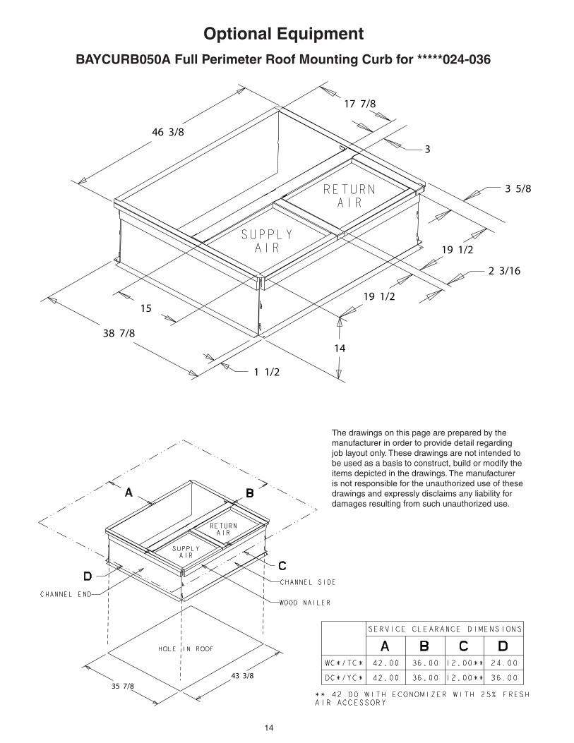
Optional EquipmentBAYCURB050A Full Perimeter Roof Mounting Curb for *****024-036
46 3/8
17 7/8
3
3 5/8
19 1/2
2 3/16
19 1/2
14
1 1/2
38 7/8
15
35 7/843 3/8
The drawings on this page are prepared by the manufacturer in order to provide detail regarding job layout only. These drawings are not intended to be used as a basis to construct, build or modify the items depicted in the drawings. The manufacturer is not responsible for the unauthorized use of these drawings and expressly disclaims any liability for damages resulting from such unauthorized use.

15
Optional EquipmentBAYCURB051A Full Perimeter Roof Mounting Curb for *****042-060
56 1/8
15 7/8
3
10 7/819 1/2
4 3/4
19 1/2
14
41 7/8
20
1 1/2
38 7/8 53 1/8
The drawings on this page are prepared by the manufacturer in order to provide detail regarding job layout only. These drawings are not intended to be used as a basis to construct, build or modify the items depicted in the drawings. The manufacturer is not responsible for the unauthorized use of these drawings and expressly disclaims any liability for damages resulting from such unauthorized use.

16
Optional Equipment
The drawings on this page are prepared by the manufacturer in order to provide detail regarding job layout only. These drawings are not intended to be used as a basis to construct, build or modify the items depicted in the drawings. The manufacturer is not respon-sible for the unauthorized use of these drawings and expressly disclaims any liability for damages resulting from such unauthorized use.
BAYFLTR101, 201B, 1" - 2" Filter Rack(Mounts in Filter/Coil Section)
BAYACCDOR1A & BAYACCDOR2A Hinged Filter Access DoorReplaces Filter/Coil Access Panel
Filter

17
BAYECON101,102A Down Discharge Economizer and Rain Hood(Mounts Over Horizontal Return Air Opening)
A
B
C D
E
BAYECON200,201A Horizontal Economizer and Rain Hood
Return DuctRoofcurb
Relief damper
Mist elimi-nator
Economizer rain hood
HVAC Unit
Outside air dampers
Return air damp-ers
Required filter kit, order separately
A
Optional Equipment
Economizer
Gaskets (2)
Rain HoodDuct
The drawings on this page are prepared by the manu-facturer in order to provide detail regarding job layout only. These drawings are not intended to be used as a basis to construct, build or modify the items depicted in the drawings. The manu-facturer is not responsible for the unauthorized use of these drawings and ex-pressly disclaims any liability for damages resulting from such unauthorized use.
Mixed Air Sensor
Economizer Unit Application Models A
BAYECON101A 4TC*,WC*,YC*,DC* *018-036 20.125"
BAYECON102A 4TC*,WC*,YC*, DC* *042-060 24.375"
Economizer A B C D E F
BAYECON200AA 22" 20" 16 7/8" 15 11/16 11 11/16 15
BAYECON201AA 26" 22 21/32" 19" 17 11/16 14 11/16 21-3/8

18
A
B
CD
FULLYOPEN
2/31/3
FULLYCLOSED
BAYDMPR101,102A, 25% Motorized Outside Air Damper(Mounts Over Horizontal Return AIr Opening)
BAYOSAH001, 002A, 25% Outside Air Damper(Replaces Filter/Coil Access Panel)
Optional Equipment
The drawings on this page are prepared by the manufacturer in order to provide detail regarding job layout only. These drawings are not intended to be used as a basis to construct, build or modify the items depicted in the drawings. The manufacturer is not responsible for the unauthorized use of these drawings and expressly disclaims any liability for dam-ages resulting from such unauthorized use.
D
C B
A
E
Manual Fresh Air Model Unit Application Models A B C D
BAYOSAH001
4YC,WC3018-0364TC*3018-036
4W/T/Y/DCY4024-0364W/Y/DCZ6036
22 7/16" 20 11/16" 12 3/8" 9 3/16"
BAYOSAH002
4YC,WC3042-0604TC*3042-060
4W/T/Y/DCY4042-0604W/Y/DCZ6048-060
25 3/16" 20 11/16" 12 3/8" 9 3/16"
Unit Application Models A B C D E
BAYDMPR101A
4YC,WC3018-0364TC3018-036
4W/T/Y/DCY4024-0364W/Y/DCZ6036
15 13/16" 11 13/16" 10 1/4" 11 1/2" 12 1/4"
BAYDMPR102A
4YC,WC3042-0604TC3042-060
4W/T/Y/DCY4042-0604W/Y/DCZ6048-060
18 3/16" 15 1/8" 10 1/4" 11 1/2" 12 1/4"

19
Dimensional Data
4DCY4024 through 4DCY4036 (1 of 3)
20
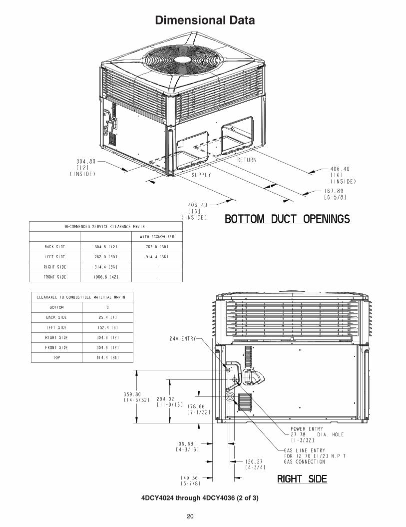
Dimensional Data
4DCY4024 through 4DCY4036 (2 of 3)

21
Dimensional Data
4DCY4024 through 4DCY4036 (3 of 3)

22
4DCY4042 through 4DCY4060 (1 of 3)
Dimensional Data

23
Dimensional Data
4DCY4042 through 4DCY4060 (2 of 3)

24
4DCY4042 through 4DCY4060 (3 of 3)
Dimensional Data

25
6200 Troup HighwayTyler, TX 75707-9010
The manufacturer has a policy of continuous product and product data improvement and it reserves the right
to change design and specifications without notice.
GeneralAll units shall be factory assembled, piped, internally wired and fully charged with refrigerant. All units shall be de-signed to operate at outdoor ambient temperatures as high as 115°F. Cooling capacities shall be rated in accordance with A.H.R.I. standards. The 4DCY4 heat-ing/cooling unit design is certified to UL Standards 1995 and ANSI 221.47/CSA 2.3, specifically for outdoor applications using natural gas or propane. All units shall be designed for outdoor rooftop or ground level installation. Unit casing is constructed of heavy gauge, galvanized steel and painted with a weather-resistant powder paint.
Shipped for horizontal application, convertible to downflow.
CasingsAll panels shall be heavy gauge steel, gasketed and insulated. Foil-faced insulation shall be in the heat exchanger section. Foil-faced insulation shall be in the evaporator section. Base pan shall be heavy gauge steel. WEATHERGUARD™ exterior corrosion resistant screws shall be used for added resistance to rust and corrosion.
ControlsRefrigeration cycle controls shall include condenser fan, evaporator fan and com-pressor contactors. Compressors shall be equipped with a combination internal winding thermostat/current overload. Internal high pressure relief shall also be provided.
Refrigeration SystemCompressors — The Climatuff® compressor features in-ternal over temperature and pressure pro-tector, total dipped hermetic motor. Other features include: centrifugal oil pump, and low vibration and noise. Evaporator Coil — Internally enhanced 3/8-inch OD seamless copper tubing me chani cally bonded to aluminum fins, factory pressure and leak tested at 250 to 300 psig. All units have TXV to control refrigeration flow.
Condenser Coil — The Spine Fin™ condenser coil shall be continuously wrapped, corrosion resistant all aluminum with minimum brazed joints. This coil is 3/8 inch OD seamless alumi-num tubing glued to a continuous alumi-num fin. Coils are lab tested to withstand 2,000 pounds of pressure per square inch. The outdoor coil provides low airflow resistance and efficient heat transfer. The coil is protected on all four sides by louvered panels.
Indoor Air Fan — Direct-drive, forward-curved, centrifugal wheel in a Composite Vortica® Blower housing. Motor shall have thermal overload protection. Perma-nently lubricated motor bearings. Motor/blower assembly isolated from unit with rubber mounts.
Condenser Fan — Direct-drive, draw through propeller type. Weather-proofed permanent split capacitor fan motor shall have built-in thermal overload and perma-nently lubricated motor bearings.
Low Ambient — Standard refrigerant system operation down to 55°F. Low am-bient accessory required for operation to 0°F ambient condition.
Gas-Fired Heating System — Models shall provide completely assembled, wired and piped gas fired heating systems within unit. Threaded gas connection on the unit.
Electronic Ignition System — Main burner is lit each time thermostat calls for gas heat. Flame sensor proves flame and keeps the main burners on. Should a loss of flame occur, the main valve closes and the spark recurs within 0.8 second. When thermostat is satisfied, main burner is extinguished.
Forced Combustion Blower — Insures flame stability under varying wind condi-tions. Gives higher combustion efficiency and location flexibility.
Heat Exchanger — stainless steel tubes. Free floating design.
Burners — Stainless steel. Multi-port inshot.
Accessories (U.S. Domestic Models)Roof Curb — The roof curb shall be designed to mate with the unit and provide support and complete weather-tight installation when properly installed. Curb shall ship knocked down for field assembly, and include wood nailer strips.
Modulating Economizer — This accessory shall be field installed and be composed of the following items: 0-100% fresh air damper, damper drive motor fixed dry bulb enthalpy control, and low voltage polarized plug for electrical connections. Solid state enthalpy or differential enthalpy control is optional. Economizer operations shall be controlled by the preset position of the enthalpy control. A barometic relief damper shall be standard with the economizer and provide a pressure operated damper that shall be gravity closing and prohibit entrance of outside air on equipment “off” cycle.
Manual Fresh Air HoodManual outside air provides a fixed out-side air quantity from 0 to 25 percent. Includes hood and birdscreen.
Low Ambient ControlControl allows cycling of compressor under low ambient cooling conditions. Required for cooling operation to 0°F.
Propane GasConversion Kit — For conversion from natural gas to LP gas.
Mechanical Specifications