22. electromagnetic induction and ......2019/01/07 · 22. electromagnetic induction and...
TRANSCRIPT
22. E L E C T R O M A G N E T I C I N D U C T I O N A N D E L E C T R O M A G N E T I C W AV E S
B
Ads
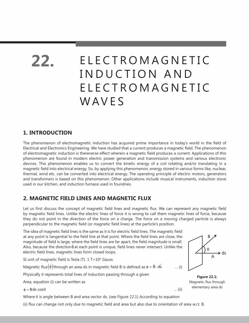
Figure 22.1: Magnetic flux through
elementary area ds
1. INTRODUCTION
The phenomenon of electromagnetic induction has acquired prime importance in today’s world in the field of Electrical and Electronics Engineering. We have studied that a current produces a magnetic field. The phenomenon of electromagnetic induction is thereverse effect wherein a magnetic field produces a current. Applications of this phenomenon are found in modern electric power generation and transmission systems and various electronic devices. This phenomenon enables us to convert the kinetic energy of a coil rotating and/or translating in a magnetic field into electrical energy. So, by applying this phenomenon, energy stored in various forms like, nuclear, thermal, wind etc. can be converted into electrical energy. The operating principle of electric motors, generators and transformers is based on this phenomenon. Other applications include musical instruments, induction stove used in our kitchen, and induction furnace used in foundries.
2. MAGNETIC FIELD LINES AND MAGNETIC FLUX
Let us first discuss the concept of magnetic field lines and magnetic flux. We can represent any magnetic field by magnetic field lines. Unlike the electric lines of force it is wrong to call them magnetic lines of force, because they do not point in the direction of the force on a charge. The force on a moving charged particle is always perpendicular to the magnetic field (or magnetic field lines) at the particle’s position.
The idea of magnetic field lines is the same as it is for electric field lines. The magnetic field at any point is tangential to the field line at that point. Where the field lines are close, the magnitude of field is large, where the field lines are far apart, the field magnitude is small. Also, because the directionB
at each point is unique, field lines never intersect. Unlike the
electric field lines, magnetic lines form closed loops.
SI unit of magnetic field is Tesla (T). 1 T=104 Gauss.
Magnetic flux ( )φ through an area ds in magnetic field B is defined as B dsφ = ⋅
… (i)
Physically it represents total lines of induction passing through a given
Area, equation (i) can be written as
Bds cosφ = θ … (ii)
Where θ is angle between B and area vector ds. (see Figure 22.1) According to equation
(ii) flux can change not only due to magnetic field and area but also due to orientation of area w.r.t. B.
22.2 | Electromagnetic Induction and Electromagnetic Waves
Dimensional formula of flux is 22 1ML T A− −
Note down the following points regarding the magnetic flux:
(a) Magnetic flux is a scalar quantity (dot product of two vector quantities is scalar quantity)
(b) The SI unit of magnetic flux is tesla-meter2 (1T-m2). This unit is called weber (1 Wb)
1Wb=1Tm2=Nm/A
Thus, unit of magnetic field is also weber/m2(1Wb/m2), or 1 T=1Wb/m2
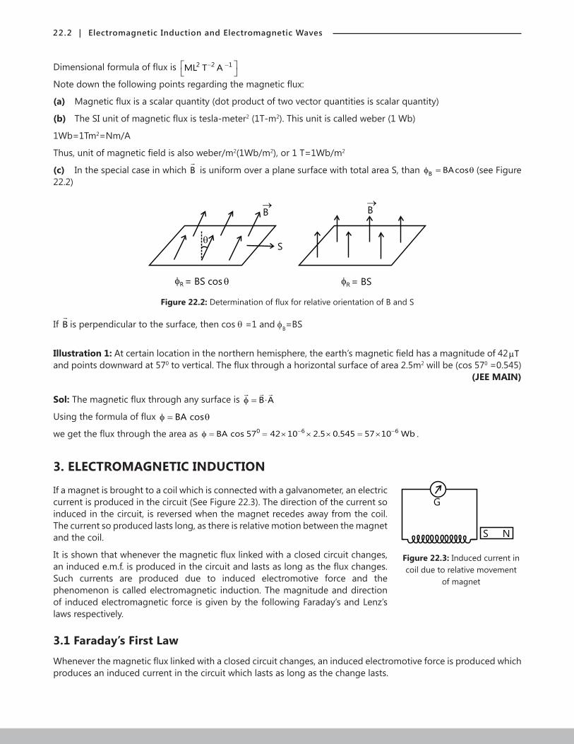
(c) In the special case in which B
is uniform over a plane surface with total area S, than B BAcosφ = θ (see Figure 22.2)
B
S
= BS cos R
B
= BSR
Figure 22.2: Determination of flux for relative orientation of B and S
If B
is perpendicular to the surface, then cos θ =1 and fB=BS
Illustration 1: At certain location in the northern hemisphere, the earth’s magnetic field has a magnitude of 42 Tµand points downward at 570 to vertical. The flux through a horizontal surface of area 2.5m2 will be (cos 570 =0.545) (JEE MAIN)
Sol: The magnetic flux through any surface is B • Aφ = .B • Aφ =
Using the formula of flux BA cosφ = θ
we get the flux through the area as 0 6 6BA cos 57 42 10 2.5 0.545 57 10 Wb− −φ = = × × × = × .
3. ELECTROMAGNETIC INDUCTION
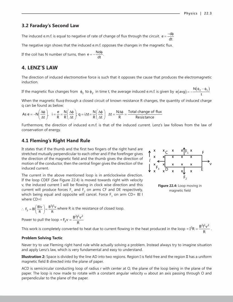
If a magnet is brought to a coil which is connected with a galvanometer, an electricG
S N
Figure 22.3: Induced current in coil due to relative movement
of magnet
current is produced in the circuit (See Figure 22.3). The direction of the current so induced in the circuit, is reversed when the magnet recedes away from the coil. The current so produced lasts long, as there is relative motion between the magnet and the coil.
It is shown that whenever the magnetic flux linked with a closed circuit changes, an induced e.m.f. is produced in the circuit and lasts as long as the flux changes. Such currents are produced due to induced electromotive force and the phenomenon is called electromagnetic induction. The magnitude and direction of induced electromagnetic force is given by the following Faraday’s and Lenz’s laws respectively.
3.1 Faraday’s First Law
Whenever the magnetic flux linked with a closed circuit changes, an induced electromotive force is produced which produces an induced current in the circuit which lasts as long as the change lasts.
Physics | 22.3
3.2 Faraday’s Second Law
The induced e.m.f. is equal to negative of rate of change of flux through the circuit. dedt
− φ=
The negative sign shows that the induced e.m.f. opposes the changes in the magnetic flux.
If the coil has N number of turns, then Nde .dt
φ= −
4. LENZ’S LAW
The direction of induced electromotive force is such that it opposes the cause that produces the electromagnetic induction.
If the magnetic flux changes from 1 2toφ φ in time t, the average induced e.m.f. is given by ( ) ( )2 1Ne avg
t
φ − φ= −
When the magnetic flux φ through a closed circuit of known resistance R changes, the quantity of induced charge q can be found as below:
Total change of fluxe N N NAs e N , i ; q i t tt R R t R t R Resistance
∆φ ∆φ ∆φ ∆φ= − = = = ∆ = ∆ = = ∆ ∆ ∆
Furthermore, the direction of induced e.m.f. is that of the induced current. Lenz’s law follows from the law of conservation of energy.
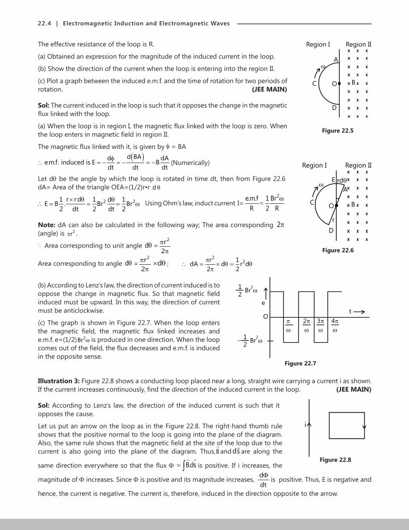
4.1 Fleming’s Right Hand Rule
It states that if the thumb and the first two fingers of the right hand are
Figure 22.4: Loop moving in magnetic field
C
D
F1 F
v
EF
3
F2
lstretched mutually perpendicular to each other and if the forefinger gives the direction of the magnetic field and the thumb gives the direction of motion of the conductor, then the central finger gives the direction of the induced current.
The current in the above mentioned loop is in anticlockwise direction. If the loop CDEF (See Figure 22.4) is moved towards right with velocity v, the induced current I will be flowing in clock wise direction and this current will produce forces F1 and F2 on arms CF and DE respectively, which being equal and opposite will cancel. Force F3 on arm CD= BI l where CD=l
2 2
3Blv B l vF BlR R
∴ = =
where R is the resistance of closed loop.
Power to pull the loop =2 2 2
3B l vF v
R=
This work is completely converted to heat due to current flowing in the heat produced in the loop =2 2 2
2 B l vI RR
= .
Problem Solving Tactic
Never try to use Fleming right hand rule while actually solving a problem. Instead always try to imagine situation and apply Lenz’s law, which is very fundamental and easy to understand.
Illustration 2: Space is divided by the line AD into two regions. Region I is field free and the region II has a uniform magnetic field B directed into the plane of paper.
ACD is semicircular conducting loop of radius r with center at O, the plane of the loop being in the plane of the paper. The loop is now made to rotate with a constant angular velocity w about an axis passing through O and perpendicular to the plane of the paper.
22.4 | Electromagnetic Induction and Electromagnetic Waves
The effective resistance of the loop is R.
(a) Obtained an expression for the magnitude of the induced current in the loop.
B
Region I Region II
O
D
C
A
Figure 22.5
(b) Show the direction of the current when the loop is entering into the region II.
(c) Plot a graph between the induced e.m.f. and the time of rotation for two periods of rotation. (JEE MAIN)
Sol: The current induced in the loop is such that it opposes the change in the magnetic flux linked with the loop.
(a) When the loop is in region I, the magnetic flux linked with the loop is zero. When the loop enters in magnetic field in region II.
The magnetic flux linked with it, is given by f = BA( )
e.m.f. induced id BAd dAE B
dt t dts
dφ
= − = − = −∴ (Numerically)
Figure 22.6
B
Region I Region II
O
D
C
E
r
rdA
Let dθ be the angle by which the loop is rotated in time dt, then from Figure 22.6 dA= Area of the triangle OEA=(1/2)r•r d θ
2 2r rd1 1 d 1E B . Br Br2 dt 2 dt 2
× θ θ∴ = = = ω Using Ohm’s law, induct current I=
2e.m.f 1 BrR 2 R
ω=
Note: dA can also be calculated in the following way; The area corresponding 2π(angle) is 2rπ .
∴ Area corresponding to unit angle dθ =2r
2π
π
Area corresponding to angle dθ =2r
2π
πd× θ ;
22r 1dA d r d
2 2π
∴ = × θ = θπ
(b) According to Lenz’s law, the direction of current induced is to
Figure 22.7
e
tO
2
3
4
1
2Br
2
1
2Br
2-
oppose the change in magnetic flux. So that magnetic field induced must be upward. In this way, the direction of current must be anticlockwise.
(c) The graph is shown in Figure 22.7. When the loop enters the magnetic field, the magnetic flux linked increases and e.m.f. e=(1/2) 2Br ω is produced in one direction. When the loop comes out of the field, the flux decreases and e.m.f. is induced in the opposite sense.
Illustration 3: Figure 22.8 shows a conducting loop placed near a long, straight wire carrying a current i as shown. If the current increases continuously, find the direction of the induced current in the loop. (JEE MAIN)
Sol: According to Lenz’s law, the direction of the induced current is such that it
Figure 22.8
iopposes the cause.
Let us put an arrow on the loop as in the Figure 22.8. The right-hand thumb rule shows that the positive normal to the loop is going into the plane of the diagram. Also, the same rule shows that the magnetic field at the site of the loop due to the current is also going into the plane of the diagram. Thus,B
and ds
are along the
same direction everywhere so that the flux Φ B.dsΦ = ∫
is positive. If i increases, the
magnitude of Φ increases. Since Φ is positive and its magnitude increases, ddtΦ
is positive. Thus, E is negative and
hence, the current is negative. The current is, therefore, induced in the direction opposite to the arrow.
Physics | 22.5
5. THE ORIGIN OF INDUCED E.M.F.
E.M.F. is defined as the external mechanism by which work is done per unit charge to maintain the electric field in the wire so as to establish electric current in a conducting wire.
The flux B.ds∫
can be changed by
(a) Keeping the magnetic field constant as time passes and moving whole or part of the loop
(b) Keeping the loop at rest changing the magnetic field
(c) Combination of (a) and (b), that is, by moving the loop (partly or wholly) as well as by changing the field.
The mechanism by which e.m.f. is produced is different in the two basic processes (a) and (b). We now study them under the headings motional e.m.f. and induced electric field.
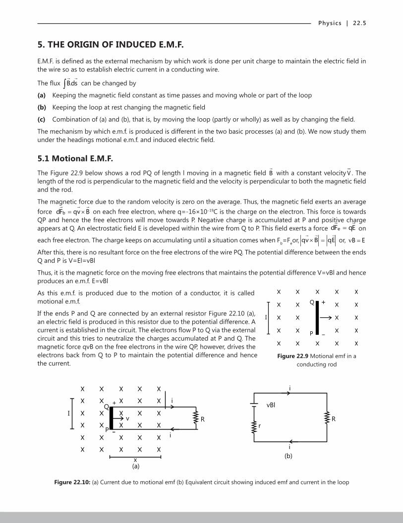
5.1 Motional E.M.F.
The Figure 22.9 below shows a rod PQ of length l moving in a magnetic field B
with a constant velocity V
. The length of the rod is perpendicular to the magnetic field and the velocity is perpendicular to both the magnetic field and the rod.
The magnetic force due to the random velocity is zero on the average. Thus, the magnetic field exerts an average force bdF qv B= ×
on each free electron, where q=-16×10-19C is the charge on the electron. This force is towards
QP and hence the free electrons will move towards P. Negative charge is accumulated at P and positive charge appears at Q. An electrostatic field E is developed within the wire from Q to P. This field exerts a force edF qE=
on
each free electron. The charge keeps on accumulating until a situation comes when Fb=Feor, qv B qE× =
or, B Eν =
After this, there is no resultant force on the free electrons of the wire PQ. The potential difference between the ends Q and P is V=El=vBl
Thus, it is the magnetic force on the moving free electrons that maintains the potential difference V=vBl and hence produces an e.m.f. E=vBl
As this e.m.f. is produced due to the motion of a conductor, it is called
Figure 22.9 Motional emf in a conducting rod
+
P -
Q
I
motional e.m.f.
If the ends P and Q are connected by an external resistor Figure 22.10 (a), an electric field is produced in this resistor due to the potential difference. A current is established in the circuit. The electrons flow P to Q via the external circuit and this tries to neutralize the charges accumulated at P and Q. The magnetic force qvB on the free electrons in the wire QP, however, drives the electrons back from Q to P to maintain the potential difference and hence the current.
I
x
(a)
R
i
i
Q
P
+
-
v
vBl
r
R
i
i
(b)
Figure 22.10: (a) Current due to motional emf (b) Equivalent circuit showing induced emf and current in the loop
22.6 | Electromagnetic Induction and Electromagnetic Waves
Thus, we can replace the moving rod QP by battery of e.m.f. Blν with the positive terminal at Q and the negative terminal at P. The resistance r of the rod QP may be treated as the internal resistance of the battery. Figure 22.10 (b) shows the equivalent circuit.
The current is Bli
R rν
=+
in the clockwise direction (induced current).
We can also find the induced e.m.f. and the induced current in the loop in Fig.22.10 (a) from Faraday’s law of electromagnetic induction. If x be the length of the circuit in the magnetic field at time t, the magnetic flux through the area bounded by the loop is Blx.Φ =
The magnitude of the induced e.m.f. is d dxBldt dtΦ
= =E Bl.= ν
The current isBli
R rν
=+
. The direction of the current can be worked out from Lenz’s law.
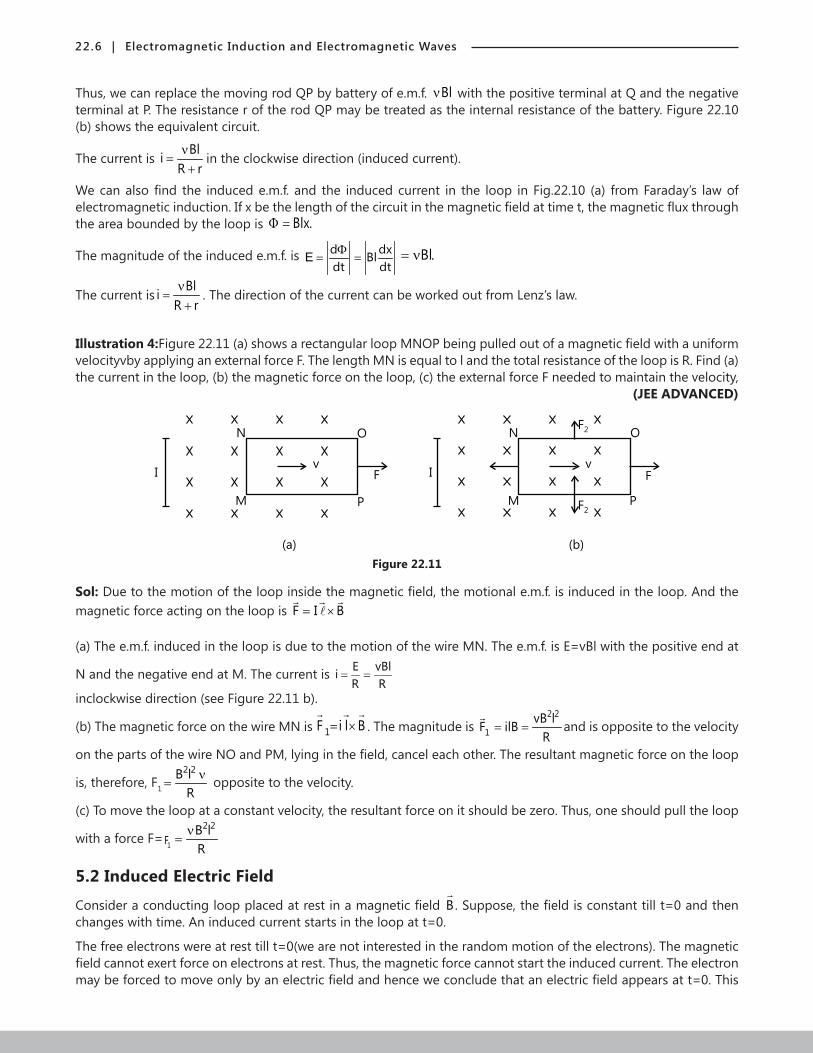
Illustration 4:Figure 22.11 (a) shows a rectangular loop MNOP being pulled out of a magnetic field with a uniform velocityvby applying an external force F. The length MN is equal to l and the total resistance of the loop is R. Find (a) the current in the loop, (b) the magnetic force on the loop, (c) the external force F needed to maintain the velocity, (JEE ADVANCED)
I
N
M
v
O
F
P
I
N
M
F2
F2
v
O
P
F
(a) (b)
Figure 22.11
Sol: Due to the motion of the loop inside the magnetic field, the motional e.m.f. is induced in the loop. And the magnetic force acting on the loop is F I B= ×
(a) The e.m.f. induced in the loop is due to the motion of the wire MN. The e.m.f. is E=vBl with the positive end at
N and the negative end at M. The current is E vBliR R
= =
inclockwise direction (see Figure 22.11 b).
(b) The magnetic force on the wire MN is 1F i l B= ×
. The magnitude is 2 2
1vB lF ilB
R= =
and is opposite to the velocity
on the parts of the wire NO and PM, lying in the field, cancel each other. The resultant magnetic force on the loop
is, therefore, F1
2 2B lR
ν= opposite to the velocity.
(c) To move the loop at a constant velocity, the resultant force on it should be zero. Thus, one should pull the loop
with a force F= 1F2 2B l
Rν
=
5.2 Induced Electric Field
Consider a conducting loop placed at rest in a magnetic field B
. Suppose, the field is constant till t=0 and then changes with time. An induced current starts in the loop at t=0.
The free electrons were at rest till t=0(we are not interested in the random motion of the electrons). The magnetic field cannot exert force on electrons at rest. Thus, the magnetic force cannot start the induced current. The electron may be forced to move only by an electric field and hence we conclude that an electric field appears at t=0. This
Physics | 22.7
electric field is produced by the changing magnetic field and not by charged particles according to the Coulomb’s law or the Gauss’s law. The electric field produced by the changing magnetic field is non-electrostatic and non-conservative in nature. We cannot define a potential corresponding to this field. We call it induced electric field. The lines of induced electric field are curves. There are no starting and terminating points of the lines.
If E
be the induced electric field, the force on a charge q placed in the field is qE
. The work done per unit charge as the charge moves through dl
is E dl⋅
.
The E.M.F. developed in the loop is,
E.dl.=ε ∫
Using Faraday’s Law of Induction,
d d or E.dldt dtΦ Φ
= − = −ε ∫
The presence of a conducting loop is not necessary to have an induced electric field. As long as B
keeps changing,
the induced electric field is present. If a loop is there, the free electrons start drifting and consequently an induced current results.
Note: Induced electric field is not similar to electrostatic field. The biggest difference is that electrostatic field is conservative while the other one is not.
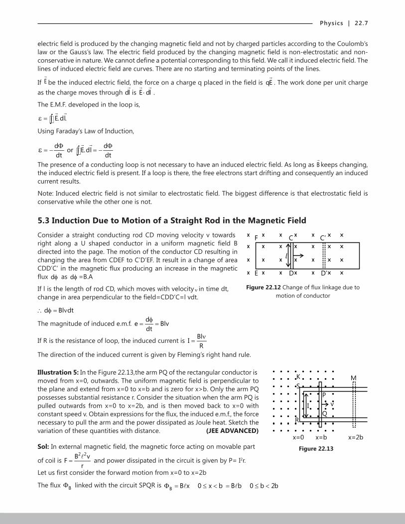
5.3 Induction Due to Motion of a Straight Rod in the Magnetic Field
Consider a straight conducting rod CD moving velocity v towards F C C’
E D D’
l
Figure 22.12 Change of flux linkage due to motion of conductor
right along a U shaped conductor in a uniform magnetic field B directed into the page. The motion of the conductor CD resulting in changing the area from CDEF to C’D’EF. It result in a change of area CDD’C’ in the magnetic flux producing an increase in the magnetic flux dφ as dφ =B.A
If l is the length of rod CD, which moves with velocity ν in time dt, change in area perpendicular to the field=CDD’C=l vdt.
d Bl dt∴ φ = ν
The magnitude of induced e.m.f. de Blvdt
φ= =
If R is the resistance of loop, the induced current is BlIRν
=
The direction of the induced current is given by Fleming’s right hand rule.
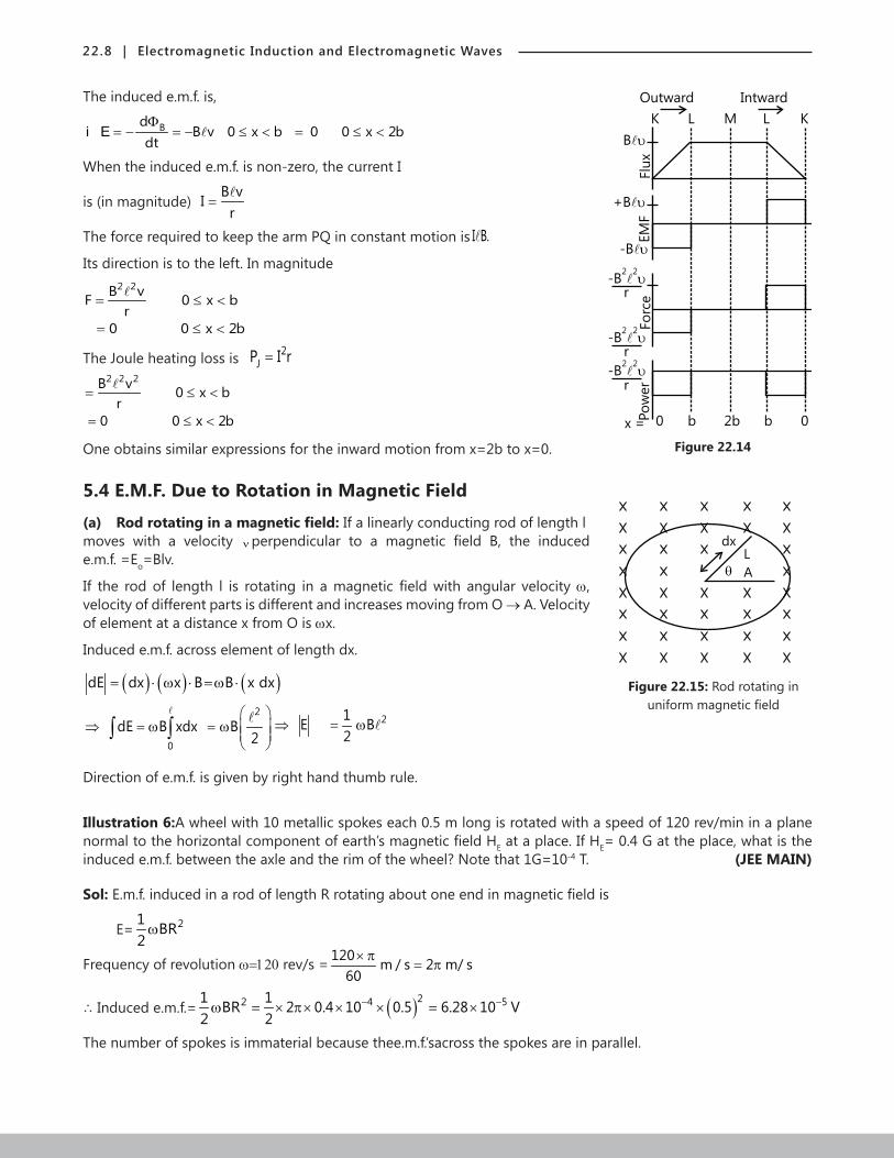
Illustration 5: In the Figure 22.13,the arm PQ of the rectangular conductor is
Figure 22.13
M
x=0 x=b x=2b
K
S
RQ
P
vI
moved from x=0, outwards. The uniform magnetic field is perpendicular to the plane and extend from x=0 to x=b and is zero for x>b. Only the arm PQ possesses substantial resistance r. Consider the situation when the arm PQ is pulled outwards from x=0 to x=2b, and is then moved back to x=0 with constant speed v. Obtain expressions for the flux, the induced e.m.f., the force necessary to pull the arm and the power dissipated as Joule heat. Sketch the variation of these quantities with distance. (JEE ADVANCED)
Sol: In external magnetic field, the magnetic force acting on movable part
of coil is 2 2B vFr
= and power dissipated in the circuit is given by P= I2r.
Let us first consider the forward motion from x=0 to x=2b
The flux BΦ linked with the circuit SPQR is B B x 0 x b B b 0 b 2bΦ = ≤ < = ≤ <
22.8 | Electromagnetic Induction and Electromagnetic Waves
The induced e.m.f. is,
Figure 22.14
Outward Intward
K L LM K
0 b 2b b 0
B
Flu
x
+B
EM
F
-B
-B2 2 r
-B2 2 r
-B2 2 r
Fo
rce
Po
wer
x =
BdB v 0 x b 0 0 x 2b
dtΦ
= − = − ≤ < = ≤ <i E
When the induced e.m.f. is non-zero, the current I
is (in magnitude) B vI
r=
The force required to keep the arm PQ in constant motion is I B.
Its direction is to the left. In magnitude2 2B vF 0 x br
0 0 x 2b
= ≤ <
= ≤ <
The Joule heating loss is 2JP I r=
2 2 2B v 0 x br
0 0 x 2b
= ≤ <
= ≤ <
One obtains similar expressions for the inward motion from x=2b to x=0.
5.4 E.M.F. Due to Rotation in Magnetic Field
(a) Rodrotatinginamagneticfield:If a linearly conducting rod of length l
Figure 22.15: Rod rotating in uniform magnetic field
dx
L
A
moves with a velocity ν perpendicular to a magnetic field B, the induced e.m.f. =Eo=Blv.
If the rod of length l is rotating in a magnetic field with angular velocity w, velocity of different parts is different and increases moving from O → A. Velocity of element at a distance x from O is wx.
Induced e.m.f. across element of length dx.
( ) ( ) ( )dE dx x B B x dx= ⋅ ω ⋅ =ω ⋅
2
0
2
dE B xdx B2
1E B2
⇒ = ω = ω
⇒ = ω
∫ ∫
2
0
2
dE B xdx B2
1E B2
⇒ = ω = ω
⇒ = ω
∫ ∫
Direction of e.m.f. is given by right hand thumb rule.
Illustration 6:A wheel with 10 metallic spokes each 0.5 m long is rotated with a speed of 120 rev/min in a plane normal to the horizontal component of earth’s magnetic field HE at a place. If HE= 0.4 G at the place, what is the induced e.m.f. between the axle and the rim of the wheel? Note that 1G=10-4 T. (JEE MAIN)
Sol: E.m.f. induced in a rod of length R rotating about one end in magnetic field is
E= 21 BR2
ω
Frequency of revolution w=120 rev/s = 120 m / s 2 m/ s60
× π= π
∴ Induced e.m.f.= 21 BR2
ω ( )24 51 2 0.4 10 0.5 6.28 10 V2
− −= × π × × × = ×
The number of spokes is immaterial because thee.m.f.’sacross the spokes are in parallel.
Physics | 22.9
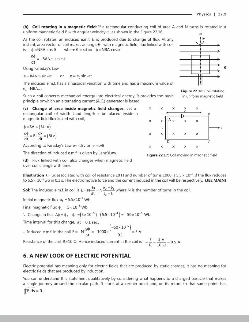
(b) Coil rotating inamagneticfield: If a rectangular conducting coil of area A and N turns is rotated in a uniform magnetic field B with angular velocity w, as shown in the Figure 22.16.
As the coil rotates, an induced e.m.f. E, is produced due to change of flux. At any
Figure 22.16: Coil rotating in uniform magnetic field
B
instant, area vector of coil makes an angle θ with magnetic field, flux linked with coil is NBA cos where t NBA cos t
d BAN sin tdt
φ = θ θ = ω ⇒ φ = ωφ
= − ω ω
Using Faraday’s Law
e BAN sin t= ω ω or 0e e sin t= ω
The induced e.m.f. has a sinusoidal variation with time and has a maximum value of e0 =NBA ω .
Such a coil converts mechanical energy into electrical energy. It provides the basic principle onwhich an alternating current (A.C.) generator is based.
(c) Change of area insidemagnetic field changes: Let a
A
L
x
D C
B
v
Figure 22.17: Coil moving in magnetic field
rectangular coil of width Land length x be placed inside a magnetic field flux linked with coil,
( )( )
BA BL x
d dxBL BLvdt dt
φ = = ⋅
φ= =
According to Faraday’s Law e=-LBv or |e|=LvB
The direction of induced e.m.f. is given by Lenz’sLaw.
(d) Flux linked with coil also changes when magnetic field over coil change with time.
Illustration 7:Flux associated with coil of resistance 10 Ω and number of turns 1000 is 5.5 × 10⁻⁴. If the flux reduces to 5.5 × 10⁻⁵ wb in 0.1 s. The electromotive force and the current induced in the coil will be respectively. (JEE MAIN)
Sol: The induced e.m.f. in coil is 2 1
2 1
dE N Ndt t t
φ − φφ= =
−where N is the number of turns in the coil.
Initial magnetic flux 41 5.5 10−φ = × Wb.
Final magnetic flux 52 5 10−φ = × Wb.
∴ Change in flux ( ) ( )5 4 52 1 5 10 5.5 10 50 10 Wb− − −∆φ = φ − φ = × − × = − ×
Time interval for this change, t 0.1 sec.∆ =
∴ Induced e.m.f. in the coil ( )550 10
E N 1000 5 Vt 0.1
−− ×∆Φ= − = − × =
∆
Resistance of the coil, R=10 Ω. Hence induced current in the coil is 5 VEi 0.5 AR 10
= = =Ω
6. A NEW LOOK OF ELECTRIC POTENTIAL
Electric potential has meaning only for electric fields that are produced by static charges; it has no meaning for electric fields that are produced by induction.
You can understand this statement qualitatively by considering what happens to a charged particle that makes a single journey around the circular path. It starts at a certain point and, on its return to that same point, has
E.ds 0.=∫
22.10 | Electromagnetic Induction and Electromagnetic Waves
However, when a changing magnetic flux is present, this integral is not zero but is -dΦB/d.Thus, assigning electric potential to an induced electric field leads us to a contradiction. We must conclude that electric potential has no meaning for electric fields associated with induction.
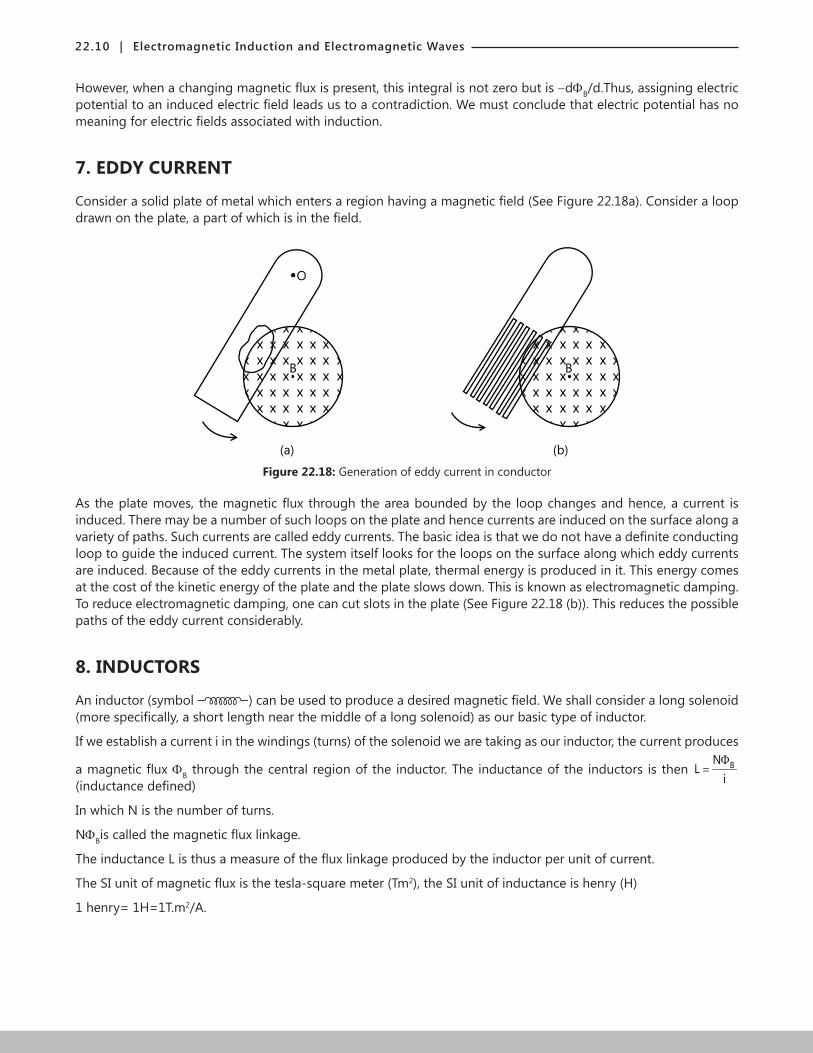
7. EDDY CURRENT
Consider a solid plate of metal which enters a region having a magnetic field (See Figure 22.18a). Consider a loop drawn on the plate, a part of which is in the field.
B
O
(a) (b)
B
Figure 22.18: Generation of eddy current in conductor
As the plate moves, the magnetic flux through the area bounded by the loop changes and hence, a current is induced. There may be a number of such loops on the plate and hence currents are induced on the surface along a variety of paths. Such currents are called eddy currents. The basic idea is that we do not have a definite conducting loop to guide the induced current. The system itself looks for the loops on the surface along which eddy currents are induced. Because of the eddy currents in the metal plate, thermal energy is produced in it. This energy comes at the cost of the kinetic energy of the plate and the plate slows down. This is known as electromagnetic damping. To reduce electromagnetic damping, one can cut slots in the plate (See Figure 22.18 (b)). This reduces the possible paths of the eddy current considerably.
8. INDUCTORS
An inductor (symbol ) can be used to produce a desired magnetic field. We shall consider a long solenoid (more specifically, a short length near the middle of a long solenoid) as our basic type of inductor.
If we establish a current i in the windings (turns) of the solenoid we are taking as our inductor, the current produces
a magnetic flux ΦB through the central region of the inductor. The inductance of the inductors is then BNL
iΦ
= (inductance defined)
In which N is the number of turns.
NΦBis called the magnetic flux linkage.
The inductance L is thus a measure of the flux linkage produced by the inductor per unit of current.
The SI unit of magnetic flux is the tesla-square meter (Tm2), the SI unit of inductance is henry (H)
1 henry= 1H=1T.m2/A.

Physics | 22.11
8.1 Potential Difference acrossan Inductor
We can find the direction of self-induced e.m.f. across an inductor from Lenz’s law.
i (constant)
a b
I (increasing)
a b
+ -
dl
dt=0
e=0
Vab=0
e
dl
dt> 0
Vab=0
dl
dt>0
Vab<0
(a) (b) ( )c
i (decreasing)
a b
+ -
e
Figure 22.19: Variation of current in inductor coil
8.2 Self Induction
When the current is increased or reduced in the coil, it results in a change of magnetic flux due to which an e.m.f. is induced in the coil, andthis is called self-induced e.m.f. due to the phenomenon of self-induction. If a current I is flowing in a coil, a magnetic flux φ is linked to the coil which is directly proportional to the current ∴ φ ∝ I or φ =LI
Where L is a constant of proportionality and is called self-inductance of the coil or simply inductance of the coil.
∴ E.M.F. induced in the coil, d dIE Ldt dt
φ= − = −
The self-inductance of a coil is the e.m.f. induced in it when the rate change of current is unity. The unit of inductance is Henry (H). One Henry is defined as the inductance of a coil in which an e.m.f. of 1 volt is produced, when the current in the coil is changing at the rate of one ampere per second (A/s). If a solenoid has n number of turns per meter and l is its length with total number of turns N=n and area of cross section A, its inductance L is
22 0
0N A
L n Aµ
= µ =
The SI unit of self-inductance L is weber-1 or volt second ampere-1 (Vs/A). It is given the special name Henry and is
abbreviated as H. If we have a coil or a solenoid of N turns, the flux through each turn is B ds⋅∫
. If this flux changes,
an e.m.f. is induced in each turn. The net e.m.f. induced between the ends of the coil is the sum of all these.Thus, dE N B.dsdt
= − ∫
One can compare this with the previous equation to get the inductance.
Illustration 8: The inductor shown in Figure 22.20 has inductance of 0.54 H and carries
a b
L
i
Figure 22.20
a current in the direction shown that is decreasing at a uniform rate di 0.03 A / s.dt
= −
(a) Find the self-induced e.m.f.
(b) Which end of the inductor,a or b, is at a higher potential? (JEE MAIN)
Sol: The e.m.f. induced in an inductordue to self-inductance opposesthe change in current in it. As the current decreases, the induced e.m.f. tries to increase the current, thus a will be at higher potential.
(a) Self-inducede.m.f. ( )( ) 2dIE L 0.54 0.03 V 1.62 10 Vdt
−= − = − − = ×
(b) Potential difference between two ends of inductor is 2ba
dIV L 1.62 10 Vdt
−= = − ×
Since Vba (Vb-Va) is negative. It implies that Va>Vb or a is at higher potential.
22.12 | Electromagnetic Induction and Electromagnetic Waves
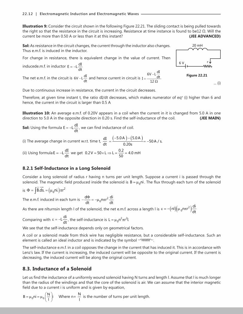
Illustration 9: Consider the circuit shown in the following Figure 22.21. The sliding contact is being pulled towards the right so that the resistance in the circuit is increasing. Resistance at time instance is found to be12 Ω. Will the current be more than 0.50 A or less than it at this instant? (JEE ADVANCED)
Sol: As resistance in the circuit changes, the current through the inductor also changes.
Figure 22.21
20 mH
6 V r
Thus e.m.f. is induced in the inductor.
For change in resistance, there is equivalent change in the value of current. Then
inducede.m.f. in inductor dIE Ldt
= −
The net e.m.f. in the circuit is dI6V Ldt
− and hence current in circuit is dI6V LdtI
12
−=
Ω
... (i)
Due to continuous increase in resistance, the current in the circuit decreases.
Therefore, at given time instant t, the ratio dI/dt decreases, which makes numerator of eqn (i) higher than 6 and hence, the current in the circuit is larger than 0.5 A
Illustration 10: An average e.m.f. of 0.20V appears in a coil when the current in it is changed from 5.0 A in one direction to 5.0 A in the opposite direction in 0.20 s. Find the self-inductance of the coil. (JEE MAIN)
Sol: Using the formula dIE Ldt
= − , we can find inductance of coil.
(i) The average change in current w.r.t. time t, dIdt
( ) ( )5.0A 5.0Adi 50A / s.
dt 0.20s
− −= = −
(ii) Using formula dIE Ldt
= − we get 0.20.2V 50 L L 4.0 mH50
= × ⇒ = =
8.2.1 Self-Inductance in a Long Solenoid
Consider a long solenoid of radius r having n turns per unit length. Suppose a current i is passed through the solenoid. The magnetic field produced inside the solenoid is 0B ni= µ . The flux through each turn of the solenoid
is ( ) 20B.ds. ni. rΦ = = µ π∫
The e.m.f. induced in each turn is 20
d din rdt dtΦ
− = −µ π
As there are nlturnsin length l of the solenoid, the net e.m.f. across a length l is ( )( )20
dinl n rdt
ε = − µ π
Comparing with diLdt
ε = − , the self-inductance is 2 20L n r l.= µ π
We see that the self-inductance depends only on geometrical factors.
A coil or a solenoid made from thick wire has negligible resistance, but a considerable self-inductance. Such an element is called an ideal inductor and is indicated by the symbol .
The self-inductance e.m.f. in a coil opposes the change in the current that has induced it. This is in accordance with Lenz’s law. If the current is increasing, the induced current will be opposite to the original current. If the current is decreasing, the induced current will be along the original current.
8.3. Inductance of a Solenoid
Let us find the inductance of a uniformly wound solenoid having N turns and length l. Assume that l is much longer than the radius of the windings and that the core of the solenoid is air. We can assume that the interior magnetic field due to a current i is uniform and is given by equation,
0 0NB ni il
= µ = µ
Where n= N
l is the number of turns per unit length.
Physics | 22.13
The magnetic flux through each turn is, B 0NSBS i
lφ = = µ . Here, S is the cross-sectional area of the solenoid.
Now, 2
0 0B NSi N SN NLi i l l
µ µφ= = =
20N S
Ll
µ∴ =
This result shows that L depends on dimensions (S,l) and is proportional to the square of the number of turns. L∝N2
Because N=nl, we can also express the result in the form,
( )22 2 2
0 0 0 0
nlL s n Sl n V or L n V
l= µ = µ = µ = µ
Here, V=Sl is the volume of the solenoid.
Illustration 11: Two inductors L1 and L2 are placed sufficientlyapart. Find out equivalent inductance when they are connected (a) in series (b) in parallel. (JEE MAIN)
Sol: For inductors, when they are connected in series, the inductance of the combination should increase, while for parallel connection, the inductance of combination should decrease
(i) In series the induced current i flows in the both the inductors and the total magnetic-flux linked with them will be equal to the sum of the fluxes linked with them individually, that is, Φ=L1i+L2i
If the equivalent inductance be L. then Φ=Li ∴ Li=L1+L2 or L=L1+L2
(ii) In parallel, let the induced currents in the two coils be i1 and i2 Then the total induced current is I= I1 + I2
1 2dI dIdIdt dt dt
∴ = +
In parallel, the induced e.m.f. across each coil will be the same. Hence, 1 21 2
dI dIE L L
dt dt= − = −
If the equivalent inductance be L, then diE Ldt
= −
1 2
1 2
dI dIE dI E EL dt dt dt L L
∴ = − = − + = +
or 1 2
1 2 1 2
L L1 1 1 or LL L L L L
= + =+
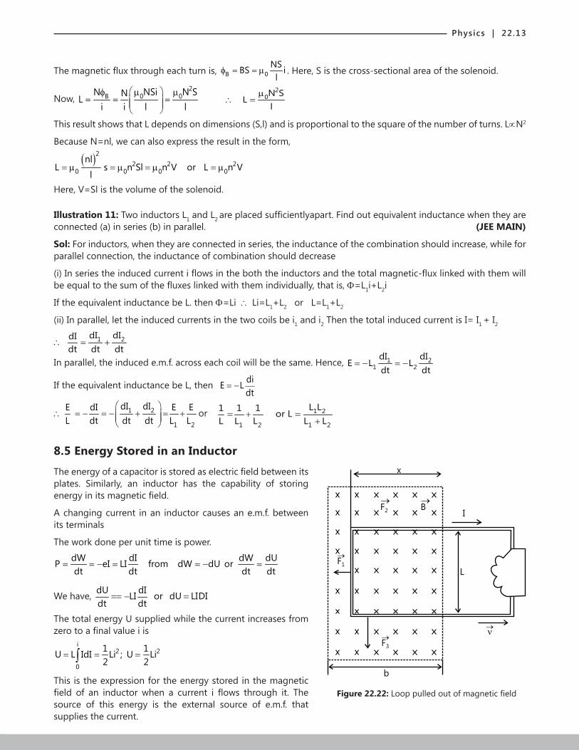
8.5 Energy Stored in an Inductor
The energy of a capacitor is stored as electric field between its
F2
B
F1
I
L
F3
x
b
Figure 22.22: Loop pulled out of magnetic field
plates. Similarly, an inductor has the capability of storing energy in its magnetic field.
A changing current in an inductor causes an e.m.f. between its terminals
The work done per unit time is power.
dW dI dW dUP eI LI from dW dU ordt dt dt dt
= = − = = − =
We have, dU dILI or dU LIDIdt dt
== − =
The total energy U supplied while the current increases from zero to a final value i is
i2 2
0
1 1U L IdI Li ; U Li2 2
= = =∫
This is the expression for the energy stored in the magnetic field of an inductor when a current i flows through it. The source of this energy is the external source of e.m.f. that supplies the current.
22.14 | Electromagnetic Induction and Electromagnetic Waves
Energy transfer
The rate at which you do work on the loop as you pull it from the magnetic field:2 2 2B LP FR
ν= ν = (rate of doing work).
The rate at which thermal energy appears in the loop as you pull it along at constant speed. 2P i R.=
Or, 2 2 2 2BL B LP R
R R ν ν
= =
(thermal energy rate), which is exactly equal to the rate at which you are doing work on
the loop.
Thus, the work that you do in pulling the loop through the magnetic field appears as thermal energy in the loop.
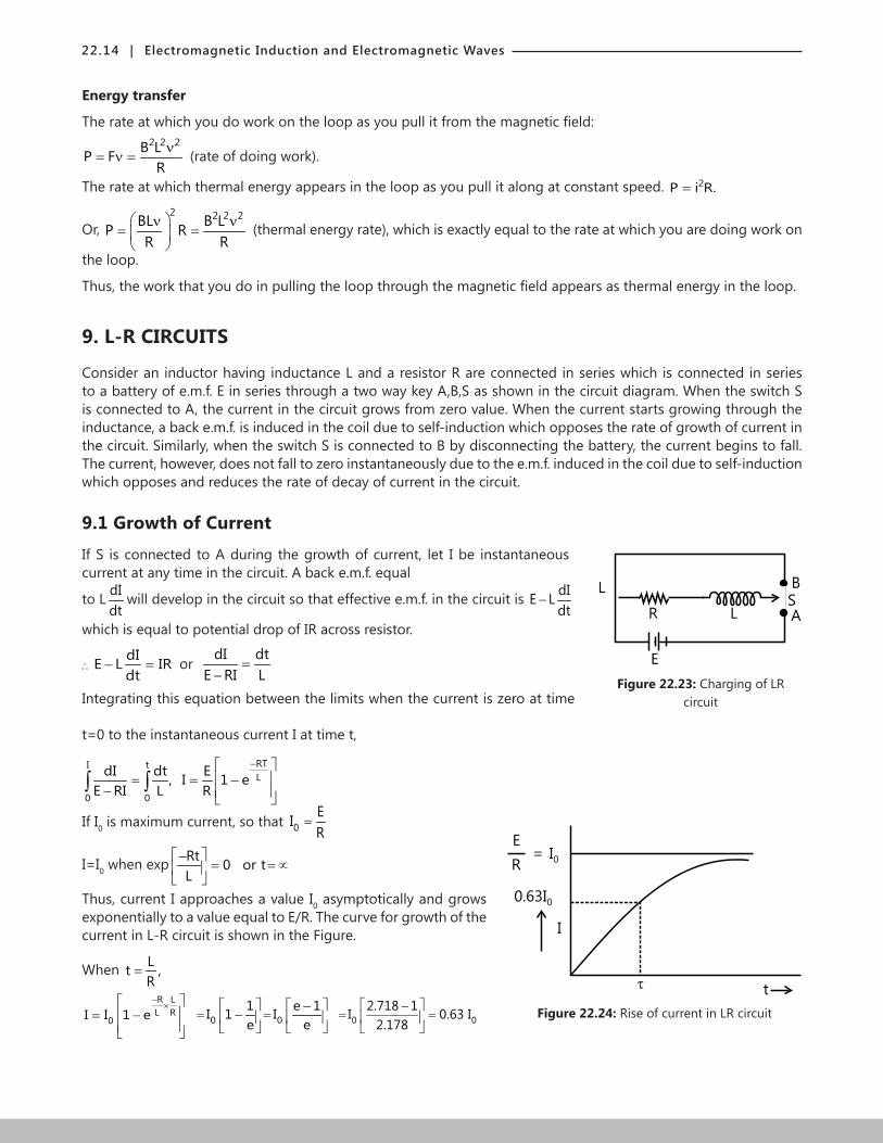
9. L-R CIRCUITS
Consider an inductor having inductance L and a resistor R are connected in series which is connected in series to a battery of e.m.f. E in series through a two way key A,B,S as shown in the circuit diagram. When the switch S is connected to A, the current in the circuit grows from zero value. When the current starts growing through the inductance, a back e.m.f. is induced in the coil due to self-induction which opposes the rate of growth of current in the circuit. Similarly, when the switch S is connected to B by disconnecting the battery, the current begins to fall. The current, however, does not fall to zero instantaneously due to the e.m.f. induced in the coil due to self-induction which opposes and reduces the rate of decay of current in the circuit.
9.1 Growth of Current
If S is connected to A during the growth of current, let I be instantaneous
L
R L
B
S
A
E
Figure 22.23: Charging of LR circuit
current at any time in the circuit. A back e.m.f. equal
to L dIdt
will develop in the circuit so that effective e.m.f. in the circuit is dIE Ldt
−
which is equal to potential drop of IR across resistor.
∴dIE L IRdt
− = or
dI dtE RI L
=−
Integrating this equation between the limits when the current is zero at time
t=0 to the instantaneous current I at time t,
RTI tL
0 0
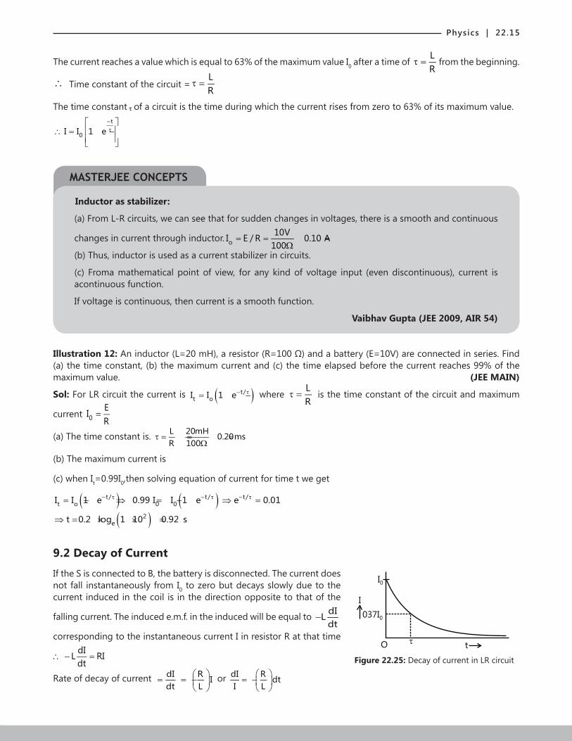
dI dt E, I 1 eE RI L R
− = = −
− ∫ ∫
If I0 is maximum current, so that 0EIR
=
Figure 22.24: Rise of current in LR circuit
E
R= I0
0.63I0
I
t
I=I0 when exp Rt 0 or tL
−= =
∝
Thus, current I approaches a value I0 asymptotically and grows exponentially to a value equal to E/R. The curve for growth of the current in L-R circuit is shown in the Figure.
When Lt ,R
=
R LL R
0I I 1 e−
× = −
0 01 e 1I 1 Ie e
−= − =
0 0
2.718 1I 0.63 I2.178
−= =
Physics | 22.15
The current reaches a value which is equal to 63% of the maximum value I0 after a time of LR
τ = from the beginning.
∴ Time constant of the circuit =LR
τ =
The time constant τ of a circuit is the time during which the current rises from zero to 63% of its maximum value. t
0I I 1 e−τ
∴ = −
Inductor as stabilizer:
(a) From L-R circuits, we can see that for sudden changes in voltages, there is a smooth and continuous
changes in current through inductor. oI E10010V/ R 0.10 A=
Ω= =
(b) Thus, inductor is used as a current stabilizer in circuits.
(c) Froma mathematical point of view, for any kind of voltage input (even discontinuous), current is acontinuous function.
If voltage is continuous, then current is a smooth function.
Vaibhav Gupta (JEE 2009, AIR 54)
Illustration 12: An inductor (L=20 mH), a resistor (R=100 Ω) and a battery (E=10V) are connected in series. Find
(a) the time constant, (b) the maximum current and (c) the time elapsed before the current reaches 99% of the maximum value. (JEE MAIN)
Sol: For LR circuit the current is ( )t/t oI I 1 e− τ= − where
LR
τ = is the time constant of the circuit and maximum
current 0EIR
=
(a) The time constant is. L 20mH 0.20msR 100
τ = = =Ω
(b) The maximum current is
(c) when It=0.99I0,then solving equation of current for time t we get
( ) ( )( )
t/ t/t o 0
t
2e
0/ e 0.01
t 0.2 log 1 10
I I 1 e 0
0.9
.99 I e
2
I 1
s
−− τ − τ τ= − ⇒ = − ⇒ =
⇒ = × × =
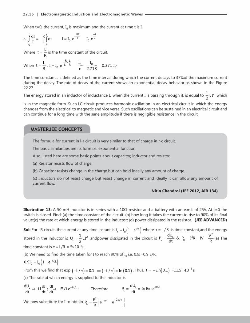
9.2 Decay of Current
If the S is connected to B, the battery is disconnected. The current does
Figure 22.25: Decay of current in LR circuit
I0
I
037I0
O t
not fall instantaneously from I0 to zero but decays slowly due to the current induced in the coil is in the direction opposite to that of the
falling current. The induced e.m.f. in the induced will be equal to dILdt
−
corresponding to the instantaneous current I in resistor R at that time dIL RIdt
∴ − =
Rate of decay of current dI R Idt L
= = −
or dI R dt
I L
= −
MASTERJEE CONCEPTS
22.16 | Electromagnetic Induction and Electromagnetic Waves
When t=0, the current, I0 is maximum and the current at time t is I.
I tt
I 00
RTL
0 0d I I e II R dt eI L
−−
τ∴ = == − ∴∫ ∫
Where LR
τ = is the time constant of the circuit.
When LtR
= ,R L
0 0L R0 0
I II I e 0.371 I
e 2.718
−×
= = = =
The time constant τ is defined as the time interval during which the current decays to 37%of the maximum current during the decay. The rate of decay of the current shows an exponential decay behavior as shown in the Figure 22.27.
The energy stored in an inductor of inductance L, when the current I is passing through it, is equal to 21 L I2
which
is in the magnetic form. Such LC circuit produces harmonic oscillation in an electrical circuit in which the energy changes from the electrical to magnetic and vice versa. Such oscillations can be sustained in an electrical circuit and can continue for a long time with the sane amplitude if there is negligible resistance in the circuit.
The formula for current in l-r circuit is very similar to that of charge in r-c circuit.
The basic similarities are its form i.e. exponential function.
Also, listed here are some basic points about capacitor, inductor and resistor.
(a) Resistor resists flow of charge.
(b) Capacitor resists change in the charge but can hold ideally any amount of charge.
(c) Inductors do not resist charge but resist change in current and ideally it can allow any amount of current flow.
Nitin Chandrol (JEE 2012, AIR 134)
Illustration 13: A 50 mH inductor is in series with a 10Ω resistor and a battery with an e.m.f. of 25V. At t=0 the switch is closed. Find: (a) the time constant of the circuit. (b) how long it takes the current to rise to 90% of its final value;(c) the rate at which energy is stored in the inductor; (d) power dissipated in the resistor. (JEE ADVANCED)
Sol: For LR circuit, the current at any time instant is ( )t/t oI I 1 e τ= − where L / Rτ = is time constant,and the energy
stored in the inductor is 2L
1U L I2
= andpower dissipated in the circuit is 2
2LL R
dU VP & P I R IVdt R
= = = = (a) The
time constant is τ = L/R = 5×10⁻³s.
(b) We need to find the time taken for I to reach 90% of I0 i.e. 0.9I=0.9 E/R.
( )t/0 00.9I I 1 e− τ= −
From this we find that exp ( )t / 0.1− τ = ( ) ( )t / In 0.1⇒ − τ = . Thus, ( ) 3t In 0.1 11.5 10 s−= −τ = ×
(c) The rate at which energy is supplied to the inductor is
Rt/L t/L LL
dU dUdI dILI ; / Le ; Therefore P I E edt dt dt dt
− − τ= + = + = = × ×E e
Rt/LLL
dUP I E e
dt−= = × ×
We now substitute for I to obtain 2 2t/t/
LEP e eR
− τ− τ = −
MASTERJEE CONCEPTS
Physics | 22.17
(d) The power dissipated in the resistor is 2t/2 2 t/
R 0P I R I R 1 2e e− τ− τ = = − +
From equation (iii), s Ps s P P
P s
E IE I E I or
E I= = . In general, E∝
1I
Illustration 14: (i) Calculate the inductance of an air core solenoid containing 300 turns if the length of the solenoid is 25.0 cm and its cross-sectional area is 4.00 cm2.
(ii) Calculate the self-induced e.m.f. in the solenoid if the current through it is decreasing at the rate of 50.0 A/s. (JEE MAIN)
Sol: For air core solenoid, inductance is calculated as 2
0N SL
lµ
= and the e.m.f. induced in solenoid is dIE Ldt
= −
(i) from the formula of inductance, 2
0N SL
lµ
= we ..have,
( )( ) ( )( )
27 44
2
4 10 300 4.00 10L H 1.81 10 H
25.0 10
− −−
−
π × ×= = ×
×
(ii) dIHere , 50.0 A / sdt
= − using formula of e.m.f. we get, ( )( )4 3E 1.81 10 50.0 9.05 10 V 9.05 mV− −= − × − = × =
10. ENERGY STORED IN A MAGNETIC FIELD
To derive a quantitative expression for that stored energy, consider a source of e.m.f. connected to a resistor R and an inductor L
If each side is multiplied by i, we obtain diL iR,dt
ξ = +
Which has the following physical interpretation in terms of work and energy: 2dii Li i R,dt
ξ = +
(a) If a differential amount of charge, dq passes through the battery of e.m.f. in time dt. The battery works on it in the amount dq. The rate at which the battery does work is (dq)/dt, or i. Thus, the left side of equation represents the rate at which the e.m.f. device delivers energy to the rest of the circuit.
(b) The term on the extreme right in the equation represents the rate at which energy appears as thermal energy in the resistor.
(c) Energy that is delivered to the circuit does not appear as thermal energy,but by the conservation-of-energy hypothesis, isstored in the magnetic field of the inductor. Because the equation represents the principle of conservation of energy for RL circuits, the middle term must represent the rate (dUB/dt) at which magnetic potential energy UB is stored in the magnetic field.
Thus BdU diLi .dt dt
= We can write this as BdU Li di.=
Integrating yieldsU iB
B0 0
dU Li di=∫ ∫ or 2B
1U Li2
= (magnetic energy), which represents the total energy stored by
inductor L carrying a current i.
Illustration 15: Calculate the energy stored in an inductor of inductance 50 mH when a current of 2.0 A is passed through it. (JEE MAIN)
Sol: In LR circuit, magnetic energy is stored in inductor is 2L
1U L I2
= ×
The energy stored is ( )( )22 31 1U Li 50 10 H 2.0A 0.10 J.2 2
−= = × =
22.18 | Electromagnetic Induction and Electromagnetic Waves
Illustration 16: What inductance would be needed to store 1.0 kWh of energy in a coil carrying a 200 A current? (1kWh=3.6×10⁻⁶J) (JEE MAIN)
Sol: In LR circuit, magnetic energy stored in inductor is 2L
1U L I2
= ×
We have, i=200 A and U=1kWh= 63.6 10 J−×
2
2UUsing formula of energy we get Li
∴ =( )( )
6
2
2 3.6 10180 H
200
×= =
11. ENERGY DENSITY OF A MAGNETIC FIELD
Consider a length l near the middle of a long solenoid of cross-sectional area A carrying current i; the volume associated with this length is Al. The energy UB stored by the length l of the solenoid must lie entirely within this volume because the magnetic field outside such a solenoid is approximately zero. Moreover, the stored energy must be uniformly distributed within the solenoid because magnetic field is (approximately) uniform everywhere inside.
Thus, the energy stored per unit volume of the field is BB
Uu
Al=
Or, since 2B
1U LI2
= , we have 2 2
BLI L IU2Al I 2A
= = .
Here L is the inductance of length l of the solenoid.
Substituting for 20
L n Al
= µ , we get 2 2B 0
1u n i2
= µ where n is the number of turns per unit length. We know that
0B in= µ , we can write this energy density as 2
B0
Bu2
=µ
(magnetic energy density).
This equation gives the density of stored energy at any point where the magnitude of the magnetic field is B. Even though we derived it by considering the special case of a solenoid, this equation holds for all magnetic fields, no
matter how they are generated. This equation is comparable to 2E 0
1u E2
= ε
Which gives the energy density (in a vacuum) at any point in an electric field. Note that both uB and uE are proportional to the square of the appropriate field magnitude, B or E.
Problem solving tactic
To solve the problems, one would need to learn many of the above formulae. For this, l simply advise that one should make analogy with electric field, capacitors, etc.
2B
1U LI2
= looks similar to 21 CV2
. A similar one for energy density formula is also available, where the electric field can
be replaced with magnetic field, and absolute permittivity with absolute permeability’s inverse.
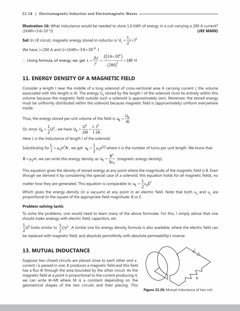
13. MUTUAL INDUCTANCE
Suppose two closed circuits are placed close to each other and a
i
R
Figure 22.26: Mutual inductance of two coil
current i is passed in one. It produces a magnetic field and this field has a flux Φ through the area bounded by the other circuit. As the magnetic field at a point is proportional to the current producing it, we can write Φ=MI where M is a constant depending on the geometrical shapes of the two circuits and their placing. This
Physics | 22.19
constant is called mutual inductance of the given pair of circuits. If the same current i is passed in the second circuit and the flux is calculated through the area bounded by the circuit, the same proportionality constant M appears. If there ismore than one turn in a circuit, one has to add the flux through each turn before applying the above equation.
If the current i in one circuit changes with time, the flux through the area bounded by the second circuit also changes. Thus, an e.m.f. is induced in the second circuit. This phenomenon is called mutual induction. From
theabove equation, the induced e.m.f. is d diE Mdt dtΦ
= − = − dIdt
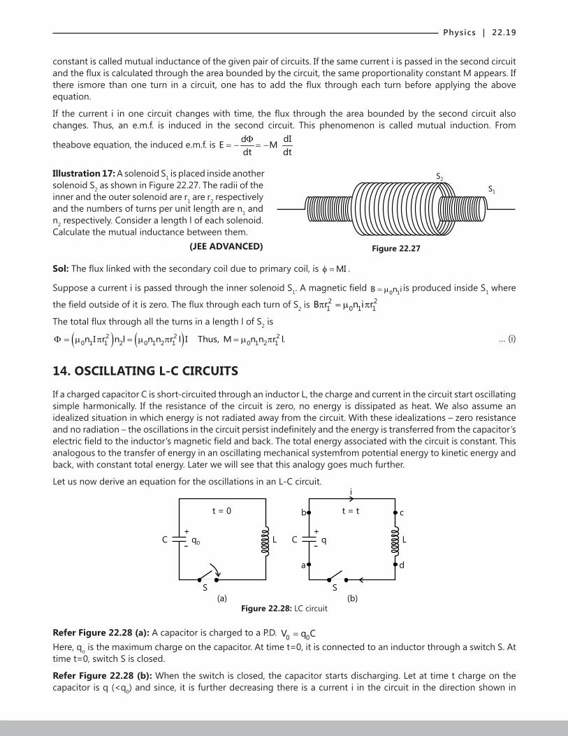
Illustration 17: A solenoid S1 is placed inside another
Figure 22.27
S2
S1
solenoid S2 as shown in Figure 22.27. The radii of the inner and the outer solenoid are r1 are r2 respectively and the numbers of turns per unit length are n1 and n2 respectively. Consider a length l of each solenoid. Calculate the mutual inductance between them. (JEE ADVANCED)
Sol: The flux linked with the secondary coil due to primary coil, is MIφ = .
Suppose a current i is passed through the inner solenoid S1. A magnetic field 0 1B n i= µ is produced inside S1 where
the field outside of it is zero. The flux through each turn of S2 is 2 21 0 1 1B r n i rπ = µ π
The total flux through all the turns in a length l of S2 is
( ) ( )2 2 20 1 1 2 0 1 2 1 0 1 2 1n I r n l n n r l I Thus, M n n r l.Φ = µ π = µ π = µ π
… (i)
14. OSCILLATING L-C CIRCUITS
If a charged capacitor C is short-circuited through an inductor L, the charge and current in the circuit start oscillating simple harmonically. If the resistance of the circuit is zero, no energy is dissipated as heat. We also assume an idealized situation in which energy is not radiated away from the circuit. With these idealizations – zero resistance and no radiation – the oscillations in the circuit persist indefinitely and the energy is transferred from the capacitor’s electric field to the inductor’s magnetic field and back. The total energy associated with the circuit is constant. This analogous to the transfer of energy in an oscillating mechanical systemfrom potential energy to kinetic energy and back, with constant total energy. Later we will see that this analogy goes much further.
Let us now derive an equation for the oscillations in an L-C circuit.
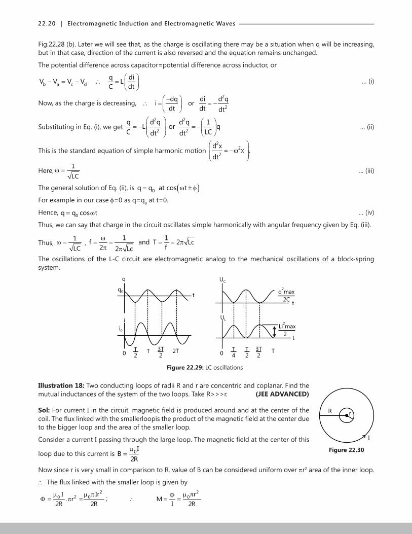
Figure 22.28: LC circuit
t = 0
LC q0
+
-
S
(a) (b)
t = t
LC q+
-
S
i
b
a d
c
Refer Figure 22.28 (a): A capacitor is charged to a P.D. 0 0V q C=Here, qo is the maximum charge on the capacitor. At time t=0, it is connected to an inductor through a switch S. At time t=0, switch S is closed.
Refer Figure 22.28 (b): When the switch is closed, the capacitor starts discharging. Let at time t charge on the capacitor is q (<q0) and since, it is further decreasing there is a current i in the circuit in the direction shown in
22.20 | Electromagnetic Induction and Electromagnetic Waves
Fig.22.28 (b). Later we will see that, as the charge is oscillating there may be a situation when q will be increasing, but in that case, direction of the current is also reversed and the equation remains unchanged.
The potential difference across capacitor=potential difference across inductor, or
b a c dq diV V V V LC dt
− = − ∴ =
… (i)
Now, as the charge is decreasing, 2
2
dq di d qi ordt dt dt
−∴ = = −
Substituting in Eq. (i), we get 2 2
2 2
q d q d q 1L or qC LCdt dt
= − = −
… (ii)
This is the standard equation of simple harmonic motion 2
22
d x x .dt
= −ω
Here,1
LCω = ... (iii)
The general solution of Eq. (ii), is ( )0q q at cos t= ω ± φ
For example in our case f=0 as q=q0 at t=0.
Hence, 0q q cos t= ω … (iv)
Thus, we can say that charge in the circuit oscillates simple harmonically with angular frequency given by Eq. (iii).
Thus, 1
LCω = ,
1 1f and T 2 Lc2 f2 Lc
ω= = = = π
π πThe oscillations of the L-C circuit are electromagnetic analog to the mechanical oscillations of a block-spring system.
q
q0
i0
T
2T 3T
22T
t
UC
UL
q max2
2Ct
Li max2
2t
T
2
T
4
3T
2T
0 0
i
Figure 22.29: LC oscillations
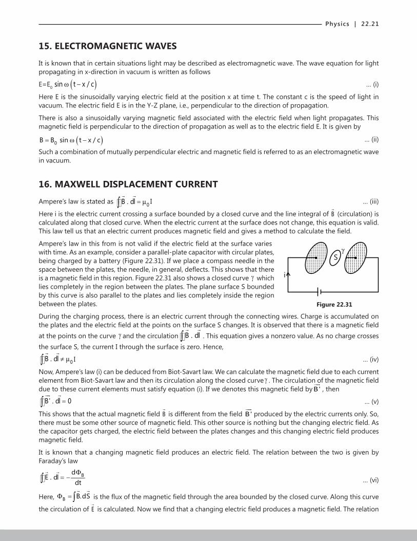
Illustration 18: Two conducting loops of radii R and r are concentric and coplanar. Find the
R r
I
Figure 22.30
mutual inductances of the system of the two loops. Take R>>>r. (JEE ADVANCED)
Sol: For current I in the circuit, magnetic field is produced around and at the center of the coil. The flux linked with the smallerloopis the product of the magnetic field at the center due to the bigger loop and the area of the smaller loop.
Consider a current I passing through the large loop. The magnetic field at the center of this
loop due to this current is 0IB
2Rµ
=
Now since r is very small in comparison to R, value of B can be considered uniform over πr2 area of the inner loop.
∴ The flux linked with the smaller loop is given by 2
20 0I Ir. r
2R 2Rµ µ π
Φ = π = ; 2
0 rM
I 2Rµ πΦ
∴ = =
Physics | 22.21
15. ELECTROMAGNETIC WAVES
It is known that in certain situations light may be described as electromagnetic wave. The wave equation for light propagating in x-direction in vacuum is written as follows
E=E0 ( )0B B sin t x / c= ω − … (i)
Here E is the sinusoidally varying electric field at the position x at time t. The constant c is the speed of light in vacuum. The electric field E is in the Y-Z plane, i.e., perpendicular to the direction of propagation.
There is also a sinusoidally varying magnetic field associated with the electric field when light propagates. This magnetic field is perpendicular to the direction of propagation as well as to the electric field E. It is given by
( )0B B sin t x / c= ω − … (ii)
Such a combination of mutually perpendicular electric and magnetic field is referred to as an electromagnetic wave in vacuum.
16. MAXWELL DISPLACEMENT CURRENT
Ampere’s law is stated as 0B . dl i= µ∫
I … (iii)
Here i is the electric current crossing a surface bounded by a closed curve and the line integral of B (circulation) is
calculated along that closed curve. When the electric current at the surface does not change, this equation is valid. This law tell us that an electric current produces magnetic field and gives a method to calculate the field.
Ampere’s law in this from is not valid if the electric field at the surface varies
S
i
Figure 22.31
with time. As an example, consider a parallel-plate capacitor with circular plates, being charged by a battery (Figure 22.31). If we place a compass needle in the space between the plates, the needle, in general, deflects. This shows that there is a magnetic field in this region. Figure 22.31 also shows a closed curve γ which lies completely in the region between the plates. The plane surface S bounded by this curve is also parallel to the plates and lies completely inside the region between the plates.
During the charging process, there is an electric current through the connecting wires. Charge is accumulated on the plates and the electric field at the points on the surface S changes. It is observed that there is a magnetic field at the points on the curve γ and the circulation B . dl∫
. This equation gives a nonzero value. As no charge crosses the surface S, the current I through the surface is zero. Hence,
0B . dl i≠ µ∫
I … (iv)
Now, Ampere’s law (i) can be deduced from Biot-Savart law. We can calculate the magnetic field due to each current element from Biot-Savart law and then its circulation along the closed curve γ . The circulation of the magnetic field due to these current elements must satisfy equation (i). If we denotes this magnetic field byB'
, then
B' . dl 0=∫
… (v)
This shows that the actual magnetic field B is different from the field B'
produced by the electric currents only. So,
there must be some other source of magnetic field. This other source is nothing but the changing electric field. As the capacitor gets charged, the electric field between the plates changes and this changing electric field produces magnetic field.
It is known that a changing magnetic field produces an electric field. The relation between the two is given by Faraday’s law
BdE . dl
dtΦ
= −∫
… (vi)
Here, B B.dSΦ =∫
is the flux of the magnetic field through the area bounded by the closed curve. Along this curve
the circulation of E
is calculated. Now we find that a changing electric field produces a magnetic field. The relation
22.22 | Electromagnetic Induction and Electromagnetic Waves
between the changing electric field and the magnetic field resulting from it is given by
E0 0
dB . dl
dtΦ
= µ ε∫
… (vii)
Here, EΦ is the flux of the electric field through the area bounded by the closed curve along which the circulation of B
is calculated. Equation (iii) gives the magnetic field resulting from an electric current due to flow of charges.
Equation (vii) gives the magnetic field due to the changing electric field. If there exists an electric current as well as a changing electric field, the resultant magnetic field is given by
E0 0 0
dB.dl i
dt Φ
= µ +µ ε
∫
Or, ( )0 dB.dl i i= µ +∫
… (viii)
In the above equation Ed 0
di
dtΦ
= ε is the displacement current.
Illustration 19: For a charging parallel plate capacitor, prove that the displacement current across an area in the region between the plates and parallel to it is equal to the conduction current in the connecting wires.
Sol: For electric flux ΦE associated with the surface of one of the parallel plates, the displacement current in and
across the area of the parallel plate is Ed 0
di
dtΦ
=ε .
The electric field between the plates is0
QEA
=ε
Where Q is the charge accumulated at the positive plate. The flux of this field through the given area is
E0 0
Q QAA
Φ = × =ε ε
The displacement current is Ed 0 0
0
d d Q dQidt dt dt
Φ=ε =ε = ε
But dQdt
is the rate at which the charge is carried to the positive plate through the connecting wire. Thus, id=ic
17 MAXWELL’S EQUATIONS AND PLANE ELECTROMAGNETIC WAVES.
We can summarize the concepts of electricity and magnetism mathematically with the help of four fundamental equations:
Gauss’s law for electricity 0
qE dS⋅ =ε∫
… (ix)
Gauss’s law for magnetism B dS 0⋅ =∫
… (x)
Faraday’s law BdE dl
dtΦ
⋅ = −∫
… (xi)
Ampere’s law E0 0 0
dB dl i
dtΦ
⋅ = µ + ε µ∫
… (xii)
These equations are collectively known as Maxwell’s equations.
In vacuum, there are no charges and hence no conduction currents. Faraday’s law and Ampere’s law take the form
Bd
E dldtΦ
⋅ = −∫
... (xiii)
Physics | 22.23
and E0 0
dB dl
dtΦ
⋅ = µ ε −∫
… (xiv)
Respectively.
Let us check if these equations are satisfied by a plane electromagnetic wave given by
y 0
z 0
E E E .sin (t x/ c)
B B B sin (t x/ c)and
= = ω −
= = ω − … (xv)
The wave described above propagates along the positive x-direction, the electric field remains along the y-direction and the magnetic field along the z-direction. The magnitudes of the fields oscillate between 0 0E and B± ± respectively. It is a linearly polarized light, polarized along the y-axis.
From the theory of the waves, we can prove the relations between electric and magnetic field represented in equation (xv) as
0 0E c B .= … (xvi)
0 0 0 0 0 0 2
1B c Ec
= µ ε ⇒ µ ε = … (xvii)
Or, 0 0
1c =µ ε
… (xviii)
The wave number 2k π
=λ
and speed of light in vacuum is o
o o o
E 1c fk Bω
= = λ = =ε µ
In general the speed of electromagnetic waves in the medium of electric permittivity ε and magnetic permeability
µ is 1v =µ ε
Illustration 20: The maximum electric field in a plane electromagnetic wave is 900 N C-1. The wave is going in the x-direction and the electric field is in the y-direction. Find the maximum magnetic field in the wave and its direction.
Sol: The magnetic field is found using the relation 0 0E c B=
We have 1
600 8 1
E 900 NCB 3 10 T.
c 3 10 ms
−−
−= = = ×
×
As E,B
and the direction of propagation are mutually perpendicular, B
should be along the z-direction.
18 ENERGY DENSITY AND INTENSITY IN ELECTROMAGNETIC WAVE
The electric and magnetic field in a plane electromagnetic wave are given by
0E E sin (t x/ c)= ω − and 0B B sin (t x/ c).= ω −
In any small volume dV, the energy of the electric field is 2E 0
1U E dV2
= ε … (xix)
And the energy of the magnetic field is 2B
0
1U B dV2
=µ
… (xx)
Thus, the total energy is 2 20
0
1 1U E dV B dV2 2
= ε +µ
… (xxi)
The energy density is 2 20
0
1 1u E B2 2
= ε +µ
2 2 2 20 0 0
0
1 1E sin (t x/ c) B sin (t x/ c)2 2
= ε ω − + ω −µ
… (xxii)
If we take the average over a long time, the sin2 terms have an average value of ½ Thus,
22.24 | Electromagnetic Induction and Electromagnetic Waves
2 2au 0 0 0
0
1 1u E B4 4
= ε +µ
… (xxiii)
From equations (xvi) and (xx)
0 0 0 0 2
1E cB andc
= µ ε = so that, 22
2 20 00 0 0
0
c E1 1B E4 4 c 4
ε= = ε µ
Thus, the electric energy density is equal to the magnetic energy density in average.
Or, 2 2 2av 0 0 0 0 0 0
1 1 1u E E E4 4 2
= ε + ε = ε ... (xxiv)
Also, 2 2 2av 0 0 0
0 0 0
1 1 1u B B B .4 4 2
= + =µ µ µ
... (xxv)
Illustration 21: The electric field in an electromagnetic wave is given by 1E (50 NC )sin (t x/ c)−= ω − . Find the energy contained in a cylinder of cross-section 10 cm2 and length 50 cm along the x-axis.
Sol: The energy of electric field is given by 2E 0
1U V E2
= ε where V is the volume of the cylinder
The energy density is 2 12 2 1 2 1 2av 0 0
1 1u E (8.55 10 C N m ) (50 NC )2 2
− − − −= ε = × × × 8 31 1 10 Jm− −= ⋅ ×
The volume of the cylinder is V=10 cm2 x 50 cm=5 x 10⁻⁴ m3.
The energy contained in this volume is 8 3 4 3U (1 1 10 Jm ) (5 10 m )− − −= ⋅ × × × 125 5 10 J−= ⋅ ×
Intensity
The energy crossing per unit area per unit time perpendicular to direction of propagation is called the intensity of a wave.
c t
A x
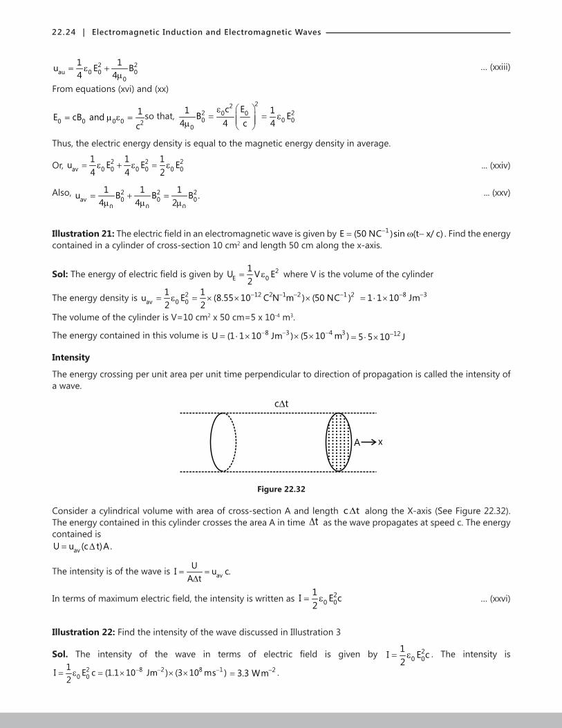
Figure 22.32
Consider a cylindrical volume with area of cross-section A and length c t∆ along the X-axis (See Figure 22.32). The energy contained in this cylinder crosses the area A in time t∆ as the wave propagates at speed c. The energy contained is
avU u (c t)A.= ∆
The intensity is of the wave is avUI u c.
A t= =
∆
In terms of maximum electric field, the intensity is written as 20 0
1I E c2
= ε … (xxvi)
Illustration 22: Find the intensity of the wave discussed in Illustration 3
Sol. The intensity of the wave in terms of electric field is given by 20 0
1I E c2
= ε . The intensity is 2 8 2 8 1
0 01I E c (1.1 10 Jm ) (3 10 ms )2
− − −= ε = × × × 23.3 Wm−= .
Physics | 22.25
19. MOMENTUM
The propagating electromagnetic wave also carries linear momentum with it. The linear momentum carried by the
portion of wave having energy U is given by Upc
= … (xxvii)
Thus, if the wave incident on a material surface is completely absorbed, it delivers energy U and momentum p=U/c to the surface. If the wave is totally reflected, the momentum delivered to the surface of the material is 2U/c because the momentum of the wave changes from p to –p. It follows that electromagnetic waves incident on a surface exert a force on the surface.
20. ELECTROMAGNETIC SPECRUM AND RADIATION IN ATMOSPHERE
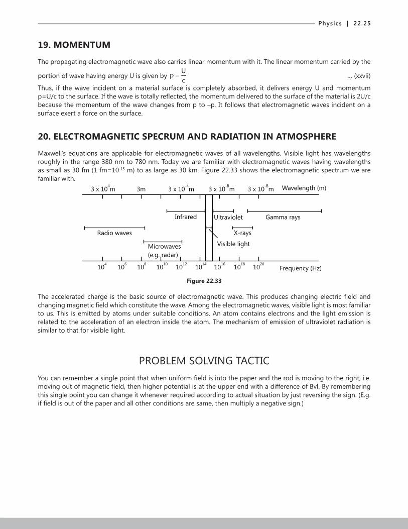
Maxwell’s equations are applicable for electromagnetic waves of all wavelengths. Visible light has wavelengths roughly in the range 380 nm to 780 nm. Today we are familiar with electromagnetic waves having wavelengths as small as 30 fm (1 fm=10-15 m) to as large as 30 km. Figure 22.33 shows the electromagnetic spectrum we are familiar with.
3 x 10 m4
3m 3 x 10 m-4
3 x 10 m-B
3 x 10 m-B
Wavelength (m)
Radio waves
Infrared Ultraviolet Gamma rays
X-rays
Visible lightMicrowaves
(e.g. radar)
104
106
108
1010
1012
1014
1016
1018
1020
Frequency (Hz)
Figure 22.33
The accelerated charge is the basic source of electromagnetic wave. This produces changing electric field and changing magnetic field which constitute the wave. Among the electromagnetic waves, visible light is most familiar to us. This is emitted by atoms under suitable conditions. An atom contains electrons and the light emission is related to the acceleration of an electron inside the atom. The mechanism of emission of ultraviolet radiation is similar to that for visible light.
PROBLEM SOLVING TACTICYou can remember a single point that when uniform field is into the paper and the rod is moving to the right, i.e. moving out of magnetic field, then higher potential is at the upper end with a difference of Bvl. By remembering this single point you can change it whenever required according to actual situation by just reversing the sign. (E.g. if field is out of the paper and all other conditions are same, then multiply a negative sign.)
22.26 | Electromagnetic Induction and Electromagnetic Waves
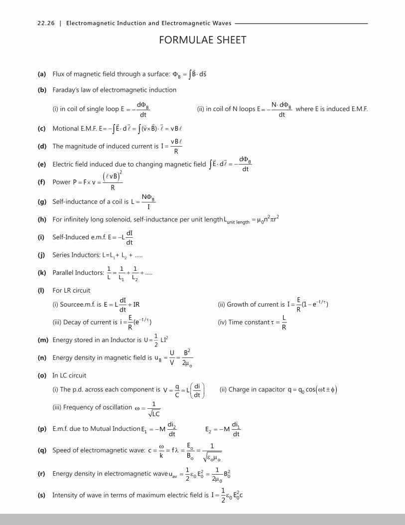
FORMULAE SHEET
(a) Flux of magnetic field through a surface: B B dsΦ = ⋅∫
(b) Faraday’s law of electromagnetic induction
(i) in coil of single loop E BddtΦ
ξ = − (ii) in coil of N loops E BN ddt
⋅ Φξ = − where E is induced E.M.F.
(c) Motional E.M.F. E E d (v B) vBξ = − ⋅ = × ⋅ =∫ ∫
(d) The magnitude of induced current is vB
IR
=
(e) Electric field induced due to changing magnetic field BdE d
dtΦ
⋅ = −∫
(f) Power ( )2
vBP F v
R= × =
(g) Self-inductance of a coil is BNL
IΦ
=
(h) For infinitely long solenoid, self-inductance per unit length 2 2unit length 0L n r= µ π
(i) Self-Induced e.m.f. E dILdt
ξ = −
( j) Series Inductors: L=L1+ L2 + …..
(k) Parallel Inductors: 1 2
1 1 1 .....L L L
= + +
(l) For LR circuit
(i) Sourcee.m.f. is dIE L IRdt
= + (ii) Growth of current is t /EI (1 e )R
− τ= −
(iii) Decay of current is t /Ei (e )R
− τ= (iv) Time constantLR
τ =
(m) Energy stored in an Inductor is 21U L I2
=
(n) Energy density in magnetic field is 2
Bo
U BuV 2
= =µ
(o) In LC circuit
(i) The p.d. across each component is q diV LC dt
= =
(ii) Charge in capacitor ( )0q q cos t= ω ± φ
(iii) Frequency of oscillation 1
LCω =
(p) E.m.f. due to Mutual Induction 21
diE M
dt= − 1
2di
E Mdt
= −
(q) Speed of electromagnetic wave: o
o o o
E 1c fk Bω
= = λ = =ε µ
(r) Energy density in electromagnetic wave 2 2av 0 0 0
0
1 1u E B2 2
= ε =µ
(s) Intensity of wave in terms of maximum electric field is 20 0
1I E c2
= ε