222 product guide - bigge crane and rigging · upperworks engine 222: cummins 6 cta 8.3c diesel, 6...
TRANSCRIPT

da
tamodel 222
productguide
features• 91 mton (100 ton) capacity
• 307 mton-m (2,224 ft-kips)Maximum Load Moment
• 61,0 m (200') Heavy-Lift Boom
• 76,2 m (250') Fixed Jibon Heavy-Lift Boom
• 80,8 m (265') Luffing Jibon Heavy-Lift Boom
• 96,0 m (315') Fixed Jib on Luffing Jibon Heavy-Lift Boom
• 172 kW (230 HP) engine standard
• 261 kW (350 HP) engine EX & HD
• EPIC4 controls
• 174 m/min (570 fpm) line speed
• 89 kN (20,000 lb) line pull standard
• 178 kN (40,000 lb) line pull EX & HD
• 8 000 kg (17,600 lb) Clamshell capacity
• 13 600 kg (30,000 lb) Clamshell capacity HD
• 8 160 kg (18,000 lb) Dragline capacity
• Fast, efficient self-assembly
• Complete crane, maximum boom, fixed jiband counterweight ships on only 3 trucks
• Manitowoc CraneCARESM
contents
Specifications 2Outline Dimensions 6Transport Data 12Crane Assembly 13Performance Data 14
Boom Combinations 18Heavy-Lift Boom Range Diagram 20Heavy-Lift BoomLoad Charts 21Heavy-Duty Boom (HD) Range Diagram 22Heavy-Duty Boom (HD)Load Charts 23Fixed JibRange Diagram 24Fixed JibLoad Charts 25Luffing JibRange Diagram 29Luffing JibLoad Charts 30Fixed Jib on Luffing JibRange Diagram 32Fixed Jib on Luffing JibLoad Charts 33CraneCARESM 34

Upperworks
Engine
222: Cummins 6 CTA 8.3C diesel, 6 cylinder, 172 kW(230 BHP) @ 2200 governed RPM.
One 12 volt maintenance-free, Group 8D battery, 1400CCA at -18°C (0° F), 12 volt starting and 80 ampalternator.
222EX & 222HD: Cummins M11 diesel, 6 cylinder,261 kW (350 BHP) @ 2100 governed RPM.
Two 12 volt maintenance-free, Group 8D batteries, 1400CCA at -18°C (0° F), 12 volt starting and 100 ampalternator.
Optional additional pad for mounting of accessoryhydraulic pumps on Cummins M11 only.
Manually operated disconnect clutch for cold weatherstarting. Multiple hydraulic pump drive transmissionprovides independent power for all machine functions.
Optional: consult factory for other available engines.
One 340 l (90 gal) capacity diesel fuel tank, mounted onrear of upperworks, with level indicator in operator’s cab.
Controls
Modulating electronic-over-hydraulic controls provideinfinite speed response directly proportional to controllever movement. Controls include Manitowoc's exclusiveEPIC® Electronic Processed Independent Controls systemproviding microprocessor driven control logic, pumpcontrol, on-board diagnostics, and service information.
Block-up limit control is standard for hoist and whiplines.
Integrated Load Moment Indicator system (LMI) isstandard for main boom, upper boom point, and fixed jib.“Function cut-out” or “warning only” operation isavailable via a keyed switch on the LMI console.
Optional travel and swing alarms are available.
Hydraulic System
Six high-pressure piston pumps are driven through amulti-hydraulic pump transmission. These six pumpsprovide independent "closed loop" hydraulic power forfront drum, rear drum, boom hoist system, swing system,and both left and right crawler operation.
System kg/cm2 (psi) lpm (gpm)Front Drum 422 (6,000) 284 (75)Rear Drum 422 (6,000) 284 (75)Boom Hoist 422 (6,000) 155 (41)Swing System 316 (4,500) 155 (41)Left Crawler 422 (6,000) 155 (41)Right Crawler 422 (6,000) 155 (41)
Hydraulic reservoir capacity is 568 l (150 gal) and isequipped with breather, dipstick, clean out access, andinternal diffuser.
Each function is equipped with relief valves to protect thehydraulic circuit from overload or shock.
Replaceable, spin on ten micron (absolute) full flow linefilter is furnished in the hydraulic circuit. All oil is filteredprior to return to the hydraulic reservoir.
Hydraulic system also includes pump transmissiondisconnect clutch & hydraulic oil cooler.
Optional 222EX & 222HD only: Open LoopHydraulic Power Package consists of: low profile 1 022liter (270 gal) hydraulic tank mounted along the top leftside of machinery enclosure. Additional hydraulic oilcooler and fan assembly. One main hydraulic pump upto 492 lpm (130 gpm). One pilot hydraulic pump. Tenmicron filtration system and machine plumbing.Hydraulic manifold with up to five quick-disconnectcouplings mounted on the front of the machine. Primarycontrols and valving.
Drums
Two equal width winches 543 mm (21-3/8") wide aredriven by independent variable displacement axial pistonhydraulic motors through planetary reduction mountedon separate front and rear shafts with anti-frictionbearings.
Front Hoist Diameter Max Line Pull222, 222EX 483 mm (19") 89 kn (20,000 lb)222HD 647 mm (25-1/2") 178 kn (40,000 lb)
Rear Hoist Diameter Max Line PullAll Models 483 mm (19") 89 kn (20,000 lb)
Optional 222HD only: 178 kn (40,000 lb) high pullrear hoist drum can be ordered in place of standard rear543 mm (21-3/8") wide 647 mm (25-1/2") diameterdrum.
Powered hoisting/lowering and free-fall operation isstandard with automatic (spring applied, hydraulicallyreleased) multi-disc brakes, clutches, and drum rotationindicators.
2
specificationsm
od
el
22
2

Free-fall operation for front and rear drums includesinternally expanding clutch assembly and externalcontracting band brake manually applied by foot pedalwith locking latch in operator’s cab. Operator may selectfree-fall or powered lowering mode using a selectorswitch.
Optional auxiliary (third) hydraulic powered drumrated at 66,7 kN (15,000 lb) line pull for third line overupper boom point, or luffing jib intermediate fall,mounted on front of rotating bed. Includes third sheavewith boom top wire rope guide and boom butt wire ropeguide and third drum control system.
Optional auxiliary drum rated at 66,7 kN (15,000 lb)line pull as described above, mounted in boom butt.
Optional 222EX & 222HD only: 111 kN (25,000lb) third hydraulic drum, for third line over boom pointor luffing jib intermediate fall, mounted on front ofrotating bed. Includes third sheave with boom top wirerope guide and boom butt wire rope guide and thirddrum control system.
Optional auxiliary drum preparation includes electricwiring and hydraulic plumbing.
Optional bolt-on liftcrane laggings.
Optional bolt-on clamshell laggings.
Optional wire rope for various applications(seepages14-15).
Boom Hoist
Independent two-drum boom hoist with grooved drumsincluding 131,1 m (430') of 15,88 mm (5/8") diameterwire rope reeved with 10 parts of line.
Drums are powered by a fixed displacement hydraulicmotor coupled to an internal brake and planetary gearboxequipped with ratcheting pawl.
Boom hoist speed: raise 61,0 m (200') full main boomfrom 0˚- 82˚ in 80 seconds.
Swing System
High strength fabricated steel alloy rotating bed ismounted on 1,64 m (64-3/4") diameter turntable bearing.
Reinforced rotating bed for duty cycle operation on the222EX & 222HD.
Independent swing powered by a fixed displacementhydraulic motor coupled to a planetary gearbox withinternal brake. 360˚ positive swing lock.
Swing system maximum speed: 3.6 rpm.
Counterweight
Total standard upper counterweight assembly is 24 177 kg(53,000 lb) consisting of one inner 12 927 kg (28,500 lb)counterweight and one outer 11 249 kg (24,800 lb)counterweight.
During self-assembly, the crane boom butt and hoist areused to lift the counterweights up onto lugs at the rear ofthe rotating bed upperworks via a tethered remotecontrol. The counterweights are then secured in place bytwo pins for fast, safe assembly.
Optional Series B counterweight system consisting ofone 4 536 kg (10,000 lb) middle counterweight box andfour crawler frame counterweights at 1 588 kg (3,500 lb)each. Includes connecting pins, brackets, and stops.
Operator’s Cab
Fully enclosed and insulated steel module mounted to theleft front corner of rotating bed. Module is equippedwith sliding door, large safety glass windows on all sidesand roof. Signal horn, cab space heater, front and roofwindshield wipers, dome light, sun visor and shade, fireextinguisher and air circulating fan are standardequipment.
Optional air conditioning for operator’s cab.
Optional nylon protective window covers foroperator’s cab.
Attachments
No. 222 Heavy-Lift Main Boom
The base 222 & 222EX liftcranes come standard with a12,2 m (40') No. 222 basic heavy-lift tubular chord boomconsisting of a 5,8 m (19') butt and 6,4 m (21') openthroat top with four 50,8 cm (20") diameter roller bearingsheaves on one shaft.
The basic heavy-lift boom also includes a boom angleindicator, pendant rigging, cushioned boom stops, andautomatic boom hoist stop.
Anti-two block limit controls for main and whip lines.
4,7 m (15' 6") gantry and telescopic backhitch with anti-friction bearings and nylon sheaves in gantryand equalizer system.
Optional No. 222 3,0 m (10'), 6,1 m (20'), and 12,2 m (40') main boom inserts with pendants.
3
specifications
mo
de
l2
22

Optional 222 & 222EX detachable upper boompoint with one 50.8 cm (20") roller bearing steel sheavegrooved for 22,23 mm (7/8") diameter rope with ropeguard for lift crane.
No. 222HD Heavy-Duty Main Boom
The base 222HD liftcrane comes standard with a 12,2 m(40') No. 222HD basic heavy-duty tubular chord boomconsisting of 5,8 m (19') butt and 6,4 m (21') openthroat top with two 86,3 cm (34") diameter taper rollerbearing sheaves on one shaft.
The basic heavy-duty boom also includes a boom angleindicator, pendant rigging, cushioned boom stops, andautomatic boom hoist stop.
Anti-two block limit controls for main and whip lines.
4,7 m (15' 6") gantry and telescopic backhitch with anti-friction bearings and nylon sheaves in gantryand equalizer system.
Optional No. 222HD 3,0 m (10') and 6,1 m (20')main boom inserts with pendants.
Note: 222HD utilizes No. 222 12,2 m (40') insert(s).
Optional 222HD heavy duty detachable upper boompoint with one 76,2 cm (30") roller bearing steel sheavegrooved for 31,75 mm (1-1/4") diameter rope with ropeguard for liftcrane.
No. 10 Fixed Jib
Optional No. 10 basic fixed jib 9,1 m (30') lengthconsisting of 4,6 m (15') jib butt and 4,6 m (15') jib topwith 3,7 m (12') jib strut, pendants and backstay.
Optional No. 10 fixed jib inserts 3,0 m (10’).
Utilize up to three fixed jib inserts in combination withthe No. 10 basic fixed jib for total lengths of 12,2 m(40'), 15,2 m (50'), and 18,3 m (60').
Optional jib point roller assembly for use on No. 10fixed jib extension on No. 222 luffing jib.
No. 260 Boom
for No. 222 Luffing Jib
Optional 16,8 m (55') basic No. 260 boom for No.222 luffing jib assembly consisting of: 8,8 m (29') No.260 transition insert with wire rope guide, 2,1 m (7')boom cap assembly, pendants for transition and cap, andpendant spreader.
Note: above utilizes existing 5,8 m (19') No. 222 boombutt from base crane.
Optional 3,0 m (10'), 6,1 m (20'), and 12,2 m (40')No. 260 boom inserts with pendants.
No. 222 Luffing Jib
requires No. 260 Main Boom
Optional 15,2 m (50') basic No. 222 luffing jibassembly consisting of: 5,8 m (19') No. 222 luffing jibbutt with one 48,9 cm (19-1/4") diameter roller bearingsheave (intermediate-fall), 4,8 m (16') fixed strutassembly, 4,8 m (16') jib strut assembly, jib stop assembly,backstay pendants, luffing jib point roller assembly, 51,9cm (20-7/16") grooved bolt-on lagging for luffing (reardrum), luffing jib hoist line, block up limit, LMI (loadmoment indicator) hardware for intermediate-fall, luffingjib, and fixed jib extension on luffing jib
Note: above utilizes existing 3,0 m (10') No. 222 boominsert and existing 6,4 m (21') No. 222 boom top frombase crane – use existing No. 222 inserts for longerlengths)
Lowerworks
Carbody
Steel fabricated carbody with wide flange wings formounting to crawler side frames.
Two variable displacement travel motors driven throughplanetary gearboxes provide narrow-profile mountingwithin the crawler modules.
Crawlers
Crawler assemblies are 6,83 m (22' 5") long with 91,4cm (36") wide cast steel crawler pads.
Crawlers have full counter-rotation capability.
Hydraulic extension/retraction of crawler assemblies withtethered remote control.
Maximum ground speed of 1,56 kph (0.97 mph).
Optional crawler handling package includes a highcapacity wire rope guide mounted on the boom butt,sheave frame that attaches to the boom butt, single sheave20 mton (22 ton) self assembly block for 22 mm (7/8")or 31 mm (1-1/4") wire rope, and four 1,8 m (6') nyloneye round slings.
4
specificationsm
od
el
22
2

5
specifications
mo
de
l2
22
Optional Hydraulic Test Kit: required to properlyanalyze the performance of the EPIC® control system.
Optional Service Interval Kits: for the regularlyscheduled maintenance of general crane operations.
Optional Lighting Packages: consult Factory foravailable options.
Optional Special Paint: in color(s) other thanManitowoc standard red and black.
Optional Special Customer Decals: custom vinyldecal(s) of name and/or logo from artwork supplied bycustomer.
Optional Export Packaging: basic crane, boom andjib sections.
Optional Applications
Optional 222 & 222EX Clamshell: includes 51,9cm (20-7/16") diameter laggings with helical grooves for22,23 mm (7/8") rope for front and rear drums. Tagline,Rud-O-Matic® No. 1248 two barrel with 50,8 cm (20")wheel for maximum 24,4 m (80') boom. Boom pointroller guide. Pressure rollers on both drums. Clamshellcontrol system - upgrade to basic machine.
Optional 222HD Clamshell: includes laggings withhelical grooves for 31,75 mm (1-1/4") rope for front andrear drums. Tagline, Rud-O-Matic® No. 1848 three barrelwith 76,2 mm (30") wheel for maximum 30,5 m (100')boom. Boom point roller guide. Pressure rollers on bothdrums. Clamshell control system - upgrade to basicmachine.
NOTE: 222HD clamshell package requires the purchaseof 222HD high pull rear hoist drum.
Optional 222 & 222EX Dragline: includes 51,9 cm(20-7/16") diameter laggings with helical grooves for22,23 mm (7/8") rope for both front and rear drums.Fairlead, hinged type with roller bearing steel sheaves.Boom point roller guide. Pressure rollers on both drums.
Optional 222HD Dragline: includes 51,9 cm (20-7/16") diameter laggings with helical grooves for 31,75mm (1-1/4") rope for both front and rear drums. Fairlead,hinged type with roller bearing steel sheaves. Boom pointroller guide. Pressure rollers on both drums.
Optional Pile Driving: includes extended lowerboom point shaft for attachment of fixed pile leads.
Optional Equipment
Optional 222 & 222EX Blocks and hooks –
11 mton (12 ton) Swivel hookwith 336 kg (740 lb) weight ball
11 mton (12 ton) Non-swivel hookwith 336 kg (740 lb) weight ball
27 mton (30 ton) hook block with two 50,8 cm(20") sheaves for 22,23 mm (7/8") wire rope withswivel hook, hook latch, and swivel lock
36 mton (40 ton) hook block with two 50,8 cm(20") sheaves for 22,23 mm (7/8") wire rope withswivel hook, hook latch, and swivel lock
45 mton (50 ton) hook block with three 50,8 cm(20") sheaves for 22,23 mm (7/8") wire rope withswivel hook, hook latch, and swivel lock
54 mton (60 ton) hook block with three 50,8 cm(20") sheaves for 22,23 mm (7/8") wire rope withswivel hook, hook latch, and swivel lock
64 mton (70 ton) hook block with four 50,8 cm(20") sheaves for 22,23 mm (7/8") wire rope withswivel hook, hook latch, and swivel lock
82 mton (90 ton) hook block with four 50,8 cm(20") sheaves for 22,23 mm (7/8") wire rope withswivel hook, hook latch, and swivel lock
91 mton (100 ton) hook block with five 50,8 cm(20") sheaves for 22,23 mm (7/8") wire rope withswivel hook, hook latch, and swivel lock
Optional 222HD Blocks and hooks –
17 mton (19 ton) Swivel hookwith 340 kg (749 lb) weight ball
32 mton (35 ton) hook block with two 76,2 cm(30") sheaves for 31,75 mm (1-1/4") wire rope withswivel hook, hook latch, and swivel lock
36 mton (40 ton) hook block with two 76,2 cm(30") sheaves for 31,75 mm (1-1/4") wire rope withswivel hook, hook latch, and swivel lock
82 mton (90 ton) hook block with two 76,2 cm(30") sheaves for 31,75 mm (1-1/4") wire rope withswivel hook, hook latch, and swivel lock
91 mton (100 ton) hook block with two 76,2 cm(30") sheaves for 31,75 mm (1-1/4") wire rope withswivel hook, hook latch, and swivel lock
Optional US Standard Tool Kit: includes all UStools required for routine maintenance (with the exceptionof a torque wrench).

mo
de
l2
22
6
outline dimensions
3
12

Basic Crane x 1Length 11,86 m 38' 11"Width (retracted) 3,66 m 12' 0"Height 3,56 m 11' 8"Weight (222) 42 102 kg 92,818 lbWeight (222EX) 44 124 kg 97,277 lbWeight (222HD) 45 249 kg 99,756 lb
Note: Weight includes crawlers, carbody, andupperworks with hydraulic fluid, half tank offuel, standard wire rope, gantry, and boom butt.
Basic Cranewith crawlers removed x 1
Length 11,86 m 38' 11"Width 3,66 m 12'0"Height 3,25 m 10' 8"Base 3,23 m 10' 7"Weight (222) 24 657 kg 54,360 lbWeight (222EX) 26 680 kg 58,819 lbWeight (222HD) 27 804 kg 61,298 lb
Note: Weight includes carbody, andupperworks with hydraulic fluid, half tank offuel, standard wire rope, gantry, and boom butt.
Crawlers x 2Length 6,83 m 22' 5"Width 1,07 m 3' 6"Height 1,09 m 3' 7"Weight 8 654 kg 19,079 lb
Inner Counterweight x 1Length 3,66 m 12' 0"Width 0,84 m 2' 9"Height 1,85 m 6' 1"Weight 12 927 kg 28,500 lb
Outer Counterweight x 1Length 3,66 m 12' 0"Width 0,69 m 2' 3"Height 1,85 m 6' 1"Weight 11 249 kg 24,800 lb
L
H
L
H
W
L
W
H
B
7
outline dimensions
mo
de
l2
22
L
H
W
L
H
W
mo
de
l2
22
8
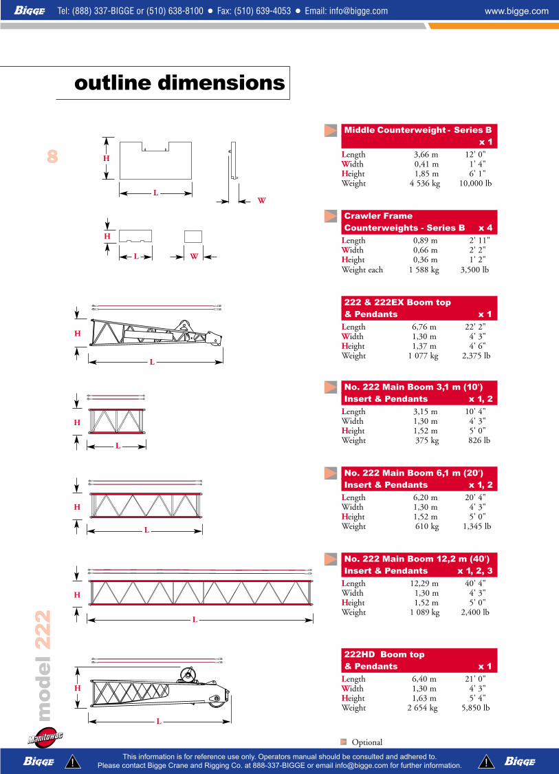
Middle Counterweight - Series B x 1
Length 3,66 m 12' 0"Width 0,41 m 1' 4"Height 1,85 m 6' 1" Weight 4 536 kg 10,000 lb
Crawler Frame Counterweights - Series B x 4
Length 0,89 m 2' 11"Width 0,66 m 2' 2"Height 0,36 m 1' 2"Weight each 1 588 kg 3,500 lb
222 & 222EX Boom top& Pendants x 1
Length 6,76 m 22' 2"Width 1,30 m 4' 3"Height 1,37 m 4' 6"Weight 1 077 kg 2,375 lb
No. 222 Main Boom 3,1 m (10')Insert & Pendants x 1, 2
Length 3,15 m 10' 4"Width 1,30 m 4' 3"Height 1,52 m 5' 0"Weight 375 kg 826 lb
No. 222 Main Boom 6,1 m (20')Insert & Pendants x 1, 2
Length 6,20 m 20' 4"Width 1,30 m 4' 3"Height 1,52 m 5' 0"Weight 610 kg 1,345 lb
No. 222 Main Boom 12,2 m (40')Insert & Pendants x 1, 2, 3
Length 12,29 m 40' 4"Width 1,30 m 4' 3"Height 1,52 m 5' 0"Weight 1 089 kg 2,400 lb
222HD Boom top& Pendants x 1
Length 6,40 m 21' 0"Width 1,30 m 4' 3"Height 1,63 m 5' 4"Weight 2 654 kg 5,850 lb
L W
H
L
L
L
H
H
H
Optional
L
H
L
H
W
L
H
outline dimensions
9
outline dimensions
mo
de
l2
22
Optional
L
H
L
H
L
H
L
L
L
H
H
H
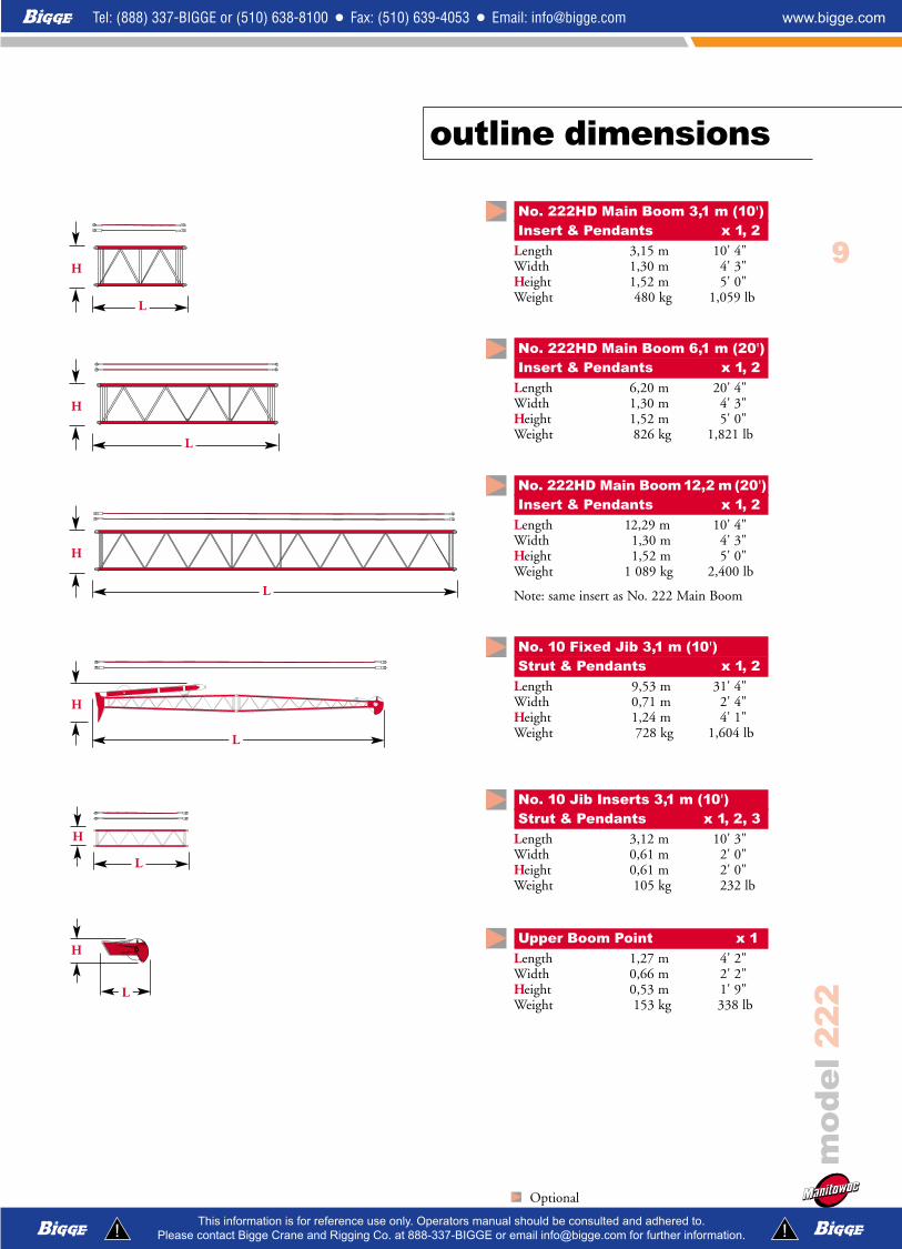
No. 222HD Main Boom 3,1 m (10')Insert & Pendants x 1, 2
Length 3,15 m 10' 4"Width 1,30 m 4' 3"Height 1,52 m 5' 0"Weight 480 kg 1,059 lb
No. 222HD Main Boom 6,1 m (20')Insert & Pendants x 1, 2
Length 6,20 m 20' 4"Width 1,30 m 4' 3"Height 1,52 m 5' 0"Weight 826 kg 1,821 lb
No. 222HD Main Boom 12,2 m (20')Insert & Pendants x 1, 2
Length 12,29 m 10' 4"Width 1,30 m 4' 3"Height 1,52 m 5' 0"Weight 1 089 kg 2,400 lb
Note: same insert as No. 222 Main Boom
No. 10 Fixed Jib 3,1 m (10')Strut & Pendants x 1, 2
Length 9,53 m 31' 4"Width 0,71 m 2' 4"Height 1,24 m 4' 1"Weight 728 kg 1,604 lb
No. 10 Jib Inserts 3,1 m (10')Strut & Pendants x 1, 2, 3
Length 3,12 m 10' 3"Width 0,61 m 2' 0"Height 0,61 m 2' 0"Weight 105 kg 232 lb
Upper Boom Point x 1 Length 1,27 m 4' 2"Width 0,66 m 2' 2"Height 0,53 m 1' 9"Weight 153 kg 338 lb

No. 260 Main Boom 8,8 m (29')Transition Insert & Pendants x 1
Length 8,99 m 29' 4"Width 1,93 m 6' 4"Height 2,59 m 8' 6"Weight 1 219 kg 2,687 lb
No. 260 Main Boom 3,1 m (10')Insert & Pendants x 1
Length 3,15 m 10' 4"Width 1,63 m 5' 4"Height 1,52 m 5' 0"Weight 411 kg 905 lb
No. 260 Main Boom 6,1 m (20')Insert & Pendants x 1, 2
Length 6,20 m 20' 4"Width 1,63 m 5' 4"Height 1,52 m 5' 0"Weight 674 kg 1,485 lb
No. 260 Main Boom 12,2 m (40')Insert & Pendants x 1
Length 12,29 m 40' 4"Width 1,63 m 5' 4"Height 1,52 m 5' 0"Weight 1 211 kg 2,670 lb
No. 260 Boom Cap 2,1 m (7') & No. 222 LuffingJibButt 5,8m (19')& Strut Assembly x 1
Length 8,05 m 26' 5"Width 1,63 m 5' 4"Height 2,54 m 8' 4"Weight 2 744 kg 6,050 lb
10
outline dimensions
mo
de
l2
22
L
H
Optional
L
L
L
L
H
H
H
H

11
outline dimensions
Optional
mo
de
l2
22
L
W
222, 222EX Hook block for 22,23 mm (7/8") wire ropeCapacity 91 mt 100 t Length 1,7 m 5' 7"Weight 1 121 kg 2,472 lb Width 0,6 m 2' 1"
Capacity 82 mt 90 t Length 1,5 m 5' 1"Weight 974 kg 2,148 lb Width 0,6 m 2' 1"
Capacity 54,4 mt 60 t Length 1,3 m 4' 4"Weight 636 kg 1,400 lb Width 0,6 m 2' 1"
Capacity 45,4 mt 50 t Length 1,3 m 4' 4"Weight 595 kg 1,310 lb Width 0,6 m 2' 1"
Capacity 36,3 mt 40 t Length 1,2 m 4' 1"Weight 590 kg 1,300 lb Width 0,6 m 2' 1"
Capacity 27,2 mt 30 t Length 1,1 m 3' 9"Weight 535 kg 1,178 lb Width 0,6 m 2'1"
222HD Hook block for 31,75 mm (1-1/4") wire ropeCapacity 91,0 mt 100 t Length 1,8 m 5' 11"Weight 1 978 kg 4,361 lb Width 0,9 m 3' 0"
Capacity 82,0 mt 90 t Length 1,8 m 5' 11"Weight 1 978 kg 4,361 lb Width 0,9 m 3' 0"
Capacity 36,3 mt 40 t Length 1,7 m 5' 6"Weight 1 495 kg 3,295 lb Width 0,9 m 2'11"
Capacity 32,0 mt 35 t Length 1,7 m 5' 6"Weight 1 495 kg 3,295 lb Width 0,9 m 2'11"
222 & 222EX Weight BallCapacity/Swivel 13,6 mt 12 t Diameter 0,5 m 1' 6"Weight 336 kg 740 lb Length 1,2 m 4' 0"
Capacity/Non-Swivel 13,6 mt 12 t Diameter 0,5 m 1' 6"Weight 336 kg 740 lb Length 1,2 m 4' 0"
222HD Weight BallCapacity/Swivel 17 mt 19 t Diameter 0,5 m 1' 6"Weight 340 kg 749 lb Length 1,2 m 4' 0"
L
W
L
D
12
mo
de
l2
22
Item
No. 222 Basic Cranewith Crawlers
Standard Outer Counterweight
Standard Inner Counterweight
Series B Middle Counterweight
SeriesB Crawler Frame Counterweight
12,2 m (40') No. 222Boom Insert, Pendants
6,1 m (20') No. 222Boom Insert, Pendants
3,0 m (10') No. 222Boom Insert, Pendants
Standard Boom Top5,9 m (19')
Upper Boom Point
9,1 m (30’) No. 10Fixed Jib Basic
3,0 m (10’) No. 10 JibInsert, Pendants
Hook Block 91,0 mton (100 ton)
Weight Ball
kg (lb)
42 102(92,818)
11 249(24,800)
12 927 (28,500)
4 536(10,000)
1 588 (3,500)
1 089(2,400)
610 (1,345)
375(826)
1 077 (2,375)
153(338)
728(1,604)
105(232)
1 121(2,472)
336(740)
1
1
1
1
1
43
71
2(9
6,3
68
)2
1
1
1
2
1
3
20
59
4
(45
,40
0)
3
1
3
1
1
1
1
20
84
2(4
5,9
46
)
Approximate Total Shipping Weight kg (lb)
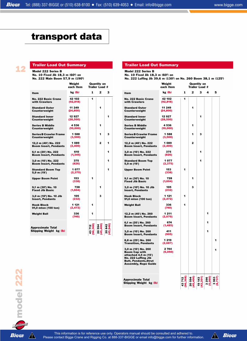
Trailer Load Out Summary
Model 222 Series B No. 10 Fixed Jib 18,3 m (60') onNo. 222 Main Boom 57,9 m (190')
Weight Quantity oneach Item Trailer Load #
transport data
Item
No. 222 Basic Cranewith Crawlers
Standard Outer Counterweight
Standard Inner Counterweight
Series B Middle Counterweight
SeriesB Crawler Frame Counterweight
12,2 m (40') No. 222Boom Insert, Pendants
3,0 m (10') No. 222Boom Insert, Pendants
Standard Boom Top5,9 m (19')
Upper Boom Point
9,1 m (30’) No. 10Fixed Jib Basic
3,0 m (10’) No. 10 JibInsert, Pendants
Hook Block 91,0 mton (100 ton)
Weight Ball
12,2 m (40') No. 260Boom Insert, Pendants
6,1 m (20') No. 260Boom Insert, Pendants
3,0 m (10') No. 260Boom Insert, Pendants
8,8 m (29') No. 260Transition, Pendants
3,0 m (10') No. 260Boom Cap withattached 4,5 m (15')No. 222 Luffing JibButt, Pendants,StrutAssembly, Rope Guide
kg (lb)
42 102(92,818)
11 249(24,800)
12 927 (28,500)
4 536(10,000)
1 588 (3,500)
1 089(2,400)
375(826)
1 077 (2,375)
153(338)
728(1,604)
105(232)
1 121(2,472)
336(740)
1 211(2,670)
674(1,485)
411(905)
1 219(2,687)
2 744(6,050)
1
1
1
1
1
Trailer Load #
43
71
2(9
6,3
68
)
2
1
1
1
2
1
32
0 5
94
(45
,40
0)
3
1
3
1
1
4
1
1
1
5
1
1
19
14
3(4
2,2
01
)
2 2
96
(5,0
60
)
3 9
63
(8,7
37
)
Approximate Total Shipping Weight kg (lb)
Trailer Load Out Summary
Model 222 Series B No. 10 Fixed Jib 18,3 m (60') on No. 222 Luffing Jib 39,6 m (130') on No. 260 Boom 38,1 m (125')
Weight Quantity oneach Item Trailer Load #

13
crane assembly
mo
de
l2
22
Fast Self Assembly
Three Trucks, Three People, Three HoursExtremely well designed and utilizing efficient use ofspace allows the Manitowoc Model 222 to be mobilizedwith only three people using three trucks in three hours -or less - with maximum boom, fixed jib andcounterweight.
mo
de
l2
22
14
Boom orBoom andFixed Jib
Length
m (ft)
12,2 (40)
15,2 (50)
18,3 (60)
21,3 (70)
24,4 (80)
27,4 (90)
30,5 (100)
33,5 (110)
36,6 (120)
39,6 (130)
42,7 (140)
45,7 (150)
48,8 (160)
51,8 (170)
54,9 (180)
57,9 (190)
61,0 (200)
64,0 (210)
67,1 (220)
70,1 (230)
73,2 (240)
76,2 (250)
performance data
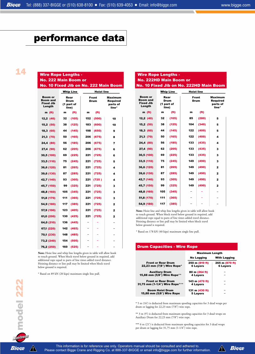
Wire Rope Lengths - No. 222 Main Boom orNo. 10 Fixed Jib on No. 222 Main Boom
Whip Line Hoist line
m
32
38
44
50
56
62
69
75
81
87
93
99
105
111
117
123
130
136
142
148
154
160
(ft)
(105)
(125)
(145)
(165)
(185)
(205)
(225)
(245)
(265)
(285)
(305)
(325)
(345)
(365)
(385)
(405)
(425)
(445)
(465)
(485)
(505)
(525)
m
152
183
198
206
206
206
221
221
221
221
221
221
221
221
221
221
221
–
–
–
–
–
(ft)
(500)
(600)
(650)
(675)
(675)
(675)
(725)
(725)
(725)
(725)
(725 )
(725)
(725)
(725)
(725)
(725)
(725)
–
–
–
–
–
MaximumRequiredparts of
line*
10
10
9
8
7
6
6
5
4
4
4
3
3
3
2
2
2
–
–
–
–
–
Rear Drum
(1 part ofline)
Front Drum
Front or Rear Drum 22,23 mm (7/8") Wire Rope*
Auxiliary Drum15,88 mm (5/8") Wire Rope**
Front or Rear Drum31,75 mm (1-1/4") Wire Rope***
Boom Hoist Drum15,88 mm (5/8") Wire Rope
250 m (819 ft)6 Layers
80 m (264 ft)4 Layers
143 m (470 ft)4 Layers
131 m (430 ft)5 Layers
265 m (870 ft)6 Layers
––
––
––
Drum Capacities - Wire Rope
Maximum Length
No Lagging With Lagging
Note: Hoist line and whip line lengths given in table will allow hookto touch ground. When block travel below ground in required, addadditional rope equal to parts of line times added travel distance.Hoisting distance or line pull may be limited when block travelbelow ground is required.
* Based on 89 kN (20 kips) maximum single line pull.
* 5 m (16') is deducted from maximum spooling capacities for 3 dead wraps perdrum or lagging for 22,23 mm (7/8") wire rope.
** 3 m (9') is deducted from maximum spooling capacities for 3 dead wraps onAuxiliary Drum for 22,23 mm (7/8") wire rope.
*** 6 m (21') is deducted from maximum spooling capacities for 3 dead wrapsper drum or lagging for 31,75 mm (1-1/4") wire rope.
Boom orBoom andFixed Jib
Length
m (ft)
12,2 (40)
15,2 (50)
18,3 (60)
21,3 (70)
24,4 (80)
27,4 (90)
30,5 (100)
33,5 (110)
36,6 (120)
39,6 (130)
42,7 (140)
45,7 (150)
48,8 (160)
51,8 (170)
54,9 (180)
Wire Rope Lengths - No. 222HD Main Boom or
No. 10 Fixed Jib on No. 222HD Main BoomWhip Line Hoist line
m
32
38
44
50
56
62
69
75
81
87
93
99
105
111
117
(ft)
(105)
(125)
(145)
(165)
(185)
(205)
(225)
(245)
(265)
(285)
(305)
(325)
(345)
(365)
(385)
m
85
104
122
122
133
133
133
149
149
149
149
149
–
–
–
(ft)
(280)
(340)
(400)
(400)
(435)
(435)
(435)
(490)
(490)
(490)
(490)
(490)
–
–
–
MaximumRequiredparts of
line*
5
5
5
4
4
3
3
3
2
2
2
2
–
–
–
Rear Drum
(1 part ofline)
Front Drum
Note: Hoist line and whip line lengths given in table will allow hookto touch ground. When block travel below ground in required, addadditional rope equal to parts of line times added travel distance.Hoisting distance or line pull may be limited when block travelbelow ground is required.
* Based on 178 kN (40 kips) maximum single line pull.
mo
de
l2
22
15
performance data
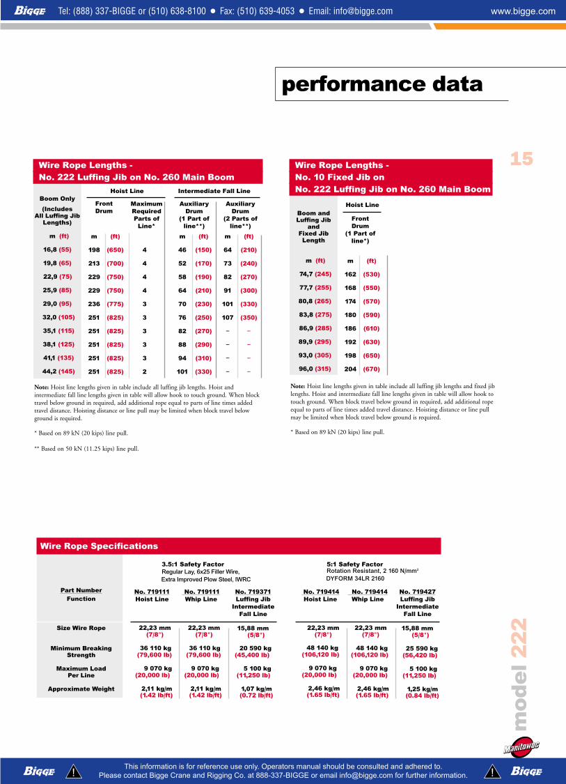
Part NumberFunction
Size Wire Rope
Minimum BreakingStrength
Maximum LoadPer Line
Approximate Weight
No. 719111Hoist Line
22,23 mm(7/8")
36 110 kg(79,600 lb)
9 070 kg(20,000 lb)
2,11 kg/m (1.42 lb/ft)
No. 719111Whip Line
22,23 mm(7/8")
36 110 kg(79,600 lb)
9 070 kg(20,000 lb)
2,11 kg/m (1.42 lb/ft)
No. 719414Hoist Line
22,23 mm(7/8")
48 140 kg(106,120 lb)
9 070 kg(20,000 lb)
2,46 kg/m (1.65 lb/ft)
No. 719414Whip Line
22,23 mm(7/8")
48 140 kg(106,120 lb)
9 070 kg(20,000 lb)
2,46 kg/m (1.65 lb/ft)
3.5:1 Safety FactorRegular Lay, 6x25 Filler Wire,Extra Improved Plow Steel, IWRC
Wire Rope Specifications
No. 719371Luffing Jib
IntermediateFall Line
15,88 mm(5/8")
20 590 kg(45,400 lb)
5 100 kg(11,250 lb)
1,07 kg/m (0.72 lb/ft)
No. 719427Luffing Jib
IntermediateFall Line
15,88 mm(5/8")
25 590 kg(56,420 lb)
5 100 kg(11,250 lb)
1,25 kg/m (0.84 lb/ft)
5:1 Safety Factor Rotation Resistant, 2 160 N/mm2
DYFORM 34LR 2160
Boom Only
(IncludesAll Luffing Jib
Lengths)
m (ft)
16,8 (55)
19,8 (65)
22,9 (75)
25,9 (85)
29,0 (95)
32,0 (105)
35,1 (115)
38,1 (125)
41,1 (135)
44,2 (145)
Wire Rope Lengths -No. 222 Luffing Jib on No. 260 Main Boom
Hoist Line Intermediate Fall Line
m
198
213
229
229
236
251
251
251
251
251
(ft)
(650)
(700)
(750)
(750)
(775)
(825)
(825)
(825)
(825)
(825)
m
46
52
58
64
70
76
82
88
94
101
(ft)
(150)
(170)
(190)
(210)
(230)
(250)
(270)
(290)
(310)
(330)
Front Drum
AuxiliaryDrum
(1 Part ofline**)
m
64
73
82
91
101
107
–
–
–
–
(ft)
(210)
(240)
(270)
(300)
(330)
(350)
–
–
–
–
AuxiliaryDrum
(2 Parts ofline**)
4
4
4
4
3
3
3
3
3
2
MaximumRequiredParts of
Line*
Note: Hoist line lengths given in table include all luffing jib lengths. Hoist andintermediate fall line lengths given in table will allow hook to touch ground. When blocktravel below ground in required, add additional rope equal to parts of line times addedtravel distance. Hoisting distance or line pull may be limited when block travel belowground is required.
* Based on 89 kN (20 kips) line pull.
** Based on 50 kN (11.25 kips) line pull.
Boom andLuffing Jib
andFixed Jib
Length
m (ft)
74,7 (245)
77,7 (255)
80,8 (265)
83,8 (275)
86,9 (285)
89,9 (295)
93,0 (305)
96,0 (315)
Wire Rope Lengths - No. 10 Fixed Jib onNo. 222 Luffing Jib on No. 260 Main Boom
Hoist Line
m
162
168
174
180
186
192
198
204
(ft)
(530)
(550)
(570)
(590)
(610)
(630)
(650)
(670)
Front Drum
(1 Part ofline*)
Note: Hoist line lengths given in table include all luffing jib lengths and fixed jiblengths. Hoist and intermediate fall line lengths given in table will allow hook totouch ground. When block travel below ground in required, add additional ropeequal to parts of line times added travel distance. Hoisting distance or line pullmay be limited when block travel below ground is required.
* Based on 89 kN (20 kips) line pull.

8
80(261)
78 (255)
74 (243)
4
57(188)
57 (186)
55 (180)
52 (172)
2
46(151)
46 (150
45 (148)
44 (143)
42(137)
1
41 (133)
41(132)
40(130)
39 (127)
37(122)
36(117)
3
52(170)
51 (168
50 (164)
48 (157)
46(150)
6
69(225)
67 (221)
65 (213)
60 (197)
5
63 (206)
62(203)
60(196)
56 (185)
7
74(243)
73 (239)
69 (228)
9
85(280)
83 (273)
79 (258)
mo
de
l2
22
16
Layer
Line Pullkg (lb)
0)(0)
2 268)(5,000)
4 536)(10,000)
6 803)(15,000)
9 072)(20,000)
6
174(570)
157(515)
123 (404)
90 (296)
74 (242)
5
163(535)
148 (487)
122 (399)
89 (291)
72 (237)
4
152(500)
140 (458)
120 (394)
87 (286)
71 (232)
2
131(430)
122 (399)
112 (368)
84 (276)
68 (223)
1
121(395)
113(369)
105(343)
83 (272)
66(218)
3
142(465)
131 (429)
119 (389)
86 (281)
69 (227)
Hoist Drum - 89 kN (20 kips) Full Power Drum - Continuous DutySingle Line Pull/Single Line Speed
m/min (ft/min)
Layer
Line Pullkg (lb)
0)(0)
2 268)(5,000)
4 536)(10,000)
6 803)(15,000)
4
77(252)
75 (245)
71 (232)
2
66(215)
64 (209)
62 (204)
1
60 (196)
59(191)
57(188)
54 (176)
3
71(234)
70 (228)
66 (218)
Auxiliary Drum - 66,7 kN (15 kips)Full Power Drum - Continuous DutySingle Line Pull/Single Line Speed
m/min (ft/min)
Layer
Line Pullkg (lb)
0)(0)
4 536)(10,000)
9 072)(20,000)
13 608)(30,000)
18 144)(40,000)
4
81(266)
75 (245)
68 (222)
51 (167)
42 (139)
2
69(227)
65 (212)
60 (196)
48 (158)
40 (131)
1
63(207)
59(195)
55(182)
47 (154)
39(127)
3
75(246)
69 (228)
64 (210)
49 (162)
41 (135)
Hoist Drum - 178 kN (40 kips) Full Power Drum - Continuous DutySingle Line Pull/Single Line Speed
m/min (ft/min)
Layer
Line Pullkg (lb)
0)(0)
2 268)(5,000)
4 536)(10,000)
6 803)(15,000)
9 072)(20,000)
11 340)(25,000)
Auxiliary Drum - 111 kN (25 kips)Full Power Drum - Continuous DutySingle Line Pull/Single Line Speed
m/min (ft/min)
performance data
NOTE: Line pull is infinitely variable.NOTE: Line pull is infinitely variable.
NOTE: Line pull is infinitely variable.
NOTE: Line pull is infinitely variable.

Main Boom
61,0(200)
57,9(190)
61,0(200)
57,9(190)
54,9(180)
51,8(170)
57,9(190)
54,9(180)
51,8(170)
48,8 (160)
MethodOver
end ofblockedcrawlers
m(ft)
FixedJib
––
18,3(60)
––
18,3 (60)
––
––
––
––
15,2(50)
18,3 (60)
Fixed Jib
––
18,3(60)
––
––
12,2 (40)
18,3 (60)
––
––
––
––
15,2 (50)
18,3 (60)
Maximum Length – Unassisted RaisingNo. 10 Fixed Jib on No. 222 Main Boom
222, 222EX 222, 222EX Series B
Over side of
extendedcrawlers
m(ft)
Over side of
retractedcrawlers
m(ft)
Main Boom
61,0(200)
57,9(190)
61,0(200)
57,9(190)
54,9(180)
51,8(170)
––
––
51,8(170)
48,8 (160)
45,7(150)
42,7 (140)
NOTE: Load block(s), hook(s) and weight ball(s) on ground at start.
mo
de
l2
22
17
performance data
Configuration
12,2 m (40')No. 222 Main Boom
57,9 m (190')No. 222 Main Boomcombined with18,3 m (60')No. 10 Fixed Jib
68 965(152,043)
74 260(163,714)
79 853(176,043)
85 148(187,714)
Working Weight
kg (lb)222 Series B 222
Typical working weight consists of: hydraulic reservoirs full, fuel half-full,drums loaded with standard lengths of wire rope, upper boom point, 91 mt(100 t) hook block, and standard weight ball.
Note: Upper boom point not used with fixed jib.
Method
Overend of
blockedcrawlers
m(ft)
Main Boom
16,8(55)
19,8(65)
22,9(75)
25,9(85)
29,0(95)
32,0(105)
––
––
––
––
Luffing Jib
15,2 - 36,6(50 - 120)
15,2 - 33,5(50 - 110)
15,2 - 30,5(50 - 100)
15,2 - 24,4(50 - 80)
15,2 - 21,3(50 - 70)
15,2 - 18,3(50 - 60)
––
––
––
––
Main Boom
16,8(55)
19,8(65)
22,9(75)
25,9(85)
29,0(95)
32,0(105)
35,1(115)
38,1(125)
41,1(135)
44,2(145)
Luffing Jib
39,6 - 45,7(130 - 150)
36,6 - 45,7(120 - 150)
33,5 - 45,7(110 - 150)
27,4 - 45,7(90 - 150)
24,4 - 45,7(80 - 150)
21,3 - 45,7(70 - 150)
15,2 - 45,7(50 - 150)
15,2 - 42,7(50 - 140)
15,2 - 30,5(50 - 100)
18,3(60)
Maximum Length – Unassisted RaisingNo. 222 Luffing Jib on No. 260 Main Boom
222, 222EXSeries B
In-Line Procedure Jack-Knife Procedure
NOTE: Load block(s), hook(s) and weight ball(s) on ground at start.
Method
Overend of
blockedcrawlers
m(ft)
Main Boom
35,1(115)
38,1(125)
41,1(135)
Fixed Jib
9,1 - 18,3(30 - 60)
9,1 - 18,3(30 - 60)
9,1 - 18,3(30 - 60)
Luffing Jib
30,5 - 39,6(100 - 130)
30,5 - 39,6(100 - 130)
30,5(100)
Maximum Length – Unassisted RaisingNo. 10 Fixed Jib on No. 222 Luffing Jib on No. 260 Main Boom
222, 222EXSeries B
Jack-Knife Procedure
NOTE: Load block(s), hook(s) and weight ball(s) on ground at start.

222
Model 222 Series B No. 10 Fixed Jib onNo. 222 Main Boom
76,2 m (250 ft)
3,0 m (10 ft)No. 10 Jib Insert
4,6 m (15 ft)No. 10 Jib Top
4,6 m (15 ft)No. 10 Jib Butt
No. 10 Fixed Jib18,3 m (60 ft)
5,8 m (19 ft)No. 222 Boom Butt
12,2 m (40 ft)No. 222 Boom Insert
6,1 m (20 ft)No. 222 Boom Insert
3,0 m (10 ft)No. 222 Boom Insert
12,2 m (40 ft)No. 222 Boom Insert
12,2 m (40 ft)No. 222 Boom Insert
6,4 m (21 ft)No. 222 Boom Top
No. 222, 222EXMain Boom
57,9 m (190 ft)
mo
de
l2
22
222
18
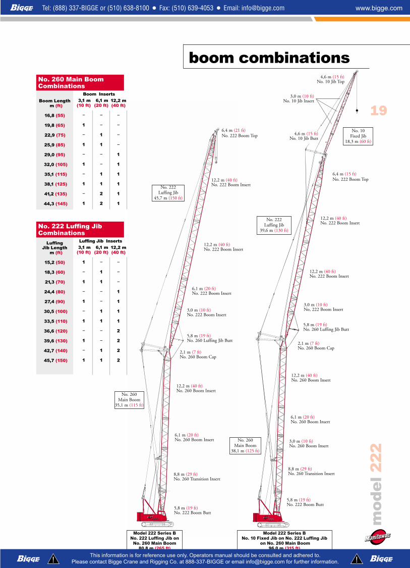
boom combinations
Boom Lengthm (ft)
12,2 (40)
15,2 (50)
18,3 (60)
21,3 (70)
24,4 (80)
27,4 (90)
30,5 (100)
33,5 (110)
36,6 (120)
39,6 (130)
42,7 (140)
45,7 (150)
48,8 (160)
51,8 (170)
54,9 (180)
57,9 (190)
61,0 (200)
3,1 m(10 ft)
–
1
–
1
–
1
–
1
–
1
–
1
–
1
–
1
2
6,1 m(20 ft)
–
–
1
1
–
–
1
1
–
–
1
1
–
–
1
1
1
12,2 m(40 ft)
–
–
–
–
1
1
1
1
2
2
2
2
3
3
3
3
3
No. 222 Heavy-Lift Boom Combinations
Boom Inserts
Jib Lengthm (ft)
9,1 (30)
12,2 (40)
15,2 (50)
18,3 (60)
3,1m(10 ft)
–
1
2
3
No. 10 Fixed Jib Combinations
Boom Lengthm (ft)
12,2 (40)
15,2 (50)
18,3 (60)
21,3 (70)
24,4 (80)
27,4 (90)
30,5 (100)
33,5 (110)
36,6 (120)
39,6 (130)
42,7 (140)
45,7 (150)
3,1 m(10 ft)
–
1
–
1
–
1
–
1
–
1
–
1
6,1 m(20 ft)
–
–
1
1
–
–
1
1
–
–
1
1
12,2 m*(40 ft)
–
–
–
–
1
1
1
1
2
2
2
2
No. 222HD Heavy-DutyBoom Combinations
Boom Inserts
Model 222 Series B No. 222 Main Boom
61,0 m (200 ft)
Model 222 Series B No. 222HD Main Boom
45,7 m (150 ft)
5,8 m (19 ft)No. 222 Boom Butt
5,8 m (19 ft)No. 222HD Boom Butt
12,2 m (40 ft)No. 222 Boom Insert
6,1 m (20 ft)No. 222HD Boom Insert
3,0 m (10 ft)No. 222HD Boom Insert
12,2 m (40 ft)No. 222 Boom Insert
6,1 m (20 ft)No. 222 Boom Insert
3,0 m (10 ft)No. 222 Boom Insert
12,2 m (40 ft)No. 222 Boom Insert
12,2 m (40 ft)No. 222 Boom Insert
6,4 m (21 ft)No, 222HD Boom Top
6,4 m (21 ft)No. 222 Boom Top
No. 222HDMain Boom
45,7 m (150 ft)
12,2 m (40 ft)No. 222 Boom Insert
No. 222, 222EXMain Boom
61,0 m (200 ft)
Fixed Jib Inserts
*12,2 m (40') insert same as No. 222 Main Boom.
222 222222
Drawing 260 125 130 60
19
mo
de
l2
22
boom combinations
No. 10Fixed Jib
18,3 m (60 ft)
12,2 m (40 ft)No. 260 Boom Insert
6,1 m (20 ft)No. 260 Boom Insert
12,2 m (40 ft)No. 260 Boom Insert
3,0 m (10 ft)No. 10 Jib Insert
4,6 m (15 ft)No. 10 Jib Top
4,6 m (15 ft)No. 10 Jib Butt
2,1 m (7 ft)No. 260 Boom Cap
5,8 m (19 ft)No. 222 Boom Butt
No. 222Luffing Jib
45,7 m (150 ft)
Boom Lengthm (ft)
16,8 (55)
19,8 (65)
22,9 (75)
25,9 (85)
29,0 (95)
32,0 (105)
35,1 (115)
38,1 (125)
41,2 (135)
44,3 (145)
3,1 m(10 ft)
–
1
–
1
–
1
–
1
–
1
6,1 m(20 ft)
–
–
1
1
–
–
1
1
2
2
12,2 m(40 ft)
–
–
–
–
1
1
1
1
1
1
No. 260 Main BoomCombinations
Boom Inserts
LuffingJib Length
m (ft)
15,2 (50)
18,3 (60)
21,3 (70)
24,4 (80)
27,4 (90)
30,5 (100)
33,5 (110)
36,6 (120)
39,6 (130)
42,7 (140)
45,7 (150)
3,1 m(10 ft)
1
–
1
–
1
–
1
–
1
–
1
6,1 m(20 ft)
–
1
1
–
–
1
1
–
–
1
1
12,2 m(40 ft)
–
–
–
1
1
1
1
2
2
2
2
No. 222 Luffing JibCombinations
Luffing Jib Inserts
Model 222 Series B No. 222 Luffing Jib on
No. 260 Main Boom80,8 m (265 ft)
Model 222 Series B No. 10 Fixed Jib on No. 222 Luffing Jib
on No. 260 Main Boom96,0 m (315 ft)
No. 222Luffing Jib
39,6 m (130 ft)
5,8 m (19 ft)No. 222 Boom Butt
6,1 m (20 ft)No. 260 Boom Insert
8,8 m (29 ft)No. 260 Transition Insert
12,2 m (40 ft)No. 222 Boom Insert
6,1 m (20 ft)No. 222 Boom Insert
3,0 m (10 ft)No. 222 Boom Insert
8,8 m (29 ft)No. 260 Transition Insert
2,1 m (7 ft)No. 260 Boom Cap
3,0 m (10 ft)No. 260 Boom Insert
12,2 m (40 ft)No. 222 Boom Insert
5,8 m (19 ft)No. 260 Luffing Jib Butt
3,0 m (10 ft)No, 222 Boom Insert
5,8 m (19 ft)No. 260 Luffing Jib Butt
12,2 m (40 ft)No. 222 Boom Insert
12,2 m (40 ft)No. 222 Boom Insert
No. 260Main Boom
35,1 m (115 ft)
No. 260Main Boom
38,1 m (125 ft)
6,4 m (21 ft)No. 222 Boom Top
6,4 m (15 ft)No. 222 Boom Top

61,0(200)
(40) 12,2
(50) 15,2
(200) 61,0
(190) 57,9
(180) 54,9
(170) 51,8
(160) 48,8
(150) 45,7
(140) 42,7
(130) 39,6
(120) 36,6
(110) 33,5
(100) 30,5
(90) 27,4
(80) 24,4
(70) 21,3
(60) 18,3
(30) 9,1
45,7(150)
42,7(140)
39,6(130)
36,6(120)
33,5(110)
30,5(100)
27,4(90)
24,4(80)
21,3(70)
18,3(60)
15,2(50)
12,2(40)
9,1(30)
DISTANCE FROM CENTERLINE ROTATION m (ft)
57,9(190)
48,8(160)
39,6(130)
30,5(100)
27,4(90)
21,3(70)
18,3(60)
15,2(50)
12,2(40)
24,4(80)
33,5(110)
36,6(120)
42,7(140)
45,7(150)
54,9(180)
51,8(170)
0,97 m (3' 2")(14' 7")
4,43 m
TAILSWINGSERIES B
1,66 m5' 6"
60 ̊
50 ̊
40 ̊
30 ̊
80 ̊
70 ̊
ROTATION
HE
IGH
T A
BO
VE
GR
OU
ND
m (f
t)
82 ̊
20 ̊
(210) 64,0
48,8(160)
No. 222 Main Boom
heavy-lift boom range diagram
20
mo
de
l2
22
mo
de
l2
22
21
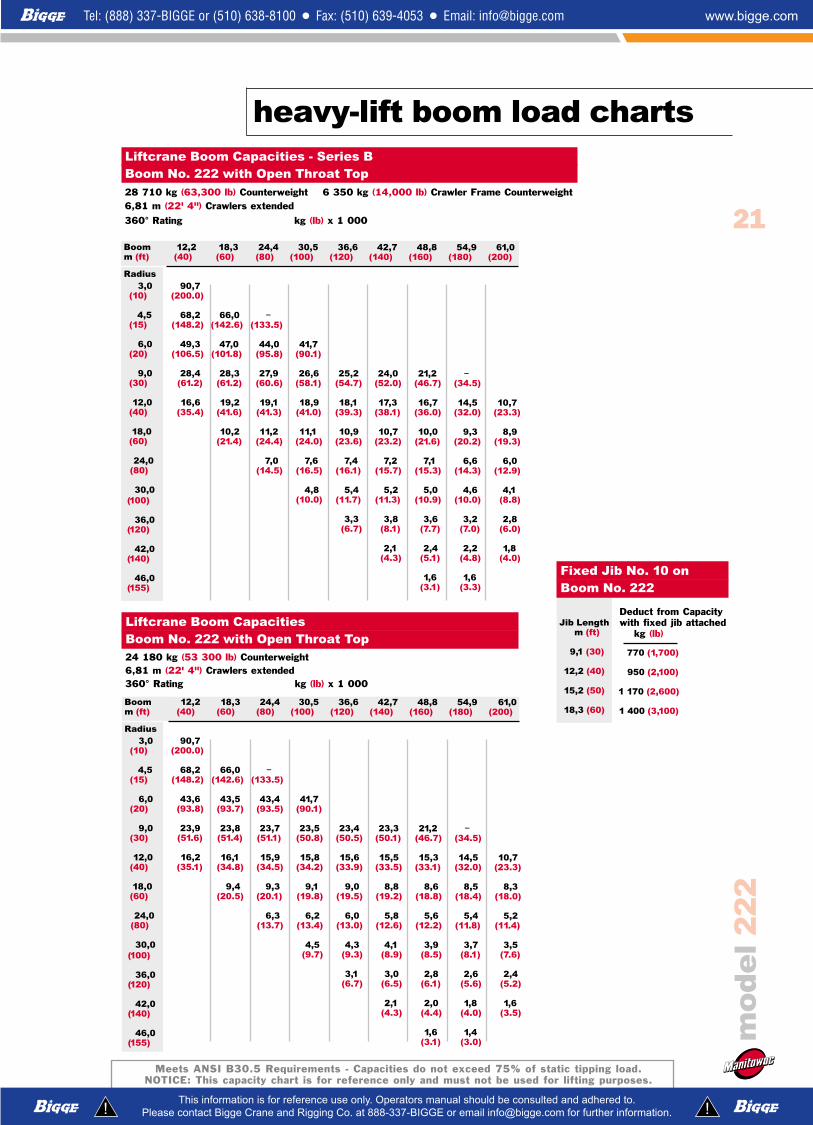
heavy-lift boom load charts
Meets ANSI B30.5 Requirements - Capacities do not exceed 75% of static tipping load.NOTICE: This capacity chart is for reference only and must not be used for lifting purposes.
Boomm (ft)
Radius 3,0
(10)
4,5(15)
6,0(20)
9,0(30)
12,0(40)
18,0(60)
24,0(80)
30,0(100)
36,0(120)
42,0(140)
46,0(155)
12,2(40)
90,7(200.0)
68,2(148.2)
49,3(106.5)
28,4(61.2)
16,6(35.4)
18,3(60)
66,0(142.6)
47,0(101.8)
28,3(61.2)
19,2(41.6)
10,2(21.4)
24,4(80)
–(133.5)
44,0(95.8)
27,9(60.6)
19,1(41.3)
11,2(24.4)
7,0(14.5)
30,5(100)
41,7(90.1)
26,6(58.1)
18,9(41.0)
11,1(24.0)
7,6(16.5)
4,8(10.0)
36,6(120)
25,2(54.7)
18,1(39.3)
10,9(23.6)
7,4(16.1)
5,4(11.7)
3,3(6.7)
42,7(140)
24,0(52.0)
17,3(38.1)
10,7(23.2)
7,2(15.7)
5,2(11.3)
3,8(8.1)
2,1(4.3)
48,8(160)
21,2(46.7)
16,7(36.0)
10,0(21.6)
7,1(15.3)
5,0(10.9)
3,6(7.7)
2,4(5.1)
1,6(3.1)
54,9(180)
–(34.5)
14,5(32.0)
9,3(20.2)
6,6(14.3)
4,6(10.0)
3,2(7.0)
2,2(4.8)
1,6(3.3)
61,0(200)
10,7(23.3)
8,9(19.3)
6,0(12.9)
4,1(8.8)
2,8(6.0)
1,8(4.0)
Liftcrane Boom Capacities - Series BBoom No. 222 with Open Throat Top28 710 kg (63,300 lb) Counterweight 6 350 kg (14,000 lb) Crawler Frame Counterweight6,81 m (22' 4") Crawlers extended
360° Rating kg (lb) x 1 000
Boomm (ft)
Radius 3,0
(10)
4,5(15)
6,0(20)
9,0(30)
12,0(40)
18,0(60)
24,0(80)
30,0(100)
36,0(120)
42,0(140)
46,0(155)
12,2(40)
90,7(200.0)
68,2(148.2)
43,6(93.8)
23,9(51.6)
16,2(35.1)
18,3(60)
66,0(142.6)
43,5(93.7)
23,8(51.4)
16,1(34.8)
9,4(20.5)
24,4(80)
–(133.5)
43,4(93.5)
23,7(51.1)
15,9(34.5)
9,3(20.1)
6,3(13.7)
30,5(100)
41,7(90.1)
23,5(50.8)
15,8(34.2)
9,1(19.8)
6,2(13.4)
4,5(9.7)
36,6(120)
23,4(50.5)
15,6(33.9)
9,0(19.5)
6,0(13.0)
4,3(9.3)
3,1(6.7)
42,7(140)
23,3(50.1)
15,5(33.5)
8,8(19.2)
5,8(12.6)
4,1(8.9)
3,0(6.5)
2,1(4.3)
48,8(160)
21,2(46.7)
15,3(33.1)
8,6(18.8)
5,6(12.2)
3,9(8.5)
2,8(6.1)
2,0(4.4)
1,6(3.1)
54,9(180)
–(34.5)
14,5(32.0)
8,5(18.4)
5,4(11.8)
3,7(8.1)
2,6(5.6)
1,8(4.0)
1,4(3.0)
61,0(200)
10,7(23.3)
8,3(18.0)
5,2(11.4)
3,5(7.6)
2,4(5.2)
1,6(3.5)
Liftcrane Boom CapacitiesBoom No. 222 with Open Throat Top24 180 kg (53 300 lb) Counterweight 6,81 m (22' 4") Crawlers extended 360° Rating kg (lb) x 1 000
Jib Lengthm (ft)
9,1 (30)
12,2 (40)
15,2 (50)
18,3 (60)
770 (1,700)
950 (2,100)
1 170 (2,600)
1 400 (3,100)
Fixed Jib No. 10 on Boom No. 222
Deduct from Capacitywith fixed jib attached
kg (lb)

heavy-duty boom range diagram
22
mo
de
l2
22
222
45,7(150)
(40) 12,2
(50) 15,2
(200) 61,0
(190) 57,9
(180) 54,9
(170) 51,8
(160) 48,8
(150) 45,7
(140) 42,7
(130) 39,6
(120) 36,6
(110) 33,5
(100) 30,5
(90) 27,4
(80) 24,4
(70) 21,3
(60) 18,3
(30) 9,1
45,7(150)
42,7(140)
39,6(130)
36,6(120)
33,5(110)
30,5(100)
27,4(90)
24,4(80)
21,3(70)
18,3(60)
15,2(50)
12,2(40)
9,1(30)
DISTANCE FROM CENTERLINE ROTATION m (ft)
39,6(130)
30,5(100)
27,4(90)
21,3(70)
18,3(60)
15,2(50)
12,2(40)
24,4(80)
33,5(110)
36,6(120)
42,7(140)
0,97 m (3' 2")(14' 7")
4,43 m
TAILSWINGSERIES B
1,66 m5' 6"
60 ̊
50 ̊
40 ̊
30 ̊
80 ̊
70 ̊
ROTATION
HE
IGH
T A
BO
VE
GR
OU
ND
m (f
t)
81.9 ̊
20 ̊
(210) 64,0
45,7(150)
No. 222HD Main Boom

Meets ANSI B30.5 Requirements - Capacities do not exceed 75% of static tipping load.NOTICE: This capacity chart is for reference only and must not be used for lifting purposes.
23Boomm (ft)
Radius 3,0
(10)
4,0(13)
4,5(15)
6,0(20)
9,0(30)
12,0(40)
18,0(60)
24,0(80)
30,0(100)
36,0(120)
38,0(125)
12,2(40)
90,7(200.0)
76,8(171.0)
68,2(148.2)
50,7(109.2)
27,4(59.1)
16,4(34.3)
18,3(60)
77,4(170.7)
67,5(145.8)
47,5(102.7)
27,1(58.6)
18,0(38.9)
8,7(18.1)
24,4(80)
43,8(94.6)
27,0(58.1)
17,8(38.5)
9,8(21.3)
4,9(10.1)
30,5(100)
41,0(88.5)
25,2(54.6)
17,5(38.0)
9,6(20.8)
6,0(13.0)
2,6(5.2)
36,6(120)
23,9(51.6)
17,4(38.0)
9,6(20.7)
6,0(13.0)
3,6(7.6)
42,7(140)
22,5(48.6)
16,9(36.1)
9,1(19.6)
5,5(11.8)
3,3(7.0)
1,7(3.4)
45,7(150)
22,1(47.8)
16,6(35.5)
8,9(19.2)
5,4(11.7)
3,3(7.1)
1,8(3.7)
1,3(3.0)
Liftcrane Boom Capacities - Series BBoom No. 222HD with Open Throat Top28 710 kg (63,300 lb) Counterweight 6 350 kg (14,000 lb) Crawler Frame Counterweight6,81 m (22' 4") Crawlers extended
360° Rating kg (lb) x 1 000
Boomm (ft)
Radius 3,0
(10)
4,0(13)
4,5(15)
6,0(20)
9,0(30)
12,0(40)
18,0(60)
24,0(80)
30,0(100)
36,0(120)
12,2(40)
90,7(200.0)
75,9(169.0)
67,9(147.4)
42,7(91.8)
22,8(49.3)
15,1(32.6)
18,3(60)
75,8(167.2)
67,1(145.8)
42,6(91.5)
22,6(48.8)
14,9(32.1)
8,1(17.6)
24,4(80)
42,4(91.1)
22,4(48.3)
14,7(31.7)
7,9(17.1)
4,7(10.1)
30,5(100)
41,0(88.5)
22,2(47.8)
14,4(31.2)
7,7(16.6)
4,6(10.0)
2,6(5.2)
36,6(120)
22,1(47.7)
14,4(31.1)
7,6(16.5)
4,6(9.9)
2,8(6.1)
42,7(140)
21,9(47.2)
14,2(30.6)
7,4(15.9)
4,3(9.3)
2,6(5.6)
1,5(3.2)
45,7(150)
22,0(47.3)
14,2(30.7)
7,4(16.0)
4,4(9.4)
2,6(5.7)
1,5(3.3)
Liftcrane Boom Capacities Boom No. 222HD with Open Throat Top24 180 kg (53,300 lb) Counterweight 6,81 m (22' 4") Crawlers extended
360° Rating kg (lb) x 1 000
heavy-duty boom load charts
mo
de
l2
22
Jib Lengthm (ft)
9,1 (30)
12,2 (40)
15,2 (50)
18,3 (60)
770 (1,700)
950 (2,100)
1 170 (2,600)
1 400 (3,100)
Fixed Jib No. 10 on Boom No. 222HD
Deduct from Capacitywith fixed jib attached
kg (lb)
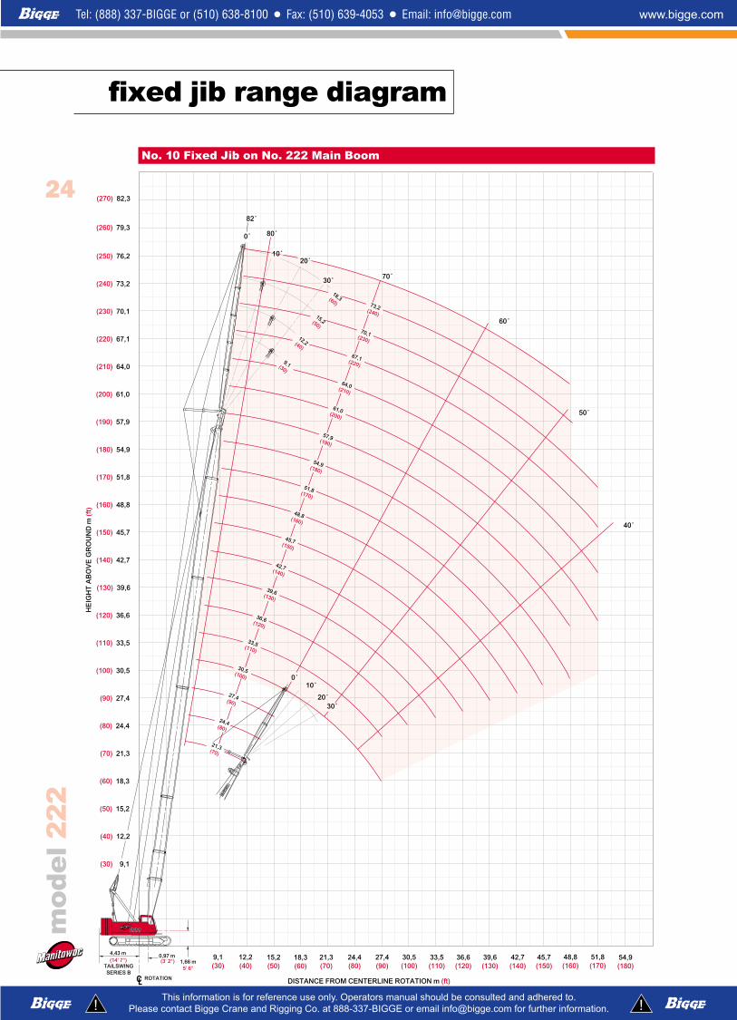
fixed jib range diagramm
od
el
22
2
10 ̊
20 ̊
0 ̊
30 ̊
222222
61,0(200)
64,0(210)
67,1(220)
70,1(230)
73,2(240)
9,1(30)
12,2(40)
15,2(50)
18,3(60)
(40) 12,2
(50) 15,2
(250) 76,2
(260) 79,3
(240) 73,2
(230) 70,1
(220) 67,1
(210) 64,0
(200) 61,0
(190) 57,9
(180) 54,9
(170) 51,8
(160) 48,8
(150) 45,7
(140) 42,7
(130) 39,6
(120) 36,6
(110) 33,5
(100) 30,5
(90) 27,4
(80) 24,4
(70) 21,3
(60) 18,3
(30) 9,1
45,7(150)
42,7(140)
39,6(130)
36,6(120)
33,5(110)
30,5(100)
27,4(90)
24,4(80)
21,3(70)
18,3(60)
15,2(50)
12,2(40)
9,1(30)
DISTANCE FROM CENTERLINE ROTATION m (ft)
57,9(190)
48,8(160)
39,6(130)
30,5(100)
27,4(90)
21,3(70)
24,4(80)
33,5(110)
36,6(120)
42,7(140)
45,7(150)
54,9(180)
51,8(170)
0,97 m (3' 2")(14' 7")
4,43 m
TAILSWINGSERIES B
1,66 m5' 6"
60 ̊
50 ̊
40 ̊
80 ̊
10 ̊
30 ̊ 70 ̊
ROTATION
HE
IGH
T A
BO
VE
GR
OU
ND
m (f
t)
82 ̊
0 ̊
51,8(170)
48,8(160)
(270) 82,3
20 ̊
54,9(180)
No. 10 Fixed Jib on No. 222 Main Boom
24
mo
de
l2
22
25
fixed jib load charts
Meets ANSI B30.5 Requirements - Capacities do not exceed 75% of static tipping load.NOTICE: This capacity chart is for reference only and must not be used for lifting purposes.
Jib
Leng
th9
,1 m
(3
0 f
t)
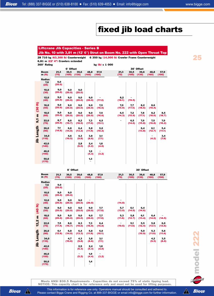
Liftcrane Jib Capacities - Series BJib No. 10 with 3,81 m (12' 6") Strut on Boom No. 222 with Open Throat Top
28 710 kg (63,300 lb) Counterweight 6 350 kg (14,000 lb) Crawler Frame Counterweight6,81 m (22' 4") Crawlers extended 360° Rating kg (lb) x 1 000
0˚ Offset 30˚ Offset
21,3(70)
9,0(20.0)
9,0(20.0)
9,0(20.0)
9,0(20.0)
9,0(20.0)
7,5(17.4)
6,1(12.8)
30,5(100)
9,0(20.0)
9,0(20.0)
9,0(20.0)
9,0(20.0)
8,6(19.7)
6,8(14.0)
4,7(10.6)
39,6(130)
9,0(20.0)
9,0(20.0)
9,0(20.0)
8,3(19.0)
6,4(13.3)
4,3(9.8)
2,9(6.3)
–(5.2)
48,8(160)
–(20.0)
9,0(20.0)
9,0(20.0)
7,3(16.9)
5,8(11.9)
3,8(8.6)
2,4(5.3)
1,9(4.4)
1,4–
57,9(190)
7,7(17.0)
7,7(17.0)
6,4(15.0)
5,0(10.1)
3,1(7.1)
1,8(4.0)
–(3.2)
21,3(70)
–(14.8)
5,7(13.0)
5,3(11.6)
–(10.6)
30,5(100)
6,1(14.0)
5,8(12.7)
5,1(11.6)
39,6(130)
6,4(14.6)
6,1(13.4)
5,5(12.4)
5,0(10.9)
48,8(160)
6,4(14.0)
5,8(13.1)
5,3(11.6)
4,2(9.5)
57,9(190)
–(14.5)
6,0(13.6)
5,6(11.4)
3,5(8.0)
Boomm (ft)
Radius 7,6
(25)
10,0(30)
12,0(40)
16,0(50)
18,0(60)
22,0(70)
26,0(90)
34,0(110)
42,0(140)
46,0(150)
50,0(170)
Jib
Leng
th1
2,2
m
(40
ft)
0˚ Offset 30˚ Offset
21,3(70)
9,0(20.0)
9,0(20.0)
9,0(20.0)
9,0(20.0)
9,0(20.0)
8,7(20.0)
7,1(14.6)
30,5(100)
9,0(20.0)
9,0(20.0)
9,0(20.0)
9,0(20.0)
8,6(19.7)
6,8(14.0)
4,6(10.5)
39,6(130)
9,0(20.0)
9,0(20.0)
9,0(20.0)
9,0(20.0)
8,2(18.9)
6,4(13.2)
4,3(9.8)
2,8(6.0)
48,8(160)
9,0(20.0)
9,0(20.0)
9,0(20.0)
7,3(17.0)
5,8(11.9)
3,8(8.6)
2,4(5.2)
1,9(4.3)
1,3–
57,9(190)
–(17.2)
7,5(16.6)
7,5(16.6)
6,5(15.1)
5,0(10.2)
3,1(7.1)
1,8(4.0)
–(3.2)
21,3(70)
8,2(18.1)
7,0(15.9)
6,5(14.3)
–
30,5(100)
–(19.5)
7,7(17.5)
7,2(15.9)
6,5(14.6)
39,6(130)
8,2(18.6)
7,8(17.1)
7,0(15.8)
6,4(13.8)
48,8(160)
8,6(19.4)
8,2(18.0)
7,5(16.8)
6,1(12.7)
–(4.2)
57,9(190)
8,5(18.7)
7,0(16.2)
5,4(11.1)
3,4(7.8)
Boomm (ft)
Radius 7,6
(25)
10,0(30)
12,0(40)
16,0(50)
18,0(60)
22,0(70)
26,0(90)
34,0(110)
42,0(140)
46,0(150)
50,0(170)

Meets ANSI B30.5 Requirements - Capacities do not exceed 75% of static tipping load.NOTICE: This capacity chart is for reference only and must not be used for lifting purposes.
26
fixed jib load chartsm
od
el
22
2
21,3(70)
9,0(20.0)
9,0(20.0)
9,0(20.0)
8,4(18.1)
6,5(14.9)
5,3(11.0)
30,5(100)
9,0(20.0)
9,0(20.0)
8,9(19.8)
8,3(18.8)
6,8(14.1)
4,7(10.6)
39,6(130)
–(20.0)
9,0(20.0)
8,8(19.5)
8,2(18.8)
6,5(13.3)
4,3(9.8)
3,0(6.4)
2,4(5.4)
48,8(160)
–
8,6(19.2)
8,4(18.6)
7,3(16.8)
5,7(11.8)
3,7(8.5)
2,5(5.3)
2,0(4.5)
1,5(3.0)
57,9(190)
7,6(16.9)
7,5(16.7)
6,4(14.9)
5,0(10.1)
3,0(7.0)
1,8(4.0)
–(3.2)
21,3(70)
4,8(11.0)
4,4(9.8)
3,9(8.9)
30,5(100)
4,8(10.5)
4,2(9.6)
3,8(8.3)
39,6(130)
–(11.0)
4,5(10.2)
4,1(8.9)
–(7.9)
48,8(160)
4,7(10.6)
4,3(9.3)
3,7(8.4)
57,9(190)
4,8(10.9)
4,5(9.7)
3,6(8.2)
2,2(4.9)
Boomm (ft)
Radius10,0
(30)
12,0(40)
16,0(50)
18,0(60)
22,0(70)
26,0(90)
34,0(110)
42,0(140)
46,0(150)
50,0(170)
Jib
Leng
th1
5,2
m
(50
ft)
Liftcrane Jib Capacities - Series BJib No. 10 with 3,81 m (12' 6") Strut on Boom No. 222 with Open Throat Top28 710 kg (63,300 lb) Counterweight 6 350 kg (14,000 lb) Crawler Frame Counterweight6,81 m (22' 4") Crawlers extended 360° Rating kg (lb) x 1 000
0˚ Offset 30˚ Offset
21,3(70)
8,1(18.2)
7,9(17.5)
7,3(16.4)
6,9(15.3)
5,7(13.2)
4,6(9.7)
3,3(7.6)
30,5(100)
7,7(17.0)
7,3(16.4)
7,1(15.8)
6,6(14.9)
5,9(12.3)
4,2(9.6)
3,3(7.1)
39,6(130)
–(16.1)
7,0(15.7)
6,9(15.3)
6,6(14.8)
6,3(13.3)
4,3(9.8)
3,0(6.5)
2,5(5.6)
1,9–
48,8(160)
6,5(14.6)
6,5(14.3)
6,3(14.0)
5,7(11.7)
3,7(8.5)
2,4(5.3)
2,0(4.5)
1,5(3.1)
57,9(190)
5,9(13.1)
5,8(12.9)
5,7(12.7)
4,9(10.0)
3,0(6.9)
1,8(3.9)
–(3.2)
21,3(70)
3,8(8.5)
3,3(7.6)
3,0(6.4)
30,5(100)
–(9.0)
3,6(8.2)
3,2(7.0)
39,6(130)
3,8(8.6)
3,4(7.4)
2,9(6.6)
48,8(160)
3,9(8.9)
3,6(7.8)
3,1(6.9)
57,9(190)
3,7(8.0)
3,2(7.2)
2,3(5.0)
–(4.2)
Boom
m (ft)
Radius
10,0(30)
12,0(40)
16,0(50)
18,0(60)
22,0(70)
26,0(90)
34,0(110)
42,0(140)
46,0(150)
50,0(170)
Jib
Leng
th1
8,3
m
(60
ft)
0˚ Offset 30˚ Offset

27
fixed jib load charts
mo
de
l2
22
Meets ANSI B30.5 Requirements - Capacities do not exceed 75% of static tipping load.NOTICE: This capacity chart is for reference only and must not be used for lifting purposes.
21,3(70)
9,0(20.0)
9,0(20.0)
9,0(20.0)
9,0(20.0)
9,0(20.0)
7,3(16.8)
5,8(12.0)
30,5(100)
9,0(20.0)
9,0(20.0)
9,0(20.0)
9,0(19.9)
6,9(16.1)
5,5(11.3)
3,6(8.3)
39,6(130)
9,0(20.0)
9,0(20.0)
9,0(20.0)
8,7(19.1)
6,6(15.3)
5,1(10.5)
3,3(7.6)
2,2(4.9)
48,8(160)
9,0(20.0)
9,0(20.0)
8,5(18.5)
6,3(14.6)
4,8(9.8)
3,0(6.8)
1,9(4.1)
1,5(3.4)
57,9(190)
–(17.2)
7,5(16.6)
7,5(16.6)
6,0(13.9)
4,5(9.1)
2,6(6.1)
1,5(3.4)
21,3(70)
8,2(18.1)
7,0(15.9)
6,5(14.3)
–
30,5(100)
–(19.5)
7,7(17.5)
7,2(15.9)
6,5(14.6)
39,6(130)
8,2(18.6)
7,8(17.1)
6,9(15.8)
5,4(11.0)
48,8(160)
8,6(19.4)
8,2(18.0)
6,7(15.6)
5,1(10.5)
–(7.3)
57,9(190)
8,5(18.7)
6,5(15.1)
4,9(9.9)
2,9(6.7)
Boomm (ft)
Radius 7,6
(25)
10,0(30)
12,0(40)
16,0(50)
18,0(60)
22,0(70)
26,0(90)
34,0(110)
42,0(140)
46,0(150)
Jib
Leng
th9
,1 m
(3
0 f
t)Liftcrane Jib CapacitiesJib No. 10 with 3,81 m (12' 6") Strut on Boom No. 222 with Open Throat Top24 180 kg (53,300 lb) Counterweight6,81 m (22' 4") Crawlers extended 360° Rating kg (lb) x 1 000
0˚ Offset 30˚ Offset
21,3(70)
–(14.8)
5,7(13.0)
5,3(11.6)
–(10.6)
30,5(100)
6,1(14.0)
5,8(12.7)
5,1(11.6)
39,6(130)
6,4(14.6)
6,1(13.4)
5,5(12.4)
5,0(10.9)
48,8(160)
6,4(14.0)
5,8(13.1)
5,3(10.7)
3,3(7.5)
57,9(190)
–(14.5)
6,0(13.6)
5,0(10.2)
3,0(7.0)
21,3(70)
9,0(20.0)
9,0(20.0)
9,0(20.0)
9,0(20.0)
9,0(20.0)
7,3(16.9)
5,8(12.1)
30,5(100)
9,0(20.0)
9,0(20.0)
9,0(20.0)
9,0(19.9)
7,0(16.1)
5,5(11.3)
3,7(8.4)
39,6(130)
9,0(20.0)
9,0(20.0)
8,7(19.2)
6,6(15.4)
5,1(10.6)
3,3(7.6)
2,3(4.9)
–(4.3)
48,8(160)
–(20.0)
9,0(20.0)
8,5(18.5)
6,3(14.7)
4,8(9.8)
3,0(6.9)
1,9(4.1)
1,5(3.5)
57,9(190)
7,7(17.0)
7,7(17.0)
6,0(14.0)
4,5(9.1)
2,6(6.1)
1,6(3.4)
Boom
m (ft)
Radius
7,6(25)
10,0(30)
12,0(40)
16,0(50)
18,0(60)
22,0(70)
26,0(90)
34,0(110)
42,0(140)
46,0(150)
Jib
Leng
th1
2,2
m
(40
ft)
0˚ Offset 30˚ Offset

Meets ANSI B30.5 Requirements - Capacities do not exceed 75% of static tipping load.NOTICE: This capacity chart is for reference only and must not be used for lifting purposes.
mo
de
l2
22
28
fixed jib load charts
21,3(70)
8,1(18.2)
7,9(17.5)
7,3(16.4)
6,9(15.3)
5,7(13.2)
4,6(9.7)
3,3(7.6)
30,5(100)
7,7(17.0)
7,3(16.4)
7,1(15.8)
6,6(14.9)
5,5(11.4)
3,7(8.4)
2,6(5.7)
39,6(130)
–(16.1)
7,0(15.7)
6,9(15.3)
6,6(14.9)
5,2(10.6)
3,4(7.7)
2,3(4.9)
1,9(4.3)
48,8(160)
6,5(14.6)
6,5(14.3)
6,2(14.0)
4,9(9.9)
3,0(6.9)
1,9(4.2)
1,5(3.5)
57,9(190)
5,9(13.1)
5,8(12.9)
5,7(12.7)
4,5(9.2)
2,7(6.2)
1,6(3.4)
21,3(70)
3,8(8.5)
3,3(7.6)
3,0(6.4)
30,5(100)
–(9.0)
3,6(8.2)
3,2(7.0)
39,6(130)
3,8(8.6)
3,4(7.4)
2,9(6.6)
48,8(160)
3,9(8.9)
3,6(7.8)
3,1(6.9)
57,9(190)
3,7(8.0)
3,2(7.2)
2,0(4.3)
–(3.5)
Boom
m (ft)
Radius
10,0(30)
12,0(40)
16,0(50)
18,0(60)
22,0(70)
26,0(90)
34,0(110)
42,0(140)
46,0(150)
21,3(70)
9,0(20.0)
9,0(20.0)
9,0(20.0)
8,4(18.1)
6,5(14.9)
5,3(11.0)
30,5(100)
9,0(20.0)
9,0(20.0)
8,9(19.8)
7,0(16.2)
5,5(11.3)
3,7(8.4)
39,6(130)
–(20.0)
9,0(20.0)
8,8(19.3)
6,6(15.4)
5,2(10.6)
3,3(7.6)
2,3(4.9)
1,9(4.3)
48,8(160)
8,6(19.2)
8,4(18.6)
6,3(14.7)
4,8(9.9)
3,0(6.9)
1,9(4.1)
1,5(3.5)
57,9(190)
7,6(16.9)
7,5(16.7)
6,0(14.0)
4,5(9.1)
2,7(6.2)
1,6(3.4)
21,3(70)
4,8(11.0)
4,4(9.8)
3,9(8.9)
30,5(100)
4,8(10.5)
4,2(9.6)
3,8(8.3)
39,6(130)
–(11.0)
4,5(10.2)
4,1(8.9)
–(7.9)
48,8(160)
4,7(10.6)
4,3(9.3)
3,4(7.7)
57,9(190)
4,8(10.9)
4,5(9.7)
3,1(7.2)
1,9(4.1)
Boom
m (ft)
Radius
10,0(30)
12,0(40)
16,0(50)
18,0(60)
22,0(70)
26,0(90)
34,0(110)
42,0(140)
46,0(150)
Jib
Leng
th1
5,2
m
(50
ft)
Jib
Leng
th1
8,3
m
(60
ft)
Liftcrane Jib CapacitiesJib No. 10 with 3,81 m (12' 6") Strut on Boom No. 222 with Open Throat Top24 180 kg (53,300 lb) Counterweight6,81 m (22' 4") Crawlers extended 360° Rating kg (lb) x 1 000
0˚ Offset 30˚ Offset
0˚ Offset 30˚ Offset

222222
(40) 12,2
(50) 15,2
(200) 61,0
(210) 64,0
(230) 70,1
(220) 67,1
(240) 73,2
(250) 76,2
(260) 79,3
(190) 57,9
(180) 54,9
(170) 51,8
(160) 48,8
(150) 45,7
(140) 42,7
(130) 39,6
(120) 36,6
(110) 33,5
(100) 30,5
(90) 27,4
(80) 24,4
(70) 21,3
(60) 18,3
(30) 9,1
45,7(150)
48,8(160)
51,8(170)
54,9(180)
57,9(190)
42,7(140)
39,6(130)
36,6(120)
33,5(110)
30,5(100)
27,4(90)
24,4(80)
21,3(70)
18,3(60)
15,2(50)
12,2(40)
9,1(30)
DISTANCE FROM CENTERLINE ROTATION m (ft)
41,2(135)
32,0(105)
29,0(95)
22,9(75)
19,8(65)
16,8(55)
26,0(85)
35,1(115)
38,1(125)
44,2(145)
0,97 m (3' 2")(14' 7")
4,43 m
TAILSWINGSERIES B
1,66 m5' 6"
60 ̊
50 ̊
40 ̊
30 ̊
80 ̊
70 ̊
ROTATION
HE
IGH
T A
BO
VE
GR
OU
ND
m (f
t)
Drawing 260 115 150
75 ̊
88 ̊
75.9 ˚
(280) 85,3
(270) 82,3
20 ̊
33,5(110)
30,5(100)
21,3(70)
27,4(90)
24,4(80)
45,7(150)
36,6(120)
42,7(140)
39,6(130)
83 ̊
70 ̊
15,2(50)
18,3(60)
29
luffing jib range diagram
No. 222 Luffing Jib on No. 260 Main Boom
mo
de
l2
22

Meets ANSI B30.5 Requirements - Capacities do not exceed 75% of static tipping load.NOTICE: This capacity chart is for reference only and must not be used for lifting purposes.
30
luffing jib load chartsm
od
el
22
2
16,8(55)
31,7(70.0)
25,6(56.9)
23,2(50.7)
19,7(43.6)
18,3(39.8)
15,9(35.9)
22,9(75)
26,7(59.3)
24,7(53.9)
21,4(47.3)
19,5(42.4)
16,7(37.7)
29,0(95)
25,3(56.2)
23,7(51.9)
20,9(46.3)
19,7(43.1)
16,9(38.3)
35,1(115)
23,2(51.5)
21,9(48.0)
19,7(43.5)
18,6(40.7)
16,8(37.8)
41,2(135)
19,9(43.6)
18,0(39.9)
17,1(37.4)
15,5(34.7)
Boomm (ft)
Radius6,1
(20)
8,0(26)
9,0(30)
11,0(36)
12,0(40)
14,0(45)
18,0(60)
20,0(65)
24,0(80)
26,0(85)
Luff
ing
Jib
Leng
th1
5,2
m
(50
ft)
Liftcrane Luffing Jib Capacities - Series BLuffing Jib No. 222 on Boom No. 26028 710 kg (63,300 lb) Counterweight 6 350 kg (14,000 lb) Crawler Frame Counterweight6,81 m (22' 4") Crawlers extended 360° Rating kg (lb) x 1 000
88 ˚ Boom Angle
16,8(55)
22,9(50.8)
21,0(45.9)
18,0(39.9)
16,7(36.5)
14,6(33.0)
11,6(25.3)
10,4(23.4)
8,1(17.4)
22,9(75)
21,8(47.7)
19,2(42.5)
18,0(39.4)
16,1(36.1)
12,0(26.0)
10,4(23.4)
8,2(17.8)
–(16.4)
29,0(95)
20,6(45.2)
18,5(41.0)
17,6(38.5)
15,9(35.7)
12,0(26.0)
10,4(23.4)
8,2(17.8)
–(16.4)
35,1(115)
18,8(41.3)
17,2(38.0)
16,4(36.0)
15,0(33.6)
12,0(25.9)
10,4(23.3)
8,1(17.7)
–(16.3)
41,2(135)
–(35.4)
15,1(33.5)
14,5(31.9)
13,5(30.1)
11,4(25.0)
10,4(23.3)
8,1(17.7)
–(16.3)
Boomm (ft)
Radius6,1
(20)
8,0(26)
9,0(30)
11,0(36)
12,0(40)
14,0(45)
18,0(60)
20,0(65)
24,0(80)
26,0(85)
Luff
ing
Jib
Leng
th2
4,4
m
(80
ft)
16,8(55)
15,4(34.0)
14,5(31.6)
12,8(28.8)
10,3(22.4)
7,7(16.8)
6,3(14.3)
5,7(12.3)
4,6(10.6)
22,9(75)
15,1(33.1)
13,7(30.8)
11,4(25.0)
7,8(17.0)
6,3(14.3)
5,7(12.3)
4,7(10.6)
29,0(95)
14,3(31.4)
13,2(29.5)
11,3(24.7)
7,8(16.9)
6,3(14.3)
5,7(12.3)
4,7(10.6)
35,1(115)
13,1(28.8)
12,2(27.3)
10,6(23.3)
7,8(16.9)
6,2(14.3)
5,6(12.2)
4,7(10.6)
38,1(125)
12,1(26.8)
11,6(25.9)
10,2(22.5)
7,8(16.9)
6,2(14.3)
5,6(12.2)
4,6(10.6)
Boomm (ft)
Radius11,0
(36)
12,0(40)
14,0(45)
18,0(60)
24,0(80)
28,0(90)
30,0(100)
34,0(110)
40,0(130)
44,0(145)
46,0(150)
Luff
ing
Jib
Leng
th3
6,6
m
(12
0 f
t)
16,8(55)
11,5(25.8)
9,3(20.4)
7,0(15.3)
5,9(13.4)
5,3(11.6)
4,4(10.0)
3,3(7.5)
2,3(5.1)
–(3.8)
22,9(75)
12,0(26.9)
10,2(22.4)
7,5(16.3)
6,0(13.7)
5,3(11.6)
4,4(10.0)
3,3(7.5)
2,7(6.1)
–(5.5)
29,0(95)
11,3(25.3)
9,9(21.8)
7,5(16.3)
6,0(13.7)
5,3(11.6)
4,4(10.0)
3,3(7.5)
2,7(6.0)
–(5.5)
35,1(115)
9,8(21.9)
9,2(20.2)
7,5(16.2)
5,9(13.6)
5,3(11.4)
4,2(9.7)
3,1(7.0)
2,5(5.6)
2,2(5.1)
Boomm (ft)
Radius11,0
(36)
12,0(40)
14,0(45)
18,0(60)
24,0(80)
28,0(90)
30,0(100)
34,0(110)
40,0(130)
44,0(145)
46,0(150)
Luff
ing
Jib
Leng
th4
5,7
m
(15
0 f
t)

31
luffing jib load charts
mo
de
l2
22
Meets ANSI B30.5 Requirements - Capacities do not exceed 75% of static tipping load.NOTICE: This capacity chart is for reference only and must not be used for lifting purposes.
16,8(55)
11,2(24.2)
9,7(21.8)
22,9(75)
–(23.2)
9,3(20.9)
29,0(95)
8,9(19.9)
7,0(15.1)
–(13.9)
35,1(115)
6,5(14.2)
5,9(13.1)
–(12.1)
41,2(135)
–(13.1)
5,4(12.1)
4,8(11.1)
Boomm (ft)
Radius18,0
(60)
20,0(65)
24,0(80)
26,0(85)
28,0(90)
30,0(100)
32,0(105)
34,0(110)
36,0(120)
38,0(125)
Luff
ing
Jib
Leng
th1
5,2
m
(50
ft)
Liftcrane Luffing Jib Capacities - Series BLuffing Jib No. 222 on Boom No. 26028 710 kg (63,300 lb) Counterweight 6 350 kg (14,000 lb) Crawler Frame Counterweight6,81 m (22' 4") Crawlers extended 360° Rating kg (lb) x 1 000
70˚ Boom Angle
16,8(55)
7,3(15.9)
6,6(14.7)
5,9(13.5)
5,3(11.6)
22,9(75)
7,0(15.1)
6,2(13.9)
5,6(12.8)
5,1(11.0)
4,6(10.3)
29,0(95)
–(14.2)
5,8(13.0)
5,2(12.0)
4,7(10.3)
4,3(9.6)
–(8.9)
35,1(115)
4,8(11.1)
4,4(9.5)
4,0(8.9)
3,6(8.2)
3,3(7.1)
41,2(135)
4,0(8.6)
3,6(8.0)
3,2(7.4)
2,9(6.4)
2,7(6.0)
Boomm (ft)
Radius18,0
(60)
20,0(65)
24,0(80)
26,0(85)
28,0(90)
30,0(100)
32,0(105)
34,0(110)
36,0(120)
38,0(125)
Luff
ing
Jib
Leng
th2
4,4
m
(80
ft)
16,8(55)
5,5(12.5)
4,4(9.9)
3,6(7.9)
3,3(7.4)
3,0(6.9)
2,7(6.0)
22,9(75)
4,1(9.2)
3,4(7.3)
3,0(6.8)
2,8(6.4)
2,5(5.5)
2,3(5.1)
29,0(95)
3,8(8.4)
3,1(6.7)
2,8(6.2)
2,5(5.7)
2,3(5.0)
2,1(4.6)
–(4.3)
35,1(115)
2,8(6.0)
2,5(5.5)
2,2(5.1)
2,0(4.4)
1,8(4.0)
1,6(3.7)
1,4(3.4)
38,1(125)
2,6(5.6)
2,3(5.1)
2,0(4.7)
1,8(4.0)
1,6(3.7)
1,5(3.4)
–(3.1)
Boomm (ft)
Radius28,0
(90)
32,0(105)
36,0(120)
38,0(125)
40,0(130)
42,0(140)
44,0(145)
46,0(150)
48,0(155)
50,0(165)
Luff
ing
Jib
Leng
th3
6,6
m
(12
0 f
t)
16,8(55)
4,0(9.0)
3,3(7.1)
3,0(6.6)
2,7(6.1)
2,4(5.2)
2,1(4.8)
2,0(4.5)
1,7(4.1)
1,6(3.5)
22,9(75)
3,0(6.5)
2,7(6.0)
2,4(5.5)
2,2(4.7)
1,9(4.3)
1,7(4.0)
1,6(3.7)
1,4(3.1)
29,0(95)
3,8(8.4)
3,0(6.5)
2,7(6.0)
2,4(5.6)
2,2(4.7)
2,0(4.4)
1,7(4.0)
1,6(3.7)
1,4(3.1)
Boomm (ft)
Radius28,0
(90)
32,0(105)
36,0(120)
38,0(125)
40,0(130)
42,0(140)
44,0(145)
46,0(150)
48,0(155)
50,0(165)
Luff
ing
Jib
Leng
th4
5,7
m
(15
0 f
t)

222
(40) 12,2
(50) 15,2
(200) 61,0
(210) 64,0
(230) 70,1
(220) 67,1
(240) 73,2
(250) 76,2
(260) 79,3
(270) 82,3
(280) 85,4
(290) 88,4
(300) 91,5
(310) 94,5
(320) 97,6
(190) 57,9
(180) 54,9
(170) 51,8
(160) 48,8
(150) 45,7
(140) 42,7
(130) 39,6
(120) 36,6
(110) 33,5
(100) 30,5
(90) 27,4
(80) 24,4
(70) 21,3
(60) 18,3
(30) 9,1
45,7(150)
48,8(160)
51,8(170)
54,9(180)
57,9(190)
42,7(140)
39,6(130)
36,6(120)
33,5(110)
30,5(100)
27,4(90)
24,4(80)
21,3(70)
18,3(60)
15,2(50)
12,2(40)
9,1(30)
DISTANCE FROM CENTERLINE ROTATION m (ft)
33,5(110)
41,2(135)
35,1(115)
38,1(125)
36,6(120)
39,6(130)
0,97 m (3' 2")(14' 7")
4,43 m
TAILSWINGSERIES B
1,66 m5' 6"
50 ̊
40 ̊
30 ̊
20 ̊
70 ̊
60 ̊
ROTATION
HE
IGH
T A
BO
VE
GR
OU
ND
m (f
t)
Drawing 260 125 130 60
83 ̊ 80 ̊
88 ̊
30,5(100)
12,2(40)
15,2(50)
18,3(60)
9,1(30)
75.8 ̊
66.6 ̊
fixed jib on luffing jib range diagram
32
mo
de
l2
22
No. 10 Fixed Jib on No. 222 Luffing Jib on No. 260 Main Boom

38,1(125)
3,6(8.0)
3,1(6.8)
2,1(4.8)
1,8(4.0)
1,4(3.2)
35,1(115)
–(8.0)
3,6(8.0)
3,3(7.2)
2,1(4.9)
1,8(4.1)
35,1(115)
3,6(8.0)
3,3(7.3)
2,2(5.1)
1,9(4.3)
1,5(3.5)
38,1(125)
3,6(8.0)
3,1(6.9)
2,1(4.8)
1,8(4.0)
1,5(3.3)
35,1(115)
3,6(8.0)
3,3(7.2)
2,2(5.1)
1,9(4.3)
1,5(3.3)
–3.1
38,1(125)
–(8.0)
3,6(8.0)
3,2(7.0)
2,1(4.7)
1,8(4.0)
41,2(135)
–(8.0)
3,6(8.0)
3,1(6.7)
2,0(4.5)
1,7(3.8)
35,1(115)
–(8.0)
3,6(8.0)
3,4(7.4)
2,2(5.0)
1,9(4.2)
38,1(125)
–( 8.0)
3,6( 8.0)
3,2(7.0)
2,1(4.8)
1,8(4.0)
35,1(115)
7,8(17.1)
5,0(11.4)
3,5(7.7)
2,6(5.8)
38,1(125)
7,2(15.8)
4,9(11.3)
3,6(7.8)
2,4(5.5)
33
fixed jib on luffing jib load charts
mo
de
l2
22
Meets ANSI B30.5 Requirements - Capacities do not exceed 75% of static tipping load.NOTICE: This capacity chart is for reference only and must not be used for lifting purposes.
Boomm (ft)
Radius18,0
(60)
28,0(90)
36,0(120)
46,0(150)
50,0(165)
56,0(185)
58,0(190)
35,1(115)
9,0(20.0)
8,7(19.2)
4,8(11.0)
3,5(7.6)
38,1(125)
9,0(20.0)
8,1(17.9)
4,8(11.0)
3,5(7.6)
41,2(135)
8,5(18.9)
7,5(16.5)
4,8(10.9)
3,4(7.5)
Boomm (ft)
Radius14,0
(45)
18,0(60)
28,0(90)
36,0(120)
46,0(150)
50,0(165)
Fix
ed J
ib L
engt
h9
,1 m
(3
0 f
t)
7˚
off
se
tFix
ed J
ib L
engt
h1
8,3
m
(60
ft)
7
˚o
ffs
et
Liftcrane Fixed Jib on Luffing Capacities - Series BFixed Jib No. 10 on Luffing Jib No. 222 on Boom No. 26028 710 kg (63,300 lb) Counterweight 6 350 kg (14,000 lb) Crawler Frame Counterweight6,81 m (22' 4") Crawlers extended 360° Rating kg (lb) x 1 000
88˚ Boom Angle
Luffing Jib 30,5 33,5 36,6 39,6m (ft) (100) (110) (120) (130)
35,1(115)
8,2(18.1)
4,9(11.2)
3,5(7.7)
38,1(125)
7,6(16.8)
4,9(11.2)
3,5(7.7)
35,1(115)
7,3(16.0)
5,1(11.6)
3,6(7.8)
2,4(5.4)
1,9(4.3)
38,1(125)
6,7(14.8)
4,9(11.1)
3,5(7.7)
2,3(5.3)
1,8(4.1)
Luffing Jib 30,5 33,5 36,6 39,6m (ft) (100) (110) (120) (130)

34
CraneCARESM
mo
de
l2
22
• Primary Air Filter (Part No. 426721-0)• Secondary Air Filter (Part No. 426726-0)
1,000 Hour – Part No. 499974-0Consists of the entire 200 Hour Service Kit (Part No. 499973-0), plus the following:
• Hydraulic Filter in Tank (Part No. 426727-0)• Filter, Breather (Part No. 910636-2)• Hydraulic Filter - Spin on (Part No. 970150-2)
2,000 Hour – Part No. 499975-0Consists of the entire 1,000 Hour Service Kit (Part No. 499974-0), plus the following:
• Compressor Belt (Part No. 227220-0)
Cummins M11 261 kw (350 BHP) Diesel
200 Hour – Part No. 495061-0Consists of the following:
• Engine Water Filter (Part No. 413624-0)• Fuel Filter (Part No. 413623-0)• Engine Oil Filter (Part No. 413619-0)• Air Filter (Part No. 413401-0)
1,000 Hour – Part No. 495062-0Consists of the entire 200 Hour Service Kit (Part No. 495061-0), plus the following:
• Hydraulic Filter in Tank (Part No. 426727-0)• Filter, Breather (Part No. 910636-2)• Two each Hydraulic Filters - Spin on
(Part No. 970150-2)
2,000 Hour – Part No. 495063-0Consists of the entire 1,000 Hour Service Kit (Part No. 495062-0), plus the following:
• Alternator Belt (Part No. 413621-0)• Fan Belt (Part No. 413622-0)
Hydraulic Test Kit – Part No. 499791-6Protect your investment by demanding GenuineManitowoc Parts Service Kits. The Hydraulic Service Kitconsist of the following:
• All hydraulic fittings to access all pressures and flows• Hydraulic flow meters and pressure gauges to record
hydraulic data.• Electrical “Break out” harnesses to access voltages on all
electrical circuits on all machines.• Fluke® Digital volt ohm meter, as used in all
Manitowoc service literature.
Hydraulic Test Kit with case – Part No. 499792-9The above kit (Part No. 4299791-6) plus a custom heavy-duty carrying case.
U.S. Standard Tools Kit – Part No. 22205-1All standard tools needed to properly maintain and serviceyour crane. (Does not include torque wrench.)
CraneCARE is Manitowoc’s comprehensive service andsupport program. It includes classroom and on-sitetraining, prompt parts availability, expert field service,technical support and documentation — for every one ofthe more than 7,000 Manitowoc cranes currently in usethroughout the world.
That’s commitment you won’t find anywhere else.
That’s CraneCARE.
Service Training
Manitowoc specialists work with you in our trainingcenter and in the field to make sure you know how to getmaximum performance, reliability, and life from yourcranes.
Manitowoc Cranes Technical Training Center providesvaluable multi-level training, which is available for allmodels and attachments, in the following format:
• Basic – Provides technicians with the basic skills required in our Level I and II classes coveringhydraulic and electrical theory and schematics, pump,motor, control, and LMI operation, and the use of meters and gauges.
• Level one – This model-specific class covers theory andoffers hands-on training and trouble shooting for allcrane systems.
• Level two – This model-specific class provides in-depthcoverage of all crane systems and components, andadvanced troubleshooting of simulated faults.(Requires Level I.)
• Masters – Covering all EPIC models and the 4100W,this class stresses high level system knowledge andtrouble shooting of simulated faults.(Requires Level II.)
Parts Availability
Genuine Manitowoc replacement parts are accessiblethrough your distributor 24 hours a day, 7 days a week,365 days a year.
Service Interval Kits Provides all the parts required by Manitowoc’sPreventative Maintenance Checklist.
Cummins 6 CTA 8.3C 172 kW (230 BHP) Diesel
200 Hour – Part No. 499973-0Consists of the following:
• Engine Water Filter (Part No. 413360-0)• Primary Fuel Filter (Part No. 413392-0)• Secondary Fuel Filter (Part No. 413393-0)• Engine Oil Filter (Part No. 413394-0)

Field Service
Factory-trained service experts are always ready to helpmaintain your crane’s peak performance.
For a worldwide listing of dealer locations, please consultour website at: www.manitowoccranes.com
Technical Support
Manitowoc’s dealer network and factory personnel areavailable 24 hours a day, 7 days a week, 365 days a yearto answer your technical questions and more, with thehelp of computerized programs that simplify craneselection, lift planning, and ground-bearing calculations.
For a worldwide listing of dealer locations, please consultour website at: www.manitowoccranes.com
Technical Documentation
Manitowoc has the industry’s most extensivedocumentation, and the easiest to understand, availablein major languages and formats that include print, disk,and videotape.
A complete set of Operator’s, Parts, Capacity, Vendor, andService Technician’s Manuals are shipped with each crane.
Additional copies available through your AuthorizedManitowoc Distributor.
• Crane Operator’s Manual – Part No. 899721
• Crane Parts Manual – Part No. 899720
• Crane Capacity Manual – Part No. 899730
• Crane Vendor Manual – Part No. 899722
• Service Technician’s Manual (EPIC)– Part No. 899732
CD rom versions of the Operator’s and Parts Manuals areshipped with each crane.
Also available are the following CDs:
• 222 Maintenance Operation Service Parts (MOPS) CD – Part No. 899800-0
• Ground Bearing Pressure EstimatorCD – Part No. 899765-0
• Crane Selection and Planning Software(CompuCRANE©)CD – Part No. 899766-0
• Capacity Chart (all EPIC models) CD – Part No. 899801-0
• Manitowoc Electronic Sales Assistant (MESA)CD – Part No. 899798-0
Available from your Authorized Manitowoc CranesDistributor, these VHS videos are available in NTSC,PAL and SECAM formats.
• Model 222 Assembly Video – Part No. 899802-0
• Model 222 Operation Video – Part No. 899803-0
• Model 222 Lubrication Video – Part No. 899804-0
• Your Capacity Chart Video – Part No. 899737
• Respect the Limits Video – Part No. 899734
• Crane Safety Video – Part No. 899736
• Boom Inspection/Repair Video – Part No. 899738
35
mo
de
l2
22
CraneCARESM

CraneCARESM
CraneCARE is Manitowoc’s comprehensive service and
support program. It includes classroom and on-site
training, prompt parts availability, expert field service,
technical support and documentation — for every one
of the more than 7,000 Manitowoc cranes currently in
use throughout the world. That’s commitment you won’t
find anywhere else. That’s CraneCARE.
Backed by Manitowoc
Manitowoc Cranes, Inc.P.O. Box 70Manitowoc, WI, USA 54221-0070 Telephone 920-684-6621Facsimile 920-683-6277www.manitowoccranes.com
PRODUCT IMPROVEMENTS MAY CHANGE SPECIFICATIONS ©2000 MANITOWOC 0500-222-PG-US 8 -1/2 x 11” -E -5000