2.2_singleloopcontrol
TRANSCRIPT
Plant Operation by Dr. AA, 2008 Page 2.2 - ‹#›
Process Control Strategy
Prof. Dr. Arshad AhmadProcess Control and Safety Group,
Universiti Teknologi Malaysia
Page (2)
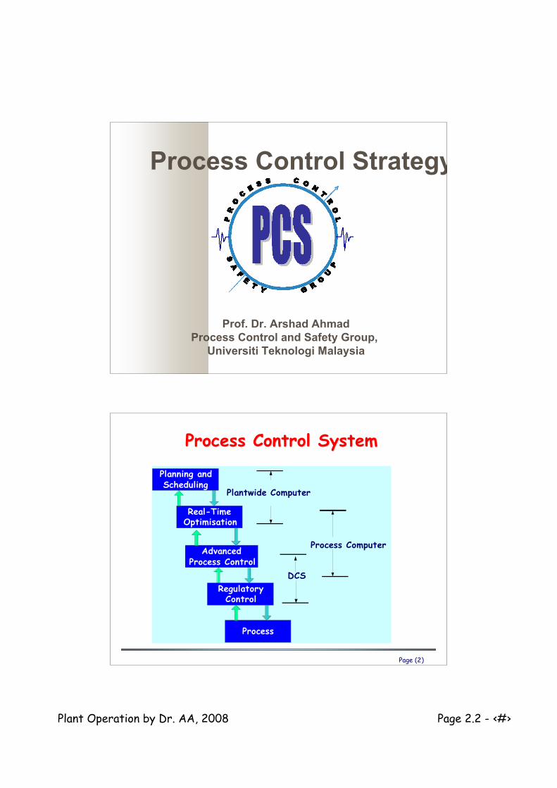
Process Control SystemProcess Control System
Planning andScheduling
RegulatoryControl
AdvancedProcess Control
Real-TimeOptimisation
Process
Process Computer
DCS
Plantwide Computer

Plant Operation by Dr. AA, 2008 Page 2.2 - ‹#›
Regulatory ControlRegulatory Control
Page (4)
Regulatory ControlRegulatory Control
Most of the time, process variables arefixed at some desired set point
The task is therefore to rejectdisturbances, etc
Majority of the controllers are standardthree-term controllers i.e., PID

Plant Operation by Dr. AA, 2008 Page 2.2 - ‹#›
Page (5)
Feedback ControlFeedback Control
Corrective Action Measure, Decide, Correct Robust Process Variables
Controlled Variables Manipulated Variables SISO Configuration
Solution to Most Control Problem
Page (6)
Feedback Control ExampleFeedback Control Example
Controlled variable Temperature
ManipulatedVariable Steam
Flowrate V2 being adjusted
to providecorrective action
TC
v1
v2

Plant Operation by Dr. AA, 2008 Page 2.2 - ‹#›
Page (7)
Feedback Control Block DiagramFeedback Control Block DiagramGd(s)
GP(s)Gv(s)GC(s)
GS(s)
D(s)
CV(s)
CVm(s)
SP(s) E(s) MV(s) ++
+-
Transfer functions
GC(s) = controllerGv(s) = valve +GP(s) = feedback processGS(s) = sensorGd(s) = disturbance process
Variables
CV(s) = controlled variableCVm(s) = measured value of CV(s)D(s) = disturbanceE(s) = errorMV(s) = manipulated variableSP(s) = set point
Page (8)
PID ControllerPID Controller
Developed in the 1940’s, remains workhorse of practice Not “optimal”, based on good properties of each mode Preprogrammed in all digital control equipment ONE controlled variable (CV) and ONE manipulated variable
(MV). Many PID’s used in a plant.
!!"
#$$%
&
'
'++='
++=
(t
eeeKu
SS
KG
D
I
C
D
I
CC
))
))
1
)1
1(
Plant Operation by Dr. AA, 2008 Page 2.2 - ‹#›
Page (9)
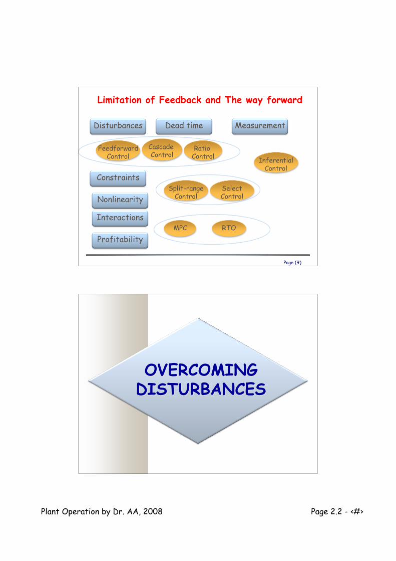
Limitation of Feedback and The way forwardLimitation of Feedback and The way forward
Nonlinearity
Interactions
Constraints
Profitability
Disturbances Dead time Measurement
FeedforwardControl Inferential
Control
Cascade Control
Ratio Control
MPC RTO
Split-rangeControl
SelectControl
OVERCOMINGOVERCOMINGDISTURBANCESDISTURBANCES

Plant Operation by Dr. AA, 2008 Page 2.2 - ‹#›
Page (11)
Improving Disturbance RejectionImproving Disturbance Rejection
Single loop feedback controllers can rejectdisturbances to certain extent.
Cascade control Cascade reduces the effect of specific types
of disturbances. Feedforward control
Feedforward control is a general methodologyfor compensating for measured disturbances
Ratio Control Ratio reduces the effect of feed flow rates
changes
Page (12)
Cascade ControlCascade Control
Benefits Useful in overcoming high frequency noise and
disturbances Also reduces the impact of time delay
Plant Operation by Dr. AA, 2008 Page 2.2 - ‹#›
Page (13)
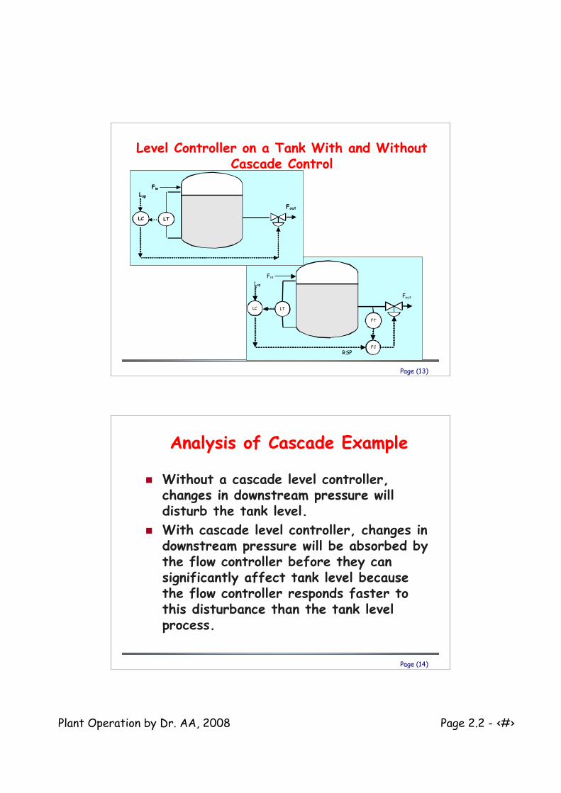
Level Controller on a Tank With and WithoutLevel Controller on a Tank With and WithoutCascade ControlCascade Control
Fin
FC
LT
RSP
FT
Fout
Lsp
LC
Fin
LT
Fout
Lsp
LC
Page (14)
Analysis of Cascade ExampleAnalysis of Cascade Example
Without a cascade level controller,changes in downstream pressure willdisturb the tank level.
With cascade level controller, changes indownstream pressure will be absorbed bythe flow controller before they cansignificantly affect tank level becausethe flow controller responds faster tothis disturbance than the tank levelprocess.
Plant Operation by Dr. AA, 2008 Page 2.2 - ‹#›
Page (15)
With and without cascade controlWith and without cascade control
Page (16)
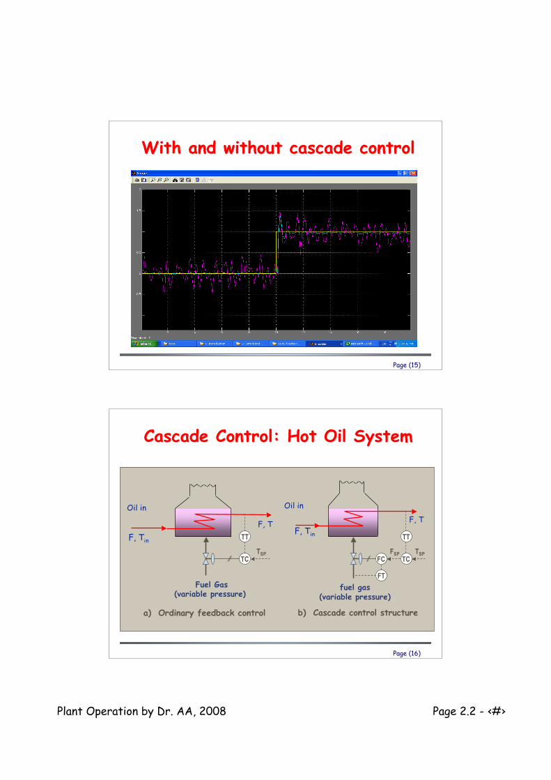
Cascade Control: Hot Oil SystemCascade Control: Hot Oil System
F, T
Oil in
F, Tin
fuel gas(variable pressure)
b) Cascade control structure
FCFSP
TCTSP
FT
TT
F, T
Oil in
Fuel Gas(variable pressure)
a) Ordinary feedback control
TCTSP
F, Tin TT

Plant Operation by Dr. AA, 2008 Page 2.2 - ‹#›
Page (17)
Analysis of Cascade ExampleAnalysis of Cascade Example
Without a cascade level controller,changes in upstream fuel pressureaffects outlet hot oil temperature.
With cascade level controller, changes inupstream pressure will be absorbed bythe flow controller before they cansignificantly affect hot oil temperaturebecause the flow controller respondsfaster to this disturbance than the oiltemperature process.
Page (18)
Cascade Reactor Temperature ControlCascade Reactor Temperature Control
Feed
Product
TT
Cooling
water
TC
Feed
Product
TT
Cooling
water
TCTT
TC
RSP

Plant Operation by Dr. AA, 2008 Page 2.2 - ‹#›
Page (19)
Analysis of ExampleAnalysis of Example
Without cascade, changes in the coolingwater temperature will create a significantupset for the reactor temperature.
With cascade, changes in the cooling watertemperature will be absorbed by the slaveloop before they can significantly affectthe reactor temperature.
Page (20)
Multiple Cascade ExampleMultiple Cascade Example
This approach works because the flow control loop ismuch faster than the temperature control loop whichis much faster than the composition control loop.
FT
AC
AT
TCTT
FC
RSP
RSP

Plant Operation by Dr. AA, 2008 Page 2.2 - ‹#›
Page (21)
Key Features for Cascade Control toKey Features for Cascade Control tobe Successfulbe Successful
Secondary loop should reduce the effectof one or more disturbances.
Secondary loop must be at least 3 timesfaster than master loop.
The secondary loop should be tunedtightly.
Page (22)
Feedforward ControlFeedforward Control
Taking action before disturbancesaffecting the process, thus a PreventiveMechanism

Plant Operation by Dr. AA, 2008 Page 2.2 - ‹#›
Page (23)
Feedforward and Feedback Level ControlFeedforward and Feedback Level Control
Make-upWater
To SteamUsers
LT
LC
Make-upWater
To SteamUsers
LT
FT
FF
To SteamUsers
LT
FT FF
LC +
Make-upWater
Page (24)
Analysis of Feedforward and FeedbackAnalysis of Feedforward and FeedbackLevel ControlLevel Control
Feedback-only must absorb the variations insteam usage by feedback action only.
Feedforward-only handle variation in steamusage but small errors in metering willeventually empty or fill the tank.
Combined feedforward and feedback hasbest features of both controllers.

Plant Operation by Dr. AA, 2008 Page 2.2 - ‹#›
Page (25)
Derivation of FF ControllerDerivation of FF Controller
Cff(s)Y(s)
Gd(s)
D(s)
++Ga(s)
Gff(s)
Gp(s)
Gds(s)
(s)G(s)G(s)G
(s)G(s)G
(s)GforSolving
0(s)GD(s)(s)G(s)G(s)G(s)GD(s)Y(s)
pads
dff
ff
dpaffds
!=
=+=
Page (26)
Feedback ControlFeedback Control
Can effectively eliminate disturbances forfast responding processes.
But it waits until the disturbance upsetsthe process before taking corrective action.
Can become unstable due to nonlinearity anddisturbance upsets.
Plant Operation by Dr. AA, 2008 Page 2.2 - ‹#›
Page (27)
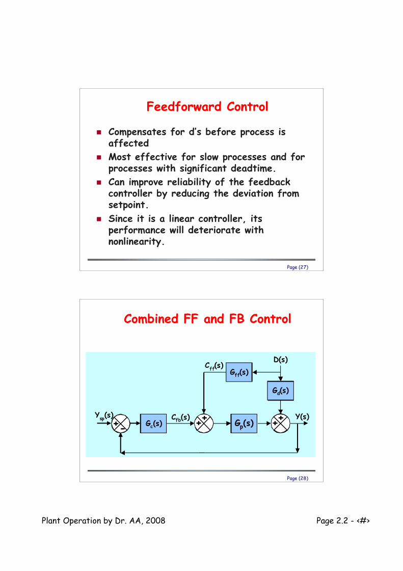
Feedforward ControlFeedforward Control
Compensates for d’s before process isaffected
Most effective for slow processes and forprocesses with significant deadtime.
Can improve reliability of the feedbackcontroller by reducing the deviation fromsetpoint.
Since it is a linear controller, itsperformance will deteriorate withnonlinearity.
Page (28)
Combined FF and FB ControlCombined FF and FB Control
Cfb(s)Y
sp(s)
Gp(s)Y(s)
+++++-Gc(s)
D(s)
Gd(s)
Gff(s)C
ff(s)

Plant Operation by Dr. AA, 2008 Page 2.2 - ‹#›
Page (29)
Example of Combined FF and FBExample of Combined FF and FB
TTPT
PCTC
Condensate
Steam
RSP
Feed
TT
FF
+
Page (30)
Combined FF and FB for theCombined FF and FB for theCSTRCSTR
Steam
Feed
Product
TT
FT
FC
+
TC
TT
FF
RSP

Plant Operation by Dr. AA, 2008 Page 2.2 - ‹#›
Page (31)
Results for CSTRResults for CSTR
-6
-3
0
3
6
-10 10 30 50
Time (seconds)
T'
(K)
FB-only
FF+FBFF-only
Page (32)
Analysis of Results for CSTRAnalysis of Results for CSTR
FB-only returns to setpoint quickly buthas large deviation from setpoint.
FF-only reduces the deviation fromsetpoint but is slow to return tosetpoint.
FF+FB reduces deviation from setpointand provides fast return to setpoint.

Plant Operation by Dr. AA, 2008 Page 2.2 - ‹#›
Page (33)
Ratio ControlRatio Control
Useful when the manipulated variablescales directly with the feed rate to theprocess.
Dynamic compensation is required whenthe controlled variable respondsdynamically different to feed ratechanges than it does to a changes in themanipulated variable.
Page (34)
Ratio Control for WastewaterRatio Control for WastewaterNeutralizationNeutralization
NaOHSolutionAcid
Wastewater
Effluent
FTFT
FC
pHTpHC
! RSP

Plant Operation by Dr. AA, 2008 Page 2.2 - ‹#›
Page (35)
Analysis of Ratio ControlAnalysis of Ratio ControlExampleExample
The flow rate of base scales directly withthe flow rate of the acidic wastewater.
The output of the pH controller is the ratioof NaOH flow rate to acid wastewater flowrate; therefore, the product of thecontroller output and the measured acidwastewater flow rate become the setpointfor the flow controller on the NaOHaddition.
Page (36)
ExampleExample
FT
FT TT
Flue
Gas
Process
FluidFuel
Draw schematic: For a control system that adjusts the ratio offuel flow to the flow rate of the process fluid to control theoutlet temperature of the process fluid. Use a flow controlleron the fuel.

Plant Operation by Dr. AA, 2008 Page 2.2 - ‹#›
Page (37)
Solution: ratioSolution: ratio
FT
FC
FT TT
_ TC
RSPFlue
Gas
Process
FluidFuel
Ratio
Dealing withDealing withConstraintsConstraints

Plant Operation by Dr. AA, 2008 Page 2.2 - ‹#›
Page (39)
Split Range ControlSplit Range Control
Uses more than one manipulated variablesor actuators for one control loop
Page (40)
Split-Range Control: Simple ConceptSplit-Range Control: Simple Concept
F1 F2
PC
setpoint
Desired Pressure Low Medium High
Flow F1 Close Open Open
Flow F2 Open Open Close

Plant Operation by Dr. AA, 2008 Page 2.2 - ‹#›
Page (41)
Split Range Control: Another ExampleSplit Range Control: Another Example
FT
FT
FC
FC
Sometimes a single flow control loop cannot provide accurate flowmetering over the full range of operation.
Split range flow control uses two flow controllers One with a small control valve and one with a large control valve At low flow rates, the large valve is closed and the small valve
provides accurate flow control. At large flow rates, both valve are open.
Larger ValveSmaller Valve
Total Flowrate
Page (42)
Application of Split Range Control:Application of Split Range Control:pH ControlpH Control
Acid
Wastewater
NaOH
Solution
Effluent
FTFT
FC
pHTpHC
RSP!
• Strategy: control of pH using ratio of NaOH to acid waste water• Due to dynamic behaviour, Split range is also required
Split range for this valve

Plant Operation by Dr. AA, 2008 Page 2.2 - ‹#›
Page (43)
Titration Curve for a Strong Acid-StrongTitration Curve for a Strong Acid-StrongBase SystemBase System
0
2
4
6
8
10
12
14
0 0.002 0.004 0.006 0.008 0.01
Base to Acid Ratio
pH
Therefore, for accurate pH control for a widerange of flow rates for acid wastewater, a splitrange flow controller for the NaOH is required.
Page (44)
Application of Split RangeApplication of Split RangeControl: Temperature ControlControl: Temperature Control
TT
CoolingWater
Steam
Split-RangeTemperatureController
TT TC
RSP

Plant Operation by Dr. AA, 2008 Page 2.2 - ‹#›
Page (45)
Split Range Temperature ControlSplit Range Temperature Control
0
20
40
60
80
100
Error from Setpoint for Jacket Temperature
Sig
nal to
Con
trol
Val
ve (
%)
SteamCooling
Water
Page (46)
Override ControlOverride Control
Process are many times operated at thesafety or equipment limits in order tomaximize process throughput.
During upset periods, it is essential thatsafety limits are enforced.

Plant Operation by Dr. AA, 2008 Page 2.2 - ‹#›
Page (47)
Override/Select ControlOverride/Select Control
Override/Select control uses LS and HSaction to change which controller is applied tothe manipulated variable.
Override/Select control uses select action toswitch between manipulated variables usingthe same control objective.
Page (48)
Furnace Tube Temperature Constraint ControlFurnace Tube Temperature Constraint Control
FT
FC
TT TT
LS TCTC
RSP
Flue
Gas
Process
FluidFuel

Plant Operation by Dr. AA, 2008 Page 2.2 - ‹#›
Page (49)
Analysis of Tube Temperature ConstraintAnalysis of Tube Temperature ConstraintControllerController
Under normal operation, the controlleradjusts the furnace firing rate to maintainprocess stream at the setpointtemperature.
At higher feed rates, excessive tubetemperatures can result greatly reducingthe useful life of the furnace tubes.
The LS controller reduces the firing rate toensure that the furnace tubes are notdamaged.
Page (50)
Column Flooding Constraint ControlColumn Flooding Constraint Control
FT
AC
AT
LSDPC
FC
RSP

Plant Operation by Dr. AA, 2008 Page 2.2 - ‹#›
Page (51)
LC
PT
LT PC
Hot Gas
Boiler Drum
Feedwater
Steam
LSS
Loop 2
Loop 1
Discharge Line
Override control to protect boilerOverride control to protect boiler
Page (52)
Hot-Spot Temperature ControlHot-Spot Temperature Control
AutioneeringSystem
TTTT TT TT TT
TC
Example• Temperature controlin catalytic reactor• detect temperaturein various places incatalyst bed.•Action based onhighest temperature
FT