23 accessories - pizzato...23 143 44 44 55 Ø 22,4 54,5 general catalogue hmi 2019-2020 fixing ring...
TRANSCRIPT

23
143
44
55
44
Ø 22,4
54,5
General Catalogue HMI 2019-2020
Fixing ring
Article Description
VE GF121A Technopolymer fixing ring
Accessories
Fixing key
Article Description
VE CH121A1 Technopolymer fixing key for VE GF•••• fixing rings
Mounting adapter
Article Description
E2 1BAC11 3-slot mounting adapter for E2 CP contact blocks and E2 LP LED units
E2 1BAC12 3-slot mounting adapter, oriented, for E2 CP contact blocks and E2 LP LED units
Packs of 20 pcs.
Packs of 10 pcs.
Article Description
VE GF720A Metal fixing ring
Article Description
E2 1BAC21 4-slot mounting adapter for E2 CP contact blocks
E2 1BAC22 4-slot mounting adapter, oriented, for E2 CP contact blocks
Combinable only with selectors E2 •SE•••••••••,keyselectorswitchesE2•SC••••••••,buttonsE2•PU••••••,doublebuttonsE2 •PD•••••••,emergencybuttonsE2•PE••••••,configuredintheappropriateversionsfor4-slotadapter.Combinable with E2 •PQ•••••••quadruplebuttonsandE2•MA••••••joysticks.
Ø 22 … Ø 30 mm adapter
Article Description
VE GF151AAdapterwithringforpanelfixingforØ22devicesonØ30holescompliantwithEN60947-5-1
NotapplicableonE2•PD•••••••-E2•PT•••••••-E2•PQ•••••••double,triple,andquadruplebuttons.Notapplicableinpresenceofshapedrings,labelholders,guardsorprotectioncaps.ItdoesnotaltertheIPprotectiondegreeoftheassociateddevice.
Technical data:Body and ring material: technopolymerProtectiondegree: IP67andIP69K
Tighteningtorque: 2…2.5NmDowelcanberemovedwithasimplescrewdriver
Packs of 10 pcs.
Adapter for DIN rail
Article Description
VE AD3PF9A0
SupportwithØ22holeforfixingonDINrailofthesignallingandcontroldevicesoftheEROUND line
Packs of 10 pcs.
Notsuitableforjoysticksandquadruplebuttons
Not combinable with E2 •PQ•••••••quadruplebuttonsandE2•MA••••••joysticks.

23
144
3014
,8
29,6 2,5
14.9
34.6
29.8 3
General Catalogue HMI 2019-2020
Label holder
Labels with laser engraving
Article Description Pieces/pack.
VE PT32A00A0 Labelholderprovidedwithshapedhole,for18x27mmlabel,withoutlabel 10
VE PT32A10A0Labelholderprovidedwithshapedhole,for18x27mmlabel,andtransparentprotectionlabelwithoutengraving 10
VE PT32A09A••• Labelholderprovidedwithshapedhole,for18x27mmlabel,andglossyaluminium-colouredlabelwithblackengraving 1
Labelholdersforsingledevice,adjustableby90°in90°increments.Theswitchlabelsofothermanufacturerscanbeused(forexample:3MarticleKE-7270-2691-3orGRAFOPLASTarticleSITM612X)aslongastheyhavethefollowingdimensions:base27+0/-0.4mm,height18+0/-0.4mm,thickness0.8±0.4mm.
For ordering engraved labels: Replace the dots •••inthearticlecodeswiththeengravingcodereportedonthetableatpage147.Example:Labelholderprovidedwithlabel,“STOP”engraving.VEPT32A09A••• VEPT32A09AGB0
For ordering engraved labels: Replace the dots ••inthearticlecodeswiththeengravingcodereportedonthetableatpage147.Example:Blacklabelwith"STOP"engraving.VETF12H12•• VETF12H12GB0
Plates
Article Description
VE TR3A770ProtectiveplateforVEPTlabelholderswithoutengraving.Packs of 100 pcs.
Rectangularplate18x27mm,thickness0.4mm,transparentanti-glarepolycarbonate.Idealforprotectingthelabel below
Article Description
VE TR4A970LabelforVEPTlabelholderswithoutengraving,forcutterorlaserengraving.Packs of 100 pcs.
VE TR4A91••• LabelforVEPTlabelholderswithblackindeliblelaserengraving.
Rectangularlabel18x27mm,thickness0,8mm,whitealuminiumRAL9006
For ordering engraved labels: Replace the dots ••• inthearticlecodeswiththeengravingcodereportedonthetableatpage147.Example:Labelwith“STOP”engraving.VE TR4A91••• VE TR4A91GB0
LabelsforsingleEROUNDlinedevices,adjustableby90°in90°increments.Availableinblack,grey,andyellow;theengravingisvialaser,directlyonthelabelitself.Thisavoidshavingtoapplyadditional labels,andthecommanddescriptionremainspermanentandindelible,fortheentirelifetimeofthelabel.Labelsarecustomisablewithvariouslaserengravingtypes,accordingtocustomerrequirements.
It does not alter the IP protection degree of the associated device.
Not applicable on E2 •PD•••••••,E2•PT•••••••,E2•PQ•••••••double,triple,andquadruplebuttons. Notapplicableinpresenceofshapedrings,adaptersfromØ22toØ30mm,guardsorprotectioncaps.
It does not alter the IP protection degree of the associated device.
Not applicable on E2 •PD•••••••,E2•PT•••••••,E2•PQ•••••••double,triple,andquadruplebuttons.
Article Description Pieces/pack.
VE TF32H9700 Greylabel,withoutengraving 10
VE TF12H1700 Blacklabel,withoutengraving 10
VE TF32H5700 Yellowlabel,withoutengraving 10
VE TF32H91•• Greylabel,withindeliblelaserengraving 1
VE TF12H12•• Blacklabel,withindeliblelaserengraving 1
VE TF32H51•• Yellowlabel,withindeliblelaserengraving 1

23
145 General Catalogue HMI 2019-2020
Accessories
Technical data:Body and ring material: technopolymerProtection degree: IP67andIP69KTighteningtorque: 2…2.5Nm
Packs of 10 pcs.
Protection cap
Article Description
VE CA1A1 Protectivecapforsingleflushbutton(panelwidthfrom1to5mm)
VE CA1B1Protectioncapforsingleprojectingbutton(panelwidthfrom1to5mm)
VE CA1C1Protectioncapfordoubleandtripleprojectingbuttons(panelwidthfrom1to6mm)
VE CA1D1Protectioncapfordoubleflushbutton(panelwidthfrom1to6mm)
Notapplicableinpresenceofshapedrings,labelholders,adaptersfromØ22toØ30mmorprotectionguards.
Technical data:Material: silicon suitable for contact with foodProtectiondegree: IP67Ambienttemperature: -40°C…+80°CIdealfordustyfoodenvironmentsorinpresenceofwaterandsand.
Packs of 10 pcs.
Shaped ring
Article Description Pieces/pack.
VE GP12H1A Shapedringforsingledevice 50
VE GP12L1AShapedringforE2•PD•••••••- E2•PT•••••••doubleandtriplebutton 50
VE GP12M1A ShapedringforquadruplebuttonE2•PQ••••••• 10Notapplicableinpresenceoflabelholders,adaptersfromØ22toØ30mm,guardsorprotectioncaps.It does not alter the IP protection degree of the associated device.
Closing cap
Article Description
E2 1TA1A110 Black closing cap for Ø 22 mm holes
Packs of 10 pcs.
Dust protection
Article Description
VE PR3A70 TransparentdustprotectionforE2seriescontactblocks.Suitableforallpanelmountingcontactblocks.
Packs of 50 pcs.
Connection blockConnectionblockswithoutelectricalcontactsanddimensionsidenticaltothoseofthecontactblocks.IfcombinedwiththeVEDLseriesluminousdiscitcanbemountedwithoutusingterminalsorcrimping.
Article Description
VE BC2PV1 Panel mounting connection block
VE BC2FV1 Connection block for base mounting
Packs of 10 pcs.

23
146
ES 31001
ES 31001
E2 1PE••••
VE GP32F5A
VE GP32B5A
E2 1PU2F••••
ES 31001
VE GP32A5A
E2 1PL2S••••
ES 31000
VE GG3EA7A
44
66
38,1
26,4
58,4
2,5
128
40
35 20
43
38 27
38
66
35,2
Ø 4
5
General Catalogue HMI 2019-2020
Windowed protection guard
Article Description
VE GP32A5ACylindrical yellow protection guard with 4 windows
Cylindrical protection guard
Colour Article Description
yellow VE GP32B5ACylindrical yellow protection guard
black VE GP32B1ACylindrical black protection guard
green VE GP32B4ACylindrical green protection guard
blue VE GP32B6ACylindrical blue protection guard
It does not alter the IP protection degree of the associated device.Notapplicableinpresenceofshapedrings,labelholders,adaptersfromØ22toØ30mmorprotectioncaps.
It does not alter the IP protection degree of the associated device.Notapplicablewithattachedlabelholder.
It does not alter the IP protection degree of the associated device.Not applicable on emergency buttons of the E2 •PE•••••• series.Notapplicableinpresenceofshapedrings,labelholders,adaptersfromØ22toØ30mmorprotectioncaps.
Open protection guard
Article Description
VE GP32F5A
Rectangular open yellow protection guard complete with 4 screws (for panelsofthicknessfrom1to3.5mm)
It does not alter the IP protection degree of the associated device.Notapplicableinpresenceofshapedrings,labelholders,adaptersfromØ22toØ30mmorprotection caps.
Application examples of guards
Lockable guard
Article Description
VE GG3EA7A
Lockable guard complete with 4 screws (for panel thicknesses between 1and3.5mm)
Ideal for protecting devices which must not be actuatedinvoluntarily.

23
147
IT0 ARRESTO GB0 STOP FR0 ARRÊT DE0 HALTIT1 AVVIO GB1 START FR1 MARCHE DE1 START
IT2 CHIUSO GB2 CLOSE FR2 FERMÉ DE2 ZU
IT3 SU GB3 UP FR3 MONTÉE DE3 AUF
IT4 GIÚ GB4 DOWN FR4 DESCENTE DE4 AB
IT5 SPENTO GB5 OFF FR5 ARRÊT DE5 AUS
IT6 ACCESO GB6 ON FR6 MARCHE DE6 EINIT7 INSERVIZIO GB7 RUN FR7 ENSERVICE DE7 BETRIEBIT8 ERRORE GB8 FAULT FR8 PANNE DE8 STÖRUNG
IT9 TEST GB9 TEST FR9 ESSAI DE9 PRÜFUNG
IT10 SPENTO ACCESO GB10 OFF ON FR10 ARRÊTMARCHE DE10 AUSEINIT11 MAN.AUTO GB11 MAN.AUTO FR11 MAN.AUTO DE11 HANDAUTOIT12 MAN.0AUTO GB12 MAN.0AUTO FR12 MAN.0AUTO DE12 HAND0AUTOIT13 MARCIA GB13 DRIVE FR13 MARCHE DE13 ANTRIEBIT14 RIAVVIA GB14 RESET FR14 REARM. DE14 ENTSPERREN
IT15 AVANTI GB15 FORWARD FR15 AVANT DE15 VORWÄRTS
IT16 INDIETRO GB16 REVERSE FR16 ARRIÈRE DE16 RÜCKWÄRTSIT17 AUMENTA GB17 RAISE FR17 MONTER DE17 HEBENIT18 DIMINUISCI GB18 LOWER FR18 DESCENDRE DE18 SENKENIT19 SINISTRA GB19 LEFT FR19 GAUCHE DE19 LINKSIT20 DESTRA GB20 RIGHT FR20 DROITE DE20 RECHTSIT21 FRENO GB21 BRAKE FR21 FERMER/OUVRIR DE21 BREMSEN
IT22 ALTO GB22 HIGH FR22 HAUT DE22 HOCHIT23 BASSO GB23 LOW FR23 BAS DE23 NIEDRIGIT24 VELOCE GB24 FAST FR24 RAPIDE DE24 SCHNELLIT25 LENTO GB25 SLOW FR25 LENT DE25 LANGSAM
IT26 PIÚVELOCE GB26 FASTER FR26 PLUSRAPIDE DE26 SCHNELLERIT27 PIÚLENTO GB27 SLOWER FR27 PLUS LENT DE27 LANGSAMER
IT32 APRIRE GB32 OPEN FR32 OUVRIR DE32 ÖFFNEN
IT63 CHIAMATA GB63 CALL FR63 APPEL DE63 ANRUF
IT64 OCCUPATO GB64 OCCUPIED FR64 OCCUPÉ DE64 BESETZT
IT99 ARRESTO D’EMERGENZA
GB99 EMERGENCY STOP FR99 ARRÊT D’URGENCE DE99 NOT-AUS
General Catalogue HMI 2019-2020
ENGRAVINGS table (text)
Accessories
Code Text Code Text Code Text Code Text
Otherengravingsonrequest

23
148
L1 IEC 60417-2
L2 IEC 60417-2
L3 -
L4 -
L7 -
L8 -
L9 -
L10 -
L11 IEC 60417-2
L12 IEC 60417-2
L14 IEC 60417-2
L15 -
L16 IEC 60417-2
L17 ISO 7000
L18 ISO 7000
L19 - 0I
L20 - 0I
L21 - I0II
L22 - I0II
L24 -
L25 -
L27 ISO 7000
L30 -
L31 -
L54 -
L59 -
L60 -
L61 -
L65 -
L66 -
L67 -
L68 -
L69 -
L70 -
L71 -
L72 -
L73 -
L74 -
L76 -
L77 -
L78 -
L83 -
L84 -
L86 -
L91 -
L96 -
L130 - 100%
L140 -
L142 ISO 7000
L143 ISO 7000
L145 -
L146 ISO 7000
L147 ISO 7000
L148 -
L153 -
L157 -
L161 -
L162 -
L165 -
L170 -
L172 -
L188 -
L213
L226 -
L227 EN 1501
L230 -
L236 -
L240 -
L241 -
L242 -
L243 -
L244 -
L245 -
L246
L247 -
L248 -
L249 -
L250 -
L251 -
L252 -
L253 -
L254 -
L260 -
L262 -
L276 - START
STOP
L277 -
L278 -
L279
L280 -
L287
L293 -
L295 -
L304 -
L305 -
L311 -
L312 -
L315 - 24V=
L316 -
L317 -
L319 -
General Catalogue HMI 2019-2020
ENGRAVINGS table (symbols)
Code Standard Symbol Code Standard Symbol Code Standard Symbol
Otherengravingsonrequest
23
149
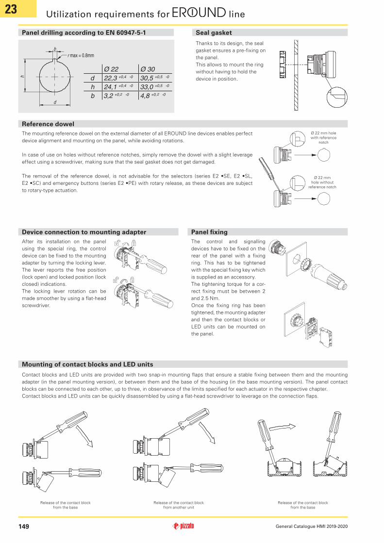
b
h
d
r max = 0.8mm
General Catalogue HMI 2019-2020
Utilization requirements for line
Panel drilling according to EN 60947-5-1
Reference dowel
Seal gasket
ThemountingreferencedowelontheexternaldiameterofallEROUNDlinedevicesenablesperfectdevicealignmentandmountingonthepanel,whileavoidingrotations.
Incaseofuseonholeswithoutreferencenotches,simplyremovethedowelwithaslightleverageeffectusingascrewdriver,makingsurethatthesealgasketdoesnotgetdamaged.
The removal of the reference dowel, is not advisable for the selectors (series E2 •SE, E2 •SL, E2 •SC)andemergencybuttons(seriesE2•PE)withrotaryrelease,asthesedevicesaresubjecttorotary-typeactuation.
Thanks to its design, the seal gasket ensures a pre-fixing on thepanel.This allows to mount the ring withouthavingtoholdthedeviceinposition.
Ø 22 mm hole with reference
notch
Ø 22 mm hole without
reference notch
The control and signalling deviceshavetobefixedontherear of the panel with a fixing ring. This has to be tightenedwith the special fixing key which issuppliedasanaccessory.Thetighteningtorqueforacor-rect fixing must be between 2 and2.5Nm.Once the fixing ring has been tightened, the mounting adapter and then the contact blocks or LED units can be mounted on thepanel.
Mounting of contact blocks and LED units
ContactblocksandLEDunitsareprovidedwithtwosnap-inmountingflapsthatensureastablefixingbetweenthemandthemountingadapter(inthepanelmountingversion),orbetweenthemandthebaseofthehousing(inthebasemountingversion).Thepanelcontactblockscanbeconnectedtoeachother,uptothree,inobservanceofthelimitsspecifiedforeachactuatorintherespectivechapter.ContactblocksandLEDunitscanbequicklydisassembledbyusingaflat-headscrewdrivertoleverageontheconnectionflaps.
Release of the contact block from the base
Release of the contact block from another unit
Release of the contact block from the base
After its installation on the panel using the special ring, the control devicecanbefixedtothemountingadapterbyturningthelockinglever.The lever reports the free position(lockopen)andlockedposition(lockclosed)indications.The locking lever rotation can bemadesmootherbyusingaflat-headscrewdriver.
Device connection to mounting adapter Panel fixing

23
150General Catalogue HMI 2019-2020
Lenses for E2 indicator lights
The E2 indicator lights are provided withinterchangeablelensesindifferentcolours.The lenses canbe removed andmountedby simply turning them clockwise and anticlockwise respectively, without usingtools.For a correct colour rendering, it is necessary to use the correct combination between colour of the indicator light lens andcolouroftheLEDunitappliedtoit.
Lenses for buttons and illuminated buttons
The buttons and the illuminated buttonsfeaturereplaceablelenses.To remove the lenses, leveragethem with a pointed object nearthe reference notch on the external diameterofthelensitself.
Theproductwasdesigned tobe installedonswitchingcabinetsorhousingscontainingelectrical circuits.All electrical componentsanddevicesoftheEROUNDseriesthataretobeinstalledinsideswitchingcabinetsorenclosures(e.g.E2CP,E2CF,E2LP,E2LF),arenotprovidedwithsuitableprotectionsagainst:water,highquantitiesofdust,condensation,humidity,steam,corrosiveagents,explosivegases,flammablegasesorotherpollutingagents.TheprotectiondegreeofswitchingcabinetsorenclosuresshallensurethenecessaryprotectiontotheelectricalcomponentsoftheEROUNDseriesinsidethem,dependingontheapplicationarea.
General requirements
ThecovercapssuppliedforhousingsoftheEROUNDseriesmakeitpossibletoclosethescrewsseats,preventingthustheaccumulationofdirtandtampering.Thesecapsareconnectedtosurfacesofthehousing.Thiscreatesthusamonolithicblockshowingnovisible screws,making it aes-theticallypleasingtoo.
Thecapsengagetothecoverwithasimplepressureuntiltheflexibleflapsnapsin.Fortheirremovalitisnecessarytoinsertthepointofatool(e.g.asmallscrewdriver)inthespecialslotoneachcapandtoleverageonthecouplingflaptoopenit.
Screw caps insertion / removal
- Environmentswheredustanddirtcancoverthedeviceandbysedimentationstopitscorrectworking. - Environmentwheresuddentemperaturechangescausecondensation. - Environmentswherecoatingsoficemayformonthedevice. - Environmentswheretheapplicationcausesknocksorvibrationsthatcoulddamagethedevice. - Inenvironmentscontainingexplosiveorinflammablegasesordusts. - Inenvironmentscontainingstronglyaggressivechemicals,wheretheproductsusedcomingintocontactwiththedevicemayimpairitsphysicalorfunctionalintegrity.
Do not use in following environments:
- Usethedevicesfollowingtheinstructions,complyingwiththeiroperationlimitsandthestandardsinforce. - Thedeviceshavespecificapplicationlimits(min.andmax.ambienttemperature,mechanicalendurance,protectiondegree,etc.)Theselimitsaremetbythedifferentdevicesonlyifconsideredindividuallyandnotifcombinedwitheachother.Forfurtherinformationcontactourtechnicaldepartment.
- Theutilizationimpliesknowledgeofandcompliancewithfollowingstandards:IEC60204-1,IEC60947-5-1,ISO12100. - Pleasecontactourtechnicaldepartmentforinformationandassistance(phone+39.0424.470.930/[email protected])inthefol-lowing cases:- casesnotmentionedinthepresentutilizationrequirements.- Innuclearpowerstations,trains,airplanes,cars,incinerators,medicaldevicesoranyapplicationwherethesafetyoftwoormorepersonsdependonthecorrectoperationofthedevices.
Limits of use
- AlldevicesoftheEROUNDseriesarehandoperated.-Donotapplyexcessiveforcetothedeviceonceithasreachedtheendofitsactuationtravel.- Donotexceedthemaximumactuationtravel.- Beforeinstallation,makesurethedeviceisnotdamagedinanypart.- Donotdisassembleortrytorepairthedevice,incaseofdefectorfaultreplacetheentiredevice.- In case the device is deformedor damaged itmust be entirely replaced.Correct operation cannot be guaranteedwhen the device isdeformedordamaged.- Alwaysattachthefollowinginstructionstothemanualofthemachineinwhichthedeviceisinstalled.- Theseoperatinginstructionsmustbekeptavailableforconsultationatanytimeandforthewholeperiodofuseofthedevice.
Using the devices

23
151 General Catalogue HMI 2019-2020
- Installationmustbecarriedoutbyqualifiedstaffonly. - Observeminimumdistancesbetweendevices(ifprovided). - Observethetighteningtorques. - Keeptheelectricalloadbelowthevaluespecifiedbytheutilizationcategory. - Disconnectthepowerbeforetoworkonthecontacts,alsoduringthewiring. - Donotpaintorvarnishthedevices. - Devicescanonlybeinstalledonperforatedsurfaceswithathicknessofbetween1mmand6mmthatcomplywiththeIEC60947-5-1standard.
- Theprotectiondegreeandthecorrectoperationareonlyguaranteediftheproduct is installedonalevelandsmoothsurfaceandifthediameteroftheholesiscompliantwiththeIEC60947-5-1standard.
- Afterandduringtheinstallationdonotpulltheelectricalcablesconnectedtothecontactblocks.Ifexcessivetensionisappliedtotheelectri-calcables,thecontactblockscoulddetachfromtheactuator.
- Duringthecouplinganduncouplingofthecontactblocksfromthemountingadapterorfromthebase,donotdeformorputexcessivestressonthecouplingflaps.Apossibledeformationoftheflapscouldcausethedetachmentofthecontactblocksfromtheirmountingadapter.
- ThehousingsintheEAandESseriesarefittedwithknock-outholesforthepassageofelectricalcables.Opentheseholesusingasuitabletooltoavoiddamagingthehousing.Refrainfromusinghousingsdamagedorcrackedasaresultoferroneousmanoeuvresperformedwhenopeningtheknock-outholes.Afteropeningthehole,removeanyplasticresiduesandinsertacablegland(orsimilardevice)intotheholewithadegreeofprotectionequalorsuperiortothatofthehousing.
- Afterinstallationandbeforecommissioningofthemachine,verify:-thecorrectoperationofthedevice;-thecorrectandfulllockingoftheE21BAC••mountingadaptertothedevice;-thecorrectcouplingofthecontactblocks.
- Periodicallycheckforcorrectdeviceoperation. - Donotdeformormodifythedeviceforanyreason. - Beforeinstallation,makesurethedeviceisnotdamagedinanypart. - Refrainfromopening,disassemblingorattemptingtorepairthedeviceandreplaceitimmediatelyifitappearstobedamaged. - Shouldtheinstallerbeunabletofullyunderstandtheutilizationrequirements,theproductmustnotbeinstalledandthenecessaryassis-tancemayberequested.
Wiring and installation
Providedthatallpreviousrequirementsforthedevicesarefulfilled,forinstallationswithoperatorprotectionfunctionadditionalrequirementsmustbeobserved. - Theutilizationimpliesknowledgeofandcompliancewithfollowingstandards:IEC60204-1,IEC60947-5-1,ENISO13849-1,EN62061,ENISO12100.
- Inemergencybuttonsthesafetycircuitmustbeconnectedtothe.1-.2NCcontactswiththeactuatorinrestposition.TheauxiliarycontactsNO.3-.4mustbeusedinsignallingcircuitsonly.
- Theprotectionfuse(orequivalentdevice)mustbealwaysconnectedinserieswiththeNC.1-.2contactsofthesafetycircuit. - Periodicallyverifythecorrectworkingofthesafetydevices;theperiodicityofthisverificationissettledbythemachinemanufacturerbasedonthemachinedangerdegreeanditdoesnothavetobelessthanoneayear.
- Afterinstallationandbeforecommissioningofthemachine,verify:-thecorrectoperationofthedevice;-thecorrectandfulllockingoftheE21BAC••mountingadapter;-thecorrectcouplingofthecontactblocks.
- FortheE2•PEBZ••••emergencybuttonswithkeyreleasedonotleavethekeyinserted.Apossiblesuddenactivationoftheemergencybuttonwiththekeyinsertedcouldcauseinjuriestotheoperator.
- Allthesafetydevicesinstalledonthemachine(e.g.emergencybutton,stopbutton,automatic/manualmodeselectoretc.)havealimitedendurance.Althoughstillfunctioning,after20yearsfromthedateofmanufacturethedevicemustbereplacedcompletely.Thedateofmanufactureisplacednexttotheproductcode,onthelabelattachedtothepacking.Incaseofparticularlyadverseweatherconditions,theenduranceofthedevicecanbedrasticallyreducedovertime.Regularlycheckthatthesafetydevicesareworkingproperlyandifrequired,replacethem,evenpriortotheabove-mentionedexpirydate.
- Thedeviceisprovidedwithexternalmarkingonitspackaging.Themarkingincludes:Producertrademark,productcode,batchnumberanddateofmanufacture.Thebatch'sfirstletterreferstothemonthofmanufacture(A=January,B=February,etc.).Thesecondandthirddigitsrefertotheyearofmanufacture(19=2019,20=2020,etc.).
- Ifthedeviceisusedforsafetyapplications,inadequateinstallationortamperingcancausepeopleseriousinjuriesandevendeath. - Thesedevicesmustnotbebypassed,removed,turnedordisabledinanyotherway. - Ifthemachinewherethedeviceisinstalledisusedforapurposeotherthanthatspecifiedbytheproducer,thedevicemaynotprovidetheoperatorwithefficientprotection.
- Thesafetycategoryofthesystemcomprisingthesafetydevicealsodependsonexternaldevicesandtheirconnection.Checkthatthedeviceiscapableofperformingthesafetyfunctionenvisagedbytheriskanalysisofthemachine,asprovidedbyENISO13849-1.
Additional requirements for safety applications
Utilization requirements for line
23
152General Catalogue HMI 2019-2020
Utilization requirements for PA, PX, PC series foot switches
General requirements
- Thedeviceisdesignedtobeinstalledonindustrialmachineries. - Theinstallationmustbeperformedonlybyqualifiedstaffawareoftheregulationsinforceinthecountryofinstallation.
- Thedevicemustbeusedexactlyassuppliedandproperlywired. - Itisnotallowedtodisassembletheproductanduseonlypartsofthesame,thedeviceisdesignedtobeusedinitsassembly.Itisprohibitedtomodifythedevice,evenslightlye.g.:replacepartsofit, drill it, lubricate it, clean it with gasoline or gas oil or any aggres-sivechemicalagents.
- Theprotectiondegreeof thedevice refers to theelectrical con-tactsonly.
- Carefullyevaluateall thepollutingagentspresent in theapplica-tion before installing the device, since the IP protection degreerefersexclusivelytoagentssuchasdustandwateraccordingtoEN60529.Thusthedevicemaynotbesuitableforinstallationinenvironmentswithdustinhighquantity,condensation,humidity,steam, corrosive and chemical agents, flammable or explosivegas,flammableorexplosivedustorotherpollutingagents.
- Somedevicesareprovidedwithahousingwithopeningsforcon-nectingtheelectricalcables.Toguaranteeanadequateprotectiondegreeofthedevice,theopeningthatthewiringpassesthroughmust be protected against the penetration of harmful materials by meansofanappropriateseal.Properwiringthereforerequirestheuseofcableglands,connectorsorotherdeviceswithIPprotectiondegreethatisequaltoorgreaterthanthatofthedevice.
- Store the products in their original packaging, in a dry place with temperaturebetween-40°Cand+70°C
- Failuretocomplywiththeserequirementsorincorrectuseduringoperationcanleadtothedamageofthedeviceandthelossofthefunctionperformedbythedeviceitself.Thiswillresultintermina-tion of the warranty on the item and will release the manufacturer fromanyliability.
Using the devices
- Beforeuse,checkifthenationalrulesprovideforfurtherrequire-mentsinadditiontothosegivenhere.
- Avoidcontactofthedevicewithcorrosivefluids. - Donotstressthedevicewithbendingandtorsion. - Donotapplyexcessiveforcetothedeviceonceithasreachedtheendofitsactuationtravel.
- Donotexceedthemaximumactuationtravel. - If specific operating instructions exist for a device (supplied ordownloadable from www.pizzato.com), they must always beincludedwiththemachinemanualandbeavailablefortheentireservicelifeofthemachine.
- If the pedal has one or more metallic tubes, with a housingequippedwithErounddevicesconnectedtotheirends,theutiliza-tionrequirementsindicatedonpages149to151ofthiscatalogueapply.
Wiring and installation
- Installationmustbecarriedoutbyqualifiedstaffonly. - Useofthedeviceislimitedtofunctionasacontrolswitch. - Theproductcanonlybeusedonflatsurfaces. - Neverusethedeviceassupport forothermachinecomponents(cableducts,tubes,etc.)
- Keeptheelectricalloadbelowthevaluespecifiedbytheutilizationcategory.
- Disconnect the power before to work on the contacts, also during thewiring.
- Donotpaintorvarnishthedevices. - Before installation,makesure thedevice isnotdamaged in anypart.
- Duringwiringcomplywiththefollowingrequirements: - Comply with the minimum and maximum sections of electrical conductorsadmittedbyterminals.
- Tightentheelectricalterminalswiththetorqueindicatedinthiscatalogue.
- Donotintroducepollutingagentsintothedeviceas:talc,lubri-cants for cable sliding, powder separating agents for multipolar cables, small strands of copper and other pollutants that could affecttheproperfunctioningofthedevice.
- Beforeclosing thedevicecover (ifpresent)verify thecorrectpositioningofthegaskets.
- Verifythattheelectricalcables,wire-endsleeves,cablenum-beringsystemsandanyotherpartsdonotobstructthecoverfrom closing correctly or if pressed between them do not damageorcompresstheinternalcontactblock.
- For deviceswith integrated cable, the free end of the cablemust be properly connected inside a protected housing. Theelectrical cable must be properly protected from cuts, impacts, abrasion,etc.
- Check that the device application meets the requirementsdescribedinparagraph"Donotuseinfollowingenvironments"and"Limitsofuse"onpage150.
- Afterinstallationandbeforecommissioningofthemachine,verify: - thecorrectoperationofthedeviceandallitsparts; - thecorrectwiringandtighteningofallscrews.
- Performthefollowingsequenceofchecksbeforethemachineiscommissioned and at least once a year (or after a prolonged shut-down).1.Thepedalmust run freely, and the actuation travelmust belinear.Noobjectsor foreignbodiesmaybepresentbeneaththepedal,whichwouldimpedeitsactuation.
2.Check that the actuating force is compatible with factory defaults.
3.Checkthatthesafetyleverisfunctioningcorrectly:itmustnotbepossibletoactuatethepedal,withoutfirsthavingloweredthesafetylever(wherepresent).
4.Check that the locking mechanism of the pedal actuator (where present)isfunctioningcorrectly.
5.Check that the electrical connecting cable and associated cable glandareingoodcondition,andfirmlyattachedtothedevice.
6.Checkthat,whenthepedalisactuated,themachinebehavesasexpected.
7.Allexternalpartsmustbeundamaged.8.Ifthedeviceisdamaged,replaceitcompletely.
- Should the installer be unable to fully understand the utilization requirements,theproductmustnotbeinstalledandthenecessaryassistancemayberequested.