2.3 mode selection - luminex.be€¦ · 1/12 lumisplit v4 temporary manual document information the...
TRANSCRIPT
1/12
LumiSplit V4 temporary manual
Document information
The following document requires LumiNet Monitor 2.1.6 to be installed on your computer. The application can be downloaded at http://www.luminex.be/support/. This document gives a quick description of the functionalities available in v4 firmware. The document details these functionalities for both LumiSplit 2.10 and 1.6 models. Luminex recommends you to read the quick start guide of each related product before reading this document.
2.3 Mode selection
Mode definition
A/B Splitter (2.10 only)
The LumiSplit will run in A/B splitter mode. This is the default mode
Backup (2.10 only)
Zone A input becomes the main input, Zone B the backup input. In case of DMX loss on Zone A, the splitter will switch automatically to zone B. This mode can be used to create a backup situation for two Ethernet-DMX converters or two network processors. In case of failure of the first device, the LumiSplit will automatically switch to the other device. When DMX signal is lost on input A, A LED turns red, and all output LEDs turn red as well. This better indicates the LumiSplit 2.10 has switched to the secondary input. When DMX signal is back available on input A, the A LED will turn blue again. However, to give control back to the input, you need to press the A input button. All output LEDs will turn Blue/Cyan again.
HTP merging (2.10 only)
The LumiSplit 2.10 will merge the two DMX inputs according the Highest Takes Precedence policy. RDM communication with connected end points is no longer active.

2/12
LumiSplit V4 temporary manual
LTP merging
The LumiSplit will merge the two DMX input according the Latest Takes Precedence policy. RDM communication with connected end points is no longer active.

3/12
LumiSplit V4 temporary manual
Regeneration on zone A (2.10 only)
The LumiSplit 2.10 will re-generate the incoming DMX signal with some new parameters. This parameters can be selected through LumiNet monitor (See page 7). Three different speeds are available (slow, medium, fast). Default speed is medium. The newly created DMX signal will be available from all output linked to input A. RDM communication with connected end points is no longer active on this zone.
Regeneration on zone B (2.10 only)
The LumiSplit 2.10 will re-generate the incoming DMX signal with some new parameters. This parameters can be selected through LumiNet monitor (See page 7). Three different speeds are available (slow, medium, fast). Default speed is medium. The newly created DMX signal will be available from all output linked to input B. RDM communication with connected end points is no longer active on this zone.
Regeneration on all zones
Same as above for both inputs. RDM communication with connected end points is no longer active on both zones.
Dark mode
Dark mode set the brightness to all LEDs to a low value. This avoids the LumiSplit to generate to much light from its LEDs, where darkness is a must have. Once you press one of the button of the front panel, the brightness will go back to full for few seconds.
User preset 1&2 (2.10)
Two user profiles can be stored in outlet 9&10 (LumiSplit 2.10). This allows you to easily recall your favorite configuration, or alternate between two configurations for different applications. To record a profile, and once in the selection mode, simply hold one of the two buttons to store your configuration. Once the output LED start blinking on its own, you can release the button. To recall the profile, once in selection mode, simply press on the output button to reload the profile. These actions can also be performed through LumiNet Monitor (see page 7).

4/12
LumiSplit V4 temporary manual
2.4 Front panel lock The front panel can be locked/unlocked through LumiNet Monitor as well. See how to proceed on page 6. 2.5 Factory reset The LumiSplit can be reset through LumiNet Monitor as well. See how to proceed on page 10 #newRDMexperience Not only the LumiSplit can provide you with some great features directly from its front panel, the unit can also be remotely configured and monitored, all through RDM connectivity. Once LumiNet Monitor is connected to a Luminex Ethernet-DMX converter with RDM enabled, the software will provide you with a comprehensive set of tools to monitor and configure your LumiSplit. The LumiSplit can be monitored and configured through any third party RDM controller. S Luminex recommends you to use a Luminex converter and LumiNet Monitor to enter a new RDM experience. LumiNet Monitor 2.1.5 and LumiSplit firmware v4 are necessary to take full benefit of all the features listed below.
5/12
LumiSplit V4 temporary manual
Discovery
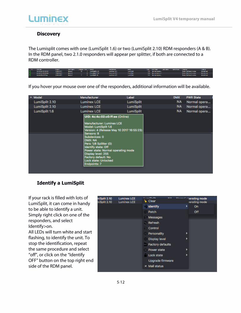
The Lumisplit comes with one (LumiSplit 1.6) or two (LumiSplit 2.10) RDM responders (A & B). In the RDM panel, two 2.1.0 responders will appear per splitter, if both are connected to a RDM controller.
If you hover your mouse over one of the responders, additional information will be available.
Identify a LumiSplit
If your rack is filled with lots of LumiSplit, it can come in handy to be able to identify a unit. Simply right click on one of the responders, and select Identify>on. All LEDs will turn white and start flashing, to identify the unit. To stop the identification, repeat the same procedure and select “off”, or click on the “Identify OFF” button on the top right end side of the RDM panel.

6/12
LumiSplit V4 temporary manual
Lock/Unlock the front panel
To lock the device, simply right click on one of the responders, and select Lock state>Front Panel Locked. To unlock the device, repeat the same operation, and select Lock state>unlocked.
Dark Mode
The LumiSplit offers you to lower down the brightness of the LEDs. Right click on one of the responders, and select display level. Here you can set the brightness either to low or full. There is no intermediate value available for the brightness of the LEDs.
7/12
LumiSplit V4 temporary manual
Mode selection
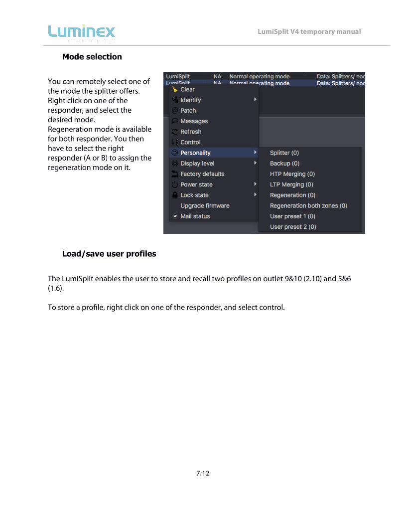
You can remotely select one of the mode the splitter offers. Right click on one of the responder, and select the desired mode. Regeneration mode is available for both responder. You then have to select the right responder (A or B) to assign the regeneration mode on it.
Load/save user profiles
The LumiSplit enables the user to store and recall two profiles on outlet 9&10 (2.10) and 5&6 (1.6). To store a profile, right click on one of the responder, and select control.
8/12
LumiSplit V4 temporary manual
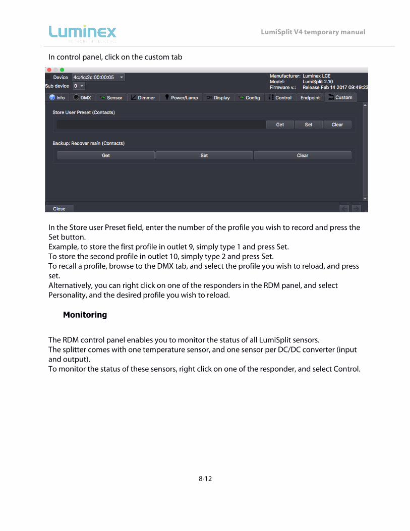
In control panel, click on the custom tab
In the Store user Preset field, enter the number of the profile you wish to record and press the Set button. Example, to store the first profile in outlet 9, simply type 1 and press Set. To store the second profile in outlet 10, simply type 2 and press Set. To recall a profile, browse to the DMX tab, and select the profile you wish to reload, and press set. Alternatively, you can right click on one of the responders in the RDM panel, and select Personality, and the desired profile you wish to reload.
Monitoring
The RDM control panel enables you to monitor the status of all LumiSplit sensors. The splitter comes with one temperature sensor, and one sensor per DC/DC converter (input and output). To monitor the status of these sensors, right click on one of the responder, and select Control.

9/12
LumiSplit V4 temporary manual
Click on the sensor tab. The temperature sensor will indicate the actual inner temperature of the selected LumiSplit. The contact sensors will display the status of all DC/DC converters. A sensor with a value of 1 means the DC/DC converter is perfectly working.

10/12
LumiSplit V4 temporary manual
Factory Reset
The unit can be reset from RDM as well. To proceed, right click on one of the responder, and select Factory Default.
Messages
The Lumisplit is able to send messages over RDM. You can then be notified about any change on the LumiSplit. To display the message window, right click on one of the responders, and select Messages.

11/12
LumiSplit V4 temporary manual
Upgrade the LumiSplit
The LumiSplit splitters are the world first splitters to be upgradable through RDM. To upgrade the unit, you'll need a Luminex Ethernet-DMX converter, and LumiNet Monitor 2.1.5 at least. Please bear in mind only one instance of LumiNet Monitor should run on the network during the firmware upgrade. Download the latest LumiSplit firmware on our web site, and extract the archive. Connect your computer to the node, and enabled RDM on one port. Connect this port to an input of the splitter. In LumiNet Monitor RDM panel, first go to preference menu>RDM>Timing. Here, set the following timing to for a faster upgrade: Outlet interval:100ms Keep alive:2s
In the RDM device panel, select a LumiSplit, and right click on one of the responder, and select Upgrade Firmware.
12/12
LumiSplit V4 temporary manual
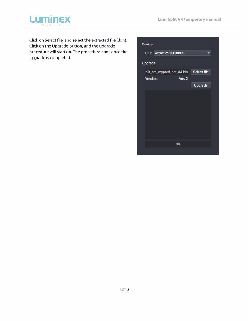
Click on Select file, and select the extracted file (.bin). Click on the Upgrade button, and the upgrade procedure will start on. The procedure ends once the upgrade is completed.