230.1r-90 state-of-the-art report on soil cementcivilwares.free.fr/aci/mcp04/2301r_90.pdf · aci...
TRANSCRIPT
ACI 230.1R-90(Reapproved 1997)
State-of-the-Art Report on Soil Cement
reported by ACI Committee 230
Wayne S. Adaska, Chairman
Ara Arman Richard L. De GraffenreidRobert T. Barclay John R. HessTheresa J. Casias Robert H. KuhlmanDavid A. Crocker Paul E. Mueller
Harry C. RoofDennis W. SuperJames M. WinfordAnwar E. Z. Wissa
Soil cement is a denseiy compacted mixture of portland cement, soil/aggregate, and water. Used primarily as a base material for pave-ments, soil cement is also being used for slope protection, low-permeability liners, foundation stabilization, and other applications.This report contains information on applications, material proper-ties, mix proportioning, construction, and quality-control inspectionand testing procedures for soil cement.This report 's intent is to pro-vide basic information on soil-cement technology with emphasis oncurrent practice regarding design, testing, and construction.
Keywords: aggregates; base courses; central mixing plant; compacting; con-struction; fine aggregates; foundations; linings; mixing; mix proportioning;moisture content; pavements; portland cements; properties; slope protection;soil cement; soils; soil stabilization; soil tests; stabilization; tests; vibration.
CONTENTSChapter 1-Introduction
1.1 -Scope1.2-Definitions
Chapter 2-Applications2.1 -General2.2-Pavements2.3-Slope protection2.4-Liners2.5-Foundation stabilization2.6-Miscellaneous applications
Chapter 3-Materials3.1-Soil3.2-Cement3.3-Admixtures3.4-Water
Chapter 4-Properties4. l-General4.2-Density4.3-Compressive strength
ACI Committee Reports, Guides, Standard Practices, andCommentaries are intended for guidance in designing, plan-ning, executing, or inspecting construction and in preparingspecifications. References to these documents shall not bemade in the Project Documents. If items found in these doc-uments are desired to be a part of the Project Documents, theyshould be phrased in mandatory language and incorporatedinto the Project Documents.
230.1
4.4-Flexural strength4.5-Permeability4.6-Shrinkage4.7-Layer coefficients and structural numbers
Chapter 5-Mix proportioning5.1-General5.2-Proportioning criteria5.3-Special considerations
Chapter 6-Construction6.1-General6.2-Materials handling and mixing6.3-Compaction6.4-Finishing6.5-Joints6.6-Curing and protection
Chapter 7-Quality-control testing andinspection
7.1 -General7.2-Pulverization (mixed in place)7.3-Cement-content control7.4-Moisture content
*7.5 -Mixing uniformity7.6-Compaction7.7-Lift thickness and surface tolerance
Chapter 8-References8.1-Specified references8.2-Cited references
1-INTRODUCTION1.1-Scope
This state-of-the-art report contains information onapplications, materials, properties, mix proportioning,design, construction, and quality-control inspection and
Copyright 0 1990, American Concrete Institute.All rights reserved, including rights of reproduction and use in any form or
by any means, including the making of copies by any photo process, or by anyelectronic or mechanical device, printed, written, or oral, or recording for soundor visual reproduction for use in any knowledge or retrieval system or device,unless permission in writng is obtained from the copyright proprietors.
R-l

230.1 R-2 ACI COMMITTEE REPORT
testing procedures for soil cement. The intent of thisreport is to provide basic information on soil-cementtechnology with emphasis on current practice regardingmix proportioning, properties, testing, and construc-tion.
This report does not provide information on fluid orplastic soil cement, which has a mortarlike consistencyat time of mixing and placing. Information on this typeof material is provided by ACI Committee 229 onControlled Low-Strength Material (CLSM). Roller-compacted concrete (RCC), which is a type of no-slumpconcrete compacted by vibratory roller, is not coveredin this report. ACI Committee 207 on Mass Concretehas a report available on roller-compacted concrete.
1.2-DefinitionsSoil cement-AC1 116R defines soil cement as “a
mixture of soil and measured amounts of portland ce-ment and water compacted to a high density.” Soil ce-ment can be further defined as a material produced byblending, compacting, and curing a mixture of soil/ag-gregate, portland cement, possibly admixtures includ-ing pozzolans, and water to form a hardened materialwith specific engineering properties. The soil/aggregateparticles are bonded by cement paste, but unlike con-crete, the individual particle is not completely coatedwith cement paste.
Cement content-Cement content is normally ex-pressed in percentage on a weight or volume basis. Thecement content by weight is based on the oven-dryweight of soil according to the formula
Cw = weight of cementOven-dry weight of soil
x 100
The required cement content by weight can be con-verted to the equivalent cement content by bulk vol-ume, based on a 94-lb U.S. bag of cement, which has aloose volume of approximately 1 ft3, using the follow-ing formula’
c
Y
= D - [I+&001 x 100 100
94
where
Cv = cement content, percent by bulk volume ofcompacted soil cement
D = oven-dry density of soil-cement in lb/ft3Cw = cement content, percent by weight of
oven-dry soil
The criteria used to determine adequate cement fac-tors for soil-cement construction were developed as apercentage of cement by volume in terms of a 94-lbU.S. bag of cement. The cement content by volume interms of other bag weights, such as an 80-lb Canadianbag, can be determined by substituting 80 for 94 in thedenominator of the preceding formula.
2-APPLICATIONS2.1 -General
The primary use of soil cement is as a base materialunderlaying bituminous and concrete pavements. Otheruses include slope protection for dams and embank-ments; liners for channels, reservoirs, and lagoons; andmass soil-cement placements for dikes and foundationstabilization.
2.2-PavementsSince 1915, when a street in Sarasota, Fla. was con-
structed using a mixture of shells, sand, and portlandcement mixed with a plow and compacted, soil cementhas become one of the most widely used forms of soilstabilization for highways. More than 100,000 miles ofequivalent 24 ft wide pavement using soil cement havebeen constructed to date. Soil cement is used mainly asa base for road, street, and airport paving. When usedwith a flexible pavement, a hot-mix bituminous wear-ing surface is normally placed on the soil-cement base.Under concrete pavements, soil cement is used as a baseto prevent pumping of fine-grained subgrade soils un-der wet conditions and heavy truck traffic. Further-more, a soil-cement base provides a uniform, strongsupport for the pavement, which will not consolidateunder traffic and will provide increased load transfer atpavement joints. It also serves as a firm, stable work-ing platform for construction equipment during con-crete placement.
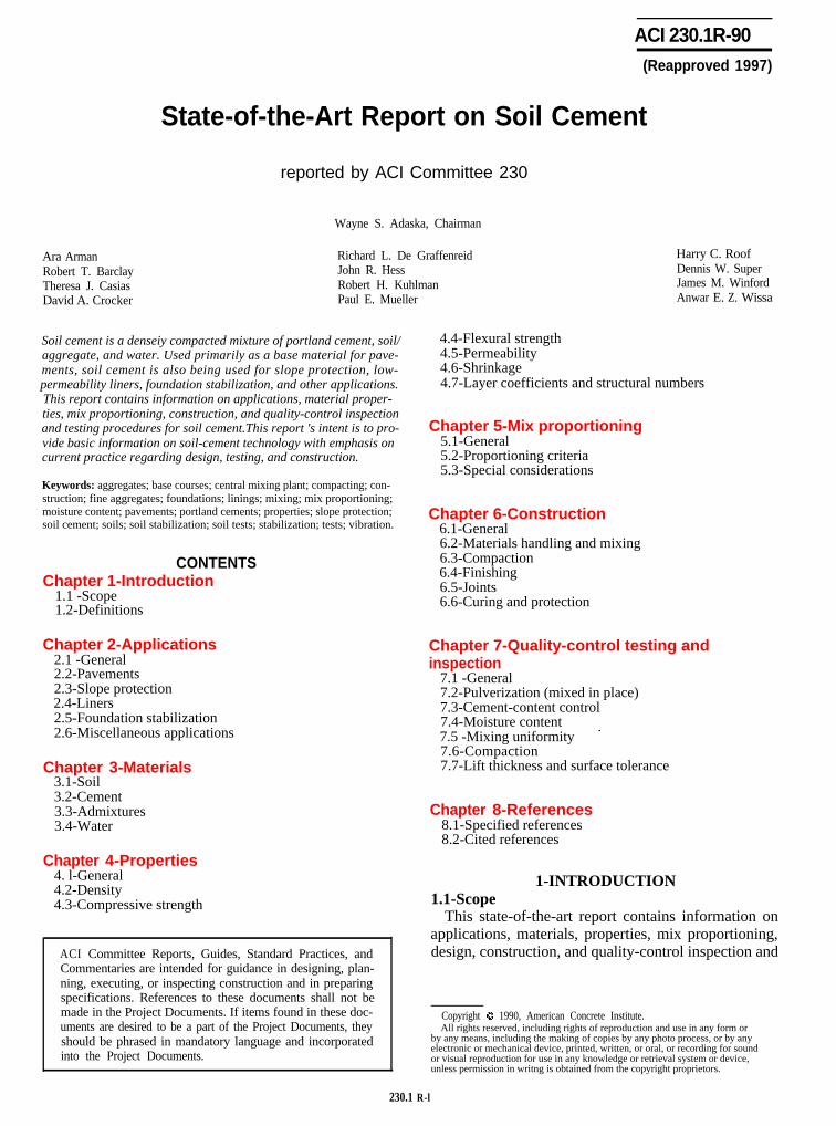
Failed flexible pavements have been recycled with ce-ment, resulting in a new soil-cement base (Fig. 2.1).
Recycling increases the strength of the base without re-moving the old existing base and subbase materials andreplacing them with large quantities of expensive newbase materials. In addition, existing grade lines anddrainage can be maintained. If an old bituminous sur-face can be readily pulverized, it can be considered sat-isfactory for inclusion in the soil-cement mixture. If, onthe other hand, the bituminous surface retains most ofits original flexibility, it is normally removed ratherthan incorporated into the mixture.The thickness of a soil-cement base depends on var-ious factors, including: (1) subgrade strength, (2) pave-ment design period, (3) traffic and loading conditions,including volume and distribution of axle weights, and(4) thicknesss of concrete or bituminous wearing sur-face. The Portland Cement Association (PCA),2,3 theAmerican Association of State Highway and Transpor-tation Officials (AASHTO),4 and the U.S. Army Corpsof Engineers (USACE), 5,6 have established methods fordetermining design thickness for soil-cement bases.Most in-service soil-cement bases are 6 in. thick. Thisthickness has proved satisfactory for service conditionsassociated with secondary roads, residential streets, andlight-traffic air fields. A few 4 and 5 in. thick baseshave given good service under favorable conditions oflight traffic and strong subgrade support. Many milesof 7 and 8 in. thick soil-cement bases are providinggood performance in primary and high-traffic second-ary pavements. Although soil-cement bases more than
SOIL CEMENT 230.1R-3
Fig.2.1-Old bituminous mat being scarified and pulverized for incorporation insoil-cement mix
9 in. thick are not common, a few airports and heavyindustrial pavement project3 have been built with mul-tilayered thicknesses up to 32 in.
Since 1975, soil-cement base courses incorporatinglocal soils with portland cement and fly ash have beenconstructed in 17 states.7 Specification guidelines and acontractor’s guide for constructing such base coursesare available from the Electric Power Research Insti-tute.8
2.3-Slope protectionFollowing World War II, there was a rapid expan-
sion of water resource projects in the Great Plains andSouth Central regions of the U.S. Rock riprap of sat-isfactory quality for upstream slope protection was notlocally available for many of these projects. High costsfor transporting riprap from distant quarries to thesesites threatened the economic feasibility of some proj-ects. The U.S. Bureau of Reclamation (USBR) initiateda major research effort to study the suitability of soilcement as an alternative to conventional riprap. Basedon laboratory studies that indicated soil cement madewith sandy soils could produce a durable erosion-resis-tant facing, the USBR constructed a full-scale test sec-tion in 1951. A test-section location along the southeastshore of Bonny Reservoir in eastern Colorado was se-lected because of severe natural service conditions cre-ated by waves, ice, and more than 100 freeze-thawcycles per year. After 10 years of observing the test sec-tion, the USBR was convinced of its suitability andspecified soil cement in 1961 as an alternative to riprapfor slope protection on Merritt Dam, Nebraska, and
later at Cheney Dam, Kansas. Soil cement was bid atless than 50 percent of the cost of riprap and produceda total savings of more than $1 million for the twoprojects.
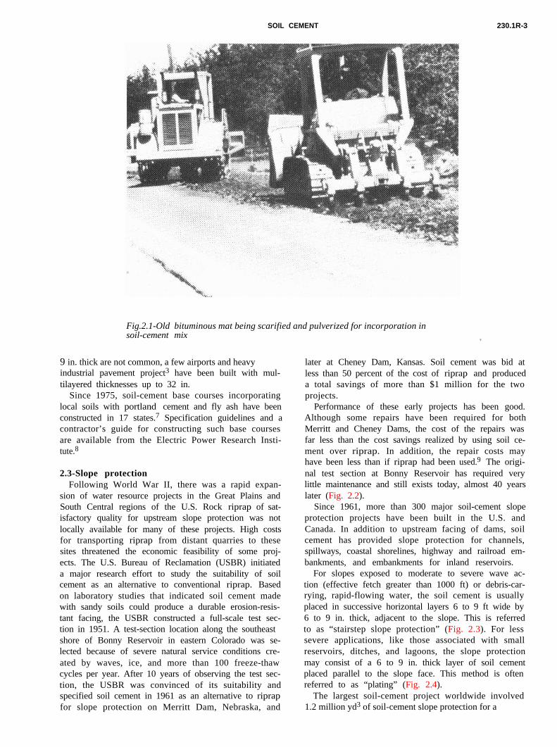
Performance of these early projects has been good.Although some repairs have been required for bothMerritt and Cheney Dams, the cost of the repairs wasfar less than the cost savings realized by using soil ce-ment over riprap. In addition, the repair costs mayhave been less than if riprap had been used.9 The origi-nal test section at Bonny Reservoir has required verylittle maintenance and still exists today, almost 40 yearslater (Fig. 2.2).
Since 1961, more than 300 major soil-cement slopeprotection projects have been built in the U.S. andCanada. In addition to upstream facing of dams, soilcement has provided slope protection for channels,spillways, coastal shorelines, highway and railroad em-bankments, and embankments for inland reservoirs.
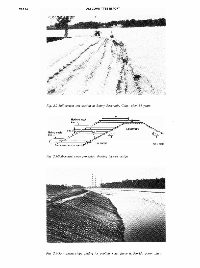
For slopes exposed to moderate to severe wave ac-tion (effective fetch greater than 1000 ft) or debris-car-rying, rapid-flowing water, the soil cement is usuallyplaced in successive horizontal layers 6 to 9 ft wide by6 to 9 in. thick, adjacent to the slope. This is referredto as “stairstep slope protection” (Fig. 2.3). For less
severe applications, like those associated with smallreservoirs, ditches, and lagoons, the slope protectionmay consist of a 6 to 9 in. thick layer of soil cementplaced parallel to the slope face. This method is oftenreferred to as “plating” (Fig. 2.4).The largest soil-cement project worldwide involved1.2 million yd3 of soil-cement slope protection for a
230.1 R-4
Fig. 2.2-Soil-cement test section at Bonny Reservoir, Colo., after 34 years
Minilevel
3
Not to scale
Fig. 2.3-Soil-cement slope protection showing layered design
Fig. 2.4-Soil-cement slope plating for cooling water flume at Florida power plant

SOIL CEMENT 230.1R-5
7000-acre cooling-water reservoir at the South TexasNuclear Power Plant near Houston. Completed in1979, the 39 to 52 ft high embankment was designed tocontain a 15 ft high wave action that would be createdby hurricane winds of up to 155 mph. In addition to the13 miles of exterior embankment, nearly 7 miles of in-terior dikes, averaging 27 ft in height, guide the recir-culating cooling water in the reservoir. To appreciatethe size of this project, if each 6.75 ft wide by 9 in.thick lift were placed end-to-end rather than in stair-step fashion up the embankment, the total distancecovered would be over 1200 miles.
Soil cement has been successfully used as slope pro-tection for channels and streambanks exposed to lat-eral flows. In Tucson, Arizona, for example, occa-sional flooding can cause erosion along the normallydry river beds. From 1983 to 1988, over 50 soil-cementslope protection projects were constructed in this area.A typical section consists of 7 to 9 ft wide horizontallayers placed in stairstep fashion along 2:l (horizontalto vertical) embankment slopes. To prevent scouringand subsequent undermining of the soil cement, thefirst layer or two is often placed up to 8 ft below theexisting dry river bottom, and the ends extend approx-imately 50 ft into the embankment. The exposed slopefacing is generally trimmed smooth during constructionfor appearance. To withstand the abrasive force ofstormwater flows of 25,000 to 45,000 ft3/sec at veloci-ties up to 20 ft/sec, the soil cement is designed for aminimum 7-day compressive strength of 750 psi. In ad-dition, the cement content is increased by two percent-age points to allow for field variations.10
More detailed design information on soil-cementslope protection can be found in References 11 through13.
2.4-LinersSoil cement has served as a low-permeability lining
material for over 30 years. During the mid-1950s, anumber of 1 to 2 acre farm reservoirs in southern Cal-ifornia were lined with 4 to 6 in. thick soil cement. Oneof the largest soil-cement-lined projects is Lake Ca-huilla, a terminal-regulating reservoir for the CoachellaValley County Water District irrigation system insouthern California. Completed in 1969, the 135 acrereservoir bottom has a 6 in. thick soil-cement lining,and the sand embankments forming the reservoir arefaced with 2 ft of soil cement normal to the slope.
In addition to water-storage reservoirs, soil cementhas been used to line wastewater-treatment lagoons,sludge-drying beds, ash-settling ponds, and solid wastelandfills. The U.S. Environmental Protection Agency(EPA) sponsored laboratory tests to evaluate the com-patibility of a number of lining materials exposed tovarious wastes.14 The tests indicated that after 1 year ofexposure to leachate from municipal solid wastes, thesoil cement hardened considerably and cored like port-land cement concrete. In addition, it became lesspermeable during the exposure period. The soil cementwas also exposed to various hazardous wastes, includ-
ing toxic pesticide formulations, oil refinery sludges,toxic pharmaceutical wastes, and rubber and plasticwastes. Results showed that for these hazardous wastes,no seepage had occurred through soil cement following21/2 years of exposure. After 625 days of exposure tothese wastes, the compressive strength of the soil ce-ment exceeded the compressive strength of similar soilcement that had not been exposed to the wastes. Soilcement was not exposed to acid wastes. It was rated“fair” in containing caustic petroleum sludges, indi-cating that the specific combination of soil cement andcertain waste materials should be tested and evaluatedfor compatibility prior to final design decision.
Mix proportions for liner applications have beentested in which fly ash replaces soil in the soil-cementmixture. The fly ash-cement mixture contains 3 to 6percent portland cement and 2 to 3 percent lime.Permeabilities significantly less than 1 X 10⁻⁷ cm/sechave been measured for such fly ash-lime-cement mix-tures, along with unconfined compressive strengths be-fore and after vacuum saturation, which indicate goodfreeze-thaw durability. Is A similar evaluation has beenmade for liners incorporating fly ash, cement, and ben-tonite.16
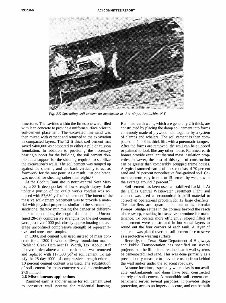
For hazardous wastes and other impoundmentswhere maximum seepage protection is required, a com-posite liner consisting of soil cement and a syntheticmembrane can be used. To demonstrate the construc-tion feasibility of the composite liner, a test section wasbuilt in 1983 near Apalachin, N.Y. (Fig. 2.5). The sec-
tion consisted of a 30 and 40 mil high-density polyeth-ylene (HDPE) membrane placed between two 6-in. lay-ers of soil cement. After compacting the soil-cementcover layer, the membrane was inspected for signs ofdamage. The membrane proved to be puncture-resis-tant to the placement and compaction of soil cementeven with G-in. aggregate scattered beneath the mem-brane.172.5-Foundation stabilizationSoil cement has been used as a massive fill to provide
foundation strength and uniform support under largestructures. In Koeberg, South Africa, for example, soilcement was used to replace an approximately 18 ft thicklayer of medium-dense, liquifiable saturated sand un-der two 900-MW nuclear power plants. An extensivelaboratory testing program was conducted to determinestatic and dynamic design characteristics, liquefactionpotential, and durability of the soil cement. Resultsshowed that with only 5 percent cement content by dryweight, cohesion increased significantly, and it waspossible to obtain a material with enough strength toprevent liquefaction.18
Soil cement was used in lieu of a pile or caissonfoundation for a 38-story office building completed in1980 in Tampa, Fla. A soft limestone layer containingseveral cavities immediately below the building madethe installation of piles or caissons difficult and costly.The alternative to driven foundation supports was toexcavate the soil beneath the building to the top of
230.1R-6 ACI COMMITTEE REPORT
Fig. 2.5-Spreading soil cement on membrane at 3:1 slope, Apalachin, N.Y.
limestone. The cavities within the limestone were filledwith lean concrete to provide a uniform surface prior tosoil-cement placement. The excavated fine sand wasthen mixed with cement and returned to the excavationin compacted layers. The 12 ft thick soil cement matsaved $400,000 as compared to either a pile or caissonfoundation. In addition to providing the necessarybearing support for the building, the soil cement dou-bled as a support for the sheeting required to stabilizethe excavation’s walls. The soil cement was ramped upagainst the sheeting and cut back vertically to act asformwork for the mat pour. As a result, just one bracewas needed for sheeting rather than eight.19
At the Cochiti Dam site in north-central New Mex-ico, a 35 ft deep pocket of low-strength clayey shaleunder a portion of the outlet works conduit was re-placed with 57,650 yd3 of soil cement. The intent of themassive soil-cement placement was to provide a mate-rial with physical properties similar to the surroundingsandstone, thereby minimizing the danger of differen-tial settlement along the length of the conduit. Uncon-fined 28-day compressive strengths for the soil cementwere just over 1000 psi, closely approximating the av-erage unconfined compressive strength of representa-tive sandstone core samples.
In 1984, soil cement was used instead of mass con-crete for a 1200 ft wide spillway foundation mat atRichland Creek Dam near Ft. Worth, Tex. About 10 ftof overburden above a solid rock strata was removedand replaced with 117,500 yd3 of soil cement. To sat-isfy the 28-day 1000 psi compressive strength criteria,10 percent cement content was used. The substitutionof soil cement for mass concrete saved approximately$7.9 million.2.6-Miscellaneous applications
Rammed earth is another name for soil cement usedto construct wall systems for residential housing.
Rammed-earth walls, which are generally 2 ft thick, areconstructed by placing the damp soil cement into formscommonly made of plywood held together by a systemof clamps and whalers. The soil cement is then com-pacted in 4 to 6 in. thick lifts with a pneumatic tamper.After the forms are removed, the wall can be stuccoedor painted to look like any other house. Rammed-earthhomes provide excellent thermal mass insulation prop-erties; however, the cost of this type of constructioncan be greater than comparably equipped frame houses.A typical rammed-earth soil mix consists of 70 percentsand and 30 percent noncohesive fine-grained soil. Ce-ment contents vary from 4 to 15 percent by weight withthe average around 7 percent.20
Soil cement has been used as stabilized backfill. Atthe Dallas Central Wastewater Treatment Plant, soilcement was used as economical backfill material tocorrect an operational problem for 12 large clarifiers.The clarifiers are square tanks but utilize circularsweeps. Sludge settles in the corners beyond the reachof the sweep, resulting in excessive downtime for main-tenance. To operate more efficiently, sloped fillets ofsoil cement were constructed in horizontal layers toround out the four corners of each tank. A layer ofshotcrete was placed over the soil-cement face to serveas a protective wearing surface.
Recently, the Texas State Department of Highwaysand Public Transportation has specified on severalprojects that the fill behind retained earth-wall systemsbe cement-stabilized sand. This was done primarily as aprecautionary measure to prevent erosion from behindthe wall and/or under the adjacent roadway.
At some locations, especially where clay is not avail-able, embankments and dams have been constructedentirely of soil cement. A monolithic soil-cement em-bankment serves several purposes. It provides slopeprotection, acts as an impervious core, and can be built

SOIL CEMENT 230.1 R-7
on relatively steep slopes due to its inherent shearstrength properties. A monolithic soil-cement embank-ment was used to form the 1 l00-acre cooling water res-ervoir for Barney M. Davis Power Plant near CorpusChristi, Tex. The reservoir consisted of 6.5 miles ofcircumferential embankment and 2.1 miles of interiorbaffle dikes. The only locally available material forconstruction was a uniformly graded beach sand. Themonolithic soil-cement design provided both slope pro-tection and served as the impervious core. By utilizingthe increased shear strength properties of the com-pacted cement-stabilized beach sand, the 8 to 22 ft highembankment was constructed at a relatively steep slopeof 1.5H:1V.
Coal-handling and storage facilities have used soilcement in a variety of applications. The Sarpy Creekcoal mine, near Hardin, Mont., utilized soil cement inthe construction of a coal storage slot. Slot storagebasically consists of a long V-shaped trough with a re-claim conveyor at the bottom of the trough. The troughsidewalls must be at a steep and smooth enough slopeto allow the stored coal to remain in a constant state ofgravity flow. The Sarpy Creek storage trough is 750 ftlong and 20 ft deep. The 15,500 yd3 of soil cement wereconstructed in horizontal layers 22 ft wide at the bot-tom to 7 ft wide at the top. During construction, theouter soil-cement edges were trimmed to a finished sideslope of 50 deg. A shotcrete liner was placed over thesoil cement to provide a smooth, highly wear-resistantsurface.
Monolithic soil cement and soil-cement-faced bermshave been used to retain coal in stacker-reclaimer op-erations. The berm at the Council Bluffs Power Stationin southwestern Iowa is 840 ft long by 36 ft high andhas steep 55 deg side slopes. It was constructed entirelyof soil cement with the interior zone of the berm con-taining 3 percent cement. To minimize erosion to theexposed soil cement, the 3.3 ft thick exterior zone wasstabilized with 6 percent cement.
At the Louisa Power Plant near Muscatine, Iowa,only the exterior face of the coal-retaining berm wasstabilized with soil cement. The 4 ft thick soil cementand interior uncemented sand fill were constructed to-gether in 9 in. thick horizontal lifts. A modified as-phalt paving machine was used to place the soil ce-ment. A smooth exposed surface was obtained by trail-ing plates at a 55-deg angle against the edge duringindividual lift construction.
Several coal-pile storage yards have been constructedof soil cement. Ninety-five acres of coal storage yardwere stabilized with 12 in. of soil cement at the Inde-pendence Steam Electric Station near Newark, Ark., in1983. The soil consisted of a processed, crushed lime-stone aggregate. The 12 in. thick layer was placed intwo 6 in. compacted lifts. By stabilizing the area withsoil cement, the owner was able to eliminate the bed-ding layer of coal, resulting in an estimated savings of$3 million. Other advantages cited by the utility includealmost 100 percent coal recovery, a defined perimeterfor its coal pile, reduced fire hazard, and all-weather
access to the area for service and operating equipment.
3-MATERIALS3.1-Soil
Almost all types of soils can be used for soil cement.Some exceptions include organic soils, highly plasticclays, and poorly reacting sandy soils. Tests includingASTM D 4318 are available to identify these problemmaterials.21,22 Section 5.3 of this report, which focuses
on special design considerations, discusses the subjectof poorly reacting sandy soils in more detail. Granularsoils are preferred. They pulverize and mix more easilythan fine-grained soils and result in more economicalsoil cement because they require the least amount ofcement. Typically, soils containing between 5 and 35percent fines passing a No. 200 sieve produce the mosteconomical soil cement. However, some soils havinghigher fines content (material passing No. 200 sieve)and low-plasticity have been successfully and economi-cally stabilized. Soils containing more than 2 percentorganic material are usually considered unacceptablefor stabilization. Types of soil typically used includesilty sand, processed crushed or uncrushed sand andgravel, and crushed stone.Aggregate gradation requirements are not as restric-tive as conventional concrete. Normally the maximumnominal size aggregate is limited to 2 in. with at least55 percent passing the No. 4 sieve. For unsurfaced soilcement exposed to moderate erosive forces, such asslope-protection applications, studies by Nussbaum23
have shown improved performance where the soil con-tains at least 20 percent coarse aggregate (granular ma-terial retained on a No. 4 sieve).
Fine-grained soils generally require more cement forsatisfactory hardening and, in the case of clays, areusually more difficult to pulverize for proper mixing. Inaddition, clay balls (nodules of clay and silt intermixedwith granular soil) do not break down during normalmixing. Clay balls have a tendency to form when theplasticity index is greater than 8. For pavements andother applications not directly exposed to the environ-ment, the presence of occasional clay balls may not bedetrimental to performance. For slope protection orother applications where soil cement is exposed toweathering, the clay balls tend to wash out of the soil-cement structure, resulting in a “swiss cheese” appear-ance, which can weaken the soil-cement structure. TheU.S. Bureau of Reclamation requires that clay ballsgreater than 1 in. be removed, and imposes a 10 per-cent limit on clay balls passing the l-in. sieve.11 Thepresence of fines is not always detrimental, however.Some nonplastic fines in the soil can be beneficial. Inuniformly graded sands or gravels, nonplastic fines in-cluding fly ash, cement-kiln dust, and aggregatescreenings serve to fill the voids in the soil structure andhelp reduce the cement content.
3.2-CementFor most applications, Type I or Type II portland
cement conforming to ASTM C 150 is normally used.
230.1R-8 ACI COMMITTEE REPORT
Table 3.1 - Typical cement requirements for various soil types*’Typical cement
Typical range content for Typical cement contentsof cement moisture-density for durability tests
AASHTO soil ASTM soil requirement,* test (ASTM D 558), (ASTM D 559 and D 506),classification classification percent by weight percent by weight percent by weight
A-l-a GW, GP, GM, 3-5 5 3-5-7SW, SP, SM
A-l-b GM, GP, SM, SP 5-8 6 4-6-8
A-2 GM, GC, SM, SC 5-9 7 5-7-9
A-3 SP 7-l 1 9 7-9-l 1
A-4 CL, ML 7-12 10 8-10-12
A-5 ML, MH, CH 8-13 10 8-10-12
A-6 CL, CH 9-15 12 10-12-14
A-7 MH, CH 10-16 1 3 11-13-15
*Does not include organic or poorly reacting, soils. Also, additional cement may be required for severe exposureconditions such as slope-protect&.
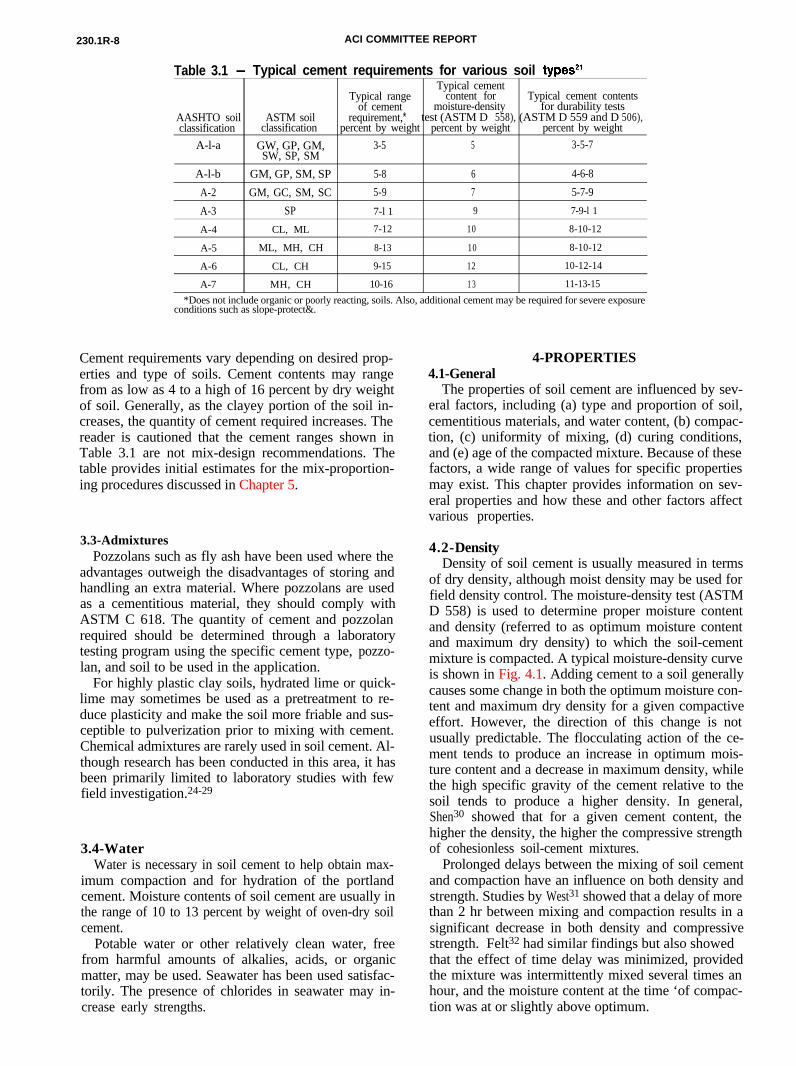
Cement requirements vary depending on desired prop-erties and type of soils. Cement contents may rangefrom as low as 4 to a high of 16 percent by dry weightof soil. Generally, as the clayey portion of the soil in-creases, the quantity of cement required increases. Thereader is cautioned that the cement ranges shown inTable 3.1 are not mix-design recommendations. Thetable provides initial estimates for the mix-proportion-ing procedures discussed in Chapter 5.
3.3-AdmixturesPozzolans such as fly ash have been used where the
advantages outweigh the disadvantages of storing andhandling an extra material. Where pozzolans are usedas a cementitious material, they should comply withASTM C 618. The quantity of cement and pozzolanrequired should be determined through a laboratorytesting program using the specific cement type, pozzo-lan, and soil to be used in the application.
For highly plastic clay soils, hydrated lime or quick-lime may sometimes be used as a pretreatment to re-duce plasticity and make the soil more friable and sus-ceptible to pulverization prior to mixing with cement.Chemical admixtures are rarely used in soil cement. Al-though research has been conducted in this area, it hasbeen primarily limited to laboratory studies with fewfield investigation.24-29
3.4-WaterWater is necessary in soil cement to help obtain max-
imum compaction and for hydration of the portlandcement. Moisture contents of soil cement are usually inthe range of 10 to 13 percent by weight of oven-dry soilcement.
Potable water or other relatively clean water, freefrom harmful amounts of alkalies, acids, or organicmatter, may be used. Seawater has been used satisfac-torily. The presence of chlorides in seawater may in-crease early strengths.
4-PROPERTIES4.1-General
The properties of soil cement are influenced by sev-eral factors, including (a) type and proportion of soil,cementitious materials, and water content, (b) compac-tion, (c) uniformity of mixing, (d) curing conditions,and (e) age of the compacted mixture. Because of thesefactors, a wide range of values for specific propertiesmay exist. This chapter provides information on sev-eral properties and how these and other factors affectvarious properties.
4.2-DensityDensity of soil cement is usually measured in terms
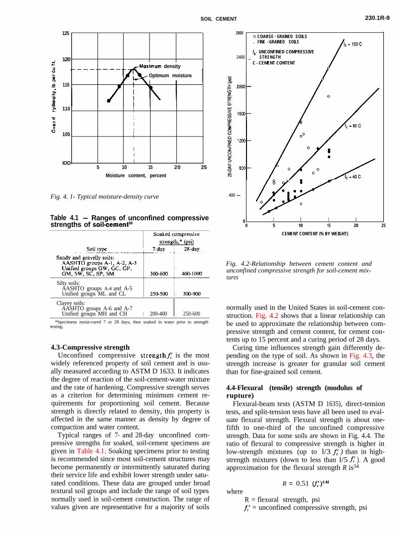
of dry density, although moist density may be used forfield density control. The moisture-density test (ASTMD 558) is used to determine proper moisture contentand density (referred to as optimum moisture contentand maximum dry density) to which the soil-cementmixture is compacted. A typical moisture-density curveis shown in Fig. 4.1. Adding cement to a soil generally
causes some change in both the optimum moisture con-tent and maximum dry density for a given compactiveeffort. However, the direction of this change is notusually predictable. The flocculating action of the ce-ment tends to produce an increase in optimum mois-ture content and a decrease in maximum density, whilethe high specific gravity of the cement relative to thesoil tends to produce a higher density. In general,Shen30 showed that for a given cement content, thehigher the density, the higher the compressive strengthof cohesionless soil-cement mixtures.Prolonged delays between the mixing of soil cementand compaction have an influence on both density andstrength. Studies by West31 showed that a delay of morethan 2 hr between mixing and compaction results in asignificant decrease in both density and compressivestrength. Felt32 had similar findings but also showedthat the effect of time delay was minimized, providedthe mixture was intermittently mixed several times anhour, and the moisture content at the time ‘of compac-tion was at or slightly above optimum.
SOIL CEMENT 230.1R-9
125
.; 120rz
yMaximum density
& Optimum moisture
; 115L
21Ctgz 110 II0I 12 I6 I
105 II
II
IOO- I5 10 15 20 25
Moisture content, percent
Fig. 4. 1- Typical moisture-density curve
Table 4.1 - Ranges of unconfined compressivestrengths of soil-cement33
Silty soils:AASHTO groups A-4 and A-5Unified groups ML and CL
Clayey soils:AASHTO groups A-6 and A-7Unified groups MH and CH I I200-400 250-600
*Specimens moist-cured 7 or 28 days, then soaked in water prior to strengthtesting.
4.3-Compressive strengthUnconfined compressive strengthf,’ is the most
widely referenced property of soil cement and is usu-ally measured according to ASTM D 1633. It indicatesthe degree of reaction of the soil-cement-water mixtureand the rate of hardening. Compressive strength servesas a criterion for determining minimum cement re-quirements for proportioning soil cement. Becausestrength is directly related to density, this property isaffected in the same manner as density by degree ofcompaction and water content.
Typical ranges of 7- and 28-day unconfined com-pressive strengths for soaked, soil-cement specimens aregiven in Table 4.1. Soaking specimens prior to testingis recommended since most soil-cement structures maybecome permanently or intermittently saturated duringtheir service life and exhibit lower strength under satu-rated conditions. These data are grouped under broadtextural soil groups and include the range of soil typesnormally used in soil-cement construction. The range ofvalues given are representative for a majority of soils
400 -
28000 COARSE - GRAINED SOILS. FINE - GRAINED SOILS
f,- UNCONFINED COMPRESSIVE2400 _ STRENGTH
C - CEMENT CONTENT
0 I I I0 5 10 15 20 25
CEMENT CONTENT (% BY WEIGHT)
Fig. 4.2-Relationship between cement content andunconfined compressive strength for soil-cement mix-tures
normally used in the United States in soil-cement con-struction. Fig. 4.2 shows that a linear relationship canbe used to approximate the relationship between com-pressive strength and cement content, for cement con-tents up to 15 percent and a curing period of 28 days.
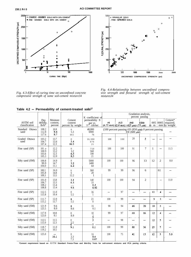
Curing time influences strength gain differently de-pending on the type of soil. As shown in Fig. 4.3, the
strength increase is greater for granular soil cementthan for fine-grained soil cement.4.4-Flexural (tensile) strength (modulus ofrupture)
Flexural-beam tests (ASTM D 1635), direct-tensiontests, and split-tension tests have all been used to eval-uate flexural strength. Flexural strength is about one-fifth to one-third of the unconfined compressivestrength. Data for some soils are shown in Fig. 4.4. Theratio of flexural to compressive strength is higher inlow-strength mixtures (up to l/3 fi ) than in high-strength mixtures (down to less than l/5 ff ). A goodapproximation for the flexural strength R is34
whereR = 0.51 (f,‘)“.“”
R = flexural strength, psif,’ = unconfined compressive strength, psi
230.1 R-l 0 ACI COMMITTEE REPORT
COARSE - GRAINED SOILS WITH 10% CEMENTFINE - GRAINED SOILS WITH 10% CEMENT
10 100 1000
CURING TIME (days)
Fig. 4.3-Effect of curing time on unconfined concretecompressive strength of some soil-cement mixture34
5 0 0o GRANULAR SOILS 0 c. FINE - GRAINED SOILS
01 I I I I0 500 1000 1500 2ooo 2500
UNCONFINED COMPRESSIVE STRENGTH (psi)
Fig. 4.4-Relationship between unconfined compres-sive strength and flexural strength of soil-cementmixtures34
Table 4.2 - Permeability of cement-treated soils17
Gradation analysis,K coefficient of percent passing
Cement permeability ft Cement*content per yr, 005 0005 required,
percent by weight 1 0 - 6 cm/sec (4.7t4mm) (2.o#‘im) (42!4zm) (7;2E) m m mm by weightASTM soil
classification
Drydensity,lb/ft3
Standard Ottawasand
108.2112.8117.6
Moisturecontent,percent
10.8
;:‘:
0 48,800 (100 percent passing #20 (850 pm): 0 percent passing5.3 6900 #30 (600 urn) -
Graded Ottawasand
103.2 13.7104.7 13.6107.4 12.3
10.5 76
0 16 ,300 100 100
1;::4 7 0
21
Fine sand (SP) 101 .o 12.2100.9 13.2103.6 12.3105.3 12.0
0 7 5 0 100 1003.2 560
:::190
21
Silty sand (SM) 100.8 14.999.9 14.7
104.0 15.1
0 5000 100 100
i:f1400
60
Fine sand (SP) 100.1 16.0105.8 14.8109.3 13.5
0 I 360 I 99 996 20
Fine sand (SP) 101.0 13.8106.7 13.3108.2 13.4108.8 13.4
Fine sand (SP) 112.5115.8
11.010.4
12.2 1
0 140 100 100:*: 33
9:6 E2
0 36 - 975.5 5
Fine sand (SP) 111.7 12.0 0 I 23 100 99115.2 11.7 5.5 8
Silty sand (SM) 121.9 9.6125.5 8.0
Silty sand (SM) 117.9 10.8123.0 8.1
Silty sand (SM) 112.5 11.5115.0 12.3
Silty sand (SM) 118.7119.2
11.010.5
Silty sand (SM) 125.0lo,1
0 16 98 948.6 0.1
0 10 99 978.9 2
0 : - 985.5
g.1 i.1 100 99
0 16 100 753.37.3 E7
. .,
28 2-- -
91 7 1 - 11.5
96 13 12 2 8.0
96 6 61 -
94 2 -- 11.0
*Cement requirement based on ASTM Standard Freeze-Thaw and Wet-Dry Tests for soil-cement mixtures and PCA paving criteria.
SOIL CEMENT 230.1 R-11
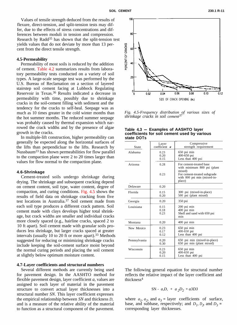
Values of tensile strength deduced from the results offlexure, direct-tension, and split-tension tests may dif-fer, due to the effects of stress concentrations and dif-ferences between moduli in tension and compression.Research by Radd35 has shown that the split-tension testyields values that do not deviate by more than 13 per-cent from the direct tensile strength.
4.5-PermeabilityPermeability of most soils is reduced by the addition
of cement. Table 4.2 summarizes results from labora-tory permeability tests conducted on a variety of soiltypes. A large-scale seepage test was performed by theU.S. Bureau of Reclamation on a section of layeredstairstep soil cement facing at Lubbock RegulatingReservoir in Texas.36 Results indicated a decrease inpermeability with time, possibly due to shrinkagecracks in the soil-cement filling with sediment and thetendency for the cracks to self-heal. Seepage was asmuch as 10 times greater in the cold winter months thanthe hot summer months. The reduced summer seepagewas probably caused by thermal expansion which nar-rowed the crack widths and by the presence of algaegrowth in the cracks.
In multiple-lift construction, higher permeability cangenerally be expected along the horizontal surfaces ofthe lifts than perpendicluar to the lifts. Research byNussbaum23 has shown permeabilities for flow parallelto the compaction plane were 2 to 20 times larger thanvalues for flow normal to the compaction plane.
4.6-ShrinkageCement-treated soils undergo shrinkage during
drying. The shrinkage and subsequent cracking dependon cement content, soil type, water content, degree ofcompaction, and curing conditions. Fig. 4.5 shows the
SIZE OF CRACK OPENING (in.)
Fig. 4.5-Frequency distribution of various sizes ofshrinkage cracks in soil cement37
results of field data on shrinkage cracking from fivetest locations in Australia.37 Soil cement made fromeach soil type produces a different crack pattern. Soilcement made with clays develops higher total shrink-age, but crack widths are smaller and individual cracksmore closely spaced (e.g., hairline cracks, spaced 2 to10 ft apart). Soil cement made with granular soils pro-duces less shrinkage, but larger cracks spaced at greaterintervals (usually 10 to 20 ft or more apart).33 Methodssuggested for reducing or minimizing shrinkage cracksinclude keeping the soil-cement surface moist beyondthe normal curing periods and placing the soil cementat slightly below optimum moisture content.
4.7-Layer coefficients and structural numbersSeveral different methods are currently being used
for pavement design. In the AASHTO method forflexible pavement design, layer coefficient a, values areassigned to each layer of material in the pavementstructure to convert actual layer thicknesses into astructural number SN. This layer coefficient expressesthe empirical relationship between SN and thickness D,and is a measure of the relative ability of the materialto function as a structural component of the pavement.
Table 4.3 - Examples of AASHTO layercoefficients for soil cement used by variousstate DOTs
State
Alabama
Arizona
Delaware 0.20
Florida
Georgia
Louisiana
Montana
New Mexico
Pennsylvania
Wisconsin
Layercoefficient 0
0.230.200.15~____0.28
0.23
0.15 300 psi (mixed-in-place)0.20 500 psi (plant mixed)
0.20 350 psi
0.150.180.23
200 psi min400 psi minShell and sand with 650 psimin
0.20 400 psi min
0.23 650 psi min0.17 400-650 psi0.12 Less than 400 psi
0.20 650 psi min (mixed-in-place)0.30 650 psi min (plant mixed)
0.23 650 psi min0.20 400-650 psi0.15 Less than 400 psi
Compressivestrength requirement
650 psi min 400-650 psiLess than 400 psi
For cement-treated basewith minimum 800 psi (plantmixed)For cement-treated subgradewith 800 psi min (mixed-in-place)
The following general equation for structural numberreflects the relative impact of the layer coefficient andthickness4
SN - a,D, + a 2D2 + a3D3
where a1, a2, and a3 = layer coefficients of surface,base, and subbase, respectively; and D1, D2, and D3 =corresponding layer thicknesses.

230.1 R-l 2 ACI COMMITTEE REPORT
5-MIX PROPORTIONING
Table 5.1 - PCA criteria for soil-cement as indicated by wet-dry andfreeze-thaw durability tests1
AASHTO Unified soil Maximum allowable weightsoil group group loss, percent
A-l-a GW, GP, GM, SW, SP, SM 14
A-l-b GM, GP, SM, SP 14
A-2 GM, GC, SM, SC 14*
A-3 SP 14
A-4 CL, ML 10
A-5 ML, MH, CH 10
A-6 CL, CH 7
A-7 OH, MH, CH 7*10 percent is maximum allowable weight loss for A-2-6 and A-2-7 soils.Additional criteria
1. Maximum volume changes during durability test should be less than 2 percent of the initial volume.2. Maximum water content during the test should be less than the quantity required to saturate the sample at the
time of molding.3. Compressive strength should increase with age of specimen.4. The cement content determined as adequate for pavement, using the PCA criteria above, will be adequate for
soil-cement slope protection that is 5 ft or more below the minimum water elevation. For soil cement that ishigher than that elevation, the cement content should be increased two percentage points.
The layer coefficients are actually the average of a setof multiple regression coefficients, which indicate theeffect of the wearing course, the base course, and thesubbase on the pavement’s performance. Typical soil-cement layer coefficient a, values used by state depart-ments of transportation are given in Table 4.3.
5.1-GeneralThe principal structural requirements of a hardened
soil-cement mixture are based on adequate strength anddurability. For water resource applications such as lin-ers, permeability may be the principal requirement. Ta-ble 3.1 indicates typical cement contents for pavementapplications. Detailed test procedures for evaluatingmix proportions are given in the Portland Cement As-sociation Soil-Cement Laboratory Handbook1 and bythe following ASTM test standards:
ASTM D 558
ASTM D 559
ASTM D 560
ASTM D 1557
ASTM D 1632
ASTM D 1633
ASTM D 2901
Test for Moisture-Density Relations ofSoil-Cement MixturesWetting-and-Drying Tests of Com-pacted Soil-Cement MixturesFreezing-and-Thawing Tests of Com-pacted Soil-Cement MixturesMoisture-Density Relations of Soilsand Soil Aggregate Mixtures Using 10-lb Rammer and 18-in. DropMaking and Curing Soil-CementCompression and Flexure Test Speci-mens in the LaboratoryTest for Compression Strength ofMolded Soil-Cement CylindersTest for Cement Content of FreshlyMixed Soil-Cement
5.2-ProportioningVarious criteria are used by different organizations to
determine acceptable mix proportions. The Portland
Table 5.2 - USACE durability requirement38
Maximum allowable weight loss afterType of soil 12 wet-dry or freeze-thaw cycles,stabilized* percent of initial specimen weight
Granular, PI< 10 11Granular, PI> 10Silt :Clays 6
*Refer to MIL-STD-619B and MIL-STD-621A, U.S. Army corps of Engi-neers.
Table 5.3 - USACE minimum unconfinedcompressive strength criteria38
Minimum unconfined compressive
Flexible pavement Rigid pavement,,:““m
Subbase course, select material or
Cement Association (PCA) criteria are summarized inTable 5.1. Cement contents sufficient to prevent weightlosses greater than the values indicated after 12 cyclesof wetting-drying-brushing or freezing-thawing-brush-ing are considered adequate to produce a durable soilcement.
The U.S. Army Corps of Engineers (USACE) fol-lows its technical manual, “Soil Stabilization for Pave-ments,” TM 5-822-4.38 The durability and strength re-quirements for portland cement stabilization are givenin Tables 5.2 and 5.3, respectively. USACE requiresthat both criteria be met before a stabilized layer can beused to reduce the required surface thickness in the de-sign of a pavement system. USACE frequently in-creases the cement content by 1 or 2 percent to accountfor field variations. For bank protection, USACE hasan unnumbered draft Engineer Technical letter for in-terim guidance. 39
The U.S. Bureau of Reclamation (USBR) design cri-teria for soil-cement slope protection on dams allowmaximum losses during freeze-thaw and wet-dry dura-
SOIL CEMENT 230.1 R-13
5.3-Special considerations5.3.1 Strength versus durability-In many soil-ce-
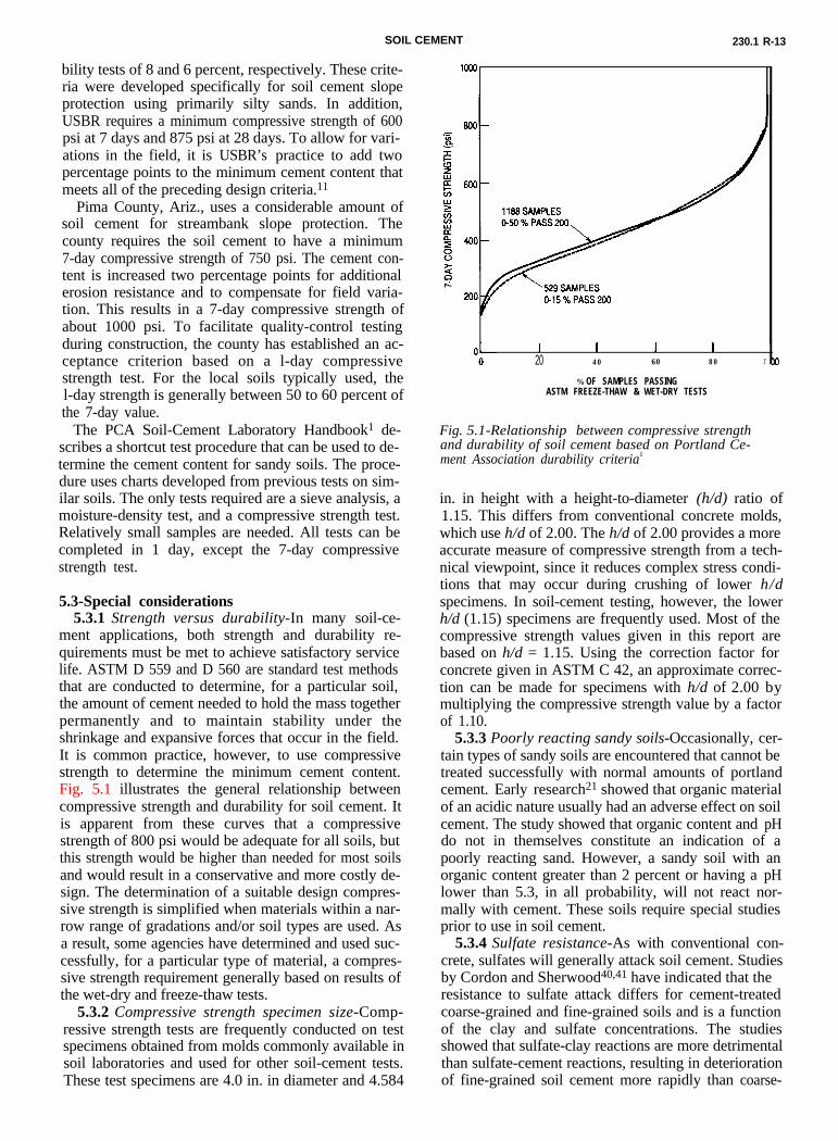
ment applications, both strength and durability re-quirements must be met to achieve satisfactory servicelife. ASTM D 559 and D 560 are standard test methodsthat are conducted to determine, for a particular soil,the amount of cement needed to hold the mass togetherpermanently and to maintain stability under theshrinkage and expansive forces that occur in the field.It is common practice, however, to use compressivestrength to determine the minimum cement content.Fig. 5.1 illustrates the general relationship between
I I I I20 40 60 80
% OF SAMPLES PASSINGASTM FREEZE-THAW & WET-DRY TESTS
1'
Fig. 5.1-Relationship between compressive strengthand durability of soil cement based on Portland Ce-ment Association durability criteria1
compressive strength and durability for soil cement. Itis apparent from these curves that a compressivestrength of 800 psi would be adequate for all soils, butthis strength would be higher than needed for most soilsand would result in a conservative and more costly de-sign. The determination of a suitable design compres-sive strength is simplified when materials within a nar-row range of gradations and/or soil types are used. Asa result, some agencies have determined and used suc-cessfully, for a particular type of material, a compres-sive strength requirement generally based on results ofthe wet-dry and freeze-thaw tests.
bility tests of 8 and 6 percent, respectively. These crite-ria were developed specifically for soil cement slopeprotection using primarily silty sands. In addition,USBR requires a minimum compressive strength of 600psi at 7 days and 875 psi at 28 days. To allow for vari-ations in the field, it is USBR’s practice to add twopercentage points to the minimum cement content thatmeets all of the preceding design criteria.11
Pima County, Ariz., uses a considerable amount ofsoil cement for streambank slope protection. Thecounty requires the soil cement to have a minimum7-day compressive strength of 750 psi. The cement con-tent is increased two percentage points for additionalerosion resistance and to compensate for field varia-tion. This results in a 7-day compressive strength ofabout 1000 psi. To facilitate quality-control testingduring construction, the county has established an ac-ceptance criterion based on a l-day compressivestrength test. For the local soils typically used, thel-day strength is generally between 50 to 60 percent ofthe 7-day value.
The PCA Soil-Cement Laboratory Handbook1 de-scribes a shortcut test procedure that can be used to de-termine the cement content for sandy soils. The proce-dure uses charts developed from previous tests on sim-ilar soils. The only tests required are a sieve analysis, amoisture-density test, and a compressive strength test.Relatively small samples are needed. All tests can becompleted in 1 day, except the 7-day compressivestrength test.
5.3.2 Compressive strength specimen size-Comp-ressive strength tests are frequently conducted on testspecimens obtained from molds commonly available insoil laboratories and used for other soil-cement tests.These test specimens are 4.0 in. in diameter and 4.584
in. in height with a height-to-diameter (h/d) ratio of1.15. This differs from conventional concrete molds,which use h/d of 2.00. The h/d of 2.00 provides a moreaccurate measure of compressive strength from a tech-nical viewpoint, since it reduces complex stress condi-tions that may occur during crushing of lower h/dspecimens. In soil-cement testing, however, the lowerh/d (1.15) specimens are frequently used. Most of thecompressive strength values given in this report arebased on h/d = 1.15. Using the correction factor forconcrete given in ASTM C 42, an approximate correc-tion can be made for specimens with h/d of 2.00 bymultiplying the compressive strength value by a factorof 1.10.
5.3.3 Poorly reacting sandy soils-Occasionally, cer-tain types of sandy soils are encountered that cannot betreated successfully with normal amounts of portlandcement. Early research21 showed that organic materialof an acidic nature usually had an adverse effect on soilcement. The study showed that organic content and pHdo not in themselves constitute an indication of apoorly reacting sand. However, a sandy soil with anorganic content greater than 2 percent or having a pHlower than 5.3, in all probability, will not react nor-mally with cement. These soils require special studiesprior to use in soil cement.
5.3.4 Sulfate resistance-As with conventional con-crete, sulfates will generally attack soil cement. Studiesby Cordon and Sherwood40,41 have indicated that theresistance to sulfate attack differs for cement-treatedcoarse-grained and fine-grained soils and is a functionof the clay and sulfate concentrations. The studiesshowed that sulfate-clay reactions are more detrimentalthan sulfate-cement reactions, resulting in deteriorationof fine-grained soil cement more rapidly than coarse-

230.1R-14 ACI COMMITTEE REPORT
grained soil cement. Also, increasing the cement con-tent of soil-cement mixtures may be more beneficialthan changing to a sulfate-resistant type of cement.
6-CONSTRUCTION6.1-General
In the construction of soil cement, the objective is toobtain a thoroughly mixed, adequately compacted, andcured material. Several references are available8,13,42-44
that discuss soil-cement construction methods for var-ious applications. Specifications on soil-cement con-struction are also readily available.45-47
Soil cement should not be mixed or placed when thesoil or subgrade is frozen or when the air temperatureis below 45 F. However, a common practice is to pro-ceed with construction when the air temperature is atleast 40 F and rising. When the air temperature is ex-pected to reach the freezing point, the soil cementshould be protected from freezing for at least 7 days.Soil-cement construction typically requires the additionof water equivalent to 1 to 1 l/ in. of rain; therefore, a
Fig. 6. 1 Transverse single-shaft mixer processingcement in place; multiple passes are required
soil
Fig. 6.2-Mixing chamber of a transverse single-shaftmixer
light rainfall should not delay construction. However,a heavy rainfall that occurs after most of the water hasbeen added can be detrimental. If rain falls during ce-ment-spreading operations, spreading should bestopped and the cement already spread should bequickly mixed into the soil mass. Compaction shouldbegin immediately and continue until the soil cement iscompletely compacted. After the mixture has beencompacted, rain usually will not harm it.
6.2-Materials handling and mixingSoil cement is either mixed in place or mixed in a
central mixing plant. The typical types of mixingequipment are:
1. In-place traveling mixersa. Transverse single-shaft mixerb. Windrow-type pugmill
2. Central mixing planta. Continuous-flow-type pugmillb. Batch-type pugmillc. Rotary-drum mixer
6.2.1 Mixed in place-- Mixing operations withsubgrade materials are performed with transverse sin-gle-shaft-type mixers (Fig. 6.1 and 6.2). Mixing withborrow materials may be performed with single-shaft orwindrow-type pugmill mixers (Fig. 6.3). Almost all
Fig. 6.3- Windrow-type traveling pugmill mixing soilcement from windrows of soil material
types of soil, from granular to fine-grained, can be ad-equately pulverized and mixed with transverse single-shaft mixers. Windrow-type pugmills are generally lim-ited to nonplastic to slightly plastic granular soils.
6.2.1.1 Soil preparation-During grading opera-tions, all soft or wet subgrade areas are located andcorrected. All deleterious material such as stumps,roots, organic soils, and aggregates larger than 3 in.should be removed. For single-shaft mixers, the soil isshaped to the approximate final lines and grades priorto mixing. Proper moisture content aids in pulveriza-tion. For granular soils, mixing at less than optimummoisture content minimizes the chances for cementballs to form. For fine-grained soils, moisture contentnear optimum may be necessary for effective pulveri-zation.
SOILNCEMENT 230.1 R-15
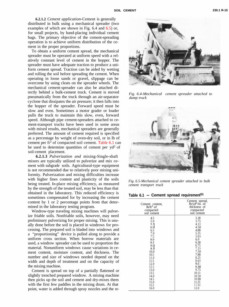
6.2.1.2 Cement application-Cement is generallydistributed in bulk using a mechanical spreader (twoexamples of which are shown in Fig. 6.4 and 6.5) or,
Fig. 6.4-Mechanical cement spreader attached todump truck
Fig. 6.5-Mechanical cement spreader attached to bulkcement transport truck
for small projects, by hand-placing individual cementbags. The primary objective of the cement-spreadingoperation is to achieve uniform distribution of the ce-ment in the proper proportions.
To obtain a uniform cement spread, the mechanicalspreader must be operated at uniform speed with a rel-atively constant level of cement in the hopper. Thespreader must have adequate traction to produce a uni-form cement spread. Traction can be aided by wettingand rolling the soil before spreading the cement. Whenoperating in loose sands or gravel, slippage can beovercome by using cleats on the spreader wheels. Themechanical cement-spreader can also be attached di-rectly behind a bulk-cement truck. Cement is movedpneumatically from the truck through an air-separatorcyclone that dissipates the air pressure; it then falls intothe hopper of the spreader. Forward speed must beslow and even. Sometimes a motor grader or loaderpulls the truck to maintain this slow, even, forwardspeed. Although pipe cement-spreaders attached to ce-ment-transport trucks have been used in some areaswith mixed results, mechanical spreaders are generallypreferred. The amount of cement required is specifiedas a percentage by weight of oven-dry soil, or in lb ofcement per ft3 of compacted soil cement. Table 6.1 can
Table 6.1 - Cement spread requirement51
Cement content,lb/ft3 of
compactedsoil cement
Cement spread,lb/yd2/in. ofthickness ofcompactedsoil cement
4.55.0
i-i6.57.07.5
K
E10.010.511.011.512.012.513.013.514.014.515.015.516.0
3.383.754.134.504.885.255.636.06.386.757.137.507.888.258.63
E89.75
10.1310.5010.8811.251 1.6312.0
be used to determine quantities of cement per yd2 ofsoil-cement placement.
6.2.1.3 Pulverization and mixing-Single-shaftmixers are typically utilized to pulverize and mix ce-ment with subgrade soils. Agricultural-type equipmentis not recommended due to relatively poor mixing uni-formity. Pulverization and mixing difficulties increasewith higher fines content and plasticity of the soilsbeing treated. In-place mixing efficiency, as measuredby the strength of the treated soil, may be less than thatobtained in the laboratory. This reduced efficiency issometimes compensated for by increasing the cementcontent by 1 or 2 percentage points from that deter-mined in the laboratory testing program.
Windrow-type traveling mixing machines will pulver-ize friable soils. Nonfriable soils, however, may needpreliminary pulverizing for proper mixing. This is usu-ally done before the soil is placed in windrows for pro-cessing. The prepared soil is bladed into windrows anda “proportioning” device is pulled along to provide auniform cross section. When borrow materials areused, a windrow spreader can be used to proportion thematerial. Nonuniform windrows cause variations in ce-ment content, moisture content, and thickness. Thenumber and size of windrows needed depend on thewidth and depth of treatment and on the capacity ofthe mixing machine.
Cement is spread on top of a partially flattened orslightly trenched prepared windrow. A mixing machinethen picks up the soil and cement and dry-mixes themwith the first few paddles in the mixing drum. At thatpoint, water is added through spray nozzles and the re-
230.1 R-16 ACI COMMITTEE REPORT
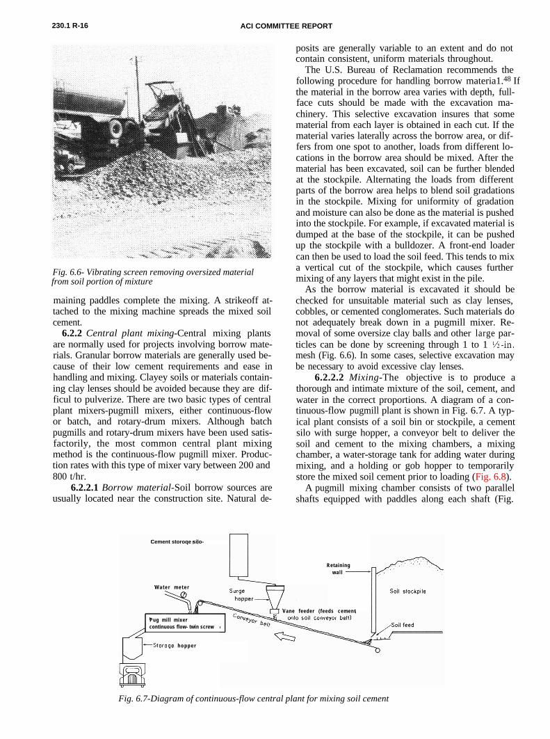
Fig. 6.6- Vibrating screen removing oversized materialfrom soil portion of mixture
maining paddles complete the mixing. A strikeoff at-tached to the mixing machine spreads the mixed soilcement.
6.2.2 Central plant mixing-Central mixing plantsare normally used for projects involving borrow mate-rials. Granular borrow materials are generally used be-cause of their low cement requirements and ease inhandling and mixing. Clayey soils or materials contain-ing clay lenses should be avoided because they are dif-ficul to pulverize. There are two basic types of centralplant mixers-pugmill mixers, either continuous-flowor batch, and rotary-drum mixers. Although batchpugmills and rotary-drum mixers have been used satis-factorily, the most common central plant mixingmethod is the continuous-flow pugmill mixer. Produc-tion rates with this type of mixer vary between 200 and800 t/hr.
6.2.2.1 Borrow material-Soil borrow sources areusually located near the construction site. Natural de-
posits are generally variable to an extent and do notcontain consistent, uniform materials throughout.
The U.S. Bureau of Reclamation recommends thefollowing procedure for handling borrow materia1.48 Ifthe material in the borrow area varies with depth, full-face cuts should be made with the excavation ma-chinery. This selective excavation insures that somematerial from each layer is obtained in each cut. If thematerial varies laterally across the borrow area, or dif-fers from one spot to another, loads from different lo-cations in the borrow area should be mixed. After thematerial has been excavated, soil can be further blendedat the stockpile. Alternating the loads from differentparts of the borrow area helps to blend soil gradationsin the stockpile. Mixing for uniformity of gradationand moisture can also be done as the material is pushedinto the stockpile. For example, if excavated material isdumped at the base of the stockpile, it can be pushedup the stockpile with a bulldozer. A front-end loadercan then be used to load the soil feed. This tends to mixa vertical cut of the stockpile, which causes furthermixing of any layers that might exist in the pile.
As the borrow material is excavated it should bechecked for unsuitable material such as clay lenses,cobbles, or cemented conglomerates. Such materials donot adequately break down in a pugmill mixer. Re-moval of some oversize clay balls and other large par-ticles can be done by screening through 1 to 1 %-in.mesh (Fig. 6.6). In some cases, selective excavation maybe necessary to avoid excessive clay lenses.
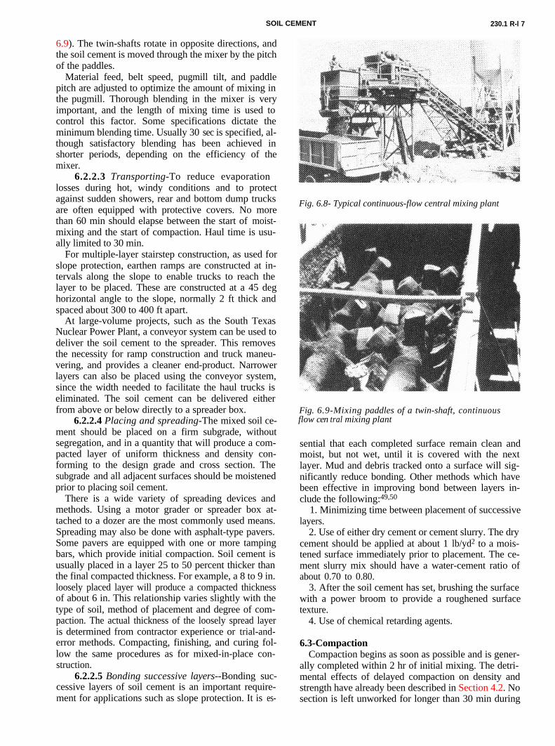
6.2.2.2 Mixing-The objective is to produce athorough and intimate mixture of the soil, cement, andwater in the correct proportions. A diagram of a con-tinuous-flow pugmill plant is shown in Fig. 6.7. A typ-
Cement storoqe silo-
W a t e r m e t e r
Pug mil l mixercontinuous flow- twin screw
Vane feeder ( feeds cement
-Storage h o p p e r
Retainingwa l l -
Fig. 6.7-Diagram of continuous-flow central plant for mixing soil cement
ical plant consists of a soil bin or stockpile, a cementsilo with surge hopper, a conveyor belt to deliver thesoil and cement to the mixing chambers, a mixingchamber, a water-storage tank for adding water duringmixing, and a holding or gob hopper to temporarilystore the mixed soil cement prior to loading (Fig. 6.8).
A pugmill mixing chamber consists of two parallelshafts equipped with paddles along each shaft (Fig.
SOIL CEMENT 230.1 R-l 7
Fig. 6.8- Typical continuous-flow central mixing plant
6.9). The twin-shafts rotate in opposite directions, and
Fig. 6.9-Mixing paddles of a twin-shaft, continuousflow cen tral mixing plant
the soil cement is moved through the mixer by the pitchof the paddles.
Material feed, belt speed, pugmill tilt, and paddlepitch are adjusted to optimize the amount of mixing inthe pugmill. Thorough blending in the mixer is veryimportant, and the length of mixing time is used tocontrol this factor. Some specifications dictate theminimum blending time. Usually 30 sec is specified, al-though satisfactory blending has been achieved inshorter periods, depending on the efficiency of themixer.
6.2.2.3 Transporting-To reduce evaporationlosses during hot, windy conditions and to protectagainst sudden showers, rear and bottom dump trucksare often equipped with protective covers. No morethan 60 min should elapse between the start of moist-mixing and the start of compaction. Haul time is usu-ally limited to 30 min.
For multiple-layer stairstep construction, as used forslope protection, earthen ramps are constructed at in-tervals along the slope to enable trucks to reach thelayer to be placed. These are constructed at a 45 deghorizontal angle to the slope, normally 2 ft thick andspaced about 300 to 400 ft apart.
At large-volume projects, such as the South TexasNuclear Power Plant, a conveyor system can be used todeliver the soil cement to the spreader. This removesthe necessity for ramp construction and truck maneu-vering, and provides a cleaner end-product. Narrowerlayers can also be placed using the conveyor system,since the width needed to facilitate the haul trucks iseliminated. The soil cement can be delivered eitherfrom above or below directly to a spreader box.
6.2.2.4 Placing and spreading-The mixed soil ce-ment should be placed on a firm subgrade, withoutsegregation, and in a quantity that will produce a com-pacted layer of uniform thickness and density con-forming to the design grade and cross section. Thesubgrade and all adjacent surfaces should be moistenedprior to placing soil cement.
There is a wide variety of spreading devices andmethods. Using a motor grader or spreader box at-tached to a dozer are the most commonly used means.Spreading may also be done with asphalt-type pavers.Some pavers are equipped with one or more tampingbars, which provide initial compaction. Soil cement isusually placed in a layer 25 to 50 percent thicker thanthe final compacted thickness. For example, a 8 to 9 in.loosely placed layer will produce a compacted thicknessof about 6 in. This relationship varies slightly with thetype of soil, method of placement and degree of com-paction. The actual thickness of the loosely spread layeris determined from contractor experience or trial-and-error methods. Compacting, finishing, and curing fol-low the same procedures as for mixed-in-place con-struction.
6.2.2.5 Bonding successive layers--Bonding suc-cessive layers of soil cement is an important require-ment for applications such as slope protection. It is es-
sential that each completed surface remain clean andmoist, but not wet, until it is covered with the nextlayer. Mud and debris tracked onto a surface will sig-nificantly reduce bonding. Other methods which havebeen effective in improving bond between layers in-clude the following:49,50
1. Minimizing time between placement of successivelayers.
2. Use of either dry cement or cement slurry. The drycement should be applied at about 1 lb/yd2 to a mois-tened surface immediately prior to placement. The ce-ment slurry mix should have a water-cement ratio ofabout 0.70 to 0.80.
3. After the soil cement has set, brushing the surfacewith a power broom to provide a roughened surfacetexture.
4. Use of chemical retarding agents.
6.3-Compaction’Compaction begins as soon as possible and is gener-
ally completed within 2 hr of initial mixing. The detri-mental effects of delayed compaction on density andstrength have already been described in Section 4.2. Nosection is left unworked for longer than 30 min during
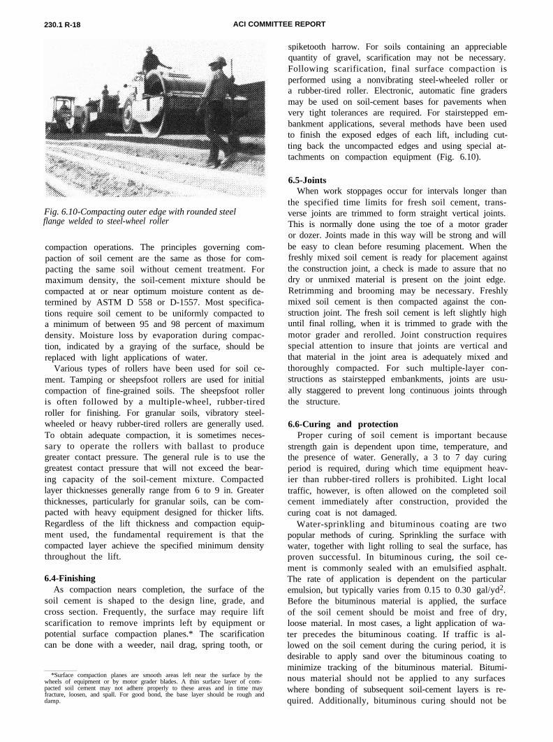
230.1 R-18 ACI COMMITTEE REPORT
Fig. 6.10-Compacting outer edge with rounded steelflange welded to steel-wheel roller
compaction operations. The principles governing com-paction of soil cement are the same as those for com-pacting the same soil without cement treatment. Formaximum density, the soil-cement mixture should becompacted at or near optimum moisture content as de-termined by ASTM D 558 or D-1557. Most specifica-tions require soil cement to be uniformly compacted toa minimum of between 95 and 98 percent of maximumdensity. Moisture loss by evaporation during compac-tion, indicated by a graying of the surface, should bereplaced with light applications of water.
Various types of rollers have been used for soil ce-ment. Tamping or sheepsfoot rollers are used for initialcompaction of fine-grained soils. The sheepsfoot rolleris often followed by a multiple-wheel, rubber-tiredroller for finishing. For granular soils, vibratory steel-wheeled or heavy rubber-tired rollers are generally used.To obtain adequate compaction, it is sometimes neces-sary to operate the rollers with ballast to producegreater contact pressure. The general rule is to use thegreatest contact pressure that will not exceed the bear-ing capacity of the soil-cement mixture. Compactedlayer thicknesses generally range from 6 to 9 in. Greaterthicknesses, particularly for granular soils, can be com-pacted with heavy equipment designed for thicker lifts.Regardless of the lift thickness and compaction equip-ment used, the fundamental requirement is that thecompacted layer achieve the specified minimum densitythroughout the lift.
6.4-FinishingAs compaction nears completion, the surface of the
soil cement is shaped to the design line, grade, andcross section. Frequently, the surface may require liftscarification to remove imprints left by equipment orpotential surface compaction planes.* The scarificationcan be done with a weeder, nail drag, spring tooth, or
*Surface compaction planes are smooth areas left near the surface by thewheels of equipment or by motor grader blades. A thin surface layer of com-pacted soil cement may not adhere properly to these areas and in time mayfracture, loosen, and spall. For good bond, the base layer should be rough anddamp.
spiketooth harrow. For soils containing an appreciablequantity of gravel, scarification may not be necessary.Following scarification, final surface compaction isperformed using a nonvibrating steel-wheeled roller ora rubber-tired roller. Electronic, automatic fine gradersmay be used on soil-cement bases for pavements whenvery tight tolerances are required. For stairstepped em-bankment applications, several methods have been usedto finish the exposed edges of each lift, including cut-ting back the uncompacted edges and using special at-tachments on compaction equipment (Fig. 6.10).
6.5-JointsWhen work stoppages occur for intervals longer than
the specified time limits for fresh soil cement, trans-verse joints are trimmed to form straight vertical joints.This is normally done using the toe of a motor graderor dozer. Joints made in this way will be strong and willbe easy to clean before resuming placement. When thefreshly mixed soil cement is ready for placement againstthe construction joint, a check is made to assure that nodry or unmixed material is present on the joint edge.Retrimming and brooming may be necessary. Freshlymixed soil cement is then compacted against the con-struction joint. The fresh soil cement is left slightly highuntil final rolling, when it is trimmed to grade with themotor grader and rerolled. Joint construction requiresspecial attention to insure that joints are vertical andthat material in the joint area is adequately mixed andthoroughly compacted. For such multiple-layer con-structions as stairstepped embankments, joints are usu-ally staggered to prevent long continuous joints throughthe structure.
6.6-Curing and protectionProper curing of soil cement is important because
strength gain is dependent upon time, temperature, andthe presence of water. Generally, a 3 to 7 day curingperiod is required, during which time equipment heav-ier than rubber-tired rollers is prohibited. Light localtraffic, however, is often allowed on the completed soilcement immediately after construction, provided thecuring coat is not damaged.
Water-sprinkling and bituminous coating are twopopular methods of curing. Sprinkling the surface withwater, together with light rolling to seal the surface, hasproven successful. In bituminous curing, the soil ce-ment is commonly sealed with an emulsified asphalt.The rate of application is dependent on the particularemulsion, but typically varies from 0.15 to 0.30 gal/yd2.Before the bituminous material is applied, the surfaceof the soil cement should be moist and free of dry,loose material. In most cases, a light application of wa-ter precedes the bituminous coating. If traffic is al-lowed on the soil cement during the curing period, it isdesirable to apply sand over the bituminous coating tominimize tracking of the bituminous material. Bitumi-nous material should not be applied to any surfaceswhere bonding of subsequent soil-cement layers is re-quired. Additionally, bituminous curing should not be
SOIL CEMENT 230.1R-19
applied on soil-cement linings for ponds or reservoirswhich will be used to hold aquatic life.
Curing can also be accomplished by covering thecompacted soil cement with wet burlap, plastic tarps, ormoist earth.
Soil cement must be protected from freezing duringthe curing period. Insulation blankets, straw, or soilcover are commonly used.
7-QUALITY CONTROL TESTING ANDINSPECTION
7.1-GeneralQuality control is essential to assure that the final
product will be adequate for its intended use. Addi-tionally, it must assure that the contractor has per-formed work in accordance with the plans and specifi-cations. Field inspection of soil-cement constructioninvolves controlling the following factors:
1. Pulverization/gradation2. Cement content3. Moisture content4. Mixing uniformity5. Compaction6. Lift thickness and surface tolerance7. Curing
References 48 and 51 provide excellent information on
quality-control inspection and testing of soil cementduring construction.7.2-Pulverization (mixed in place)Most soils require minimum pulverization before
processing starts. However, the heavier clay soils re-quire a considerable amount of preliminary work. Thekeys to pulverization of clayey soils are proper mois-ture control and proper equipment. Since clayey soilscannot be adequately pulverized in a central plant, theiruse is restricted to mixed-in-place construction.
PCA specifications45,466require that, at the comple-tion of moist mixing, 80 percent of the soil-cementmixture pass the No. 4 sieve and 100 percent pass thel-in. sieve, exclusive of gravel or stone retained on thesesieves. This is checked by doing a pulverization test,which consists of screening a representative sample ofsoil cement through a No. 4 sieve. Any gravel or stoneretained on the sieve is picked out and discarded. Theclay lumps retained and the pulverized soil passing theNo. 4 sieve are weighed separately and their dry weightsdetermined. The degree of pulverization is calculated asfollow51
Dry weight of soil-cementmixture passing
Percent No. 4 sievepulverization = Dry weight of total
x 100
sample exclusive of gravelretained on No. 4 sieve
Note that for practical purposes, wet weights of mate-rials are often used instead of the corrected dry weights.The wet-weight measurements are reasonably accurate
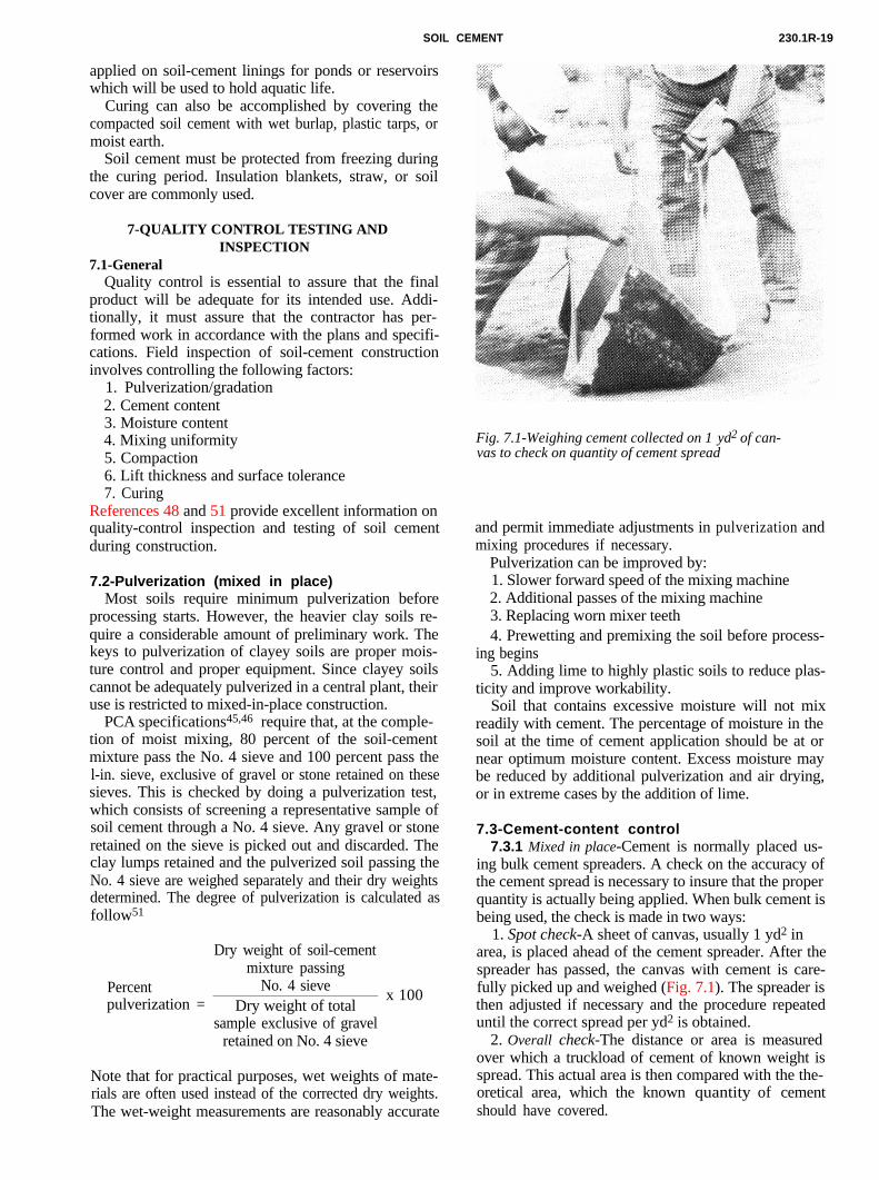
Fig. 7.1-Weighing cement collected on 1 yd2 of can-vas to check on quantity of cement spread
and permit immediate adjustments in pulverization andmixing procedures if necessary.
Pulverization can be improved by:1. Slower forward speed of the mixing machine2. Additional passes of the mixing machine3. Replacing worn mixer teeth4. Prewetting and premixing the soil before process-
ing begins5. Adding lime to highly plastic soils to reduce plas-
ticity and improve workability.Soil that contains excessive moisture will not mix
readily with cement. The percentage of moisture in thesoil at the time of cement application should be at ornear optimum moisture content. Excess moisture maybe reduced by additional pulverization and air drying,or in extreme cases by the addition of lime.
7.3-Cement-content control7.3.1 Mixed in place-Cement is normally placed us-
ing bulk cement spreaders. A check on the accuracy ofthe cement spread is necessary to insure that the properquantity is actually being applied. When bulk cement isbeing used, the check is made in two ways:
1. Spot check-A sheet of canvas, usually 1 yd2 inarea, is placed ahead of the cement spreader. After thespreader has passed, the canvas with cement is care-fully picked up and weighed (Fig. 7.1). The spreader isthen adjusted if necessary and the procedure repeateduntil the correct spread per yd2 is obtained.
2. Overall check-The distance or area is measuredover which a truckload of cement of known weight isspread. This actual area is then compared with the the-oretical area, which the known quantity of cementshould have covered.
230.1R-20 ACI COMMITTEE REPORT
Generally, the spreader is first adjusted at the start ofconstruction after checking the cement spread per yd2
with the canvas. Then slight adjustments are made af-ter checking the distance over which each truckload isspread. It is important to keep a continuous check oncement-spreading operations.
On small jobs, bagged cement is sometimes used. Thebags should be spaced at approximately equal trans-verse and longitudinal intervals that will insure theproper percentage of cement. Positions can be spottedby flags or markers fastened to ropes at proper inter-vals to mark the transverse and longitudinal rows.
7.3.2 Central mixing plant-In a central mixing-plantoperation, it is necessary to proportion the cement andsoil before they enter the mixing chamber. When soilcement is mixed in a batch-type pugmill or rotary-drummixing plant, the proper quantities of soil, cement, andwater for each batch are weighed before being trans-ferred to the mixer. These types of plants are calibratedsimply by checking the accuracy of the weight scales.
For a continuous-flow mixing plant, two methods ofplant calibration may be used.
1. With the plant operating, soil is run through theplant for a given period of time and collected in atruck. During this same period, cement is diverted di-rectly from the cement feeder into a truck or suitablecontainer. Both the soil and cement are weighed andthe cement feeder is adjusted until the correct amountof cement is discharged.
2. The plant is operated with only soil feeding ontothe main conveyor belt. The soil on a selected length ofconveyor belt is collected and its dry weight is deter-mined. The plant is then operated with only cementfeeding onto the main conveyor belt. The cement feederis adjusted until the correct amount of cement is beingdischarged.
It may be necessary to calibrate the mixing plant atvarious operating speeds. Typically, plants are cali-brated daily at the beginning of a project, and periodi-cally thereafter, to assure that no change has occurredin the operation.
7.4-Moisture contentProper moisture content is necessary for adequate
compaction and for hydration of the cement. Theproper moisture content of the cement-treated soil isdetermined by the moisture-density test (ASTM D 558or D 1557). This moisture content, known as optimummoisture, is used as a guide for field control duringconstruction. The approximate percentage of wateradded to the soil is equal to the difference between theoptimum moisture content and the moisture content ofthe soil. About 2 percent additional moisture may beadded to account for hydration of the dry cement andfor evaporation that normally occurs during process-ing.
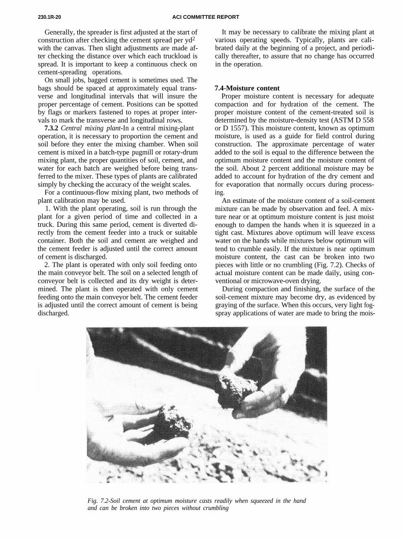
An estimate of the moisture content of a soil-cementmixture can be made by observation and feel. A mix-ture near or at optimum moisture content is just moistenough to dampen the hands when it is squeezed in atight cast. Mixtures above optimum will leave excesswater on the hands while mixtures below optimum willtend to crumble easily. If the mixture is near optimummoisture content, the cast can be broken into twopieces with little or no crumbling (Fig. 7.2). Checks of
Fig. 7.2-Soil cement at optimum moisture casts readily when squeezed in the handand can be broken into two pieces without crumbling
actual moisture content can be made daily, using con-ventional or microwave-oven drying.
During compaction and finishing, the surface of thesoil-cement mixture may become dry, as evidenced bygraying of the surface. When this occurs, very light fog-spray applications of water are made to bring the mois-
SOIL CEMENT 230.1 -21
ture content back to optimum. Proper moisture con-tent of the compacted soil cement is evidenced by asmooth, moist, tightly knit, compacted surface free ofcracks and surface dusting.
7.5-Mixing uniformity7.5.1 Mixed in place-A thorough mixture of pul-
verized soil, cement, and water is necessary to makehigh-quality soil cement. Where heavy clay soils arebeing treated, pulverization tests should be conductedprior to compaction as described in Section 7.2. Theuniformity of all soil-cement mixtures is checked bydigging trenches or a series of holes at regular intervalsfor the full depth of treatment and then inspecting thecolor of the exposed material. When the mixture is ofuniform color and texture from top to bottom, themixture is satisfactory. A mixture that has a streakedappearance has not been mixed sufficiently. Depth ofmixing is usually checked at the same time as uniform-ity. Routine depth checks are made during mixing op-erations and following compaction to assure that thespecified thickness is attained. Following compaction,a final check on mixing uniformity and depth can bemade using a 2 percent solution of phenolphthalein.The phenolphthalein solution can be squirted down theside of a freshly cut face of newly compacted soil ce-ment. The soil cement will turn pinkish-red while theuntreated soil and subgrade material (unless it is cal-cium-rich soil) will retain its natural color.
7.5.2 Central mix plant- For central-plant-mixedsoil cement, the uniformity is usually checked visuallyat the mixing plant. It can also be checked at the place-ment area in a manner similar to the method used formixed-in-place construction. The mixing time necessaryto achieve an intimate uniform mixture will depend onthe soil gradation and mixing plant used. Usually 20 to30 sec of mixing are required.
7.6-CompactionThe soil-cement mixture is compacted at or near op-
timum moisture content to some specified minimumpercent of maximum density. Generally, the density re-quirements range from 95 to 100 percent of the maxi-mum density of the cement-treated soil as determinedby the moisture-density test (ASTM D 558 or D 1557).The most common methods for determining in-placedensity are:
1. Nuclear method (ASTM D 2922 and D 3017)2. Sand-cone method (ASTM D 1556)3. Balloon method (ASTM D 2167)In-place densities are determined daily at frequencies
that vary widely, depending on the application. Thetests are made immediately after rolling. Comparing in-place densities with the results of maximum density re-sults from the field moisture-density test indicates anyadjustments in compaction procedures that may be re-quired to insure compliance with job specifications.
7.7-Lift thickness and surface tolerance7.7.1 Lift thickness- Compacted lift thickness is
usually checked when performing field-density checks
with the sand cone or the balloon method, or by dig-ging small holes in the fresh soil cement to determinethe bottom of treatment. Thickness can also be checkedby coring the hardened soil cement. This provides asmall diameter core for measuring thickness and forstrength testing if required. Lift thickness is usuallymore critical for pavements than for embankment ap-plications. For pavements, the U.S. Army Corps ofEngineers typically tests thickness with a 3 in. diametercore for every 500 yd2 of soil cement. Other agencies,such as Caltrans, require that thickness measurementsbe taken at intervals not to exceed 1000 linear ft.
7.7.2 Surface tolerance-Surface tolerances are usu-ally not specified for soil-cement embankment applica-tions, although lift elevation may be monitored withsurvey techniques. The U.S. Bureau of Reclamationcontrols only the soil-cement embankment crest roadelevation to within 0.01 ft of design grade. To providea reasonably smooth surface for pavement sections,smoothness is usually measured with a 10-ft or 12-ftstraightedge, or with surveying equipment. The U.S.Army Corps of Engineers typically requires that devia-tions from the plane of a soil-cement base course notexceed % in. in 12 ft using a straightedge placed per-pendicular to the centerline at about 50-ft intervals.Most state transportation departments limit the maxi-mum departure from a 12-ft or 10-ft straightedge toabout % in. In addition, a departure from design gradeof up to 5/8 in. is usually allowed.
CONVERSION FACTORS1 ft=0.305 m
1 in.=25.4 mm1 lb=1.454 kg
1 mile=1.61 km1 psi=6.895 kPa
1lb/ft3 = 16.02 kg/m3
1lb/yd3=0.5933 kg/m3
1 ft/secc=30.5 cm/sec1 acre=0.4047 ha
8-REFERENCE S8.1-Specified references
The standards referred to in this document are listedbelow with their serial designation. The standards listedwere the latest effort at the time this document wasprepared. Since some of these standards are revisedfrequently, generally in minor detail only, the user ofthis document should check directly with the sponsor-ing group if it is desired to refer to the latest edition.
American Concrete Institute207.5R-89 Roller Compacted Mass Concrete

MANUAL OF CONCRETE PRACTICE230.1 R-22
11. Design Standards No. 13 - Embankment Dams, Chapter 17,Soil-Cement Slope Protection, (DRAFT), U.S. Bureau of Reclama-tion, Denver, Apr. 1986.
12. “Soil-Cement Slope Protection for Embankments: Planningand Design,” Information Sheet No. IS173W Portland Cement As-sociation, Skokie, 1984, 10 pp.
13. Hansen, K. D.,“Soil-Cement for Embankment Dams,” Bul-letin No. 54, U.S. Committee on Large Dams, Denver, 1986.
ASTMC 42-87
C 150-89
C 595-86
C 618-89
D 558-82
D 559-82
D 560-82
D 1556-82
D 1557-78
D 1632-87
D 1633-84
D 1635-87
D 2167-84
D 2901-82
D 2922-81
D3017-78
D 4318-84
Standard Test Method for Obtaining andTesting Drilled Cores and Sawed Beamsof ConcreteStandard Specification for Portland Ce-mentStandard Specification for Blended Hy-draulic CementsStandard Specification for Fly Ash andRaw or Calcined Natural Pozzolan forUse as a Mineral Admixture in PortlandCement ConcreteStandard Test Method for Moisture-Den-sity Relations of Soil-Cement MixturesStandard Methods for Wetting-and-Drying Tests of Compacted Soil-CementMixturesStandard Methods for Freezing-and-Thawing Tests of Compacted Soil-Ce-ment MixturesStandard Test Method for Density of Soilin Place by the Sand-Cone MethodStandard Test Methods for Moisture-Density Relations of Soils and Soil-Ag-gregate Mixtures Using 1 O-lb (4.54-kg)Rammer and 18-in . (457-mm ) DropStandard Methods of Making and CuringSoil-Cement Compression and FlexureTest Specimens in the LaboratoryStandard Test Method for CompressiveStrength of Molded Soil-Cement Cylin-dersStandard Test Method for FlexuralStrength of Soil-Cement CylindersStandard Test Method for Density andUnit Weight of Soil in-Place by the Rub-ber Balloon MethodStandard Test Method for Cement Con-tent of Freshly Mixed Soil-CementStandard Test Methods for Density ofSoil and Soil-Aggregate in Place by Nu-clear Methods (Shallow Depth)Standard Test Method for Moisture Con-tent of Soil and Soil-Aggregate in Placeby Nuclear Methods (Shallow Depth)Standard Test Method for Liquid Limit,Plastic Limit, and Plasticity Index ofSoils
8.2-Cited references1. “Soil-Cement Laboratory Handbook,” Engineering Bulletin No.
EB052S, , Portland Cement Association, Skokie, 1971, 62 pp.2. “Thickness Design for Soil-Cement Pavements,” Engineering
Bulletin No. EB068S, Portland Cement Association, Skokie, 1970, 16pp.
3. “Thickness Design of Soil-Cement Pavements for Heavy Indus-trial Vehicles,” Information Sheet No. IS187S,, Portland Cement As-sociation, Skokie, 1975, 12 pp.
4. AASHTO Guide for Design of Pavement Structures 1986,American Association of State Highway and Transportation Offi-cials, Washington, D.C., 1986, 440 pp.
5. “Flexible Pavements for Roads, Streets, Walks and Open-Stor-age Areas,”Technical Manual No. TMS-822-5, U.S. Army Corps ofEngineers.
6. “Flexible Pavements Designs for Airfields, ” Technical ManualNo. TMS-825-2 , U.S. Army Corps of Engineers.
7. “High-Volume Fly Ash Utilization Projects in the United Statesand Canada, ”Publication No. CS-4446, Electric Power ResearchInstitute, Palo Alto, Feb. 1986.
8. “Fly Ash Construction Manual for Road and Site Applica-tions, ”V. 1: Specification Guidelines; V. 2: Contractor’s Guide,”Report No. CS-5981, Electric Power Research Institute, Palo Alto,Oct. 1988.
9. Casias, T. J., and Howard, A. K., “Performance of Soil-Ce-ment Dam Facings: 20-Year Report,” Report No. REC-ERC-84-25,U.S. Bureau of Reclamation, Denver, Sept. 1984.
10. “Soil-Cement Applications and Use in Pima County for FloodControl Projects,” Pim a County Department of Transportation andFlood Control District, Tucson, Revised June 1986.
14 . “Lining of Waste Impoundment and Disposal Facilities,”Publication No. SW870, Office of Solid Waste and Emergency Re-sources, Washington, D.C., Mar. 1983.
15. Moretti, Charles J.,“Development of Fly Ash Liners for WasteDisposal Sites,” Proceedings, 8th International Coal Ash UtilizationSymposium, Report No. CS-5362, American Coal Ash Association,Washington, D.C./Electric Power Research Institute, Palo Alto, Oct.1987, V. 2, Paper No. 47.
16. Usmen Mumtaz A.,“Low Permeability Liners IncorporatingFly Ash,” Disposal and Utilization of Electric Utility Wastes, Amer-ican Society of Civil Engineers, New York, 1988.
17. “Soil-Cement for Facing Slopes and Lining Channels, Reser-voirs, and Lagoons, ”Information Sheet No. IS126W, Portland Ce-ment Association, Skokie, 1986, 8 pp.
18. Dupas, Jean-Michel, and Pecker, Alain, “Static and DynamicProperties of Sand-Cement,” Proceedings, ASCE, V. 105, GT3, Mar.1979, pp. 419-436.
19. “Soil-Cement Lends Support to One Tampa City CenterTower,” Engineering News Record, V. 204, Jan. 31, 1980, p. 28.
20. Berglund, M., Fine Homebuilding, Aug.-Sept. 1986, pp. 35-39.21. Robbins,, E. G., and Mueller, P. E., “Development of a Test
for Identifying Poorly Reacting Sandy Soils Encountered in Soil-Ce-ment Construction,”Bulletin No. 267, Highway Research Board,Washington, D.C., 1960, pp. 46-50.
22. Dunlap, , W. A.; Epps, J. A.; Biswas, B. R.; and Gallaway, B.M.,, “United States Air Force Soil Stabilization Index System-AValidation, Publication No. AFWL-TR-73-150, Air Force WeaponsLaboratory, Air Force Systems Command, Kirkland Air Force Base,1975.
23. Nussbaum, P. J., and Colley, B. E., “Dam Construction andFacing with Soil-Cement,” Research and Development Bulletin No.RD0l0W, Portland Cement Association, Skokie, 1971, 14 pp.
24. Ness, Theodore R.,“Addition of Calcium Chloride IncreasesStrength of Soil-Cement Base,” Public Works, V. 97, No. 3, Mar.1966, pp. 106-108.
25. Arman, A., and Danten,, T. N., “Effect of Admixtures onLayered Systems Constructed with Soil-Cement,” Bulletin No. 263,Highway Research Board, Washington, D.C., 1969.
26. “Effect of Soil and Calcium Chloride Admixtures on Soil-Ce-ment Mixtures,” Publication No. SCB10, Portland Cement Associa-tion, Chicago, 1958.
27. Catton,, Miles D., and Felt, E. J., “Effect of Soil and Calcium
SOIL CEMENT 230.1 R-23
48. Soil-Cement: Construction Inspection Training, U.S. Bureau ofReclamation, Denver, Aug. 1988.
51. “Soil-Cement Inspector’s Manual,” Pamphlet No. PA050,Portland Cement Association, Skokie, 1980, 64 pp.
Chloride Admixtures on Soil-Cement Mixtures,” Highway ResearchBoard, Proceedings, V. 23, 1943, pp. 497-529.
28. Wang, Jerry W. H., “Use of Additives and Expansive Ce-ments for Shrinkage Crack Control in Soil-Cement: A Review,”Highway Research Record No. 442, 1973, Highway Research Board,pp. 11-21.
29. Wang, Mian-Chang; Moultrop, Kendall; Nacci, Vito A.; andHuston, Milton T., “Study of Soil Cement with Chemical Addi-tives,” Transportation Research Record No. 560, TransportationResearch Board, 1976, pp. 44-56.
30. Shen, Chih-Kang, and Mitchell, James K., “Behavior of Soil-Cement in Repeated Compression and Flexure,” Highway ResearchRecord No. 128, Highway Research Board, 1966, pp. 68-100.
31. West, G., “Laboratory Investigation into the Effects ofElapsed Time after Mixing on the Compaction and Strength of Soil-Cement,” Geotechnique, V. 9, No. 1, 1959.
32. Felt, Earl J., “Factors Influencing Physical Porperties of Soil-Cement Mixtures,” Bulletin No. 108, Highway Research Board,Washington, D.C., 1955, pp. 138-162.
33. “Soil Stabilization with Portland Cement,” Highway ResearchBoard, Bulletin 292, 1961, 212 pp.
34. “Soil Stabilization in Pavement Structures: A User’s Manual,V. 2,” Report No. FHWA-IP-80-2, Federal Highway Administra-tion, Washington, D.C., Oct. 1979.
35. Radd, L.; Monismith, C. L.; and Mitchell, J. K., “TensileStrength Determinations for Cement-Treated Materials,” Transpor-tation Research Record No. 641, Transportation Research Board,1977, pp. 48-52.
36. DeGroot, G., “Soil-Cement Seepage Test Section, LubbockRegulating Reservoir Canadian River Project, Texas,” Report No.REC-ERC-71-13, U.S. Bureau of Reclamation, Denver, Feb. 1971.
37. Marchall, T. J., “Some Properties of Soil Treated with Port-land Cement,” Symposium on Soil Stabilization, Australia, 1954, pp.28-34.
38. “Soil Stabilization for Pavements,” Technical Manual No. TM5-822-4, Department of the Army, Washington, D.C., Apr. 1983.
39. “Use of Soil-Cement For Bank Protection,” Draft EngineerTechnical Letter, U.S. Army Corps of Engineers, June 15, 1987.
40. Cordon, William A., “Resistance of Soil-Cement Exposed toSulfates,” Bulletin No. 309, Highway Research Board, Washington,D.C., 1962, pp. 37-56.
41. Sherwood, P. T., “Effect of Sulfates on Cement- and Lime-Stabilized Soils,” Bulletin No. 353, Highway Research Board, Wash-ington, D.C., 1962, pp. 98-107.
42. “Soil-Cement Construction Handbook,” Engineering BulletinNo. EBOO3S, Portland Cement Association, Skokie, 1978, 40 pp.
43. “Soil Stabilization in Pavement Structures: A User’s Manual,V. 1,” Report No. FHWA-lP-80-2, Federal Highway Administra-tion, Washington, D.C., Oct. 1979.
44. “Soil-Cement Slope Protection for Embankments: Construc-tion,” Information Sheet No. IS167W, Portland Cement Associa-tion, Skokie, 1988, 12 pp.
45. “Suggested Specifications for Soil-Cement Base Course,” In-formation Sheet No. lSOO8S, Portland Cement Association, Skokie,1977, 4 pp.
46. “Suggested Specifications for Soil-Cement Linings for Lakes,Reservoirs, Lagoons,” Information Sheet No. IS186W, Portland Ce-ment Association, Skokie, 1975, 4 pp.
47. “Suggested Specifications for Soil-Cement Slope Protection forEmbankments (Central-Plant-Mixing Method),” Information SheetNo. ISO52, Portland Cement Association, Skokie, 1976, 4 pp.
49. DeGroot, G. “Bonding Study on Layered Soil-Cement,” Re-port No. REC-ERC-76-16, U.S. Bureau of Reclamation, Denver,Sept. 1976.
50. “Bonding Roller-Compacted Concrete Layers,” InformationSheet No. IS23 1 W, Portland Cement Association, Skokie, 1987, 8 pp.
This report was submitted to letter ballotaccordance with ACI balloting procedures.
of the committee and approved in