234 the open mechanical engineering journal, open … · 234 the open mechanical engineering...
TRANSCRIPT

Send Orders for Reprints to [email protected]
234 The Open Mechanical Engineering Journal, 2015, 9, 234-240
1874-155X/15 2015 Bentham Open
Open Access
Compensation Method of Thermal Error of Ram Components on CNC Floor Milling-Boring Machine Tool
Cheng Fenglan1, Zheng Minli1, Zhang Minghui*,1 and Wang Zemin2
1National & Local United Engineering Laboratory of High Efficiency Cutting and Tools, Harbin University of Science and Technology, Heilongjiang, Harbin, 150080, P.R. China 2Qiqihar No.2 Machine Tool (Group) Co., Heilongjiang, Qiqihar, 161000, P.R. China
Abstract: Aim at the error caused by ram assembly deformation of CNC floor milling-boring machine tool under the thermal load, by the coupled thermal field analysis, obtained ten key locations deformation and error of ram components, milling and boring axis, which was found correlated with environment heat, friction heat and cutting heat source, and proposed to control program of thermal error compensation. Used par thermal error compensation method, established the relations between thermal error and compensation values of a fixed position ram assembly, by changing the ram and boring axis elongation thermal error compensation experiments, corrected coefficient of thermal error compensation, and used milling experiments, verified compensation effect of fixed position ram assembly thermal error. Adopt thermal error compensation method which based on temperature sensor, by boring axis reciprocating feed motion experiment, established a function between the ram assembly key points temperature and boring axis thermal error, used the inside compensation device of ram and boring axis, implemented boring axis thermal error compensation.
Keywords: Boring axis, CNC floor milling-boring machine tool, Ram, Thermal error compensation.
1. INTRODUCTION
Heavy-duty CNC floor milling-boring machine tool is a key processing equipment of manufacturing. Ram component consists of five parts which are ram body, support device, boring axis, milling axis and coolant jacket. Just because of this structure, the machine has multi-function and high efficiency [1]. Ram components error analysis results show that error generated by gravity, which is mainly Y- axis axial linear displacement error. Error generated by cutting forces is mainly C-axis float error. Such as friction, support force and bearing internal forces are roled in the boring and milling axis, mainly produce axial float error and C-axis angular error. Linear displacement error of ram components Z direction is constituted by errors of headstock, ram and boring and milling axis in the direction [2]. Thermal error generated when boring and milling axis work in the process, directly affect Z direction linear displacement error of ram components as shown in Fig. (2). Existing tests and research shows that thermal errors of machine tool have become an important factor affecting the stability of machining. It accounted for 40%~70% total error of the machine. Effectively control machine thermal [3]. It plays a key role to enhance the reliability of machining. Related research institutions investigated on the
*Address correspondence to this author at the School of Machinery Industry Key Laboratory of Chip Control and High Efficiency Tool Technology, Harbin University of Science and Technology, Heilongjiang, Harbin, 150080, P.R. China; Tel: 15004501856; Fax: +86 0451 86390572; E-mail: [email protected]
machine thermal Error compensation technology, and developed advanced thermal compensation method and apparatus [4-13] (Fig. 1).
Fig. (1). The interior structure of ram components.
Fig. (2). Z axial linear error.

Compensation of Thermal Error of Ram Components on CNC The Open Mechanical Engineering Journal, 2015, Volume 9 235
The error caused by the deformation of ram components, results in the decline of machine performance. In this paper, the thermo mechanical coupling field for ram components of heavy-duty CNC floor milling-boring machine tool has been analyzed to reveal the source of thermal error and its significant influence on ram components. Through the compensation analysis and design of the thermal error of the ram and boring axis, the compensation method of ram components thermal error is obtained.
2. ANALYSIS ON THE WORKING LOAD OF THE RAM COMPONENT
The loads of ram component of heavy-duty floor milling-boring machine tool mainly consist of the gravity of ram component, the centrifugal force of boring and milling shafts, various holding powers, friction produced by rotating boring, and the cutting force in the process of boring and milling machining. The loads analyses are shown in Fig. (3). Fig. (3) shows that Fq is the resultant force of three direction on the tip of the cutting force, it is simplified as concentrated load, Fw is the centrifugal force, G is the gravity which effects on the whole ram body, Fu is the friction force which generated by the boring and milling shaft under the centrifugal force Fw, FN is the resultant force of contact support force which forces on the surface of the boring and milling shaft, it belongs to the internal force of the ram component.
Fig. (3). Analysis of the force.
From the above analysis, the cutting force and centrifugal force of ram component can be calculated by:
Fq = Kq !Kc !Ad , Fw = m"2r (1)
Where Fq is the cutting force, Fw is the centrifugal force, Kq is proportional coefficient of cutting resultant and main cutting force, Kc is the cutting force coefficient, Ad is cutting area, m is quality of boring and milling shaft, ω represents the rotary angular velocity of boring and milling non-inertial system, r is the radius of boring and milling shaft. The internal friction force of ram component that is basically produced by the interaction of centrifugal force and gravity, mainly consists of two types of friction. One is the friction of the shaft neck, the other is the friction of shaft end. So the practical shaft neck friction moment of boring and milling can be expressed as:
M fd =4!"m " f "# 2 " r2 (2)
Where f is the sliding friction coefficient under the situation of the dry friction with little gap between the shaft neck and the bearing. The shaft holding power on the roller generated by ram support structure and bearing load on the shaft mainly comes from the centrifugal force in high speed rotation. The main bearing load is radial load except for the load of the thrust bearing on the front of shaft. The radial load approximately equals to the centrifugal force and its direction is pointing to center of shaft. Similarly, the thrust bearing is loaded by the shaft not only on the direction of radial, but also on the direction of axial. So the thrust bearing load is the resultant force of axial force and radial force, which approximately equals to the resultant of the gravity and centrifugal force. The thermo sources of the ram components mainly include the environmental temperature, the cutting heat and the friction heat. Among them, environmental temperature difference is the absolute temperature difference of production and machining. The Palmgren’s empirical formula is used to analyze the source of friction.
Q = 2!n "M60
= 1.0447 #10$4n "M (3)
Where, n is the bearing speed (rpm), M is the bearing friction torque (N·mm). During dry cutting, the total amount of produced heat in per unit time is mainly transformed by the chip, the tool and the workpiece. By neglecting the surrounding media, the efferent heat by the chip Qc, the component efferent heat by the workpiece Qw, and the tool efferent heat Qt in per unit time can be calculated by:
Qc = R1q1A1 + R2q2A2 (4)
Qw = (1! R1)q1A1 + R3q3A3 (5)
Qt = (1! R2 )q2A2 + (1! R3)q3A3 (6)
Where R1 is the rate of the heat Q1 coming from the chip in primary deformation zone, R2 is the rate of the heat Q2 coming from the chip in the second zone, R3 is the rate of the heat Q3 coming from the workpieces in the third zone. A1 is the contact area of the shear plane, A2 is the contact area between the rake face and the chip and A3 is the contact area between flank face and the workpiece. q1 is the unit-area heat produced in shear plane in unit time, q2 is the unit-area heat produced from rake face and the chip in unit time and q2 is the unit-area heat produced from flank face and the workpiece in unit time. 3. THERMO-MECHANICAL COUPLING DEFORMA-TION CHARACTERISTICS OF RAM COMPONENTS AND ITS SIGNIFICANCE Based on the machining conditions of heavy duty floor boring and milling machine tool and the load analysis results of ram components, the ram components load constraints and thermo-mechanical coupling field analysis programs are determined, as Table 1 shows.
236 The Open Mechanical Engineering Journal, 2015, Volume 9 Fenglan et al.
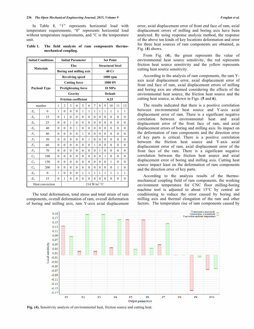
In Table 1, “1” represents horizontal load with temperature requirements, “0” represents horizontal load without temperature requirements, and °C is the temperature unit. Table 1. The field analysis of ram components thermo-
mechanical coupling.
Initial Conditions Initial Parameter Set Point
Materials Else Structural Steel
Boring and milling axis 40 Cr
Payload Type
Revolving speed 1000 rpm
Cutting force 1000 0N
Pretightening force 10 MPa
Gravity Default
Friction coefficient 0.25
number 1 2 3 4 5 6 7 8 9 10 11 12
Eh 0 1 0 0 0 1 1 1 1 1 1 1 1
Eh 15 0 1 0 0 0 0 0 0 0 0 0 0
Eh 25 0 0 1 0 0 0 0 0 0 0 0 0
Eh 40 0 0 0 1 0 0 0 0 0 0 0 0
Fh 40 0 0 0 0 1 0 0 0 0 0 0 0
Fh 50 0 0 0 0 0 1 0 0 0 0 0 0
Fh 60 0 0 0 0 0 0 1 0 0 0 0 0
Fh 70 0 0 0 0 0 0 0 1 0 0 0 0
Ch 100 0 0 0 0 0 0 0 0 1 0 0 0
Ch 150 0 0 0 0 0 0 0 0 0 1 0 0
Ch 200 0 0 0 0 0 0 0 0 0 0 1 0
Eh 0 1 0 0 0 1 1 1 1 1 1 1 1
Eh 15 0 1 0 0 0 0 0 0 0 0 0 0
Heat convection 214 W/m2·°C
The total deformation, total stress and total strain of ram components, overall deformation of ram, overall deformation of boring and milling axis, ram Y-axis axial displacement
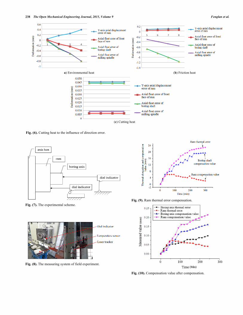
error, axial displacement error of front end face of ram, axial displacement errors of milling and boring axis have been analyzed. By using response analysis method, the response of the above ten kinds of key locations deformation and error for three heat sources of ram components are obtained, as Fig. (4) shows. From Fig. (4), the green represents the value of environmental heat source sensitivity, the red represents friction heat source sensitivity and the yellow represents cutting heat source sensitivity. According to the analysis of ram components, the ram Y-axis axial displacement error, axial displacement error of front end face of ram, axial displacement errors of milling and boring axis are obtained considering the effects of the environmental heat source, the friction heat source and the cutting heat source, as shown in Figs. (5 and 6). The results indicated that there is a positive correlation between environmental heat source and Y-axis axial displacement error of ram. There is a significant negative correlation between environmental heat and axial displacement error of the front face of ram, and axial displacement errors of boring and milling axis. Its impact on the deformation of ram components and the direction error of key parts is critical. There is a positive correlation between the friction heat source and Y-axis axial displacement error of ram, axial displacement error of the front face of the ram. There is a significant negative correlation between the friction heat source and axial displacement error of boring and milling axis. Cutting heat source impact least on the deformation of ram components and the direction error of key parts. According to the analysis results of the thermo-mechanical coupling field of ram components, the working environment temperature for CNC floor milling-boring machine tool is adjusted to about 15°C by central air conditioning to reduce the error caused by boring and milling axis and thermal elongation of the ram and other factors. The temperature rise of ram components caused by
Fig. (4). Sensitivity analysis of environmental heat, friction source and cutting heat.
Compensation of Thermal Error of Ram Components on CNC The Open Mechanical Engineering Journal, 2015, Volume 9 237
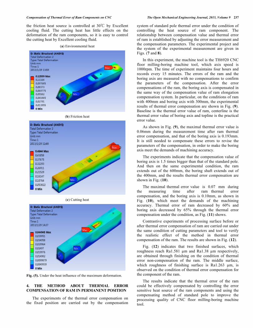
the friction heat source is controlled at 30℃ by Excellent cooling fluid. The cutting heat has little effects on the deformation of the ram components, so it is easy to control the cutting heat by Excellent cooling fluid.
(a) Environmental heat
(b) Friction heat
(c) Cutting heat
Fig. (5). Under the heat influence of the maximum deformation.
4. THE METHOD ABOUT THERMAL ERROR COMPENSATION OF RAM IN PERMANENT POSITION
The experiments of the thermal error compensation on the fixed position are carried out by the compensation
system of standard pole thermal error under the condition of controlling the heat source of ram component. The relationship between compensation value and thermal error of ram is established by adjusting the error measurement and the compensation parameters. The experimental project and the system of the experimental measurement are given in Figs. (7 and 8).
In this experiment, the machine tool is the TH6920 CNC floor milling-boring machine tool, which axis speed is 1000rpm. The time of experiment maintains four hours and records every 15 minutes. The errors of the ram and the boring axis are measured with no compensations to confirm the parameters of the compensation. After the error compensations of the ram, the boring axis is compensated in the same way of the compensation value of ram elongation compensation system. In particular, on the conditions of ram with 400mm and boring axis with 300mm, the experimental results of thermal error compensation are shown in Fig. (9). Baseline is the thermal error value of ram, centerline is the thermal error value of boring axis and topline is the practical error value. As shown in Fig. (9), the maximal thermal error value is 0.06mm during the measurement time after ram thermal error compensation, and that of the boring axis is 0.193mm. It is still needed to compensate these errors to revise the parameters of the compensation, in order to make the boring axis meet the demands of machining accuracy.
The experiments indicate that the compensation value of boring axis is 1.5 times bigger than that of the standard pole. And then on the same experimental condition, the ram extends out of the 600mm, the boring shaft extends out of the 400mm, and the results thermal error compensation are shown in Fig. (10).
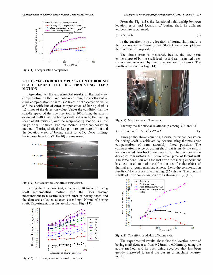
The maximal thermal error value is 0.07 mm during the measuring time after ram thermal error compensation, and the boring axis is 0.10mm, as shown in Fig. (10), which meet the demands of the machining accuracy. Thermal error of ram decreased by 60% and boring axis decreased by 65% through the thermal error compensation under the condition, as Fig. (11) shows. Contrastive experiments of processing surface before or after thermal error compensation of ram are carried out under the same condition of cutting parameters and tool to verify the realistic effect of the method in thermal error compensation of the ram. The results are shown in Fig. (12). Fig. (12) indicates that two finished surfaces, which roughness reach Ra1.581 µm and Ra1.38 µm respectively, are obtained through finishing on the condition of thermal error non-compensation of the ram. The middle surface, which roughness of finishing surface is Ra1.263 µm, is observed on the condition of thermal error compensation for the component of the ram.
The results indicate that the thermal error of the ram could be effectively compensated by controlling the error sensitive heat source of the ram components and using the compensating method of standard pole to improve the processing quality of CNC floor milling-boring machine tool.
238 The Open Mechanical Engineering Journal, 2015, Volume 9 Fenglan et al.
Fig. (7). The experimental scheme.
Fig. (8). The measuring system of field experiment.
Fig. (9). Ram thermal error compensation.
Fig. (10). Compensation value after compensation.
a) Environmental heat (b) Friction heat
(c) Cutting heat
Fig. (6). Cutting heat to the influence of direction error.
Compensation of Thermal Error of Ram Components on CNC The Open Mechanical Engineering Journal, 2015, Volume 9 239
Fig. (11). Compensation comparison.
5. THERMAL ERROR COMPENSATION OF BORING SHAFT UNDER THE RECIPROCATING FEED MOTION Depending on the experimental results of thermal error compensation on the fixed position of ram, the coefficient of error compensation of ram is 2 times of the detection value and the coefficient of error compensation of boring shaft is 1.5 times of the detection value. Under the condition that the spindle speed of the machine tool is 1000r/min, the ram is extended to 400mm, the boring shaft is driven by the feeding speed of 800mm/min, and the reciprocating motion is in the range of 0~1000mm. For the thermal error compensation method of boring shaft, the key point temperature of ram and the location error of boring shaft for CNC floor milling-boring machine tool (TH6920) are measured.
Fig. (12). Surface processing effect comparison.
During the four hour test, after every 10 times of boring shaft reciprocating motion, use the laser tracker measurement to measure location error of boring shaft, and the data are collected at each extending 100mm of boring shaft. Experimental results are shown in Fig. (13).
Fig. (13). The fitting chart of thermal error data.
From the Fig. (13), the functional relationship between location error and location of boring shaft in different temperature is obtained.
y = k ! x + b (7)
In the equation, x is the location of boring shaft and y is the location error of boring shaft. Slope k and intercept b are the function of temperature. The above error is measured, beside, the key point temperatures of boring shaft feed nut and ram principal outer surface are measured by using the temperature sensor. The results are shown as Fig. (14).
Fig. (14). Measurement of key point.
Thereby the functional relationship among k, b and ΔT. k = k ' ! "T + b ' , b = k '' ! "T + b '' (8) Through the above equation, thermal error compensation for boring shaft is achieved by accumulating thermal error compensation of ram assembly fixed position. The compensation device of boring shaft that is inside the ram is non-contacted feedback compensation. The compensation device of ram installs its interior cover plate of lateral wall. The same condition with the last error measuring experiment has been used to make verification test for the effect of thermal error compensation. Among them, the compensation results of the ram are given as Fig. (15) shows. The contrast results of error compensation are as shown in Fig. (16).
Fig. (15). The effect validation of boring axis.
The experimental results show that the location error of boring shaft decreases from 0.23mm to 0.06mm by using the above method, and its positioning accuracy that has been greatly improved to meet the design of machine require- ments.

240 The Open Mechanical Engineering Journal, 2015, Volume 9 Fenglan et al.
Fig. (16). Boring axis error contrast.
CONCLUSION
According to the distribution characteristics of ram under the force and thermal load, the responses of deformation and error on environmental heat source, friction heat source and cutting heat source have been analyzed to identify that cutting heat does not have a significant impact on the error of ram, whereas environmental heat source and friction heat does have significant influence on it. The coupled thermal field analysis result showed that the run out errors of milling spindle and boring shaft negatively correlated with the environmental heat, friction heat, the run out errors of the ram front face positively correlated with friction heat, and the run out errors of the ram front face negatively correlated with environment heat. Then the control program of thermal error compensation of ram assembly has been proposed. The experimental results of the ram thermal error show that under conditions of spindle speed 1000rpm, the ram extending 600mm and boring shaft extending 400mm, by controlling the error sensitivity of the ram assembly, the ram thermal error value decreases by 60% and the boring shaft thermal error value decreases by 65%. And the experimental results of reciprocating feed motion of boring shaft show that positioning error varies linearly with the position of boring shaft. The function of the keypoint’s temperature of ram assembly and thermal error of boring shaft is obtained by measuring the temperature of the key points, such as the feed nut of boring shaft and the outer surface of the spindle bearing Applying the compensation device for ram and boring shaft, the thermal error compensation of the boring shaft is realized through the accumulation of the thermal error compensation of the fixed position of ram. The experimental results of boring shaft thermal error compensation under the reciprocating feed motion show that positioning error of
boring shaft end face is downward from 0.23mm to 0.06mm, hence its positioning accuracy is greatly improved.
CONFLICT OF INTEREST
The authors confirm that this article content has no conflict of interest.
ACKNOWLEDGEMENTS
This work was supported by National S & T Major Project (2011ZX04002-111).
REFERENCES
[1] F. H. Wu, L.J. Qiao, and Y.L. Xiao, “Deformation compensation of ram components of super-heavy-duty CNC floor type boring and milling machine”, Chinese Journal of Aeronautics, vol. 25, pp. 269-275, 2012.
[2] X.J. Jiang, H.J. Huang, and X.Z. Wang, “Non-piece-wise error compensation for grating displacement measurement system with absolute zero mark”, Chinese Optics Letters, vol.7, pp.407-409, 2009.
[3] M. Weck, and P. Mckeown, “Reduction and compensation of thermal error in machine tools”, CIRP Annals-Manufacturing Technology, vol. 44, pp. 589-597, 1995.
[4] Lo, H. Chi, J.X. Yuan, and N. Jun, “Optimal temperature variable selection by grouping approach for thermal error modeling and compensation”, International Journal of Advanced Manufacturing Technology, vol. 39, pp. 1383-1396, 1999.
[5] C.H. Gong, J.X. Yuan, and J. Ni, “Nongeometric error identification and compensation for robotic system by inverse calibration”, International Journal of Machine Tool & Manufacture, vol. 40, pp. 2119-2137, 2000.
[6] J.D. Wang, and J.J. Guo, “Research on volumetric error compensation for nc machine tool based on laser tracker measurement”, Science China Technological Sciences, vol. 55, pp. 3000-3009, 2012.
[7] R. Ramesh, and M.A. Mannan, “Error compensation in machine tools a review: thermal errors”, International Journal of Machine Tool & Manufacture, vol. 40, pp. 1257-1284, 2000.
[8] J.X. Yuan, and J. Ni, “The real-time error compensation technique for CNC machining systems”, Mechatronics, vol. 8, pp. 359-380, 1998.
[9] S. Handel, “Analysis of a model to forecast thermal deformation of ball screw feed drive systems”, International Journal of Machine Tools & Manufacture, vol. 35, pp. 1099-1104, 1995.
[10] R. Zhu, and Z.R. Liu, “Information processing based thermal error modelling for a machine tool”, International Journal of Applied Mathematics and Statistics, vol. 48, pp. 290-297, 2013.
[11] X.S. Wang, J.G. Yang, and H. Wu, “Real time thermal error modeling and compensation of 5-axis NC grinding machine tool”, Key Engineering Materials, vol. 359, pp. 210-214, 2008.
[12] Y.F. Li, “Research on error compensation of measuring system based on closed vector chain method”, The Ninth International Conference on Electronic Measurement & Instruments, pp. 118-121, 2009.
[13] L.W. Wang, and X.D. Chen, “Motion error compensation of multi-legged walking robots”, Chinese Journal of Mechanical Engineering, vol. 25, pp. 639-645, 2012.
Received: January 8, 2015 Revised: January 15, 2015 Accepted: January 16, 2015 © Fenglan et al.; Licensee Bentham Open.
This is an open access article licensed under the terms of the Creative Commons Attribution Non-Commercial License (http://creativecommons.org/licenses/by-nc/4.0/) which permits unrestricted, non-commercial use, distribution and reproduction in any medium, provided the work is properly cited.