(2360) plant mixed asphalt pavement february 4, 2011 …
TRANSCRIPT

Page 1 of 40
(2360) PLANT MIXED ASPHALT PAVEMENT February 4, 2011
2360.1 DESCRIPTION
This work consists of constructing plant mixed asphalt pavement on a prepared subgrade.
Plant mixed asphalt pavement designed according to a gyratory mix design method for use as a pavement surface. A Mixture Designations
The Department will designate the mixture for asphalt mixtures in accordance with the following:
(1) The first two letters indicate the mixture design type: (1.1) SP = Gyratory Mixture Design.
(2) The third and fourth letters indicate the course: (2.1) WE = Wearing and shoulder wearing course, and (2.2) NW = Non-wearing Course.
(3) The fifth letter indicates the maximum aggregate size: (3.1) A = ½ in [12.5mm], SP 9.5, (3.2) B = ¾ in [19.0mm], SP 12.5, (3.3) C = 1 in [25.0mm], SP 19.0, and (3.4) D = ⅜ in [9.5mm], SP 4.75.
(4) The sixth digit indicates the Traffic Level (ESAL’s × 106) in accordance with Table 2360-1, “Traffic Levels.”
Table 2360-1 Traffic Levels
Traffic Level 20 Year Design ESALs 2 * < 1 3 ║ 1 – < 3 4 1 – < 10 5 10 – ≤ 30
NOTE: The requirements for gyratory mixtures in this specification are based on the 20 year design traffic level of the project, expressed in Equivalent Single Axle Loads (ESAL's) 1 × 10⁶ ESALs
* AADT < 2,300 ║ AADT > 2,300 to < 6,000
(5) The last two digits indicate the air void requirement:
(5.1) 40 = 4.0 percent for wear mixtures, and (5.2) 30 = 3.0 percent for non-wear and shoulder.
(6) The letter at the end of the mixture designation identifies the asphalt binder grade in accordance with Table 2360-2, “Asphalt Grades.”

Page 2 of 40
Table 2360-2 Asphalt Grades
Letter Grade A PG 52 – 34 B PG 58 – 28 C PG 58 – 34 E PG 64 – 28 F PG 64 – 34 H PG 70 – 28 L PG 64 – 22
Ex: Gyratory Mixture Designation -- SPWEB540E (Design Type, Lift, Aggr. Size, Traffic
Level, Voids, Binder) 2360.2 MATERIALS A Aggregate
Use aggregate materials in accordance with 3139.2. B Asphalt Binder Material ........................................................................................................... 3151
Table 2360-3 Asphalt Binder Selection Criteria for all Mixtures with RAP
Asphalt Binder Selection Criteria for all Mixtures with RAP
Specified PG Asphalt Binder Grade ≤ 20 % RAP > 20 % RAP*
PG XX-28 and PG 52-34 Use specified grade Use specified grade PG XX-34 Use specified grade Use blending chart*
* Use the blending chart on file with the Mn/DOT Chemical Laboratory to verify compliance with the specified binder grade when RAP is greater than 20 percent. The Department may take production samples to ensure the the asphalt binder material meets the requirements.
C Additives
The Department defines additives as material added to an asphalt mixture or material that do not have a specific pay item.
Do not incorporate additives into the mixture unless approved by the Engineer. Add anti-foaming agents to asphalt cement at the dosage rate recommended by the manufacturer. The Contractor may add mineral filler in quantities no greater than 5 percent of the total aggregate weight. The Contractor may add hydrated lime in quantities no greater than 2 percent of the total aggregate weight. Do not add a combination of mineral filler and hydrated lime that exceeds 5 percent of the total aggregate weight. Use methods for adding additives as approved by the Engineer. C.1 Mineral Filler ......................................................................................................... AASHTO M 17 C.1.a Mineral Filler – Hydrated Lime
Provide hydrated lime for asphalt mixtures with no greater than 8 percent unhydrated oxides (as received basis) and meeting the requirements of AASHTO M 216. Use a method to introduce and mix hydrated lime and aggregate as approved by the Engineer before beginning mixture production. C.2 Liquid Anti-Stripping Additive (Contractor Added)
Page 3 of 40
If adding a liquid anti-strip additive to the asphalt binder, complete blending before mixing the asphalt binder with the aggregate. Only use liquid anti-strip additives that ensure the asphalt binder meets the Performance Grade (PG) requirements in 3151. The Contractor may use asphalt binder with liquid anti-strip added at the refinery or the Contractor may add liquid anti-strip at the plant site. If using asphalt binder with liquid anti-strip added at the refinery, ensure the supplier tests the binder and additive blend to confirm compliance with the AASHTO M 320. If an anit-strip agent is added at the plant, the plant mixed asphalt producer is considered a supplier and the binder must must conform to the requirements of 3151. Do not pave until the asphalt binder and additive blend testing results meet the criteria in 2360.2.B, “Asphalt Binder Material.” C.2.a Mixture Requirements at Design
Design the mixture with the same asphalt binder supplied to the plant site using mixture option 1, “Laboratory Mixture Design” or mixture option 2, “Modified Mixture Design.”
Provide documentation with either design option and include the amount of anti-strip needed to meet the minimum tensile strength requirements. Verify that the binder with the anti-strip meets the PG binder requirements for the mixture. C.2.b Contractor Production Testing Requirements
Sample and test the asphalt binder and anti-strip blend daily. The Contractor may test the blend by viscosity, penetration, or dynamic sheer rheometer (DSR) of the blend. If the contract requires the use of a polymer modified asphalt binder in the mixture, use the DSR as the daily QC test.
Send the Engineer and Mn/DOT Chemical Laboratory Director a weekly QC report summarizing the results of the daily testing.
Perform at least one test bi-weekly per project to ensure the binder and anti-strip blend meets the requirements of AASHTO M 320. Send the test results to the Engineer and Mn/DOT Chemical Laboratory Director.
Provide asphalt binder and anti-strip blend field verification samples in accordance with 2360.2.G.7, “Production Test.” C.2.c Liquid Anti-Strip Additive Metering System
Include a liquid anti-strip flow meter and an anti-strip pump with the metering system. Connect the flow meter to the liquid anti-strip supply to measure and display only the anti-strip being fed to the asphalt binder.
Position the meter readout so that the inspector can easily read it.
Provide means to compare the flow meter readout with the calculated output of the anti-strip pump.
Provide a system that displays the accumulated anti-strip quantity being delivered to the mixer unit in gallons [liters] to the nearest gallon [liter] or in units of tons [metric tons] to the nearest 0.001 ton [0.001 tonne].
Calibrate and adjust the system to maintain an accuracy of ± 1 percent.
Calibrate each plant set-up before producing the mixture.
“Stick” the anti-strip tank at the end of the day’s production to verify anti-strip usage quantities. The Engineer may require “sticking” on a daily basis.

Page 4 of 40
Ensure the system has a spigot for sampling the binder and anti-strip after blending.
Use alternative blending and metering systems only when pre-approved by the Engineer. C.3 Coating and Anti Stripping Additive ...................................................................................... 3161 D Bituminous Tack Coat .............................................................................................................. 2357 E Mixture Design E.1 Submittal Location
Submit documentation and sample aggregate materials for review to the District Materials Laboratory. E.2 Aggregate Quality
Provide aggregate in accordance with 3139.2. E.3 Restrictions
Do not add aggregates and materials not included n the original mixture submission unless otherwise approved by the Engineer. E.4 Responsibility
Design a gyratory mixture that meets the requirements of this specification in accordance with the following:
(1) Most current AASHTO T 312, Mn/DOT modified, (2) The Asphalt Institute’s Superpave Mix Design Manual SP-2 (Use a 2 h short term aging
period for volumetric), and (3) The Laboratory Manual.
E.5 Type of Mixture Design Submittal E.5.a Option 1 — Laboratory Mixture Design E.5.a(1) Aggregate
Submit the aggregate samples for option 1, at least 15 working days before beginning production samples for quality testing. At least 30 calendar days before beginning asphalt production, submit samples of aggregates that require the magnesium sulfate soundness test to the District Materials Laboratory. Test the samples for quality of each source, class, type, and size of virgin and non-asphaltic salvage aggregate source used in the mix design. Retain a companion sample of equal size until the Department issues a Mixture Design Report. Provide 24 h notice of intent to sample aggregates to the Engineer. Provide samples in accordance with the following:
Table 2360-4 Aggregate Sample Size
Classification Sieve Weight Virgin Retained on No. 4 [4.75 mm] 80 lb [35 kg] Virgin Passing No. 4 [4.75 mm] 35 lb [15 kg] Recycled asphalt pavement (RAP) — 80 lb [35 kg]
Recycled asphalt shingles (RAS) — 10 lb [5 kg] sample of
representative RAS material
Page 5 of 40
E.5.a(2) Mixture Sample
At least 7 working days before the start of asphalt production, submit the proposed Job Mix Formula (JMF) in writing and signed by a Level II Quality Management mix designer for each combination of aggregates to be used in the mixture. Include test data to demonstrate conformance to mixture properties as specified in Table 2360-7, “Mixture Requirements,” and 3139.2, “Bituminous Aggregates.” Use forms approved by the Department for the submission.
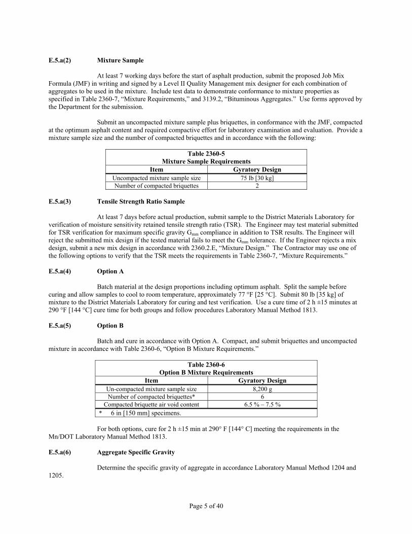
Submit an uncompacted mixture sample plus briquettes, in conformance with the JMF, compacted at the optimum asphalt content and required compactive effort for laboratory examination and evaluation. Provide a mixture sample size and the number of compacted briquettes and in accordance with the following:
Table 2360-5 Mixture Sample Requirements
Item Gyratory Design Uncompacted mixture sample size 75 lb [30 kg] Number of compacted briquettes 2
E.5.a(3) Tensile Strength Ratio Sample
At least 7 days before actual production, submit sample to the District Materials Laboratory for verification of moisture sensitivity retained tensile strength ratio (TSR). The Engineer may test material submitted for TSR verification for maximum specific gravity Gmm compliance in addition to TSR results. The Engineer will reject the submitted mix design if the tested material fails to meet the Gmm tolerance. If the Engineer rejects a mix design, submit a new mix design in accordance with 2360.2.E, “Mixture Design.” The Contractor may use one of the following options to verify that the TSR meets the requirements in Table 2360-7, “Mixture Requirements.” E.5.a(4) Option A
Batch material at the design proportions including optimum asphalt. Split the sample before curing and allow samples to cool to room temperature, approximately 77 °F [25 °C]. Submit 80 lb [35 kg] of mixture to the District Materials Laboratory for curing and test verification. Use a cure time of 2 h ±15 minutes at 290 °F [144 °C] cure time for both groups and follow procedures Laboratory Manual Method 1813. E.5.a(5) Option B
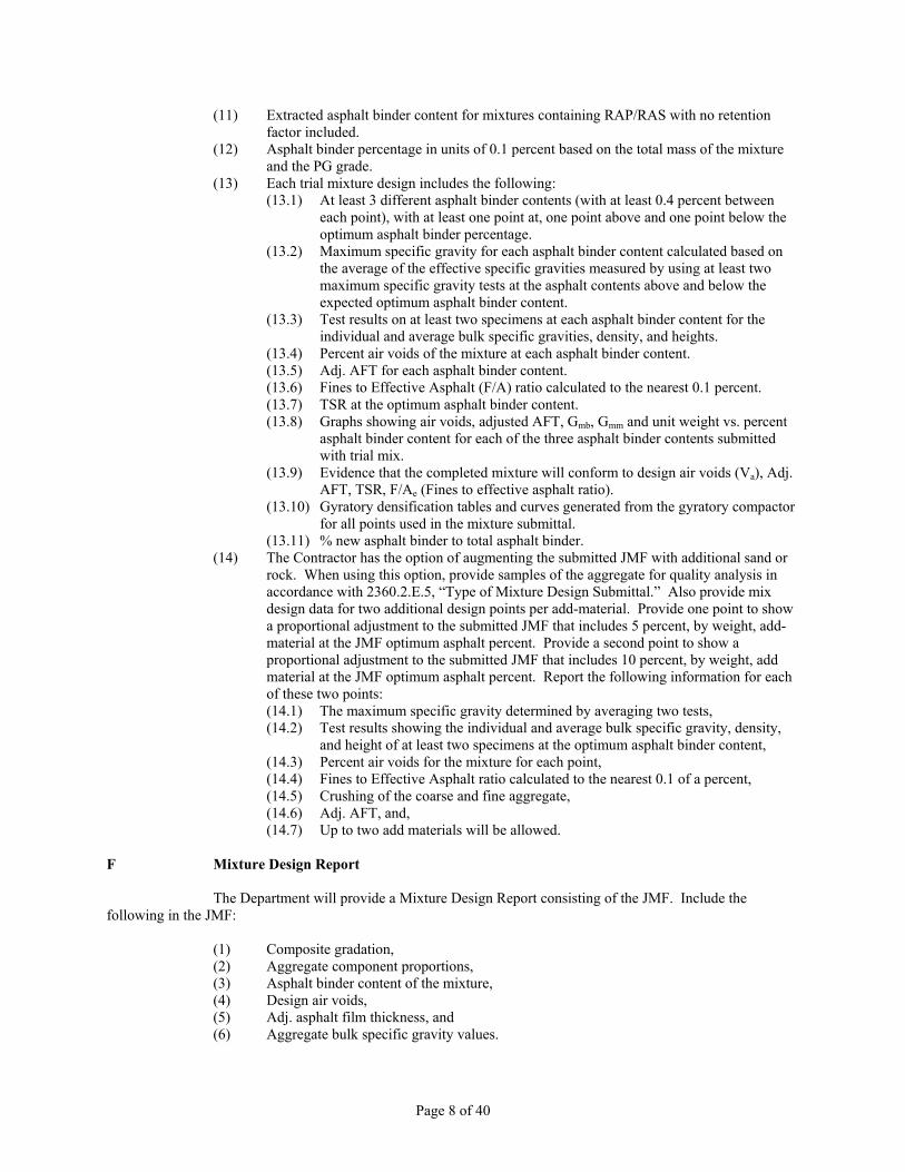
Batch and cure in accordance with Option A. Compact, and submit briquettes and uncompacted mixture in accordance with Table 2360-6, “Option B Mixture Requirements.”
Table 2360-6 Option B Mixture Requirements
Item Gyratory Design Un-compacted mixture sample size 8,200 g Number of compacted briquettes* 6
Compacted briquette air void content 6.5 % – 7.5 % * 6 in [150 mm] specimens.
For both options, cure for 2 h ±15 min at 290° F [144° C] meeting the requirements in the
Mn/DOT Laboratory Manual Method 1813. E.5.a(6) Aggregate Specific Gravity
Determine the specific gravity of aggregate in accordance Laboratory Manual Method 1204 and 1205.

Page 6 of 40
E.5.b Option 2 — Modified Mixture Design
The Contractor may use the modified mixture design if testing shows that the aggregates meet the requirements of 3139.2 in the current construction season and if the Level II mix designer submitting the mixture design has at least 2 years experience in mixture design. The Department will not require mixture submittal. E.5.b(1) Mixture Aggregate Requirements
Size, grade, and combine the aggregate fractions in proportions that are in accordance with 3139.2. E.5.b(2) JMF Submittal
At least 2 working days before beginning asphalt production, submit a proposed JMF in writing to the District Materials Laboratory signed by a Level II Quality Management mix designer for each combination of aggregates. For each JMF submitted, include documentation in accordance with 2360.2.E.5.a, “Option1 – Laboratory Mixture Design,” to demonstrate conformance to mixture properties as specified in Table 2360-7, “Mixture Requirements,” and Table 3139-3, “Mixture Aggregate Requirements.” Submit the JMF on forms approved by the Department. E.5.b(3) Initial Production Test Verification
The Department will take a mix verification sample within the first four samples at the start of production of each mix type. A Field tensile strength ratio (TSR) sample will be taken and tested within the first 5,000 tons [4500 tonnes] of the start of production if required by the Engineer. E.6 Mixture Requirements
The Department will base mixture evaluation on the trial mix tests and in accordance with Table 2360-7, “Mixture Requirements.”
Table 2360-7 Mixture Requirements
Traffic Level 2 3 4 5 20 year design ESALs < 1 million 1 – 3 million 3 – 10 million 10 – 30 million Gyratory mixture requirements:
Gyrations for Ndesign 40 60 90 100 % Air voids at Ndesign, wear 4.0 4.0 4.0 4.0 % Air voids at Ndesign, Non-wear and all shoulder 3.0 3.0 3.0 3.0 Adjusted Asphalt Film Thickness, minimum µ 8.5 8.5 8.5 8.5 Ratio of Added New Asphalt Binder to Total Asphalt Binder,(1), min% 70 70 70 70 TSR*, minimum % 75║ 75║ 80† 80† Fines/effective asphalt 0.6 – 1.2 0.6 – 1.2 0.6 – 1.2 0.6 – 1.2
* Use 6 in [150 mm] specimens in accordance with 2360.2.I, “Field Tensile Strength Ratio (TSR).”
║ Mn/DOT minimum = 65 † Mn/DOT minimum = 70 1 The ratio of added new asphalt binder to total asphalt binder needs to be 70% or greater ((added binder/total binder) x 100 ≥ 70) in both mixtures that contain RAP and in mixtures that include shingles as part of the allowable RAP percentage.

Page 7 of 40
E.7 Coarse/Fine Mixture Determination
Base the determination of coarse and fine graded mixtures on the percentage of material passing the No. 8 [2.36 mm] sieve in accordance with Table 2360-8, “Coarse/Fine Mixture Determination.”
Table 2360-8 Coarse/Fine Mixture Determination
Gradation Fine Mixture,
% passing No. 8 [2.36 mm] Coarse Mixture,
% passing No. 8 [2.36 mm] A > 47 ≤ 47 B > 39 ≤ 39 C > 35 ≤ 35 D — —
E.8 Adjusted Asphalt Film Thickness (Adj. AFT) ...... Mn/DOT Laboratory Manual Method 1854
Ensure the adjusted asphalt film thickness (Adj. AFT) of the mixture at design and during production meets the requirements of Table 2360-7,”Mixture Requirements.” Base the Adj. AFT on the calculated aggregate surface area (SA) and the effective asphalt binder content. E.9 Documentation
Include the following documentation and test results with each JMF submitted for review:
(1) Names of the individuals responsible for the QC of the mixture during production, (2) Low project number of the contract on which the mixture will be used, (3) Traffic level and number of gyrations, (4) The following temperature ranges as supplied by the asphalt binder supplier:
(4.1) Laboratory mixing and compaction, (4.2) Plant discharge, and (4.3) Field compaction.
(5) The percentage in units of 1 percent (except the No. 200 sieve [0.075 mm] in units of 0.1 percent) of aggregate passing each of the specified sieves (including the No. 16, No. 30, No. 50, and No. 100) for each aggregate to be incorporated into the mixture. Derive the gradation of the aggregate from the RAP after extracting the residual asphalt.
(6) Source descriptions of the following: (6.1) Location of material, (6.2) Description of materials, (6.3) Aggregate pit or quarry number, and (6.4) Proportion amount of each material in the mixture in percent of total aggregate.
(7) Composite gradation based on (5) and (6) above. Include virgin composite gradation based on (6) and (7) above for mixtures containing RAP/RAS.
(8) Bulk and apparent specific gravities and water absorption (by % weight of dry aggregate). Both coarse and fine aggregate, for each product used in the mixture (including RAP/RAS). Use Mn/DOT Laboratory Manual Method 1204 and 1205. The tolerance allowed between the Contractor's and the Department's specific gravities are Gsb (individual) = 0.040 [+4 and -4] and Gsb (combined) = 0.020.
(9) FHWA 0.45 power chart represented by the composite gradation plotted on Federal Form PR-1115
(10) Test results from the composite aggregate blend at the proposed JMF proportions showing compliance with Table 3139-3: (10.1) Coarse Aggregate Angularity, (10.2) Fine Aggregate Angularity, and (10.3) Flat and Elongated
Page 8 of 40
(11) Extracted asphalt binder content for mixtures containing RAP/RAS with no retention factor included.
(12) Asphalt binder percentage in units of 0.1 percent based on the total mass of the mixture and the PG grade.
(13) Each trial mixture design includes the following: (13.1) At least 3 different asphalt binder contents (with at least 0.4 percent between
each point), with at least one point at, one point above and one point below the optimum asphalt binder percentage.
(13.2) Maximum specific gravity for each asphalt binder content calculated based on the average of the effective specific gravities measured by using at least two maximum specific gravity tests at the asphalt contents above and below the expected optimum asphalt binder content.
(13.3) Test results on at least two specimens at each asphalt binder content for the individual and average bulk specific gravities, density, and heights.
(13.4) Percent air voids of the mixture at each asphalt binder content. (13.5) Adj. AFT for each asphalt binder content. (13.6) Fines to Effective Asphalt (F/A) ratio calculated to the nearest 0.1 percent. (13.7) TSR at the optimum asphalt binder content. (13.8) Graphs showing air voids, adjusted AFT, Gmb, Gmm and unit weight vs. percent
asphalt binder content for each of the three asphalt binder contents submitted with trial mix.
(13.9) Evidence that the completed mixture will conform to design air voids (Va), Adj. AFT, TSR, F/Ae (Fines to effective asphalt ratio).
(13.10) Gyratory densification tables and curves generated from the gyratory compactor for all points used in the mixture submittal.
(13.11) % new asphalt binder to total asphalt binder. (14) The Contractor has the option of augmenting the submitted JMF with additional sand or
rock. When using this option, provide samples of the aggregate for quality analysis in accordance with 2360.2.E.5, “Type of Mixture Design Submittal.” Also provide mix design data for two additional design points per add-material. Provide one point to show a proportional adjustment to the submitted JMF that includes 5 percent, by weight, add-material at the JMF optimum asphalt percent. Provide a second point to show a proportional adjustment to the submitted JMF that includes 10 percent, by weight, add material at the JMF optimum asphalt percent. Report the following information for each of these two points: (14.1) The maximum specific gravity determined by averaging two tests, (14.2) Test results showing the individual and average bulk specific gravity, density,
and height of at least two specimens at the optimum asphalt binder content, (14.3) Percent air voids for the mixture for each point, (14.4) Fines to Effective Asphalt ratio calculated to the nearest 0.1 of a percent, (14.5) Crushing of the coarse and fine aggregate, (14.6) Adj. AFT, and, (14.7) Up to two add materials will be allowed.
F Mixture Design Report
The Department will provide a Mixture Design Report consisting of the JMF. Include the following in the JMF:
(1) Composite gradation, (2) Aggregate component proportions, (3) Asphalt binder content of the mixture, (4) Design air voids, (5) Adj. asphalt film thickness, and (6) Aggregate bulk specific gravity values.
Page 9 of 40
Show the JMF limits for gradation control sieves in accordance with aggregate gradation broadbands shown in Table 3139-2, percent asphalt binder content, air voids, and Adj. AFT. If the Department issues a Mixture Design Report, this report only confirms that the Department reviewed the mixture and that it meets volumetric properties. The Department makes no expressed or implied guaranty or warranty regarding placement and compaction of the mixture.
Provide materials meeting the requirements of the aggregate and mixture design before issuing a Mixture Design Report. The Department will review two trial mix designs per mix type designated in the plan per contract at no cost to the Contractor. The Department will verify additional mix designs at a cost of $2,000 per design.
Provide a Department - reviewed Mixture Design Report for all paving except for small quantities of material as described in 2360.3.G, “Small Quantity Paving.”
For city, county, and other agency projects, provide the District Materials Laboratory a complete project proposal, including addenda, supplemental agreements, change orders, and plans sheets, including typical sections, affecting the mix design before the Department begins the verification process. G Mixture Quality Management G.1 Quality Control (QC)
Provide and maintain a QC program for plant mix asphalt production, including mix design, process control inspection, sampling and testing, and adjustments in the process related to the production of an asphalt pavement. G.1.a Certification
Provide the following to obtain certification:
(1) Completed and submitted request form application for plant inspection. (2) Site map showing stockpile locations. (3) Signed asphalt plant inspection report showing the plant and testing facility passed as
documented by Asphalt Plant Inspection Report (TP 02142-02, TP 02143-02). The inspection report must also include documentation showing plant and laboratory equipment has been calibrated and is being maintained to the tolerance shown in the Bituminous Manual and sections 1200, 1800, and 2000 of the Mn/DOT Laboratory Manual.
(4) A Department-signed Mixture Design Report (MDR) before mixture production. G.1.b Maintaining Certification
Maintain plant certification by documenting the production and testing of the certified plant asphalt mixtures. Sample and test asphalt mixtures in accordance with this section and meeting the requirements of the Schedule of Materials Control. G.1.b(1) Annual Certification
Perform annual certification after winter suspension. G.1.b(2) Sampling Rate
Sample at the rate in accordance with 2360.2.G.6 and the requirements of the Schedule of Materials Control. G.1.b(3) Plant Moved

Page 10 of 40
Recertify the plant if the plant moves to a new or previously occupied location.
G.1.c. Plant Certification Revocation
The Engineer may revoke certification for any of the following reasons:
(1) If the mix does not meet the requirements of 2360.2.E.6 and 3139.2, (2) If there is a failure to meet the testing rates, or (3) If it is determined records were falsified.
If the Engineer revokes plant certification, the Department may revoke the Technical Certification
of the individual or individuals involved. The Department will maintain a list of companies with revoked certifications. G.2 Quality Assurance (QA)
The Engineer will perform Quality Assurance (QA) on a sample that is a companion to the Contractor’s QC sample to accept the work. The Engineer will perform the following:
(1) Conduct QA and verification sampling and testing, (2) Observe the QC sampling and tests, (3) Monitor the required QC summary sheets and control charts, (4) Verify calibration of QC laboratory testing equipment, (5) Communicate Department test results to the Contractor’s personnel on a daily basis, and (6) Ensure Independent Assurance (IA) sampling and testing requirements are met.
The Engineer will periodically witness the sampling and testing being performed by the
Contractor. If the Engineer observes that the Contractor is not performing sampling and quality control tests in accordance with the applicable test procedures, the Engineer may stop production until the Contractor takes corrective action. The Engineer will notify the Contractor of observed deficiencies promptly, both verbally and in writing.
The Engineer may obtain additional samples, at any time and location during production, to determine quality levels in accordance with 2360.2.G.3, “Verification Sample.”
The Department will post a chart with the names and telephone numbers for the personnel responsible for QA.
The Engineer will calibrate and correlate laboratory testing equipment in accordance with the Bituminous Manual and Laboratory Manual.
Page 11 of 40
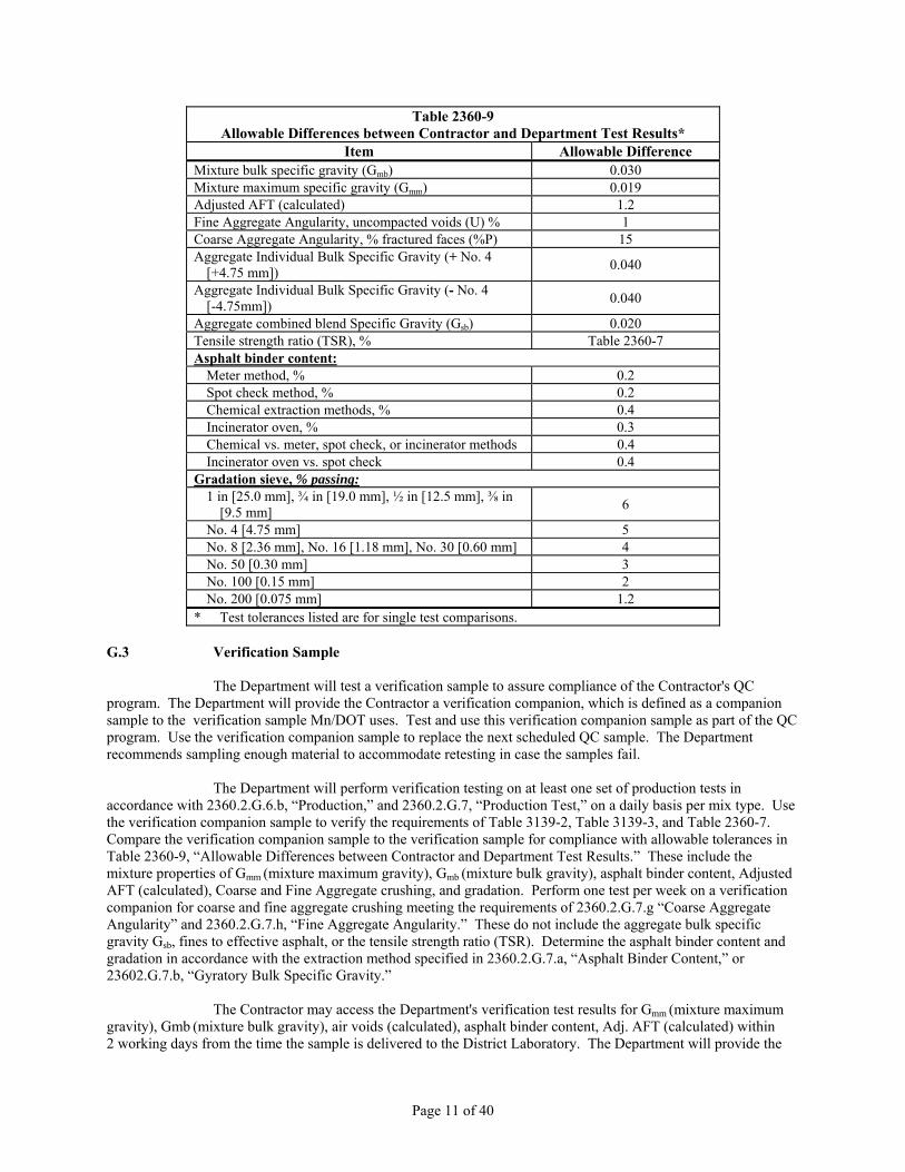
Table 2360-9 Allowable Differences between Contractor and Department Test Results*
Item Allowable Difference Mixture bulk specific gravity (Gmb) 0.030 Mixture maximum specific gravity (Gmm) 0.019 Adjusted AFT (calculated) 1.2 Fine Aggregate Angularity, uncompacted voids (U) % 1 Coarse Aggregate Angularity, % fractured faces (%P) 15 Aggregate Individual Bulk Specific Gravity (+ No. 4
[+4.75 mm]) 0.040
Aggregate Individual Bulk Specific Gravity (- No. 4 [-4.75mm]) 0.040
Aggregate combined blend Specific Gravity (Gsb) 0.020 Tensile strength ratio (TSR), % Table 2360-7 Asphalt binder content:
Meter method, % 0.2 Spot check method, % 0.2 Chemical extraction methods, % 0.4 Incinerator oven, % 0.3 Chemical vs. meter, spot check, or incinerator methods 0.4 Incinerator oven vs. spot check 0.4
Gradation sieve, % passing: 1 in [25.0 mm], ¾ in [19.0 mm], ½ in [12.5 mm], ⅜ in
[9.5 mm] 6
No. 4 [4.75 mm] 5 No. 8 [2.36 mm], No. 16 [1.18 mm], No. 30 [0.60 mm] 4 No. 50 [0.30 mm] 3 No. 100 [0.15 mm] 2 No. 200 [0.075 mm] 1.2
* Test tolerances listed are for single test comparisons. G.3 Verification Sample
The Department will test a verification sample to assure compliance of the Contractor's QC program. The Department will provide the Contractor a verification companion, which is defined as a companion sample to the verification sample Mn/DOT uses. Test and use this verification companion sample as part of the QC program. Use the verification companion sample to replace the next scheduled QC sample. The Department recommends sampling enough material to accommodate retesting in case the samples fail.
The Department will perform verification testing on at least one set of production tests in accordance with 2360.2.G.6.b, “Production,” and 2360.2.G.7, “Production Test,” on a daily basis per mix type. Use the verification companion sample to verify the requirements of Table 3139-2, Table 3139-3, and Table 2360-7. Compare the verification companion sample to the verification sample for compliance with allowable tolerances in Table 2360-9, “Allowable Differences between Contractor and Department Test Results.” These include the mixture properties of Gmm (mixture maximum gravity), Gmb (mixture bulk gravity), asphalt binder content, Adjusted AFT (calculated), Coarse and Fine Aggregate crushing, and gradation. Perform one test per week on a verification companion for coarse and fine aggregate crushing meeting the requirements of 2360.2.G.7.g “Coarse Aggregate Angularity” and 2360.2.G.7.h, “Fine Aggregate Angularity.” These do not include the aggregate bulk specific gravity Gsb, fines to effective asphalt, or the tensile strength ratio (TSR). Determine the asphalt binder content and gradation in accordance with the extraction method specified in 2360.2.G.7.a, “Asphalt Binder Content,” or 23602.G.7.b, “Gyratory Bulk Specific Gravity.”
The Contractor may access the Department's verification test results for Gmm (mixture maximum gravity), Gmb (mixture bulk gravity), air voids (calculated), asphalt binder content, Adj. AFT (calculated) within 2 working days from the time the sample is delivered to the District Laboratory. The Department will provide the
Page 12 of 40
gradation and crushing results to the Contractor within three working days. The Department will include the verification test results on the test summary sheet. The Department will compare the results with the Contractor’s verification companion for the allowable tolerances in Table 2360-9, “Allowable Differences between Contractor and Department Test Results.” The Department will consider the verification process complete if the Contractor’s verification companion meets the tolerances in Table 2360-9.
If the tolerances between the Contractor’s verification companion and the Department’s verification sample do not meet the requirements of Table 2360-9, the Department will retest the material. If the retests fail to meet tolerances, the Department will substitute the Department's verification test results for the Contractor’s results in the QC program and use those results for acceptance. The Department will only substitute the out-of-tolerance parameters and will recalculate volumetric properties if applicable.
If the Adj. AFT calculation does not meet the tolerance, equalize the Department Adj.AFT result by increasing the original Department value by 0.5 microns. Use the increased Department Adj. AFT for the Individual Adjusted AFT result and to calculate the Moving Average Adj. AFT results. The increased Department Adj. AFT will form the basis for acceptance.
If the verification sample retests do not meet tolerances, the Department will investigate the cause of the difference that will include a review of testing equipment, procedures, worksheets, gyratory specimen height sheets, and personnel to determine the source of the problem. The Engineer may require both the Department and Contractor to perform at least one hot-cold comparison of mixture properties.
To perform a hot-cold comparison, split the sample into three representative portions. The Engineer will observe the Contractor testing. Immediately compact one part while still hot. Apply additional heating to raise the temperature of the sample to compaction temperature if necessary. Allow the second and third part to cool to air temperature. Retain the second part and transport the third part to the District Materials Laboratory. On the same day and at the same time as the District Materials Laboratory, heat samples to compaction temperature and compact. Develop a calibration factor to compare the specific gravity of the hot compacted samples to reheated compacted samples. Use at least two gyratory specimens for each test. The Engineer or the Contractor may request that this test be repeated. Reheat mix samples to 160° F [70° C] to allow splitting of the sample into representative fractions for the various tests. Do not overheat the mixture portions used for testing maximum specific gravity test.
The Department will test the previously collected QA samples until they meet the tolerances or until the Department has tested all of the remaining samples. After testing the samples, the Department will test QA samples subsequent to the verification sample until tolerances are met. The Department will base acceptance on QC data. The Department will base acceptance on QC data with substitution of Department test results for those parameters out of tolerance. Cease mixture production and placement if reestablished test results do not meet tolerances within 48 h. Resume production and placement only after meeting the tolerances. The process for dispute resolution is available on the Bituminous Office website.
If the Engineer analyzes the data using methods for determination of bias on file in the Bituminous Office and finds a bias in the test results, the Engineer will specify which results to use. If through analysis of data, it is determined that there is a bias in the test results, the Engineer will determine which results are appropriate and will govern. G.4 Contractor Quality Control G.4.a Personnel
Submit an organizational chart listing the names and phone numbers of individuals and alternates responsible for the following:
(1) Mix design, (2) Process control administration, and (3) Inspection.

Page 13 of 40
Provide QC technicians certified as a Level I Bituminous Quality Management (QM) Tester
meeting the requirements of the Mn/DOT Technical Certification Program for QC testing and Level II Bituminous QM Mix Designer to make process adjustments. Provide at least one person per paving operation certified as a Level II Bituminous Street Inspector.
Provide a laboratory with equipment and supplies for Contractor quality control testing and maintain with the following:
(1) Up-to-date equipment calibrations and a copy of the calibration records with each piece of equipment,
(2) Telephone, (3) Fax and copy machine; however, the Engineer may waive the requirement to have a fax
machine if internet and email are available, (4) Internet and Email, (5) Computer, (6) Printer, and (7) Microsoft Excel, version 2007 or newer
Laboratory equipment need to meet the requirements listed in Section 400 of the Bituminous
Manual, Laboratory Manual, and these specifications, including having extraction capabilities. Before beginning production, the laboratory equipment needs to be calibrated and operational.
Calibrate and correlate all testing equipment in accordance with the Bituminous Manual and Laboratory Manual. Keep records of calibration for each piece of testing equipment in the same facility as the equipment. G.4.b Sampling and Testing
Take QC samples at random locations, quartered from a larger sample of mixture, from behind the paver and in accordance with the Schedule of Materials Control. The Engineer may approve alternate sampling locations. When the Engineer approves of an alternate sampling location and used by the Contractor, the daily verification sample must still be taken from behind the paver. The procedure for truck box sampling, an alternate sampling location, is on file in the Bituminous Office. Store compacted mixture specimens and loose mixture companion samples for 10 calendar days. Label these split companion samples with companion numbers. Determine random numbers and locations using the Bituminous Manual, Section 5-693.7 Table A or ASTM D 3665, Section 5. G.5 Production Test Requirements
Determine the planned tonnage [metric tons] for each mixture planned for production during the production day. Divide the planned production by 1,000 and round to the next highest whole number. The result is the number of production tests required for the mixture. Table 2360-11, “Production Testing Rates” shows the required production tests.
Split the planned production into even increments and select sample locations as described above. If actual tonnage is greater than the planned tonnage, repeat the calculation above and provide additional tests if the calculation results in a higher number of production tests. During production, the Department will not require mixture volumetric property tests if mix production is no greater than 300 ton [270 tonne]. Provide production tests if the accumulative weight on successive days is greater than 300 ton [270 tonne].
If there is a choice of more than one Mn/DOT approved test procedure, select one method at the beginning of the project with the approval of the Engineer and use that method for the entire project. The Contractor and Engineer may agree to change test procedures during the construction of the project. G.5a Establishing an Ignition Oven Correction Factor ......... Mn/DOT Lab. Manual 1852 Appendix

Page 14 of 40
On the first day of production, for each mixture type, both the Contractor and the Agency will
establish an ignition oven correction factor from the produced mixture. Re-establish correction factors when:
There are aggregate or RAP substitutions
There are 3 or more tolerance failures on the extracted asphalt content between the Agency and the Contractor as defined by Table 2360-9, “Allowable Differences between Contractor and Department Test Results”. G.6 Production Testing Rates G.6.a Start –Up
At the start of production, for the first 2,000 ton [1,800 tonne] of each mix type, perform testing at the following frequencies:
Table 2360-10 Production Start-Up Testing Rates
Production Test Testing Rates
Laboratory Manual Method Section
Bulk Specific Gravity
1 test per 500 ton [450 tonne] 1806 2360.2.G.7.b
Maximum Specific Gravity
1 test per 500 ton [450 tonne] 1807 2360.2.G.7.c
Air Voids (calculated)
1 test per 500 ton [450 tonne] 1808 2360.2.G.7.d
Asphalt Content
1 test per 500 ton [450 tonne] 1853 2360.2.G.7.a
Add AC/Total AC Ratio (calculated)
1 test per 1000 ton [900 tonne] 1853 2360.2.G.7.a
Adj. AFT (Calculated)
1 test per 500 ton [450 tonne] 1854 2360.2.E.6.b
Gradation 1 test per 500 ton [450 tonne] 1203 2360.2.G.7.f
Coarse Aggregate Angularity
1 test per 1,000 tons [900
tonne] 1214 2360.2.G.7.g
Fine Aggregate Angularity (FAA)
1 test per 1,000 ton [900 tonne] 1213 2360.2.G.7.h
Fines to Effective Asphalt Ratio (calculated)
1 test per 500 ton [450 tonne] 1203 & 1853 2360.2.G.7.f &
2360.2.G.7.a
G.6.b Production
After producing the first 2,000 ton [1,800 tonne] of each mix type test at the following frequencies:

Page 15 of 40
Table 2360-11 Production Testing Rates
Production Test Sampling and Testing Rates Test Reference Section
Bulk Specific Gravity
Divide the planned production by 1,000. Round the number to the next higher whole number
Laboratory Manual 1806 2360.2.G.7.b
Maximum Specific Gravity
Divide the planned production by 1,000. Round the number to the next higher whole number.
Laboratory Manual 1807 2360.2.G.7.c
Air Voids (calculated)
Divide the planned production by 1,000. Round the number to the next higher whole number
Laboratory Manual 1808 2360.2.G.7.d
Asphalt Content Divide the planned production
by 1,000. Round the number to the next higher whole number
Laboratory Manual 1853 2360.2.G.7.a
Add AC/Total AC Ratio (calculated)
Divide the planned production by 2000. Round the number to the next higher whole number
Laboratory Manual 1853 2360.2.G.7.a
Adj. AFT (Calculated)
Divide the planned production by 1,000. Round the number to the next higher whole number
Laboratory Manual 1854 2360.2.E.7.e
Gradation 1 gradation per 1,000 tons
[900 tonne], or portion thereof (at least one per day)
Laboratory Manual 1203 2360.2.G.7.f
Coarse Aggregate Angularity
2 tests per day for at least 2 days, then 1 per day if CAA is
met. If CAA >8% of requirement, 1 sample per day
but test 1 per week.
Laboratory Manual 1214 2360.2.G.7.g
Fine Aggregate Angularity (FAA)
2 tests per day for at least 2 days, then 1 per day if FAA is
met. If FAA >5% of requirement, 1 sample per day
but test 1 per week.
Laboratory Manual 1213 2360.2.G.7.h
Fines to Effective Asphalt Ratio (calculated)
Divide the planned production by 1,000. Round the number to the next higher whole number
Laboratory Manual 1203 & 1853
2360.2.G.7.f &
2360.2.G.7.a
TSR As directed by the Engineer Laboratory Manual 1213 2360.G.7.i
Aggregate Specific Gravity
As directed by the Engineer Laboratory
Manual 1204, 1205, and 1815
2360.G.7.j
Mixture Moisture Content
Daily unless otherwise required by the Engineer
Laboratory Manual 1805 2360.G.7.k
Asphalt Binder Sample first load (each grade), then 1 per 250,000 gal sample
size 1 qt [1,000,000 L]
Mn/DOT Bituminous
Manual 5-693.920
2360.G.7.l
G.7 Production Tests G.7.a Asphalt Binder Content
Page 16 of 40
Use spot check for determination of asphalt binder content in virgin mixtures only. See the requirements of the Bituminous Manual.
Spotchecks are required only when the Engineer has waived the requirements of 2360.2G8 relating to furnishing a computerized printout of the plant blending control system. A minimum of 1 spotcheck per day per mixture blend is required to determine the new added asphalt binder.
Use an incinerator oven meeting the requirements of the Laboratory Manual Method 1853. Do not use the incinerator oven if the percentage of Class B material is greater than 50 percent within the composite blend, unless the Contractor determines a correction factor approved by the Engineer.
Perform chemical extraction meeting the requirements of Laboratory Manual Method 1851 or 1852.
Use the meter method for determination of asphalt binder content in virgin mixtures only. See the requirements of the Bituminous Manual. G.7.b Gyratory Bulk Specific Gravity, Gmb Use two specimens to determine gyratory bulk specific gravity meeting the requirements of Laboratory Manual Method 1806. Set Gyratory to an internal angle of 1.16° ± 0.02° according to AASHTO TP 71. G.7.c Maximum Specific Gravity, Gmm
Determine maximum specific gravity meeting the requirements of Laboratory Manual Method 1807. G.7.d Air Voids – Individual and Isolated (Calculation)
Calculate the individual and isolated air voids meeting the requirements of Laboratory Manual Method 1808. Use the maximum mixture specific gravity and corresponding bulk specific gravity from a single test to calculate the isolated air voids. Use the maximum specific gravity moving average and the bulk specific gravity from a single test to calculate the individual air voids.
Compact gyratory design to Ndesign in accordance with Table 2360-7, “Mixture Requirements” for the specified traffic level. G.7.e Adjusted Asphalt Film Thickness (AFT) (Calculation)
Calculate the Adj. AFT meeting the requirements of the Laboratory Manual Method 1854. G.7.f Gradation – Blended Aggregate
Determine the gradation of blended aggregate sample, from an extracted bituminous mixture, meeting the requirements of Laboratory Manual Method 1203. G.7.g Coarse Aggregate Angularity
Test the Coarse Aggregate Angularity (CAA) meeting the requirements of Laboratory Manual Method 1214 to determine the CAA on composite blend from aggregates used in production of hot mix asphalt. Ensure CAA test results meet the requirements in accordance with Table 3139-3.
The Contractor may test mixtures containing virgin aggregates from composite belt samples. Test mixtures containing RAP from extracted aggregates taken from standard production samples. Test the percentage of fractured faces of the composite aggregate blend less than 100 percent twice a day for each mixture blend for at least

Page 17 of 40
two days, then one test per day if the test samples meet the CAA requirements. If the CAA crushing test results are greater than 8 percent of the requirements, take one sample per day and perform one test per week.
Report CAA results on the test summary sheet. The Department may reduce payment in accordance with Table 2360-15, “Reduced Payment Schedule for Individual Test Results,” for mixture placed and represented by results below the minimum requirement in accordance with Table 3139-3. The Department will calculate tonnage subjected to reduced payment as the tons placed from the sample point of the failing test to the sampling point where the test result meets the specifications. G.7.h Fine Aggregate Angularity
Use Laboratory Manual Method 1813 to test the composite blend from aggregates used in production of asphalt mixtures for Fine Aggregate Angularity (FAA) meeting the requirements of Table 3139-3. The Contractor may test mixtures that contain virgin aggregates from composite belt samples. Test mixtures that contain RAP from extracted aggregates taken from standard production samples. Perform two tests per day for each mixture blend for at least two days to test the percentage of uncompacted voids from the composite aggregate blend, then one test per day if the samples meet FAA requirements. If FAA test results are greater than 5 percent of the requirement, take one sample per day and one test per week.
Report FAA results on the test summary sheet. The Department may reduce payment in accordance with Table 2360-16, “Reduced Payment Schedule for Individual Test Results,” for mixture placed and represented by results below the minimums in accordance with Table 3139-3. The Department will calculate tonnage subjected to reduced payment as the tons placed from the sample point of the failing test to the sampling point where the test result meets the specifications. G.7.i Field Tensile Strength Ratio (TSR) ........................................ Laboratory Manual Method 1813
If the Engineer requires sampling and testing of the mixture to verify tensile strength ratio (TSR), both the Contractor and the Department will be required to test these samples within 72 h after sampling. The Contractor shall obtain a sample weighing at least 110 lb [50 kg] and split the sample in half to provide a sample for the Department and the Contractor. Label the Department companion of this split with the following information:
(1) Date, (2) Time, (3) Project number, and (4) Cumulative tonnage to date.
After the sample is split and labeled, give the Department’s companion sample to the Department
Street Inspector or Plant Monitor or to the Materials Engineer within 24 h of sampling as directed by the Engineer. Take mixture samples from behind the paver unless the Engineer approves an alternate sampling location. Provide a 6 in [150 mm] specimen for gyratory design. The Contractor may test the sample at a permanent lab site or a field lab site.
When using Option 2, obtain the sample within the first 5,000 ton [4,500 tonne] of plant mixed asphalt produced or by the second day of production, whichever comes first, to verify tensile strength ratio (TSR).
Refer to Table 2360-12, “Mixture Type, Minimum TSR,” for the minimum acceptable TSR values for production. Stop production immediately if the material does not meet minimum TSR requirements. Do not resume production until after adding anti-strip to the asphalt binder. Determine the responsible party for the cost of the anti-strip in accordance with the Department and Contractor TSR values in Table 2360-13. If the Department is responsible for the cost of the anti-strip, the Department will only pay for the cost of the anti-strip for mixtures placed on that project. The Department will not pay for delay costs associated with making changes related to this testing.

Page 18 of 40
Table 2360-12 Mixture Type, Minimum TSR
Traffic Level 2 – 3, % Traffic Level 4 – 5, % Contractor Mn/DOT Contractor Mn/DOT
75 65 80 70
Table 2360-13 Anti-Strip Cost Responsibility
Gyratory Level Contractor TSR Mn/DOT TSR Responsibility
2 – 3 ≥ 75 ≥ 65 No anti-strip required
< 65 Contractor
< 75 ≥ 65 Department < 65 Contractor
4 – 5 ≥ 80 ≥ 70 No anti-strip required
< 70 Contractor
< 80 ≥ 70 Department < 70 Contractor
Take another sample and test within the first 500 ton [450 tonne] after production resumes. Stop
production if the re-test fails to meet the minimum specified value. Discuss a proposal to resolve the problem with the Engineer before resuming production. Do not operate below the specified minimum TSR if at least 2 successive tests fail the TSR requirements.
A new sample and retest is automatically required if a proportion changes by greater than 10 percent from the currently produced mixture for a single stockpile aggregate or the Engineer directs the Contractor to sample and retest. G.7.j Aggregate Specific Gravity(Gsb) ...................... Laboratory Manual Methods 1204, 1205, 1815
Sample and test aggregate stockpiles to verify aggregate specific gravity if directed by the Engineer in conjunction with the District Materials Engineer. Provide 90 lb [40 kg] representative stockpile samples for each aggregate component. Split samples in half to provide material for both the Department and the Contractor. Label the Department companion with the following information:
(1) Date, (2) Time, (3) Project number, and (4) Approximate cumulative tonnage to date.
Give the Department companion to the Department Street Inspector or Plant Monitor immediately
after splitting or to the Materials Engineer within 24 h of sampling as directed by the Engineer. The Materials Engineer will compare the aggregate specific gravity results to the Contractor's values on the current Mix Design Report. If the results deviate beyond the tolerance in accordance with Table 2360-16, “Allowable Differences between Contractor and Department Test Results,” the Materials Engineer will notify the Contractor and issue a new Mix Design Report with the current specific gravity results. Base new mixture placed after receiving notification of new specific gravity values on the Department results. The Engineer will notify the Contractor regarding new specific gravity values. The dispute resolution procedure for aggregate specific gravity is on the Bituminous Office website. G.7.k Moisture Content ..................................................................... Laboratory Manual Method 1855
Provide a mixture with moisture content no greater than 0.3 percent. Measure moisture content in the mixture behind the paver or, if approved by the Engineer, in the truck box. Sample and test on a daily basis

Page 19 of 40
unless otherwise directed by the Engineer. Store the sample in an airtight container. Do not perform microwave testing.
Do not provide plant mixed asphalt with a moisture content greater than 0.3 percent. G.7.l Asphalt Binder Samples
Sample the first shipment of each type of asphalt binder, then sample at a rate of one per 250,000 gal [1,000,000 L]. Provide a 1 qt [1.0 L] sized sample. Take samples meeting the requirements of the Bituminous Manual, 5-693.920. The Inspector will monitor the sampling the Contractor performs. Record sample information on an Asphalt Sample Identification Card. Submit the sample to the Central Materials Laboratory. Contact the Department Chemical Laboratory Director for disposition of failing asphalt binder samples. G.8 Documentation
Maintain documentation, including test summary sheets and control charts, on an ongoing basis. Maintain a file of gyratory specimen heights for gyratory compacted samples and test worksheets. File reports, records, and diaries developed during the work as directed by the Engineer. These documents become the property of the Department.
Number test results in accordance with the MDR and record on forms approved and provided by the Department.
Send production test results on test summary sheets to the District Materials Laboratory and to other sites as directed by the Engineer by 11 AM of the day following production by facsimile, or e-mail when approved by the Engineer.
Include the following production test results and mixture information on the Department approved test summary sheet:
(1) Percent passing on all sieves in accordance with Table 3139-2 (including No. 16, No. 30, No. 50, No. 100),
(2) Coarse and fine aggregate crushing, (3) Maximum specific gravity (Gmm.), (4) Bulk specific gravity (Gmb ), (5) Percent total asphalt binder content (Pb), (6) New added asphalt binder content, (7) Ratio of % new added asphalt binder to total asphalt binder, (8) Calculated production air voids (Va ), (9) Calculated adjusted AFT (Adj. AFT), (10) Composite aggregate specific gravity (Gsb) reflecting current proportions, (11) Aggregate proportions in use at the time of sampling, (12) Tons where sampled, (13) Tons represented by a test and cumulative tons produced, (14) Fines to effective asphalt ratio (F/Ae), (15) Signature Line for Mn/DOT and Contractor Representative, (16) Mixture Moisture Content, and (17) Mn/DOT verification sample test result.
Submit copies of failing test results to the Engineer on a daily basis.
Provide the Engineer with asphalt manifests or bill of lading’s (BOL) on a daily basis.
Provide a daily plant diary, including a description of QC actions taken. Include changes or
adjustments on the test summary sheets.

Page 20 of 40
Provide weekly truck scale spot checks.
Provide a Department approved accounting system for mixes and provide a daily and final project summary of material quantities and types.
Provide a final hard and electronic copy of QC test summary sheets and control charts, and density worksheets at completion of bituminous operations on the project to the Engineer.
Provide an automated weigh scale and computer generated weigh ticket. Ensure the ticket indicates the following information:
(1) Project number, (2) Mix designation, including binder grade, (3) Mixture Design Report number, (4) Truck identification and tare, (5) Net mass, and (6) Date and time of loading.
Do not include deviations from the minimum information on the computer generated weigh ticket
unless otherwise approved by the Engineer in writing.
Continue test summary sheets, charts, and records for a mixture produced at one plant site from contract to contract. Begin new summary sheets and charts annually for winter carry-over projects. Begin new summary sheets and charts when an asphalt plant is re-setup in the same location after it has moved out.
Furnish an electronic printout (long form recordation) from an automated plant blending control system at 20 minute intervals when the plant is producing mixture. The Engineer may waive this requirement if the plant does not have the capability to produce the automated blending control information; however, the Contractor must then perform daily spotchecks to determine percent new asphalt added.
Include the following information on the plant control printout:
(1) Both the virgin and recycle belt feed rates (tons/hr), (2) Feeder bin proportions (%), (3) Total % asphalt cement in the mixture, (4) Virgin asphalt cement added (%) (5) Mixture Temperature °F [°C], (6) Mixture code, (7) Date and time stamp, and (8) Current tons of mixture produced and daily cumulative tons of mixture produced at time
of printout.
Provide a daily electronic printout of the plant calibration (SPAN) numbers for each bin and meter. G.9 Control Charts
Provide control charts and summary sheets computer generated from software approved by the Engineer. The Contractor may use software available at the Bituminous Office. Record the following data on standardized control charts:
(1) Blended aggregate gradation, include sieves in accordance with Table 3139-2 for specified mixture;
(2) Percent asphalt binder content (Pb); (3) Maximum specific gravity (Gmm); (4) Production air voids (Va); and

Page 21 of 40
(5) Adj. AFT.
Unless otherwise directed by the Engineer, plot individual test results for each test point and connect individual points with a solid line. Plot the moving average for each test variable starting with the fourth test and connect with a dashed line. Plot the Department’s QA and verification test results with triangles. Plot the specification JMF limits on the control charts using a dotted line. G.10 JMF Limits
Base the production air voids and Adj. AFT on the minimum specified requirements in accordance with Table 2360-7, “Mixture Requirements.” Base gradations and asphalt binder content limits on the current Department reviewed Mixture Design Report. Provide gradation control sieves in accordance with Table 3139-2. Refer to the Mixture Design Report for the mixture production targets. JMF limits are the target plus or minus the limits in accordance with Table 2360-14, “JMF Limits (N=4).” Use JMF limits as the criteria for acceptance of materials based on the moving average.
Table 2360-14 JMF Limits (N=4)
Item JMF Limits Adj. AFT - 0.5 Production air voids, % ± 1.0 Asphalt binder content, % - 0.4 Sieve, % passing:
1 in [25.0 mm], ¾ in [19.0 mm], ½ in [12.5 mm], ⅜ in [9.5 mm], No. 4 [4.75 mm] Broad band limits
No. 8 [2.36 mm] Broad band limits No. 200 [0.075 mm] Broad band limits
G.11 Moving Average Calculation
Calculate a moving average as the average of the last four test results. Continue the calculation without interruption, except begin new summary sheets and charts annually for winter carry-over projects and if an asphalt plant is re-setup in the same site after it has been moved out. G.12 JMF Bands
JMF Bands are the area between the target, as identified on the Mixture Design Report, and the JMF limits. G.13 JMF Adjustment
Begin mixture production with materials within 5 percent of the design proportions and other mixture parameters within the JMF limits in accordance with Table 2360-14, “JMF Limits (N=4)” for gradation, asphalt content, and aggregate proportions meeting the requirements of the reviewed Mixture Design Report. Use all aggregate proportions meeting the requirements of the Mixture Design Report unless the aggregate proportion is 0 percent. The Engineer may waive this requirement if the Contractor provides the District Materials Laboratory with prior documented production data showing how production affects the mixture properties or if the Contractor provides the District Materials Laboratory with a written justification or explanation of material changes since the original mixture submittal. G.13.a JMF Request for Adjustment
The Contractor may make a request to the Bituminous Engineer or District Materials Engineer for a JMF adjustment to the mix design if the QC test results indicate a necessary change to achieve the specified properties. Do not use aggregates or materials not part of the original mix design to make adjustments unless

Page 22 of 40
otherwise approved by the Engineer, in conjunction with the District Materials Engineer or the Department Bituminous Engineer.
A Certified Level II Bituminous QM Mix Designer will review the requested change for the Department. If the request meets the design requirements in Table 3139-2,”Aggregate Gradation Broad Bands”, Table 3139-3,”Mixture Aggregate Requirements”, and Table 2360-7, “Mixture Requirements,” the Department will issue a revised Mixture Design Report. Each trial mixture design submittal in accordance with 2360.2.E, “Mixture Design” may have three JMF adjustments per mixture per project without charge. The Department will charge the Contractor $500 for each additional JMF adjustment requests.
Perform an interactive process with the Engineer before making JMF adjustments. Make JMF adjustments only within the mixture specification gradation design broadbands in accordance with Table 3139-2. Submit a new JMF if redesigning the mixture. Only reduce the JMF asphalt content if the moving average Adj. AFT is 8.5µ or more and Individual Adjusted AFT is at least 7.5 µ.
The department will not allow consecutive requests for a JMF adjustment without production data. Continue calculation of the moving average after the approval of the JMF. G.13.b JMF Request for Adjustment for Proportion Change > 10%
If requesting a JMF adjustment for a proportion change greater than 10 percent from the currently produced mixture for a single stockpile aggregate, provide supporting production test data from at least four tests run at an accelerated testing rate of one test per 500 ton [450 tonne] with the adjustment request. The Department will base acceptable verification and approval of the requested JMF on individual and moving average test results in addition to the requirements listed above. Individual test results must be within twice the requested JMF limits for percent asphalt binder, production air voids, and Adj. AFT. Individual gradations must be within the Broad Bands. The moving average values must be within the control limits in accordance with Table 2360-14. Continue to calculate the moving average after the change in proportions.
If the mixture meets the specified quality indicators, the District Materials Laboratory will sign the request for JMF adjustment effective from the point of the proportion change. If the mixture fails to meet the quality indicators, the Department will either reduce the payment or direct the Contractor to remove and replace. Do not make consecutive requests for JMF adjustments without production data. G.14 Failing Materials
The Department will base material acceptance on individual and moving average test results. The Department will use isolated test results for acceptance of air voids at the start of mixture production. The Department will consider individual test results greater than two times the JMF bands as failing. The Department will fail moving average test results greater than the JMF limits. Begin new summary sheets annually for winter carry-over projects.
Stop production and make adjustments if the moving average values exceed the JMF limits. Restart production after performing the adjustments and notifying the Engineer. Resume testing at the accelerated rates and for the tests listed in Table 2360-10, “Production Start-Up Testing Rates,” for the next 2,000 ton [1,800 tonne] of mixture produced. Continue calculating the moving average after the stop in production.
The Department will consider mixture produced where the moving average of four exceeds the JMF limits as unsatisfactory in accordance with 2360.2.G.14.d, “Moving Average Failure at Mixture Start-Up – Production Air Voids,” 2360.2.G.14.e, “Moving Average Failure at Mixture Start-Up — Adjusted AFT,” 2360.2.G.14.f, “Moving Average Failure - Production Air Voids,” and 2360.2.G.14.g, “Moving Average Failure — Percent Asphalt Binder Content, Gradation, and Adj. AFT.”
If the total production of a mixture type for the entire project requires no greater than four tests the Department will accept the material in accordance with 2360.2.G.14.b, “Isolated Failures at Mixture Start-Up —

Page 23 of 40
Production Air Voids,” and 2360.2.G.14.c, “Individual Failure — Gradation, Percent Asphalt Binder, Production Air Voids, and Adj. AFT.”
If the Contractor's testing data fails to meet the tolerances in accordance with Table 2360-9, “Allowable Differences between Contractor and Department Test Results,” the Department will substitute QA and verification data to determine the payment factor. G.14.a Ratio of New Added Asphalt Binder to Total Asphalt Binder – Acceptance Criteria
The minimum design ratio of new added asphalt binder to total asphalt binder is 70%. During production the ratio must meet individual and moving average requirements as listed in Table 2360-15,”Ratio of New Added Asphalt Binder to Total Asphalt Binder Acceptance Criteria”. If the individual or moving average ratio drops below the minimum requirement, the Contractor must stop production and make adjustments to correct the process. Restart production only after notifying the Engineer of the adjustments made and the Contractor will conduct 2 spot checks within the next 1,000 tons [907 tonnes] of mixture produced to verify the ratio. The calculation of the moving average will continue after the stop in production.
Table 2360-15 Ratio of New Added Asphalt Binder to Total Asphalt Binder Acceptance Criteria
Individual Ratio Moving Average Ratio 66% Minimum 70% Minimum
G.14.b Isolated Failures at Mixture Start-Up – Production Air Voids
At the start-up of mixture production, use the first three isolated test results for production air voids before establishing a moving average of four. Calculate isolated production air voids using the maximum mixture specific gravity and the corresponding bulk specific gravity from that single test. After testing four samples and establishing a moving average of four, the Department will base acceptance on individual and moving average production air voids.
The Department will not accept the material if any of the first three isolated test results for production air voids exceeds twice the JMF bands from the target listed on the Mixture Design Report at the start of production. The Department will reduce payment for unacceptable material in accordance with Table 2360-16, “Reduced Payment Schedule for Individual Test Results.” The Department will calculate the quantity of unacceptable material on the tonnage placed from the sample point of the failing test to the sample point when the isolated test result is back within twice the JMF bands. If the failure occurs at the first test after the start of production, the Department will calculate the tonnage subject to reduced payment as described above, including the tonnage from the start of production.
If isolated air voids are no greater than 1.0 percent or greater than 7.0 percent, the Engineer will either reduce the payment or order the material removed and replaced at no additional cost to the Department. The Engineer may require the Contractor to test in-place mixture to better define the removal and replacement limits. The Engineer may require the Contractor to test in-place mixture placed before the failing test result. If the Engineer reduces the payment, the Department will pay for the material at 50 percent of the contract unit price. G.14.c Individual Failure – Gradation, Percent Asphalt Binder, Production Air Voids, and Adj.
AFT
Table 2360-16 Reduced Payment Schedule for Individual Test Results
Item Pay Factor, % * Gradation 95
Coarse and fine aggregate crushing 90 Asphalt binder content 90
Production air voids, individual║ and isolated† 80

Page 24 of 40
Table 2360-16 Reduced Payment Schedule for Individual Test Results
Item Pay Factor, % * * Apply the lowest pay factor when using multiple reductions on a single test. ║ Calculate individual air voids using the moving average maximum specific gravity and the
bulk specific gravity from that single test. † Calculate the isolated air voids from the maximum specific gravity and the bulk specific
gravity from that single test. The Engineer will only use isolated void test results for acceptance for the first three tests after mixture production start-up.
The Department will not accept material with individual gradation tests greater than the JMF
Broad Bands listed on the Mixture Design Report. The Department will reduce payment for unacceptable material in accordance with Table 2360-16, “Reduced Payment Schedule for Individual Test Results.” The Department will reduce payment to all tonnage represented by the individual test.
If the individual test result for adjusted AFT is less than 7.5µ, the Department may either reduce payment in accordance with Table 2360-17, “Reduced Payment Schedule for Individual Test Results, Adjusted AFT,” or order the material removed and replaced represented by the individual test. This tonnage includes all material placed from the sample point of the failing test to the sample point when the test result meets specification requirements. If the failure occurs at the first test after the start of daily production, the Department will include the tonnage from the start of production that day with the tonnage subject to reduced payment or removal and replacement.
Table 2360-17 Reduced Payment Schedule for Individual Test Results, Adjusted AFT
Individual Adjusted AFT, µ Pay Factor, % ≥ 7.5 100
7.4 – 7.0 90 6.9 – 6.1 75 ≤ 6.0 R&R(*)
* Remove and replace at no expense to the Department.
The Department will not accept material if the individual tests for percent asphalt binder content or production air voids exceeds twice the JMF bands from the target listed on the Mix Design Report. The Department will reduce payment in accordance with Table 2360-16, “Reduced Payment Schedule for Individual Test Results.” The Department will calculate the material subject to reduced payment as the material placed from the sample point of the failing test until the sample point when the test result is back within twice the JMF limits. If the failure occurs at the first test after the start of daily production, the Department will include tonnage from the start of production that day with the tonnage subjected to reduced payment.
The Department will not accept material if individual air voids are no greater than 1.0 percent or greater than 7.0 percent, Remove and replace unacceptable material at no additional cost to the Department as directed by the Engineer. Test in-place mixture to better define the area to be removed and replaced as directed by the Engineer. Test mixture placed before the failing test result as directed by the Engineer. The Department may reduce payment for unacceptable material at 50 percent of the relevant contract unit price. G.14.d Moving Average Failure at Mixture Start-Up — Production Air Voids
If a moving average failure occurs within any of the first three moving average results after mixture start-up (tests 4, 5, 6), the Department will accept the mixture if the individual air void, corresponding to the moving average failure meets the JMF limits. The Department will not accept material if the individual air void fails to meet the JMF limit. The Department will reduce payment for unacceptable material unless the Engineer determines that the isolated air void corresponding to the individual air void meets the JMF limit. The Department will pay for unacceptable material at 70 percent of the relevant contract unit price. The Department will calculate the quantity of material subject to reduce payment as the tons placed from the sample point of the failing moving average result and corresponding individual air void beyond the JMF limit to the sampling point when the individual

Page 25 of 40
test result is back within the JMF limit. If the failure occurs at the first test after the start of daily production, the Department will include tonnage from the start of production that day with the tonnage subjected to reduced payment. G.14.e Moving Average Failure at Mixture Start-Up — Adj. AFT
The Engineer will calculate the Moving Average (n=4) Adj. AFT during the sixth test after the beginning of mixture production of that specific mixture. The Engineer will include the individual results of calculations for tests No. 3, No. 4, No. 5, and No. 6 with this calculation. G.14.f Moving Average Failure — Production Air Voids
A moving average production air void failure occurs when the individual production air void moving average of four exceeds the JMF limit. The Department will consider the mixture unacceptable and subject to reduced payment. The Department will pay for unacceptable mixture at 70 percent of the contract unit price. The Department will calculate the quantity of mixture subject to reduced payment as the tons placed from the sample point of all individual test results beyond the JMF limits, which contributed to the moving average value that exceeded the JMF limit, to the sampling point where the individual test result meets the JMF limits. If the failure occurs at the first test after the start of daily production, the Department will include the tonnage from the start of production that day with the tonnage subject to reduced payment.
Table 2360-18 Reduced Payment Schedule for Moving Average Test Results
Item Pay Factor, % * Gradation 90
Coarse and fine aggregate crushing NA (individual failures only) Adjusted AFT 80
Asphalt binder content 80 Production air voids 70
* Lowest Pay Factor applies when there are multiple reductions on a single test. G.14.g Moving Average Failure - Percent Asphalt Binder Content, Gradation, and Adj. AFT
The Engineer will consider the mixture unacceptable and subject to reduced payment for mixture properties, including asphalt binder content and gradation, where the moving average of four exceeds the JMF limits. The Department may reduce payment for unacceptable mixture properties in accordance with Table 2360-18, “Reduced Payment Schedule for Moving Average Test Results.” The Department will calculate the quantity of material subject to replacement or reduced payment as the tons placed from the sample point of all individual test results beyond the JMF limits, which contributed to the moving average value that exceeded the JMF limit, to the sampling point when the individual test result is back within the JMF limits. If the failure occurs at the first test after the start of daily production, the Department will include the tonnage from the start of production that day with the tonnage subjected to reduced payment.
The Engineer will calculate the Moving Average (n=4) Adjusted AFT during the sixth test after the beginning of mixture production of that specific mixture. The Engineer will include the individual results of calculations for tests No. 3, No. 4, No. 5, and No. 6 with this calculation. The Department will consider material with the Moving Average (n=4) of the Adjusted AFT is less than 8.0 µ as unsatisfactory and will pay for the material at 80 percent of the relevant contract unit price. The Department will calculate the quantity of material subject to replacement or reduced payment as the tons placed from the sample point of all Individual Adjusted AFT results less than 8.0µ, which contributed to the Moving Average value that was less than 8.0µ, to the sample point where the Individual Adjusted AFT is at least 8.0µ. If the failure occurs at the first test after the start of daily production, the Department will include the tonnage from the start of production that day with the tonnage subject to reduced payment. G.14.h Coarse and Fine Aggregate Crushing Failure
Page 26 of 40
If any CAA or FAA test results does not meet the requirements specified in Table 3139-3, the Department may reduce payment for the placed material in accordance with Table 2360-16, “Reduced Payment Schedule for Individual Test Results.” The Department will calculate the quantity of material subject to reduced payment as the tons placed from the sample point of the failing test until the sampling point where the test result meets the specifications. If the failure occurs at the first test after the start of daily production, the Department will include the tonnage from the start of production that day with the tonnage subjected to reduced payment. 2360.3 CONSTRUCTION REQUIREMENTS A Restrictions A.1 Asphalt Release Agents
Do not use petroleum distillates to prevent adhesion of asphalt mixtures to surfaces of tools and equipment. An asphalt release agent must meet the criteria for “Effect on Asphalt” as described in the most recent Asphalt Release Agent on file in Mn/DOT’s Office of Environmental Services. A.2 Edge Drop Off
When construction is under traffic, the requirements of 2221.3.D will apply. A.3 Surge and Storage Bins
Store the asphalt mixture for no more than 18 h at storage facilities that prevent segregation of the mix and drainage of asphalt from the mix. Maintain the mixture at within 9 °F [5 °C] of the temperature when discharged from the silo or mixer and prevent excessive cooling or overheating. A.4 Weather Limitations and Paving Date
Do not perform work within the roadway in the spring until removal of seasonal load restrictions on roads in the vicinity unless otherwise approved by the Engineer. Do not place asphalt mixtures when weather or roadbed conditions are judged unfavorable by the Engineer.
Do not place asphalt pavement final wearing course lift after October 15 north of an east-west line between Browns Valley and Holyoke, or after November 1 south of an east-west line between Browns Valley and Holyoke. The Engineer may waive these restrictions when:
(1) The Contractor is not placing asphalt mixture on the traveled portion of the roadway, (2) The roadway involved is closed to traffic during the following winter, or (3) The Engineer provides written direction to place the mixture.
B Equipment B.1 Plant B.1.a Segregation
Provide plant mixed asphalt from a plant capable of producing a uniform mix free of segregation. B.1.b Scales
Test and calibrate scales in accordance with 1901. B.1.c Mineral Filler

Page 27 of 40
Add mineral filler to the mixture using a storage silo equipped with a device to ensure a constant and uniform feed. B.1.d Storage Tanks
Provide storage tanks equipped to heat and maintain the material at the temperatures recommended by the certified asphalt supplier. Place the discharge end of the circulating line below the surface of the asphalt material. Provide agitation for modified asphalt as recommended by the supplier.
Provide an outage table or chart and measuring stick for each storage or working tank. Equip tanks with provisions to take asphalt binder material samples. After delivery of asphalt binder material to the project, do not heat the material at temperatures greater than 350° F [175° C]. Do not store modified asphalt at temperatures greater than the manufacturer’s recommendation. B.1.e Asphalt Binder Control
If proportioning asphalt binder material by volume, equip the plant with either a working tank or a metering system to determine asphalt binder content of the mixture.
Provide a working tank with a capacity from 1,000 gal to 2,000 gal [3,800 L to 7,600 L]. Calibrate and supply the working tank with a calibrated measuring stick. The Contractor may connect the tank to a mixing unit and use it only during spot check operations as long as it is available at all times. Return feedback to the working tank during spot check operations.
Provide a metering system with at least one approved asphalt binder flow meter and a asphalt binder pump. Connect the flow meter to the asphalt binder supply to measure and display only the asphalt binder being fed to the mixer unit. Position the meter readout for convenient observation. Provide a means to compare the flow meter readout with the calculated output of the asphalt binder pump. Provide a system to display that shows the accumulated asphalt binder quantity being delivered to the mixer in gallons [liters] or to the nearest 0.001 ton [0.001 tonne]. Calibrate and adjust the system to maintain an accuracy of ±1 percent error for each plant set-up before producing the mixture.
Provide an outage table or chart and measuring stick for each storage or working tank. Equip tanks with provisions to take asphalt binder material samples. After delivery of asphalt binder material to the project, do not heat the material at temperatures greater than 350° F [175° C]. Do not store modified asphalt at temperatures greater than the manufacturer’s recommendation. B.1.f Dryer
The Department will not allow unburned fuel in the mix. B.1.g Temperature Control
Equip the plant with enough temperature sensors to ensure temperature control of the aggregate and asphalt binder. B.1.h Pollution ..................................................................................................................................... 1717 B.2 Street Equipment B.2.a Paver
Provide a paver capable of spreading and finishing to widths as shown on the plans and with an operational vibratory screed and automatic screed control to place mix without segregation.

Page 28 of 40
Use an asphalt paver to place the mixture. When necessary, the Contractor may use a motor grader, when approved by the Engineer, to spread mixtures in areas that are inaccessible to a paver or when the quantity of mixture makes it impractical to place with a paver.
Use a shouldering machine to spread the mixture on shoulder surfacing and uniform width widening, when the placement width is too narrow for a paver.
Using a screed or strike-off assembly, produce a finished surface of the required evenness and texture without tearing, shoving, or gouging. For mainline paving, if the paving width is greater than the basic screed, auger and mainframe extensions, which meet manufacturer’s recommendations for the paving width, are required unless otherwise directed by the Engineer. The Department will not allow strike-off only extension assemblies for mainline wearing course paving, unless the Engineer directs otherwise.
Equip all pavers with an approved automatic screed control. Sensor-operated devices need to include automatic controls that follow reference lines, or surfaces on one or both sides of the paver as required. Adjust the speed of the paver to produce the best results. A string line is only required if stated in the contract.
Spread all mixtures without segregation to the cross sections shown on the plans. The objective on the leveling layer is to secure a smooth base of uniform grade and cross section so that subsequent courses will be uniform in thickness. The Contractor may spread the leveling layer with a properly equipped paver or, when approved by the Engineer, a motor grader equipped with a leveling device or with other means for controlling the surface elevation of the leveling layer.
Place each course over the full width of the section under construction on each day's run, unless the Engineer directs otherwise. B.2.b Trucks
Provide trucks with tight, clean, and smooth truck haul beds. Do not allow mixture to adhere to the truck beds. When directed by the Engineer, provide a cover that extends at least 1 ft [300 mm] over the truck bed sides and attach to tie-downs, if the truck is not equipped with a mechanical or automated covering system. B.2.c Motor Graders
Use a motor grader with the following characteristics:
(1) Self-propelled, (2) Equipped with pneumatic tires with a tread depth of ½ in [13 mm] or less, (3) Equipped with a moldboard blade that is at least 10 feet [3 m], and (4) With a wheelbase of at least 15 feet [4.5 m].
B.2.d Distributor
Provide a distributor capable of uniformly applying material up to 15 ft [4.6 m] wide and equipped with the following:
(1) An accurate volume measuring device with tachometer, (2) Pressure gauges, (3) Thermometer for measuring temperatures of tank contents, (4) Power-operated pump, and (5) Full circulation spray bars with lateral and vertical adjustments.
B.2.e Rollers
Compact each lift of asphalt to the density require in 2360.3.D, “Compaction.”

Page 29 of 40
B.2.e(1) Steel-Wheeled Rollers Self-propelled steel wheeled compacting equipment must weigh at least 8 ton [7.3 tonne]. If using
vibratory rollers, provide rollers that produce 3,085 lbf per ft [45 kN per m] of width and a vibratory frequency of at least 2,400 vpm using the low amplitude setting. Provide a roller capable of reversing without backlash and equipped with spray attachments for moistening rollers on both sets of wheels. B.2.e(2) Pneumatic Tired Rollers
Self-propelled pneumatic tired compacting equipment must have a compactiion width of at least 5 ft [1.5 m] and a gross wheel load force of at least 3,000 lb [13 kN] per wheel for traffic level 2 and level 3 mixtures, 5,000 lb [22 kN] per wheel for traffic level 4 and level 5 mixtures, and, if using vibratory, at least 8 ton [7.3 tonne] total mass. Provide a roller with a tire arrangement that obtains full compaction over the full width with each pass of the roller. B.2.e(3) Trench Rollers
Self-propelled trench rollers must weigh at least 2,960 lb per foot [4,400 kg per meter] of width. B.3 Tack Coat
Apply an asphalt tack coat to the existing asphalt or concrete surfaces, and to the surface of each course or lift constructed, except for the final course or lift, in accordance with 2357. Allow emulsified asphalt tack coats to break, as indicated by a color change from brown to black, before placing subsequent lifts.
Apply the tack coat to contact surfaces of all fixed structures and the edge of the in-place mixture in all course at transverse joints and longitudinal joints. C Joints C.1 Construction Joints
Compact joints to produce a neat, tightly bonded joint that meets surface tolerances as described in 2360.3.E. Transverse and longitudinal joints are subject to the density requirement in accordance with 2360.3.D, “Compaction.” C.2 Transverse Joints
Construct a transverse joint, the full width of the paver, at right angles to the centerline when mixture placement operations are suspended. When work resumes, cut the end vertically for the full depth of the layer unless constructing a formed edge as approved by the Engineer. C.3 Longitudinal Joint
Construct the longitudinal joint between strips and parallel to the pavement centerline. In multiple lift construction, construct the longitudinal joints between strips in each lift at least 6 in [150 mm] measured transversely from the longitudinal joints in the previously placed lift. If constructing a wearing course in an even number of strips, place one longitudinal joint on the centerline of the road. When constructing a wearing course in an odd number of strips, locate the centerline of one strip on the centerline of the road, provided that no joint is located in the wheel path area of a traffic lane. The Contractor will align longitudinal joints in multiple lift construction over portland cement concrete pavements directly over the concrete pavement longitudinal joints as approved by the Engineer.
At longitudinal joints formed by placing multiple strips, ensure the adjoining surface is higher but does not exceed ⅛ in [3 mm], after final compaction of the previously placed strip. When constructing a strip
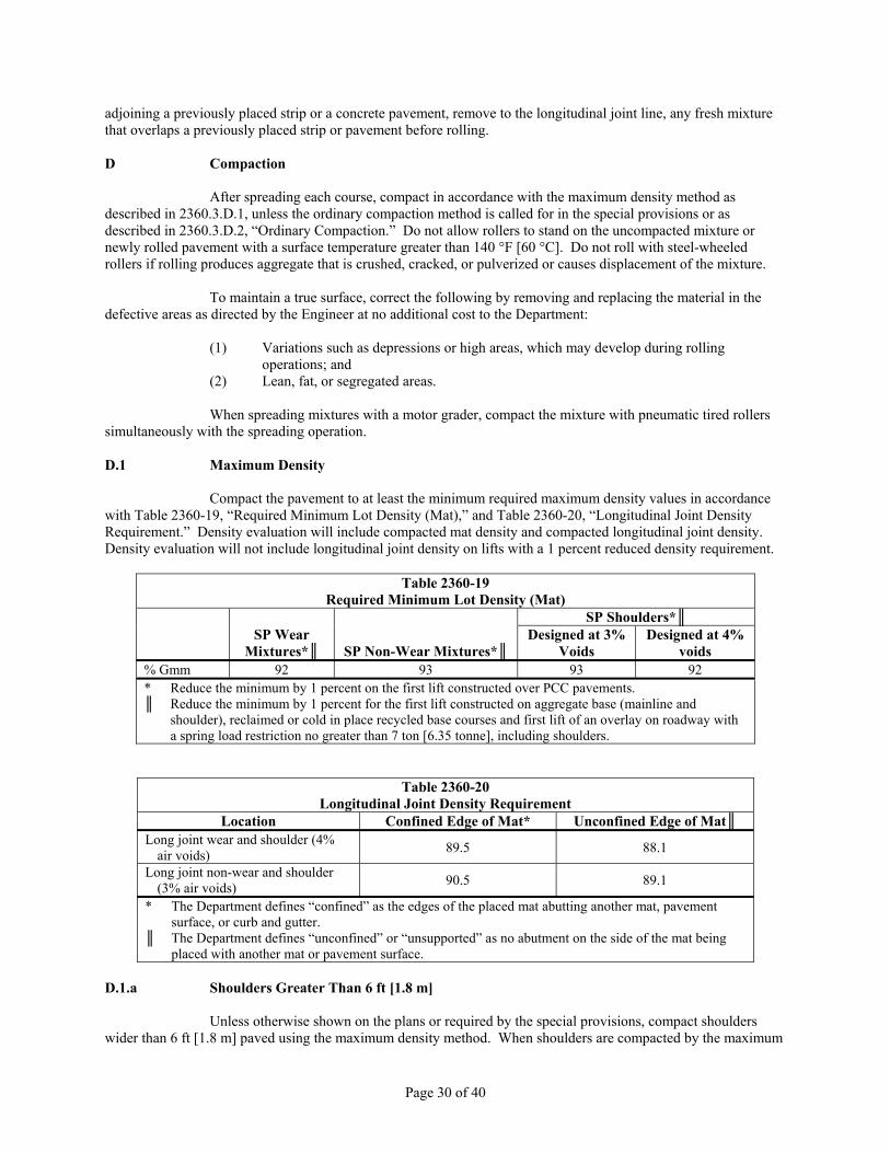
Page 30 of 40
adjoining a previously placed strip or a concrete pavement, remove to the longitudinal joint line, any fresh mixture that overlaps a previously placed strip or pavement before rolling. D Compaction
After spreading each course, compact in accordance with the maximum density method as described in 2360.3.D.1, unless the ordinary compaction method is called for in the special provisions or as described in 2360.3.D.2, “Ordinary Compaction.” Do not allow rollers to stand on the uncompacted mixture or newly rolled pavement with a surface temperature greater than 140 °F [60 °C]. Do not roll with steel-wheeled rollers if rolling produces aggregate that is crushed, cracked, or pulverized or causes displacement of the mixture.
To maintain a true surface, correct the following by removing and replacing the material in the defective areas as directed by the Engineer at no additional cost to the Department:
(1) Variations such as depressions or high areas, which may develop during rolling operations; and
(2) Lean, fat, or segregated areas.
When spreading mixtures with a motor grader, compact the mixture with pneumatic tired rollers simultaneously with the spreading operation. D.1 Maximum Density
Compact the pavement to at least the minimum required maximum density values in accordance with Table 2360-19, “Required Minimum Lot Density (Mat),” and Table 2360-20, “Longitudinal Joint Density Requirement.” Density evaluation will include compacted mat density and compacted longitudinal joint density. Density evaluation will not include longitudinal joint density on lifts with a 1 percent reduced density requirement.
Table 2360-19 Required Minimum Lot Density (Mat)
SP Wear
Mixtures*║ SP Non-Wear Mixtures*║
SP Shoulders*║ Designed at 3%
Voids Designed at 4%
voids % Gmm 92 93 93 92 * Reduce the minimum by 1 percent on the first lift constructed over PCC pavements. ║ Reduce the minimum by 1 percent for the first lift constructed on aggregate base (mainline and
shoulder), reclaimed or cold in place recycled base courses and first lift of an overlay on roadway with a spring load restriction no greater than 7 ton [6.35 tonne], including shoulders.
Table 2360-20 Longitudinal Joint Density Requirement
Location Confined Edge of Mat* Unconfined Edge of Mat║ Long joint wear and shoulder (4%
air voids) 89.5 88.1
Long joint non-wear and shoulder (3% air voids) 90.5 89.1
* The Department defines “confined” as the edges of the placed mat abutting another mat, pavement surface, or curb and gutter.
║ The Department defines “unconfined” or “unsupported” as no abutment on the side of the mat being placed with another mat or pavement surface.
D.1.a Shoulders Greater Than 6 ft [1.8 m]
Unless otherwise shown on the plans or required by the special provisions, compact shoulders wider than 6 ft [1.8 m] paved using the maximum density method. When shoulders are compacted by the maximum

Page 31 of 40
density method and are paved separately from the driving lane, or have a different required minimum density than the driving lane, delineate the lot tonnage placed on the shoulder in separate lots from the driving lanes for the day paving was conducted. D.1.b Shoulders Equal to or Less Than 6 ft [1.8 m]
Unless otherwise shown on the plans or required by the special provisions, use the ordinary compaction method in accordance with 2360.3.D.2 to compact a narrow shoulder no wider than 6 ft [1.8 m] paved in the same pass as a driving lane or paved separately. The Department will exclude mixture compacted under ordinary compaction from lot density requirements and from incentive or disincentive payment.
When compacting a narrow shoulder using the maximum density method, compact to densities in accordance with Table 2360-19. If the minimum required density of the shoulder is different than the driving lane, delineate the tonnage placed on the shoulder in separate lots from the driving lane. D.1.c Echelon Paving
The Department considers echelon paving, two pavers running next to each other in adjacent lanes, as separate operations. D.1.d Determination
Calculate each individual lot’s maximum density by averaging the results of the cores within the lot expressed as the percentage of the maximum specific gravity. Test fine graded mix in accordance with Laboratory Manual Method 1810. Test coarse graded mix in accordance with Laboratory Manual Method 1816 when directed by the Engineer. Determination of coarse or fine graded mixtures is based on the percentage of material passing the No. 8 [2.36 mm] sieve as defined in Table 2360-8.
Obtain the maximum specific gravity value for calculating the percentage density for the lot from the maximum gravity values taken from production tests during that day’s paving. If the production tests during that day’s paving result in only one or two maximum specific gravity values, use the moving average value at that test point. If production tests during that day’s paving result in three or more maximum specific gravity values, use the average of those tests alone as indicated above. D.1.e Timeline
Complete compaction within 8 h of mixture placement and before obtaining core samples. Only use pneumatic tired or static steel rollers for compaction performed between 6 h and 8 h after mixture placement. Do not reroll compacted mixtures with deficient densities. D.1.f Stop Production
If all the lots in a day’s production or greater than 50 percent of the lots on multiple days fail to meet the minimum density requirement, stop production, determine the source of the problem, and take corrective action to bring the work into compliance with specified minimum required density. D.1.g Lot Determination
Table 2360-21 Lot Determination
Daily Production, ton [tonne] Lots 300* – 600 [270* – 545] 1 601 – 1,000 [546 – 910] 2
1,001 – 1,600 [911 – 1,455] 3 1,601 – 2,600 [1,456 – 2,360] 4

Page 32 of 40
Table 2360-21 Lot Determination
Daily Production, ton [tonne] Lots 2,601 – 4,600 [2,361 – 4,175] 5
> 4,600 [4,175] ║ * If producing no greater than 300 ton [270 tonne] of mix, establish the first lot when the total
weight is greater than 300 ton [270 tonne]. ║ Add one lot for each additional 900 tons [820 tonne] or part thereof.
D.1.h Mat Density Cores
Obtain four cores in each lot. Take two cores from random locations as directed by the Engineer. Take the third and fourth cores, the companion cores, within 1 ft [0.3 m] longitudinally from the first two cores. Submit the companion cores to the Engineer immediately after coring and sawing. If the random core location falls on a longitudinal joint, cut the core with the outer edge of the core barrel 1 ft [0.3 m] away laterally from the edge of the top of the mat. Do not take cores for compacted mat density within 1 ft [300 mm] of any longitudinal joint. The Contractor is responsible for maintaining traffic, coring, patching the core holes, and sawing the cores to the paved lift thickness before density testing.
The Engineer may require additional density lots to isolate areas affected by equipment malfunction, heavy rain, or other factors affecting normal compaction operations. D.1.i Contractor Core Testing
Take and test cores at least 4 in [100 mm] in diameter at locations determined and marked by the Engineer.
Mark samples with the lot number and core number or letter. Transport the cores to the laboratory daily to prevent damage. Schedule the approximate time of testing during normal project work hours to allow the Engineer to observe the test and to record the saturated surface dry and immersed weight of the cores.
Determine the density by the end of the next working day after compaction. Measure each core three times for thickness before saw cutting. Report the average lift thickness on the core sheet. If placing multiple layers in a single day, saw and separate cores for each layer, test, and report by the end of the next working day. Place and compact mix into the coring hole to restore the surface within 24 h after coring or the Department will fine the Contractor $100 per working day per lot until restored. D.1.j Companion Core Testing
The Department will select at least one of the two companion cores per lot to test for verification. For lots designated as longitudinal joint density lots, the Department will test at least one of the mat density companion cores and at least one of the longitudinal joint density companion cores. D.1.k Tolerance Comparison D.1.k(1) Tolerance Comparison – Individual
Compare the individual core bulk specific gravities obtained by the Contractor and by the Department. If the bulk specific gravities differ by greater than 0.030, use the Department’s bulk specific gravity. D.1.k(2) Tolerance Comparison – Day’s Shrinking Tolerance
For a second comparison of the cores that pass the individual tolerance criteria, compare the average of the Contractor’s bulk specific gravities with the average of the Department’s bulk specific gravities.
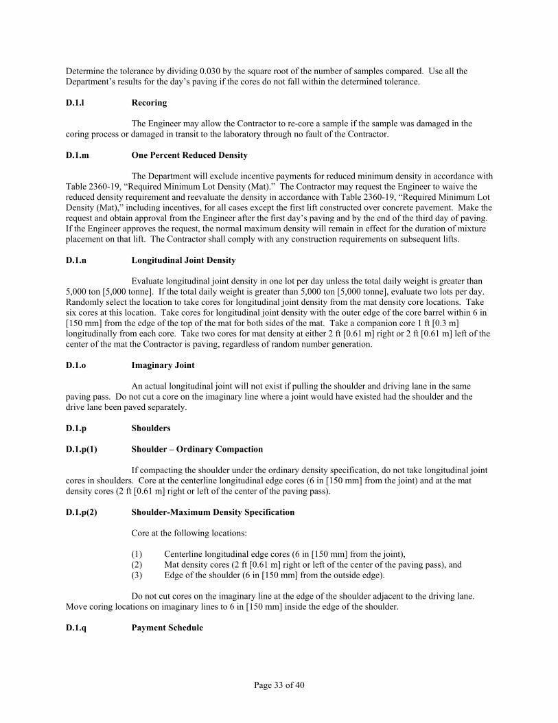
Page 33 of 40
Determine the tolerance by dividing 0.030 by the square root of the number of samples compared. Use all the Department’s results for the day’s paving if the cores do not fall within the determined tolerance. D.1.l Recoring
The Engineer may allow the Contractor to re-core a sample if the sample was damaged in the coring process or damaged in transit to the laboratory through no fault of the Contractor. D.1.m One Percent Reduced Density
The Department will exclude incentive payments for reduced minimum density in accordance with Table 2360-19, “Required Minimum Lot Density (Mat).” The Contractor may request the Engineer to waive the reduced density requirement and reevaluate the density in accordance with Table 2360-19, “Required Minimum Lot Density (Mat),” including incentives, for all cases except the first lift constructed over concrete pavement. Make the request and obtain approval from the Engineer after the first day’s paving and by the end of the third day of paving. If the Engineer approves the request, the normal maximum density will remain in effect for the duration of mixture placement on that lift. The Contractor shall comply with any construction requirements on subsequent lifts. D.1.n Longitudinal Joint Density
Evaluate longitudinal joint density in one lot per day unless the total daily weight is greater than 5,000 ton [5,000 tonne]. If the total daily weight is greater than 5,000 ton [5,000 tonne], evaluate two lots per day. Randomly select the location to take cores for longitudinal joint density from the mat density core locations. Take six cores at this location. Take cores for longitudinal joint density with the outer edge of the core barrel within 6 in [150 mm] from the edge of the top of the mat for both sides of the mat. Take a companion core 1 ft [0.3 m] longitudinally from each core. Take two cores for mat density at either 2 ft [0.61 m] right or 2 ft [0.61 m] left of the center of the mat the Contractor is paving, regardless of random number generation. D.1.o Imaginary Joint
An actual longitudinal joint will not exist if pulling the shoulder and driving lane in the same paving pass. Do not cut a core on the imaginary line where a joint would have existed had the shoulder and the drive lane been paved separately. D.1.p Shoulders D.1.p(1) Shoulder – Ordinary Compaction
If compacting the shoulder under the ordinary density specification, do not take longitudinal joint cores in shoulders. Core at the centerline longitudinal edge cores (6 in [150 mm] from the joint) and at the mat density cores (2 ft [0.61 m] right or left of the center of the paving pass). D.1.p(2) Shoulder-Maximum Density Specification
Core at the following locations:
(1) Centerline longitudinal edge cores (6 in [150 mm] from the joint), (2) Mat density cores (2 ft [0.61 m] right or left of the center of the paving pass), and (3) Edge of the shoulder (6 in [150 mm] from the outside edge).
Do not cut cores on the imaginary line at the edge of the shoulder adjacent to the driving lane.
Move coring locations on imaginary lines to 6 in [150 mm] inside the edge of the shoulder. D.1.q Payment Schedule

Page 34 of 40
Table 2360-22 Payment Schedule for Maximum Mat Density
SP Wear and SP Shoulders (4% Void) Density, %*
SP Non-Wear and SP Shoulders (3% Void), Density, %*
Mat Density Pay Factor A Traffic Level
2 & 3 Traffic Level
4 & 5≥ 93.6 ≥ 94.6 1.03║ 1.05║
93.1 – 93.5 94.1 – 94.5 1.02║ 1.04║ 92.0 – 93.0 93.0 – 94.0 1.00 1.00 91.0 – 91.9 92.0 – 92.9 0.98 0.98 90.5 – 90.9 91.5 – 91.9 0.95 0.95 90.0 – 90.4 91.0 – 91.4 0.91 0.91 89.5 – 89.9 90.5 – 90.9 0.85 0.85 89.0 – 89.4 90.0 – 90.4 0.70 0.70
< 89.0 < 90.0 † † * Calculate the percent of maximum specific gravity to the nearest tenth. ║ Payment will only apply if the day's weighted average individual production air voids fall within -
½ percent of the target air void value. Base the weighted average air voids on all the mixture production tests in accordance with 2360.2.G.7, “Production Tests” for the corresponding day and weight by the tons the corresponding test represents.
† The Department will pay for the HMA material represented by the lot at 70 percent of the relevant contract unit price, unless a single core density is less than 87.0 percent of the maximum specific gravity (Gmm). If a single core density is less than 87.0 percent of Gmm, the Engineer will decide if the mixture is subject to removal and replacement or reduced payment at 50 percent of the relevant contract unit price. If the Engineer decides the material needs to be removed and replace, the Contractor will remove and replace the material at no additional cost to the Department. Use additional core samples to determine the limits of the removal and replacement area. Take additional core samples at the same offset from centerline as the original core. If the original low density core was taken within 1½ ft [0.45 m] of an edge of the paver pass, take additional cores at 1½ ft [0.45 m from the edge of the paver pass. Determine the densities at 50 ft [15 m] intervals both ahead and behind the point of unacceptable core density until finding a point of acceptable core density. If the incremental core density testing extends into a previously accepted lot, remove the unacceptable material. Do not use to the test results to recalculate the previously accepted lot density. Perform additional coring and testing for unacceptable core density at no additional cost to the Department. The Department will calculate the area of unacceptable pavement as the product of the longitudinal limits as determined by the 50 ft [15 m] cores and the full width of the paver pass, laying in the traffic lane or lanes. The Department will exempt shoulders from this calculation unless density failure occurred in the shoulder area. After removing and replacing the unacceptable material, determine the density of the replacement material by averaging the two cores. The Department will pay for the replacement material in accordance with Table 2360-22 or Table 2360-23. The Department will not pay for material removed. The Department will pay for the remainder of the original lot at 70 percent of the relevant contract unit price.
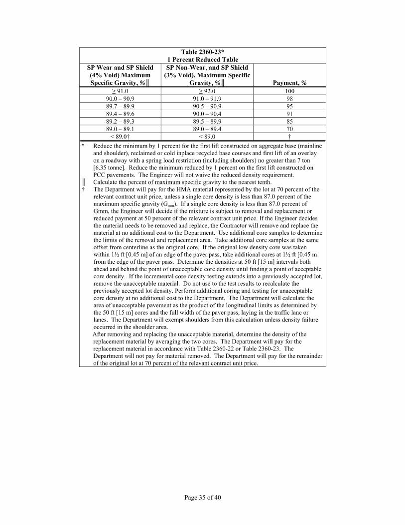
Page 35 of 40
Table 2360-23* 1 Percent Reduced Table
SP Wear and SP Shield (4% Void) Maximum Specific Gravity, %║
SP Non-Wear, and SP Shield (3% Void), Maximum Specific
Gravity, %║ Payment, % ≥ 91.0 ≥ 92.0 100
90.0 – 90.9 91.0 – 91.9 98 89.7 – 89.9 90.5 – 90.9 95 89.4 – 89.6 90.0 – 90.4 91 89.2 – 89.3 89.5 – 89.9 85 89.0 – 89.1 89.0 – 89.4 70
< 89.0† < 89.0 † * Reduce the minimum by 1 percent for the first lift constructed on aggregate base (mainline
and shoulder), reclaimed or cold inplace recycled base courses and first lift of an overlay on a roadway with a spring load restriction (including shoulders) no greater than 7 ton [6.35 tonne]. Reduce the minimum reduced by 1 percent on the first lift constructed on PCC pavements. The Engineer will not waive the reduced density requirement.
║ Calculate the percent of maximum specific gravity to the nearest tenth. † The Department will pay for the HMA material represented by the lot at 70 percent of the
relevant contract unit price, unless a single core density is less than 87.0 percent of the maximum specific gravity (Gmm). If a single core density is less than 87.0 percent of Gmm, the Engineer will decide if the mixture is subject to removal and replacement or reduced payment at 50 percent of the relevant contract unit price. If the Engineer decides the material needs to be removed and replace, the Contractor will remove and replace the material at no additional cost to the Department. Use additional core samples to determine the limits of the removal and replacement area. Take additional core samples at the same offset from centerline as the original core. If the original low density core was taken within 1½ ft [0.45 m] of an edge of the paver pass, take additional cores at 1½ ft [0.45 m from the edge of the paver pass. Determine the densities at 50 ft [15 m] intervals both ahead and behind the point of unacceptable core density until finding a point of acceptable core density. If the incremental core density testing extends into a previously accepted lot, remove the unacceptable material. Do not use to the test results to recalculate the previously accepted lot density. Perform additional coring and testing for unacceptable core density at no additional cost to the Department. The Department will calculate the area of unacceptable pavement as the product of the longitudinal limits as determined by the 50 ft [15 m] cores and the full width of the paver pass, laying in the traffic lane or lanes. The Department will exempt shoulders from this calculation unless density failure occurred in the shoulder area. After removing and replacing the unacceptable material, determine the density of the replacement material by averaging the two cores. The Department will pay for the replacement material in accordance with Table 2360-22 or Table 2360-23. The Department will not pay for material removed. The Department will pay for the remainder of the original lot at 70 percent of the relevant contract unit price.
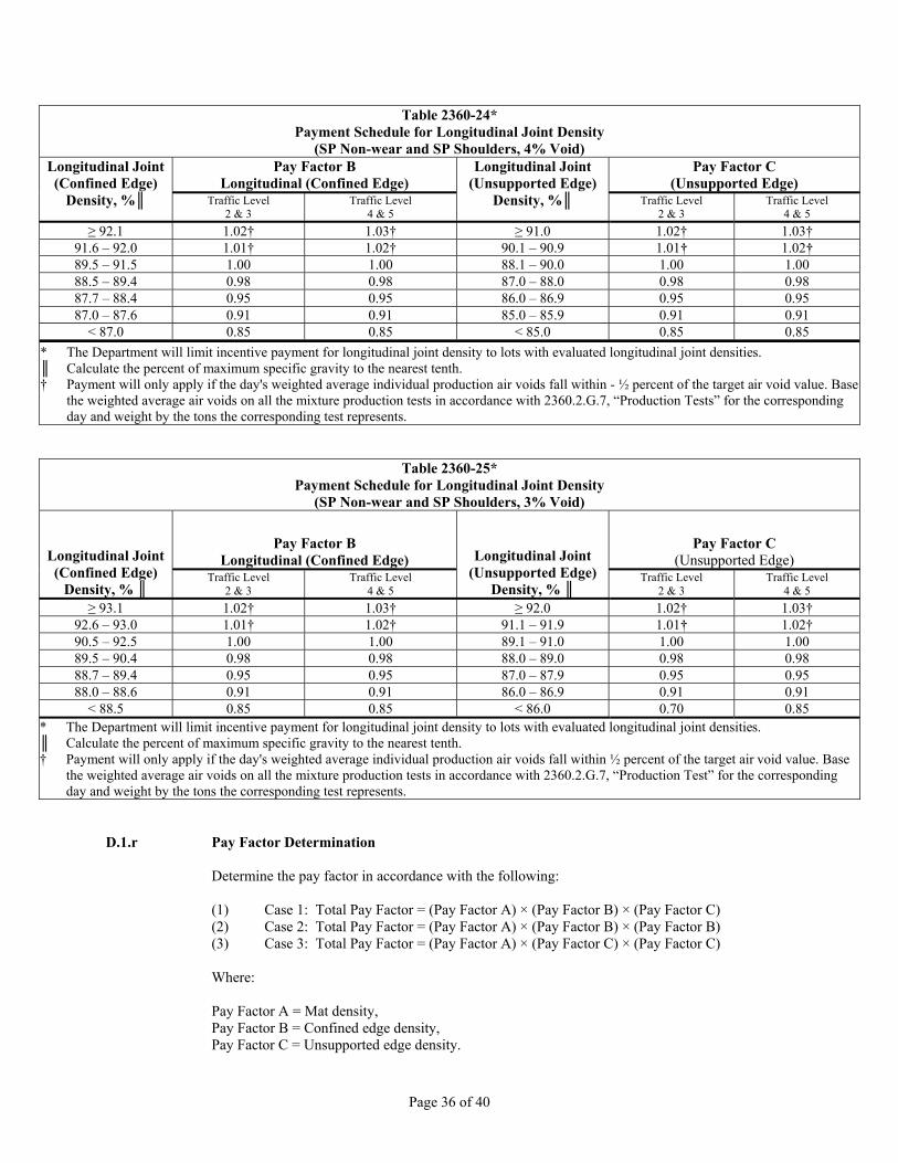
Page 36 of 40
Table 2360-24* Payment Schedule for Longitudinal Joint Density
(SP Non-wear and SP Shoulders, 4% Void) Longitudinal Joint (Confined Edge)
Density, %║
Pay Factor B Longitudinal (Confined Edge)
Longitudinal Joint (Unsupported Edge)
Density, %║
Pay Factor C (Unsupported Edge)
Traffic Level 2 & 3
Traffic Level 4 & 5
Traffic Level 2 & 3
Traffic Level 4 & 5
≥ 92.1 1.02† 1.03† ≥ 91.0 1.02† 1.03† 91.6 – 92.0 1.01† 1.02† 90.1 – 90.9 1.01† 1.02† 89.5 – 91.5 1.00 1.00 88.1 – 90.0 1.00 1.00 88.5 – 89.4 0.98 0.98 87.0 – 88.0 0.98 0.98 87.7 – 88.4 0.95 0.95 86.0 – 86.9 0.95 0.95 87.0 – 87.6 0.91 0.91 85.0 – 85.9 0.91 0.91
< 87.0 0.85 0.85 < 85.0 0.85 0.85 * The Department will limit incentive payment for longitudinal joint density to lots with evaluated longitudinal joint densities. ║ Calculate the percent of maximum specific gravity to the nearest tenth. † Payment will only apply if the day's weighted average individual production air voids fall within - ½ percent of the target air void value. Base
the weighted average air voids on all the mixture production tests in accordance with 2360.2.G.7, “Production Tests” for the corresponding day and weight by the tons the corresponding test represents.
Table 2360-25* Payment Schedule for Longitudinal Joint Density
(SP Non-wear and SP Shoulders, 3% Void)
Longitudinal Joint (Confined Edge)
Density, % ║
Pay Factor B Longitudinal (Confined Edge) Longitudinal Joint
(Unsupported Edge) Density, % ║
Pay Factor C (Unsupported Edge)
Traffic Level 2 & 3
Traffic Level 4 & 5
Traffic Level 2 & 3
Traffic Level 4 & 5
≥ 93.1 1.02† 1.03† ≥ 92.0 1.02† 1.03† 92.6 – 93.0 1.01† 1.02† 91.1 – 91.9 1.01† 1.02† 90.5 – 92.5 1.00 1.00 89.1 – 91.0 1.00 1.00 89.5 – 90.4 0.98 0.98 88.0 – 89.0 0.98 0.98 88.7 – 89.4 0.95 0.95 87.0 – 87.9 0.95 0.95 88.0 – 88.6 0.91 0.91 86.0 – 86.9 0.91 0.91
< 88.5 0.85 0.85 < 86.0 0.70 0.85 * The Department will limit incentive payment for longitudinal joint density to lots with evaluated longitudinal joint densities. ║ Calculate the percent of maximum specific gravity to the nearest tenth. † Payment will only apply if the day's weighted average individual production air voids fall within ½ percent of the target air void value. Base
the weighted average air voids on all the mixture production tests in accordance with 2360.2.G.7, “Production Test” for the corresponding day and weight by the tons the corresponding test represents.
D.1.r Pay Factor Determination
Determine the pay factor in accordance with the following:
(1) Case 1: Total Pay Factor = (Pay Factor A) × (Pay Factor B) × (Pay Factor C) (2) Case 2: Total Pay Factor = (Pay Factor A) × (Pay Factor B) × (Pay Factor B) (3) Case 3: Total Pay Factor = (Pay Factor A) × (Pay Factor C) × (Pay Factor C)
Where:
Pay Factor A = Mat density, Pay Factor B = Confined edge density, Pay Factor C = Unsupported edge density.

Page 37 of 40
Use a pay factor of 1.00 for Pay Factor B, Pay Factor C, or both in lots where no cores are taken at the longitudinal joint. D.2 Ordinary Compaction
Perform ordinary compaction for the following:
(1) Layers identified in the typical sections with a minimum planned thickness less than 1½ in [40 mm],
(2) Thin lift leveling, (3) Wedging layers, (4) Patching layers, (5) Driveways, and (6) Areas the Contractor cannot compact with standard highway construction equipment.
If using the ordinary compaction method to evaluate density, use a control strip to establish a
rolling pattern. Use the rolling pattern to compact the asphalt mixture for the layer on which the control strip is constructed or until constructing a new control strip. The Engineer may waive the control strip requirement in small localized areas or other areas not conducive to its establishment. D.2.a Control Strip
Construct a control strip at least 395 sq. yd [330 sq. m] and of the same thickness as the lift the control strip represents at the beginning of the work on each lift of each course. Begin compacting immediately after spreading the mixture. Continue compacting until additional roller coverage does not produce appreciable increase in density. Determine densities by means of a portable nuclear testing device or approved alternate and create a growth curve to determine the optimum rolling pattern. Provide documentation of the growth curve to the Engineer. Roll the remainder of that course in accordance with the pattern developed in the test strip for that roller. Provide a new control strip in accordance with the following:
(1) If using a new JMF with a proportion change greater than 10 percent when compared to the currently produced mixture for a single stockpile aggregate,
(2) If changing the source of either aggregate or binder, or (3) After 10 days of production.
D.2.b Equipment
Use rollers that meet the requirements in 2360.3.B.2.e. Use the same equipment type and weight on the remainder of the pavement course that was used to construct the control strip. Provide at least two rollers. Provide a tandem steel wheeled roller for final rolling. The Contractor may use trench rollers or mechanical tampers to compact areas inaccessible to the conventional type rolling equipment. D.2.c Mixture Temperature
Refer to Table 2360-26, “Minimum Temperature Control” for the minimum laydown temperatures in all courses of the asphalt mixture as measured behind the paver or spreading machine. Do not pave when the air temperature is less than 32° F [0° C] unless otherwise directed by the Engineer in writing.

Page 38 of 40
Table 2360-26* Minimum Temperature Control
Air Temperature,
°F [°C]
Compacted Mat Thickness, †
1 in [25 mm] 1½ in [40 mm] 2 in [50 mm] >3 in [75 mm] 32 – 40 [0-5] — 265[129] ║ 255 [124] 250 [121] 41 – 50 [6-10] 270 [130] ║ 260 [127] 250 [121] 245 [118]
51 – 60 [11-15] 260 [127] ║ 255 [124] 245 [118] 240 [115] 61 – 70 [16-21] 250 [121] ║ 245 [118] 240 [115] 235 [113] 71 – 80 [22-27] 245 [118] 240 [115] 235 [113] 235 [113] 81 – 90 [28-32] 235 [113] 230 [110] 230 [110] 230 [110]
≥ 91 [33] 230 [110] 230 [110] 230 [110] 225 [107] * Not applicable if using a Warm Mix Asphalt (WMA) additive or process ║ Use at least one pneumatic-tire roller for intermediate rolling unless otherwise directed by the
Engineer. The Engineer may specify or modify the minimum laydown temperature in writing. † Based on the lift thicknesses shown on the plans.
E Surface Requirements
After compaction, the finished surface of each lift shall be reasonably free of segregated, open and torn sections, and shall be smooth and true to the grade and cross section shown on the plans with the following tolerances:
Table 2360-26 Surface Requirements
Course/Location Description ToleranceLeveling/1st lift using automatics
Tolerance also applies to 1st lift placed other than leveling when automatics are used. ½ in [15 mm]
Wear Tolerance of final 2 lifts from the edge of a 10 foot [3 m] straightedge laid parallel to or at right angles to the centerline. ¼ in [6 mm]
Shoulder Wear, Temporary Wear & bypasses
Tolerance from the edge of a 10 foot [3 m] straightedge laid parallel to or at right angles to the centerline. ¼ in [6 mm]
Transverse joints/construction joints
Tolerance from the edge of a 10 foot [3 m] straightedge centered longitudinally across the transverse joint. Correction by diamond
grinding required when directed by the Engineer. ¼ in [6 mm]
Transverse Slope Tolerance for surface of each lift exclusive of final shoulder wear.
Not to vary by more than 0.4 % from
plans.
Distance from edge of each lift and established centerline.
No less than the plan distance or more than 3 inches [75 mm] greater than the plan distance. The edge alignment of the wearing lift on tangent sections and on curve sections of 3 degrees or less can’t deviate from the established alignment by more than 1 inch
[25 mm] in any 25 foot [7.5 m] section.
See Description
Final wear adjacent to concrete pavements.
After compaction the final lift wear adjacent to concrete pavements must be slightly higher but not to exceed 1/4” [6mm]
than the concrete surface.
See Description
Final wear adjacent to fixed structures.
After compaction the final lift wear adjacent to gutters, manholes, pavement headers, or other fixed structures must be slightly higher
but not to exceed 1/4” [6mm] than the surface of the structure.
See Description
Finished surface of each lift.
Must be free of segregated and open and torn sections and deleterious material.
See Description

Page 39 of 40
Cut or saw and then remove and replace material placed outside the described limitations at no additional cost to the Department. If the Engineer determines the material can remain in place outside the limits, the Department will pay for the material at a reduced cost of $10 per sq. yd [$12 per sq. m]. The Department will consider any single occurrence of material outside the limitations to have a minimum dimension of at least 1 sq. yd [1 sq. m] in any dimension.
In addition to the list the above the pavement surface must meet requirements of 2399 (Pavement Surface Smoothness) requirements. E.1 Lift Thickness
After compaction, the thickness of each lift shall be within a tolerance of ¼ in [6 mm] of the thickness shown on the plans, except that, if automatic grade controls are used, this thickness requirement will not apply to the first lift placed. This thickness requirement will not apply to a leveling lift whether or not automatic grade controls are required. The Engineer may require removal and replacement of any part of any lift that is constructed to less than the minimum required thickness, at no additional cost to the Department.
Measure cores taken for density determination for thickness also. Measure each core three times for thickness before sawing. Report the average of these three measurements. Document each lot's average core thickness and submit to the Engineer. If the average of the two Contractor cores exceed the specified tolerance, an additional two cores may be taken in the lot in question. The Engineer will use the average of all core thickness measurements per day per lift to determine daily compliance with thickness specifications.
On that portion of any lift constructed to more than the maximum permissible thickness, the
materials used in the excess mixture above that required to construct that portion of the lift to the plan thickness plus ¼ in [6 mm] may be excluded from the pay quantities or at the discretion of the Engineer and at the Contractor's expense may be required to be removed and replaced. F Asphalt Mixture Production (FOB Department Trucks)
Produce asphalt mixture for the Department. Load the mixture being produced onto Department furnished trucks at the mixing plant at a time agreed on by the Engineer and Contractor. The Engineer will notify the Contractor of the total quantity of mixture required not less than 2 weeks prior to completion of the final wearing course. The Engineer will not accept the asphalt mixture if it is unsuitable for the intended use. G Small Quantity Paving
A MDR is not required for planned project quantities less than 9,000 sq. yd inches (4,500 sq. yd per 2-inch thickness, etc) [191,200 m2 mm] or 500 ton [450 tonne]. Verify in writing that the asphalt mixture delivered to the project meets the requirements of Table 3139-3 and Table 2360-7, “Mixture Requirements.” The Department will obtain samples, as determined by the Engineer, to verify mixture requirements and to perform material acceptance in accordance with 2360.2.G.14.b, “Isolated Failures at Mixture Start-Up — Production Air Voids,” 2360.2 G.14.c, “Individual Failure — Gradation, Percent Asphalt Binder, Production Air Voids, and Adj. AFT,” and 2360.2.G.14.h, “Coarse and Fine Aggregate Crushing Failure.” 2360.4 METHOD OF MEASUREMENT
When paying for material by weight, the Engineer will measure separately asphalt mixture of each type by weight based on the total quantity of material hauled from the mixing plant. The Engineer will not make deductions for the asphalt materials.
When paying for material by area, the Engineer will separately measure asphalt mixture of each type and for each specific lift by area and by thickness on the basis of actual final dimensions placed. 2360.5 BASIS OF PAYMENT

Page 40 of 40
The contract unit price for asphalt mixture used in each course includes the cost of constructing the asphalt surfacing and providing and incorporating asphalt binder, mineral filler, hydrated lime. Anti-stripping additives may be permitted or required as indicated in 2360.2.C.
The Department will pay for additives required by the contract at the relevant contract unit price for the mixture. The Department will pay for additives incorporated as directed by the Engineer as extra work in accordance with 1403, “Extra Work.”
The Department will apply reduced payment if the mixture includes steel slag as one of the aggregate proportions and the production lab density at the design gyrations at the recommended or established asphalt content is greater than 160 lb per cu. ft [2,565 kg per cu. m]. The Department will pay for the mixture at the contract unit price, calculated as follows:
160)160____(100(100% −×−
=gyrationsdesignatdensityproductionPayment
⎥⎦
⎤⎢⎣
⎡ −×−=
565,2)565,2____(100(100% gyrationsdesignatdensityproductionPayment
If the plans do not show a contract pay item for shoulder surfacing and other special construction,
the Department will include payment for the quantities of material used for these purposes in the payment for the wearing course materials.
Complete yield checks and monitor thickness determinations to construct the work as shown on the plans. Use the tolerances for lift thickness in accordance with 2360.3.E, “Surface Requirements” and surface smoothness requirements in accordance with 2399 for occasional variations and not for continuous over-running or under-running, unless otherwise required by the Engineer.
The contract unit price for asphalt mixture production includes the cost of the material and loading onto Department-provided trucks at the mixing plant.
The Department will pay for plant mixed asphalt pavement on the basis of the following schedule:
Item No.: Item: Unit: 2360.501 Type SP* Wearing Course Mixture †‡ ton [metric ton] 2360.502 Type SP* Non-Wearing Course Mixture †‡ ton [metric ton] 2360.503 Type SP*║ Course Mixture †‡# in [mm] thick, square yard [square meter] 2360.504 Type SP*║ Course Mixture †‡ square yard [square meter] 2360.505 Type SP * Bituminous Mixture for Specified Purpose ton [metric ton] 2360.506 Type SP * Bituminous Mixture Production ton [metric ton] * Aggregate size Designation, 9.5, 12.5 or 19 as appropriate, see 2360.1.A.3. ║ “Wearing” or “Non Wearing” as appropriate. † Traffic level in accordance with Table 2360-1, “Traffic Levels.” ‡ AC binder grade designation (Table 2360-2). # Lift thickness shown on the plans.