2400 vertical carousel - jtechcom.com 2400 vertical carousel installation, operation, and...
TRANSCRIPT
Series 2400 Vertical Carousel Installation, Operation, and Maintenance Manual
These instructions are intended for use with all White Vertical Carousel models equipped with AC drives including:
MODEL NOMINAL PAN DEPTH
2400 24.5 inches 1800 18.5 inches 1600 16.5 inches 1500 15.5 inches
Document Number: 42805 Revision: 5.3
For assistance, contact oCustomer One Protectiotechnical support group a1-800-571-8822 or [email protected]
ur n t

SERIES 2400 VERTICAL CAROUSEL INSTALLATION, OPERATION, AND MAINTENANCE MANUAL White Systems, Inc. 30 Boright Avenue Kenilworth, NJ 07033 Phone 908.272.6700 • Fax 908.272.5920 Document Number: 42805 Revision: 5.3 Printing: 29 January 2000 Copyright 2000 White Systems, Inc. All rights reserved. This document contains information that is proprietary to White Systems, Inc. (White). This document and the information contained in it may not be duplicated, used, or disclosed in whole or in part, except as specifically authorized in writing by White. Brand and product names mentioned herein are trademarks or registered trademarks of their respective holders. The information contained in this document is subject to change without notice and shall supersede all previous versions of the document. There are no warranties with respect to the information contained in this document, express or implied, except as provided by written contract between White and customer.


V E R T I C A L C A R O U S E L T E C H N I C A L M A N U A L
White Systems, Inc. i
PREFACE Purpose of this manual
This is a guide for installing, operating, and maintaining the Series 2400 Vertical Carousel. The equipment owner should make a copy of this manual available to employees at installation and during safety, operation, and maintenance training. Afterwards, maintenance personnel should keep a copy on file for reference during maintenance, troubleshooting, or when ordering spare parts.
This manual does not cover major rebuilds and overhauls, or component level electronic repairs. Should you encounter any of these situations, please call our Customer One Protection technical support group at 1-800-571-8822.
How to use this manual For reference purposes, we have divided this manual into separate subjects. Each subject appears in a numbered section following a bold, capitalized title. Key paragraphs within each section are numbered and have bold titles. The Table of Contents lists the numbered sections and paragraphs, forming an index for quick reference.
When possible, we have included illustrations to help explain procedures. Refer to the List of Figures to find specific illustrations. For cases where generic drawings cannot provide adequate detail, we will refer to specific drawings shipped with this manual.
Organization of this manual 1. SAFETY: This section is a list of statements and symbols the
manual uses to warn about procedures that, if followed incorrectly, could cause personal injury or equipment damage.
2. DESCRIPTION: This section describes the components of the vertical carousel system, how the system operates, and the system’s operating controls.
3. INSTALLATION: This section contains a list of tools, components, and procedures for the electrical and mechanical installation of the Series 2400 Vertical Carousel.
4. ADJUSTMENTS AND SETUP: This section is a general guideline for commissioning the Series 2400 Vertical Carousel.

V E R T I C A L C A R O U S E L T E C H N I C A L M A N U A L
ii White Systems, Inc.
5. OPERATION: This section contains rules for safe operation and procedures for starting and operating the vertical carousel system in manual and automatic mode.
6. MAINTENANCE AND TROUBLESHOOTING: This section contains rules for maintenance safety, a recommended maintenance schedule, procedures for inspecting, adjusting, and replacing components, and a guide for troubleshooting system problems.
7. DESIGN DATA: This section contains a list of Series 2400 Vertical Carousel specifications and optional equipment.

V E R T I C A L C A R O U S E L T E C H N I C A L M A N U A L
White Systems, Inc. iii
Table of Contents 1. SAFETY................................................................................................................................................. 1
1.1 WARNINGS ................................................................................................................................... 1 1.2 CAUTIONS .................................................................................................................................... 1 1.3 APPLICABLE WARNINGS AND CAUTIONS............................................................................ 1
2. DESCRIPTION..................................................................................................................................... 3 2.1 GENERAL...................................................................................................................................... 3 2.2 OPERATING CONTROLS............................................................................................................ 5
2.2.1 Location of operating controls................................................................................................ 5 2.2.2 Carousel Interface Terminal ................................................................................................... 5
2.3 THEORY OF OPERATION........................................................................................................... 7 2.3.1 Enclosure ................................................................................................................................ 7 2.3.2 Conveying mechanism............................................................................................................. 7 2.3.3 Controls................................................................................................................................... 9
3. INSTALLATION................................................................................................................................ 12 3.1 TOOLS AND EQUIPMENT ........................................................................................................ 12 3.2 REFERENCE DRAWINGS ......................................................................................................... 12 3.3 RESOURCE PLANNING............................................................................................................. 12 3.4 INSTALLATION SITE ................................................................................................................ 12 3.5 UNCRATING ............................................................................................................................... 13
3.5.1 Inspection.............................................................................................................................. 13 3.5.2 Itemized parts checklist ......................................................................................................... 13
3.6 ASSEMBLING THE CAROUSEL ENCLOSURE ...................................................................... 15 3.6.1 Layout ................................................................................................................................... 15 3.6.2 Uncrating the carousel sides................................................................................................. 16 3.6.3 Placing the left carousel side ................................................................................................ 18 3.6.4 Placing the right carousel side ............................................................................................. 20 3.6.5 Installing the crossbars......................................................................................................... 21 3.6.6 Installing the torque shaft ..................................................................................................... 22 3.6.7 Installing the tie rods ............................................................................................................ 24 3.6.8 Installing the spreaders......................................................................................................... 24 3.6.9 Installing the skin panels....................................................................................................... 25 3.6.10 Adjusting the tie rods ............................................................................................................ 27 3.6.11 Leveling the carousel ............................................................................................................ 28 3.6.12 Anchoring the carousel ......................................................................................................... 29
3.7 ELECTRO-MECHANICAL WIRING ......................................................................................... 30 3.7.1 Control enclosure.................................................................................................................. 30 3.7.2 Carousel Interface Terminal ................................................................................................. 31 3.7.3 Task light............................................................................................................................... 31 3.7.4 Drive ..................................................................................................................................... 31
4. ADJUSTMENTS AND SETUP ......................................................................................................... 32 4.1 ADJUSTING CONVEYING MECHANISM............................................................................... 32
4.1.1 Adjusting the load chains...................................................................................................... 32 4.1.2 Adjusting the drive mechanism ............................................................................................. 33
4.2 CONNECTING POWER.............................................................................................................. 34 4.2.1 Power requirements .............................................................................................................. 34

V E R T I C A L C A R O U S E L T E C H N I C A L M A N U A L
iv White Systems, Inc.
4.2.2 Courtesy outlets..................................................................................................................... 34 4.2.3 Connecting power to the carousel......................................................................................... 34 4.2.4 Powering the electrical enclosure......................................................................................... 35
4.3 FINAL ASSEMBLY..................................................................................................................... 35 4.3.1 Installing the pans................................................................................................................. 35 4.3.2 Installing the counter ............................................................................................................ 37 4.3.3 Installing the doors ............................................................................................................... 37 4.3.4 Installing the last four pans................................................................................................... 40 4.3.5 Leveling the pans .................................................................................................................. 40 4.3.6 Installing the reference sensor reflector................................................................................ 41 4.3.7 Installing the lower access panel .......................................................................................... 43
5. OPERATION ...................................................................................................................................... 45 5.1 RULES FOR SAFE OPERATION ............................................................................................... 45 5.2 LOADING THE CAROUSEL...................................................................................................... 45
5.2.1 Pan weight capacity .............................................................................................................. 45 5.2.2 Carousel weight capacity ...................................................................................................... 45 5.2.3 Loading method..................................................................................................................... 45
5.3 STARTING THE CAROUSEL .................................................................................................... 47 5.4 OPERATING MODES ................................................................................................................. 48
5.4.1 Host computer mode ............................................................................................................. 48 5.4.2 Position carousel................................................................................................................... 48 5.4.3 Jog/move carousel................................................................................................................. 49 5.4.4 Home carousel ...................................................................................................................... 49 5.4.5 Lightbar monitor (optional) .................................................................................................. 50 5.4.6 Door control (optional)......................................................................................................... 50
5.5 FAULTS........................................................................................................................................ 50 5.5.1 Emergency stop fault............................................................................................................. 50 5.5.2 Light curtain/touch bar fault ................................................................................................. 51 5.5.3 Execution fault ...................................................................................................................... 51 5.5.4 Photo eye fault ...................................................................................................................... 52 5.5.5 Imbalance fault ..................................................................................................................... 52
5.6 SETUP PARAMETERS ............................................................................................................... 52 5.6.1 Password............................................................................................................................... 52 5.6.2 Set parameters....................................................................................................................... 53 5.6.3 Checksums............................................................................................................................. 53 5.6.4 Pulses per revolution............................................................................................................. 53 5.6.5 Number of pans ..................................................................................................................... 54 5.6.6 Offset ..................................................................................................................................... 54 5.6.7 Low speed.............................................................................................................................. 54 5.6.8 Stop window .......................................................................................................................... 55 5.6.9 Set boards.............................................................................................................................. 55 5.6.10 Baud rate............................................................................................................................... 56 5.6.11 Data bits................................................................................................................................ 56 5.6.12 Parity..................................................................................................................................... 56 5.6.13 Stop bits................................................................................................................................. 57 5.6.14 Save settings.......................................................................................................................... 57
6. MAINTENANCE AND TROUBLESHOOTING............................................................................. 58 6.1 MAINTENANCE SAFETY.......................................................................................................... 58 6.2 MAINTENANCE SCHEDULE.................................................................................................... 59 6.3 CAROUSEL INSPECTION.......................................................................................................... 59
6.3.1 Hardware .............................................................................................................................. 59 6.3.2 Checking drive chain............................................................................................................. 59 6.3.3 Checking drive sprockets ...................................................................................................... 60
V E R T I C A L C A R O U S E L T E C H N I C A L M A N U A L
White Systems, Inc. v
6.3.4 Checking load chain ............................................................................................................. 60 6.3.5 Checking load chain wheels.................................................................................................. 60 6.3.6 Checking stabilizing arm wheels........................................................................................... 60 6.3.7 Checking scissors arms ......................................................................................................... 60 6.3.8 Checking pans and shelves ................................................................................................... 60 6.3.9 Checking the stabilizing track............................................................................................... 60 6.3.10 Checking photo eyes ............................................................................................................. 60
6.4 CAROUSEL MAINTENANCE.................................................................................................... 61 6.4.1 Checking reducer oil level .................................................................................................... 61 6.4.2 Replacing oil in reducer........................................................................................................ 61 6.4.3 Lubricating roller chain........................................................................................................ 61 6.4.4 Lubricating idler and drive sprocket bearings...................................................................... 61 6.4.5 Lubricating stabilizing track ................................................................................................. 61 6.4.6 Lubricating trunnion pivot points ......................................................................................... 61 6.4.7 Replacing sensors and cables ............................................................................................... 61
6.5 TROUBLESHOOTING GUIDE .................................................................................................. 62 7. DESIGN DATA................................................................................................................................... 63
7.1 SPECIFICATIONS....................................................................................................................... 63 7.1.1 Performance.......................................................................................................................... 63 7.1.2 Load chain safety factor........................................................................................................ 63 7.1.3 Bearings ................................................................................................................................ 63 7.1.4 Footprint ............................................................................................................................... 63 7.1.5 Height.................................................................................................................................... 63 7.1.6 Power requirements .............................................................................................................. 63 7.1.7 Environmental considerations .............................................................................................. 63 7.1.8 Sound level ............................................................................................................................ 63 7.1.9 Service life............................................................................................................................. 63
7.2 OPTIONAL EQUIPMENT........................................................................................................... 64 7.2.1 Dust cover ............................................................................................................................. 64 7.2.2 Hand crank ........................................................................................................................... 65 7.2.3 Clean room options............................................................................................................... 67 7.2.4 RS-232 interface port operation and message format .......................................................... 71
8. APPENDIX.......................................................................................................................................... 75 8.1 MODEL NUMBER ...................................................................................................................... 75 8.2 WARRANTY................................................................................................................................ 76 8.3 RETURNED GOODS................................................................................................................... 77 8.4 RECOMMENDED SPARE PARTS............................................................................................. 78

V E R T I C A L C A R O U S E L T E C H N I C A L M A N U A L
vi White Systems, Inc.
List of Figures FIGURE 1. THE VERTICAL CAROUSEL 3 FIGURE 2. CONTROLS AND INDICATORS 5 FIGURE 3. VERTICAL CAROUSEL ASSEMBLY 6 FIGURE 4. CONVEYING MECHANISM 8 FIGURE 5. ELECTRICAL ENCLOSURE 10 FIGURE 6. INTERNAL FRAMEWORK 14 FIGURE 7. UNCRATING SIDES 16 FIGURE 8. TRANSPORTING SIDES 17 FIGURE 9. POSITIONING SIDE FOR LIFTING 18 FIGURE 10. SLING ATTACHMENT FOR LIFTING 19 FIGURE 11. LIFTING THE SIDE 20 FIGURE 12. POSITIONING THE SIDE 21 FIGURE 13. CROSSBAR ATTACHMENT 22 FIGURE 14. LOWER END OF CHAIN TRACK 22 FIGURE 15. TORQUE SHAFT INSTALLATION 24 FIGURE 16. SPREADER INSTALLATION 25 FIGURE 17. PANEL INSTALLATION 26 FIGURE 18. TIE ROD ADJUSTMENT 27 FIGURE 19. FRONT-TO-BACK LEVELING 28 FIGURE 20. SIDE-TO-SIDE LEVELING 29 FIGURE 21. CAROUSEL ANCHORING 30 FIGURE 22. LOAD CHAIN ADJUSTMENT 32 FIGURE 23. CURVED TRACK ADJUSTMENT 33 FIGURE 24. GEAR MOTOR ADJUSTMENTS 34 FIGURE 25. PAN INSTALLATION 36 FIGURE 26. COUNTER INSTALLATION 37 FIGURE 27. DOOR INSTALLATION 38 FIGURE 28. DOOR INSTALLATION (130-INCH WIDE PANS) 40 FIGURE 29. REFERENCE SENSOR INSTALLATION 42 FIGURE 30. ACCESS PANEL INSTALLATION 43 FIGURE 31. ACCESS PANEL INSTALLATION (130-INCH WIDE PANS) 44 FIGURE 32. PAN LOADING 46 FIGURE 33. DUST COVER INSTALLATION 64 FIGURE 34. HAND CRANK INSTALLATION 66 FIGURE 35. PNEUMATIC DOOR ASSEMBLY 67 FIGURE 36. LIGHT CURTAIN INSTALLATION 68 FIGURE 37. CLEAN ROOM AIR BAFFLE SYSTEM 69 FIGURE 38. CLEAN ROOM LOUVER SYSTEM 70

V E R T I C A L C A R O U S E L S A F E T Y T E C H N I C A L M A N U A L
White Systems, Inc.
1. SAFETY White has designed the Series 2400 Vertical Carousel to meet OSHA, ANSI, and NEC standards for safety. We rely on you, our customers, to install, operate, and maintain the equipment to these standards. Always follow OSHA Lockout/Tagout procedure when inspecting or maintaining the carousel equipment.
1.1 WARNINGS When serious injury or loss of life could result from failing to follow the proper procedure, this manual will use this symbol.
The warning symbol will be enclosed in a text box containing a bold text description of the safety issue and steps to avoid personal injury.
1.2 CAUTIONS When a less serious injury, or equipment damage, could result from failing to follow the proper procedure, this manual will use this symbol.
A text description of the safety issue will accompany the warning symbol.
1.3 APPLICABLE WARNINGS AND CAUTIONS
HAZARD OF ELECTRICAL SHOCK OR BURN. FAILURE TO FOLLOW SAFE ELECTRICAL PRACTICES CAN RESULT IN SERIOUS INJURY OR DEATH. BEFORE OPENING PANEL INSURE THAT ALL SOURCES OF POWER ARE TURNED OFF AND LOCKED OUT.
1
HAZARD OF ELECTRICAL SHOCK OR BURN. DO NOT STAND IN FRONT OF OPEN PANEL WHEN INITIALLY APPLYING POWER. CLOSE AND SECURE ALL ENCLOSURE DOORS BEFORE SWITCHING POWER ON AT THE DISCONNECT.

S A F E T Y V E R T I C A L C A R O U S E L T E C H N I C A L M A N U A L
2 White Systems, Inc.
HAZARD OF ELECTRICAL SHOCK OR BURN. POTENTIALLY LETHAL VOLTAGES EXIST IN AC DRIVES FOR SEVERAL MINUTES AFTER POWER IS REMOVED. BEFORE SERVICING AN AC DRIVE, IN THE CONTROL ENCLOSURE, WAIT UNTIL THE DC BUS IS DISCHARGED AND THE BUS CHARGED LIGHT IS OUT.
POSSIBLE UNEXPECTED MACHINE OPERATION. BEFORE ATTEMPTING TO SERVICE OR ADJUST THE CAROUSEL MECHANISM, REMOVE ALL POWER TO THE CONTROL ENCLOSURE. INSTALL SAFETY LOCKOUT DEVICES TO ENSURE MECHANISM DOES NOT START UNEXPECTEDLY.
TO PREVENT THE SLINGS FROM SLIPPING OFF, FASTEN C-CLAMPS TO THE FORK ENDS AND TILT THE MAST BACKWARD BEFORE LIFTING THE SIDE.
TO AVOID DAMAGING THE CURVED TRACKS, BE SURE THAT ALL STABILIZING ARM ROLLERS ARE IN THEIR TRACKS AND THAT THE TRUNNION PLATES REMAIN LEVEL WHEN JOGGING THE CAROUSEL DRIVE.
PAN ROTATION INDICATES THAT THE FRONT TO BACK LOAD DISTRIBUTION EXCEEDS RECOMMENDED LIMITS AND IT IS NOT SAFE TO USE THE HAND CRANK.

V E R T I C A L C A R O U S E L D E S C R I P T I O N T E C H N I C A L M A N U A L
White Systems, Inc. 3
2. DESCRIPTION 2.1 GENERAL
White vertical carousels increase material storage density and retrieval efficiency by storing material in unused overhead space. Inside the carousel, movable carriers, called pans, rotate to bring stored material to the operator.
Personnel using White vertical carousels do not need to bend or lift because stored materials are delivered at waist height.
White vertical carousels can be part of many different storage system applications. They work as independent storage units when controlled by a local keyboard interface.
Figure 1. THE VERTICAL CAROUSEL
D E S C R I P T I O N V E R T I C A L C A R O U S E L T E C H N I C A L M A N U A L
4 White Systems, Inc.
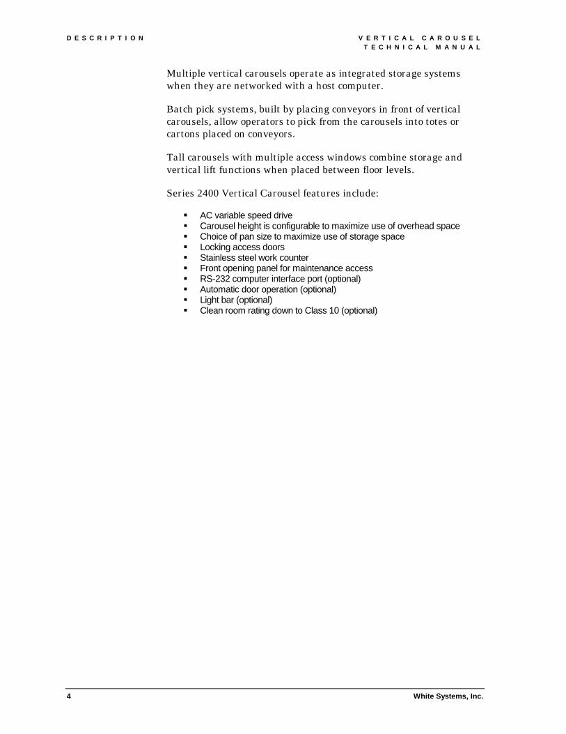
Multiple vertical carousels operate as integrated storage systems when they are networked with a host computer.
Batch pick systems, built by placing conveyors in front of vertical carousels, allow operators to pick from the carousels into totes or cartons placed on conveyors.
Tall carousels with multiple access windows combine storage and vertical lift functions when placed between floor levels.
Series 2400 Vertical Carousel features include:
!" AC variable speed drive !" Carousel height is configurable to maximize use of overhead space !" Choice of pan size to maximize use of storage space !" Locking access doors !" Stainless steel work counter !" Front opening panel for maintenance access !" RS-232 computer interface port (optional) !" Automatic door operation (optional) !" Light bar (optional) !" Clean room rating down to Class 10 (optional)

V E R T I C A L C A R O U S E L D E S C R I P T I O N T E C H N I C A L M A N U A L
White Systems, Inc. 5
B
A
C D
E
F
G
2.2 OPERATING CONTROLS 2.2.1 Location of operating controls 2 . 2 . 1 . 1 E M E R G E N C Y S T O P B U T T O N S
Three emergency stop buttons are provided at every door opening; one at each side of the opening, and one in the Carousel Interface Terminal.
2 . 2 . 1 . 2 C A R O U S E L I N T E R F A C E T E R M I N A L
The Carousel Interface Terminal is located above the door opening at the center of the unit. Up to four terminals can be accommodated on one carousel.
2.2.2 Carousel Interface Terminal The controls on the Carousel Interface Terminal have the following functions (see Figure 2).
A. EMERGENCY STOP: Red mushroom pushbutton; stops and prevents pan rotation. This switch must be reset before carousel operation can resume.
PIEZOELECTRIC TONE ALARM (alternate): Audible signal indicates operational status of carousel.
Figure 2. CONTROLS AND INDICATORS
D E S C R I P T I O N V E R T I C A L C A R O U S E L T E C H N I C A L M A N U A L
6 White Systems, Inc.
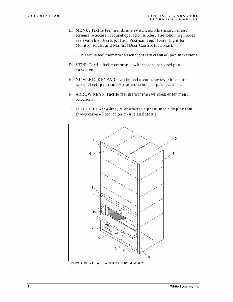
B. MENU: Tactile feel membrane switch; scrolls through menu screens to access carousel operation modes. The following modes are available: Startup, Host, Position, Jog, Home, Light bar Monitor, Fault, and Manual Door Control (optional).
C. GO: Tactile feel membrane switch; starts carousel pan movement.
D. STOP: Tactile feel membrane switch; stops carousel pan movement.
E. NUMERIC KEYPAD: Tactile feel membrane switches; enter carousel setup parameters and destination pan locations.
F. ARROW KEYS: Tactile feel membrane switches; enter menu selections.
G. LCD DISPLAY: 4-line, 20-character alphanumeric display that shows carousel operation menus and status.
Figure 3. VERTICAL CAROUSEL ASSEMBLY
H
I J
E
K
N
O
A L
B
C
G
F
F
D

V E R T I C A L C A R O U S E L D E S C R I P T I O N T E C H N I C A L M A N U A L
White Systems, Inc. 7
2.3 THEORY OF OPERATION The Series 2400 Vertical Carousel consists of a set of horizontal pans that travel in a vertical closed-loop track inside a metal enclosure. Pans are accessed through a door at the front of the unit.
To operate the vertical carousel, an operator selects a numbered pan location. The machine moves the pan to the door opening. If the unit is equipped with a light bar, a light on the counter top will indicate the selected pan compartment. The operator then loads or unloads material from the pan. When the transaction is complete and the door opening is clear, the operator is free to select another pan location.
The machine consists of three subassemblies: enclosure, conveying mechanism, and controls.
2.3.1 Enclosure The enclosure (see Figure 3) is made up of modular, bolt-together steel panels (F).
An opening at the front allows access to the pans (H). Two sliding doors (A) retract into the top and bottom of the opening. When the doors are open, pressing the upper or lower edges will stop pan rotation. When closed, the doors can be locked to secure the contents of the pans.
A stainless steel work counter (B) attaches below the opening.
A removable access panel (C) attaches to the front of the unit below the counter. The panel provides access to the drive assembly (N) and electrical enclosure (O) for maintenance and servicing.
A hinged supervisor's panel (I) and idle panel (L) open to allow access to cabling terminal blocks and drive motor.
Popular options include: fluorescent task lighting (E) over the work counter, RS-232 serial interface port (J) and courtesy outlet (K) on the left side of the opening, and a three-piece dust cover (D) that encloses the top of the unit.
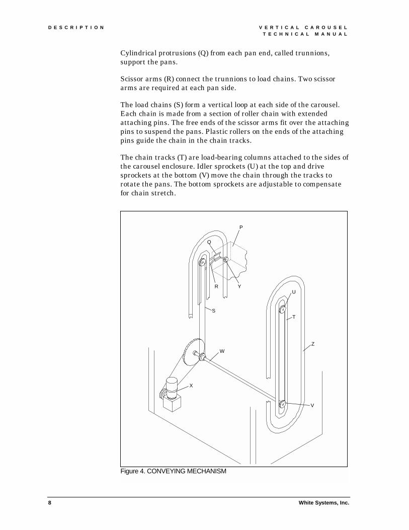
2.3.2 Conveying mechanism The conveying mechanism includes pans, trunnions, load chain, chain track, stabilizing track, and drive assembly (see Figure 4).
On single access carousels, each pan (P) has an open front. On double access carousels, the pans have an open front and back. The interior of the pan may be divided into compartments by horizontal shelves and vertical dividers to maximize use of storage space.
D E S C R I P T I O N V E R T I C A L C A R O U S E L T E C H N I C A L M A N U A L
8 White Systems, Inc.
Cylindrical protrusions (Q) from each pan end, called trunnions, support the pans.
Scissor arms (R) connect the trunnions to load chains. Two scissor arms are required at each pan side.
The load chains (S) form a vertical loop at each side of the carousel. Each chain is made from a section of roller chain with extended attaching pins. The free ends of the scissor arms fit over the attaching pins to suspend the pans. Plastic rollers on the ends of the attaching pins guide the chain in the chain tracks.
The chain tracks (T) are load-bearing columns attached to the sides of the carousel enclosure. Idler sprockets (U) at the top and drive sprockets at the bottom (V) move the chain through the tracks to rotate the pans. The bottom sprockets are adjustable to compensate for chain stretch.
Figure 4. CONVEYING MECHANISM
P
R Y
Q
S T
U
Z
V
W
X
V E R T I C A L C A R O U S E L D E S C R I P T I O N T E C H N I C A L M A N U A L
White Systems, Inc. 9
A torque shaft (W) connects the left and right drive sprockets to the drive assembly.
The drive assembly (X) is made up of an AC gear motor with an integral brake. The vector duty motor operates on three-phase AC. The electric brake is spring set – solenoid release and has a manual override. Output from the reducer is coupled through sprockets and roller chain to the torque shaft. An emergency hand crank attaches to the motor shaft. It allows personnel to rotate the pans in the event of a power failure.
Stabilizer arms (Y) attached to the trunnions keep the pans correctly oriented throughout their travel. Nylon rollers at the ends of the arms ride in the stabilizer tracks.
The stabilizer tracks (Z) are oval tracks attached to the sides of the carousel enclosure. The bottom curved sections of track are adjustable to compensate for chain stretch.
2.3.3 Controls The controls include a carousel interface terminal, sensors, electrical enclosure, programmable microprocessor control, motor drive, wire harness, and optional light bar.
2 . 3 . 3 . 1 C A R O U S E L I N T E R F A C E T E R M I N A L
An enclosure containing a membrane keypad with tactile feedback and a LCD display is mounted at the center of the carousel, above the door opening. The 20-character, 4-line display is backlit for increased visibility. All carousel setup parameters, operation commands, and status messages are available through a series of menu selections.
2 . 3 . 3 . 2 R S - 2 3 2 S E R I A L I N T E R F A C E P O R T ( O P T I O N A L )
This port allows a host computer to control pan motion and monitor system status. The female DB9 connector located at the left side of the door opening will accept asynchronous, point-to-point, ASCII communications up to 9600 baud.
2 . 3 . 3 . 3 S E N S O R S A N D S W I T C H E S
The following devices will trigger an emergency stop and prevent pan rotation: emergency stop buttons, door limit switch (touch bar), lower access panel limit switch, supervisor's panel limit switch, door opening upper photo eye, door opening lower photo eye, and motor overload. During an emergency stop, the motor drive is isolated from power by the MC1 relay. After an emergency stop, the control will require a manual reset before normal operation of the carousel can resume.

D E S C R I P T I O N V E R T I C A L C A R O U S E L T E C H N I C A L M A N U A L
10 White Systems, Inc.
An optical reference sensor and 128 pulse per revolution encoder provide signals to the microprocessor controller for pan movement. All devices operate at 12V DC.
2 . 3 . 3 . 4 E L E C T R I C A L E N C L O S U R E
A NEMA 1 enclosure, located at the base of the carousel behind the lower access panel, houses the control system components (see Figure 5). A lockable power disconnect switch is located on the left side of the enclosure. Components located inside the enclosure include: programmable microprocessor controller, I/O boards, motor drive, power supply, fuses, and terminal blocks. The control package is rated for operation in ambient temperatures of 33° to 104°F.
2 . 3 . 3 . 5 P R O G R A M M A B L E M I C R O P R O C E S S O R C O N T R O L L E R
The controller is based on a high performance, 32 bit, low power single board computer. Onboard memory consists of ROM, flash RAM, and battery backed RAM. Other features include onboard real time clock, and watchdog timer. The single board computer receives operator keypad inputs, sends LCD messages, monitors sensor inputs, controls pan movement, and communicates with the host computer. The unit supports up to four Carousel Interface Terminals.
2 . 3 . 3 . 6 M O T O R D R I V E
A modular, 230V AC motor drive, powers the AC gear motor. The drive uses an advanced sensorless flux-vector control system with 4-quadrant speed and torque control. It offers 250% starting torque, .2% speed regulation and 1.5 msec torque loop response. The drive
Figure 5. ELECTRICAL ENCLOSURE
V E R T I C A L C A R O U S E L D E S C R I P T I O N T E C H N I C A L M A N U A L
White Systems, Inc. 11
operates on 200 to 230V AC, three-phase power. It is capable of running on 120V single-phase power (derated output) in an emergency. A built-in RS-485 serial communications port can be used as a diagnostic tool to configure drive parameters, operate the drive, and measure system parameters.
2 . 3 . 3 . 7 W I R E H A R N E S S
The Carousel Interface Terminal, sensors, and switches for at door opening connect to two 8-port terminal blocks with twist-lock plugs. The terminal blocks, located behind the supervisor's panel and idle side panel, connect by cables and twist-lock plugs to the electrical enclosure.
2 . 3 . 3 . 8 L I G H T B A R ( O P T I O N A L )
Two styles of light bars are available. The first type illuminates a LED on the counter top to indicate the selected pick location. The second type is an intelligent device that uses an alphanumeric display and "task complete" button to show pick information.
I N S T A L L A T I O N V E R T I C A L C A R O U S E L T E C H N I C A L M A N U A L
12 White Systems, Inc.
3. INSTALLATION The following instructions are intended for all carousel models. Special instructions for optional equipment are located in Section 7.
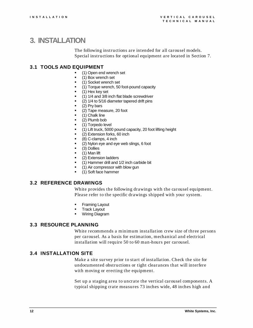
3.1 TOOLS AND EQUIPMENT !" (1) Open end wrench set !" (1) Box wrench set !" (1) Socket wrench set !" (1) Torque wrench, 50 foot-pound capacity !" (1) Hex key set !" (1) 1/4 and 3/8 inch flat blade screwdriver !" (2) 1/4 to 5/16 diameter tapered drift pins !" (2) Pry bars !" (2) Tape measure, 20 foot !" (1) Chalk line !" (2) Plumb bob !" (1) Torpedo level !" (1) Lift truck, 5000 pound capacity, 20 foot lifting height !" (2) Extension forks, 60 inch !" (8) C-clamps, 4 inch !" (2) Nylon eye and eye web slings, 6 foot !" (3) Dollies !" (1) Man lift !" (2) Extension ladders !" (1) Hammer drill and 1/2 inch carbide bit !" (1) Air compressor with blow gun !" (1) Soft face hammer
3.2 REFERENCE DRAWINGS
White provides the following drawings with the carousel equipment. Please refer to the specific drawings shipped with your system.
!" Framing Layout !" Track Layout !" Wiring Diagram
3.3 RESOURCE PLANNING White recommends a minimum installation crew size of three persons per carousel. As a basis for estimation, mechanical and electrical installation will require 50 to 60 man-hours per carousel.
3.4 INSTALLATION SITE Make a site survey prior to start of installation. Check the site for undocumented obstructions or tight clearances that will interfere with moving or erecting the equipment.
Set up a staging area to uncrate the vertical carousel components. A typical shipping crate measures 73 inches wide, 48 inches high and

V E R T I C A L C A R O U S E L I N S T A L L A T I O N T E C H N I C A L M A N U A L
White Systems, Inc. 13
up to 25 feet long. Pans, front and rear panels are shipped on separate skids.
3.5 UNCRATING 3.5.1 Inspection Before accepting shipment, you should check the crates for external damage. Open the crates and remove protective material from around the components. Check for damaged parts. Document any damage and have the receiving department issue a freight claim.
3.5.2 Itemized parts checklist Parts will be crated as follows:
COMPONENT LOCATION Right side upright (idler) Crate, top Left side upright (drive) Crate, bottom Counter Crate Access panel Crate Tie rods Crate Front and rear panels Skid Access doors Skid Pans Skid or box
Use the packing list located on crate number 1 to check that all components are present. If any parts are missing or damaged, notify White’s Customer One Protection, technical support group at 1-800-571-8822.

I N S T A L L A T I O N V E R T I C A L C A R O U S E L T E C H N I C A L M A N U A L
14
Fig
TIE RODS
CHAIN TRACK
TORQUE SHAFT
SPREADER
CROSSBAR
GEAR MOTOR
ELECTRICAL ENCLOSURE
White Systems, Inc.
ure 6. INTERNAL FRAMEWORK BOTTOM TIE ROD

V E R T I C A L C A R O U S E L I N S T A L L A T I O N T E C H N I C A L M A N U A L
White Systems, Inc. 15
3.6 ASSEMBLING THE CAROUSEL ENCLOSURE 3.6.1 Layout Accurate alignment of the carousel sides is critical to the operation of the unit. The following layout procedure will assist in placing the sides parallel and square to each other.
1. Determine the model and width of the carousel you are installing and use the following chart to determine the footprint.
MODEL PAN WIDTH MACHINE WIDTH
MACHINE DEPTH
DIAGONAL MEASUREMENT
2400 130 inches 154-1/2 inches 67-3/4 inches 168-11/16 inches 2400 112 inches 136-1/2 inches 67-3/4 inches 152-3/8 inches 2400 106 inches 130-1/2 inches 67-3/4 inches 147-1/32 inches 2400 100 inches 124-1/2 inches 67-3/4 inches 141-3/4 inches 2400 95 inches 119-1/2 inches 67-3/4 inches 137-3/8 inches 2400 72 inches 96-1/2 inches 67-3/4 inches 117-29/32 inches 2400 60 inches 84-1/2 inches 67-3/4 inches 108-5/16 inches 1800 130 inches 154-1/2 inches 56-1/4 inches 164-7/16 inches 1800 112 inches 136-1/2 inches 56-1/4 inches 147-5/8 inches 1800 106 inches 130-1/2 inches 56-1/4 inches 142-3/32 inches 1800 100 inches 124-1/2 inches 56-1/4 inches 136-5/8 inches 1800 95 inches 119-1/2 inches 56-1/4 inches 132-1/16 inches 1800 72 inches 96-1/2 inches 56-1/4 inches 111-11/16 inches 1800 60 inches 84-1/2 inches 56-1/4 inches 101-1/2 inches 1600 130 inches 154-1/2 inches 56-1/4 inches 164-7/16 inches 1600 112 inches 136-1/2 inches 56-1/4 inches 147-5/8 inches 1600 106 inches 130-1/2 inches 56-1/4 inches 142-3/32 inches 1600 100 inches 124-1/2 inches 56-1/4 inches 136-5/8 inches 1600 95 inches 119-1/2 inches 56-1/4 inches 132-1/16 inches 1600 72 inches 96-1/2 inches 56-1/4 inches 111-11/16 inches 1600 60 inches 84-1/2 inches 56-1/4 inches 101-1/2 inches 1500 130 inches 154-1/2 inches 56-1/4 inches 164-7/16 inches 1500 112 inches 136-1/2 inches 56-1/4 inches 147-5/8 inches 1500 106 inches 130-1/2 inches 56-1/4 inches 142-3/32 inches 1500 100 inches 124-1/2 inches 56-1/4 inches 136-5/8 inches 1500 95 inches 119-1/2 inches 56-1/4 inches 132-1/16 inches 1500 72 inches 96-1/2 inches 56-1/4 inches 111-11/16 inches 1500 60 inches 84-1/2 inches 56-1/4 inches 101-1/2 inches
2. Refer to the building floor plan; snap a chalk line to represent the front edge of the carousel.
3. Snap a chalk line perpendicular to the first line to represent the rear edge of the unit.
4. Mark the position of the four corners of the unit. Check the dimensions using the diagonal measurements from the footprint chart.

I N S T A L L A T I O N V E R T I C A L C A R O U S E L T E C H N I C A L M A N U A L
16 White Systems, Inc.
5. Snap a chalk line through each set of marks to represent the sides of the carousel.
3.6.2 Uncrating the carousel sides Vertical carousels are shipped with the right side assembly (idler side) at the top of the crate and the left side assembly (drive side) at the bottom of the crate. Both sides face up with the chain track exposed.
The drive side is the heaviest side and can weigh up to 3000 pounds. This section is the hardest to handle because its weight is concentrated in the lower front corner. Typically, the drive side is installed first.
1. Attach two slings, spaced 4 feet apart, at the center of the chain track (see Figure 7).
2. Position the forks of the lift truck above the slings. Slip the eyes of the slings over the forks.
Figure 7. UNCRATING SIDES
LIFT TRUCK CAROUSEL SIDE
C-CLAMP
NYLON SLING
CRATE

V E R T I C A L C A R O U S E L I N S T A L L A T I O N T E C H N I C A L M A N U A L
White Systems, Inc.
3. Lift the right side assembly out of the crate.
4. Move the side to the staging area and lower it onto two padded 4 x 4s. Position the 4 x 4s below the chain sprockets.
5. Remove the slings.
6. Attach a sling to the base frame of the left side.
7. Attach the second sling to the chain track at a point 4 to 5 feet away from the first sling.
8. Position the forks of the lift truck above the slings. Slip the eyes of the slings over the forks.
TO PREVENT THE SLINGS FROM SLIPPING OFF, FASTEN C-CLAMPS TO THE FORK ENDS AND TILT THE MAST BACKWARD BEFORE LIFTING THE SIDE.
BOTTOM
DOLLY (WITH CARDBOARD)
MOTOR-GEARBOX (LEFT SIDE)
17
9. Lift the left side assembly out of the crate.
10. Lower the side onto two padded dollies. Position the dollies below the chain sprockets (see Figure 8).
Figure 8. TRANSPORTING SIDES
TOP DOLLY (WITH CARDBOARD)
VIEW B ACCEPTABLE POSITION
VIEW B ACCEPTABLE POSITION

I N S T A L L A T I O N V E R T I C A L C A R O U S E L T E C H N I C A L M A N U A L
18 White Systems, Inc.
11. Disconnect the slings.
NOTE: If the carousel side must be moved through a narrow opening, tilt the side and place its edge on the dollies. White recommends using drywall dollies to brace the side as it is moved.
3.6.3 Placing the left carousel side 1. Move the left side assembly to the front of the chalked layout
lines. Orient the side with the leveling feet on the right and the motor towards the front (see Figure 9).
2. Remove the four 3/8-16 hex head cap screws from each of the crossbar attachment points and save for later use.
3. Mark a lift point on the chain track 2/3 (minimum) of the distance from the leveling feet to the top of the side assembly.
4. Align the lift point with the chalked layout lines. Move the side to position the lift point approximately one foot to the right of the left side chalk line.
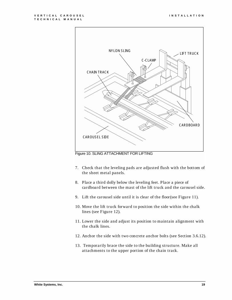
5. Attach a sling around the chain track at the lift point (see Figure 10).
6. Attach the sling to the left lift truck fork.
Figure 9. POSITIONING SIDE FOR LIFTING
LIFT POINT
TOP
DOLLY 12"
LEFT SIDE
CHALK LINES
H
2/3 H (MINIMUM)
LIFT TRUCK
LEFT CAROUSEL SIDE BASE
DOLLY
V E R T I C A L C A R O U S E L I N S T A L L A T I O N T E C H N I C A L M A N U A L
White Systems, Inc.
7. Check that the leveling pads are adjusted flush with the bottom of the sheet metal panels.
8. Place a third dolly below the leveling feet. Place a piece of cardboard between the mast of the lift truck and the carousel side.
9. Lift the carousel side until it is clear of the floor(see Figure 11).
Figure 10. SLING ATTACHMENT FOR LIFTING
LIFT TRUCK NYLON SLING
C-CLAMP
CAROUSEL SIDE
CARDBOARD
CHAIN TRACK
19
10. Move the lift truck forward to position the side within the chalk lines (see Figure 12).
11. Lower the side and adjust its position to maintain alignment with the chalk lines.
12. Anchor the side with two concrete anchor bolts (see Section 3.6.12).
13. Temporarily brace the side to the building structure. Make all attachments to the upper portion of the chain track.

I N S T A L L A T I O N V E R T I C A L C A R O U S E L T E C H N I C A L M A N U A L
20
3.6.4 Placing the right carousel side 1. Move the right side assembly to the front of the chalked layout
lines. Orient the side with the leveling feet on the left.
2. Remove the four 3/8-16 hex head cap screws from each of the crossbar attachment points and save for later use.
3. Mark a lift point on the chain track 2/3 (minimum) of the distance
4.
5.
6.
7.
8.
Figure 11. LIFTING THE SIDE
LIFT TRUCK
DOLLY
CARDBOARD
RIGHT CAROUSEL SIDE
LIFT POINT
White Systems, Inc.
from the leveling feet to the top of the side assembly.
Align the lift point with the chalked layout lines. Move the side to position the lift point approximately one foot to the left of the right side chalk line.
Attach a sling around the chain track at the lift point.
Attach the sling to the right lift truck fork.
Check that the leveling pads are adjusted flush with the bottom of the sheet metal panels.
Place a third dolly below the leveling feet. Place a piece of cardboard between the mast of the lift truck and the carousel side.

V E R T I C A L C A R O U S E L I N S T A L L A T I O N T E C H N I C A L M A N U A L
White Systems, Inc. 21
9. Lift the carousel side until it is clear of the floor.
10. Move the lift truck forward to position the side within the chalk lines.
11. Lower the side and adjust its position to maintain alignment with the chalk lines.
12. Use the lift truck to support the side until you install the crossbars.
3.6.5 Installing the crossbars First, install the center crossbar. Next, add the lower crossbars sequentially towards the bottom. Finally, add the upper crossbars sequentially towards the top.
1. Hoist a crossbar into position. Use a drift pin to align the holes in the flanges with the threaded holes in the chain track (see Figure 13).
2. Secure with four 3/8-16 x 1 inch Grade 8 bolts, lock washers, and flat washers on each end. Do not tighten.
3. Repeat steps 1 and 2 at each attachment point.
Figure 12. POSITIONING THE SIDE
C-CLAMP
NYLON SLING
INSTALLATION SITE CHALK LINES
LIFT TRUCK

I N S T A L L A T I O N V E R T I C A L C A R O U S E L T E C H N I C A L M A N U A L
22 White Systems, Inc.
3.6.6 Installing the torque shaft The torque shaft couples the left and right side drive sprockets. The position of sprockets must be synchronized to keep the pans level. Painted alignment marks on the chains, sprockets and torque shaft will be used to synchronize the left and right sides of the carousel.
Figure 13. CROSSBAR ATTACHMENT
Figure 14. LOWER END OF CHAIN TRACK
CROSSBAR ATTACHMENT PLATE
DRIVE SPROCKET
GUIDE PLATE
LOWER END OF CHAIN TRACK
CHAIN TRACK
FLAT WASHER
LOCKWASHER
BOLT
CROSSBAR
V E R T I C A L C A R O U S E L I N S T A L L A T I O N T E C H N I C A L M A N U A L
White Systems, Inc. 23
1. Remove six 1/2-13 x 1-1/2 inch Grade 8 bolts from each drive sprocket. Set the hardware aside for later use (see Figure 14).
2. Remove eight flat head screws and star washers from each guide plate at the lower end of the chain tracks. Set the guide plates and hardware aside for later use.
3. Each side of the carousel has a trunnion plate marked with white paint. Locate the marked trunnion plates and move them to the bottom of the carousel.
4. Locate the painted links on the load chains next to the marked trunnion plates. Adjust the chains to align the painted links on the left and right drive sprockets (see Figure 15).
5. Lift the torque shaft into place between the drive sprockets.
6. Align the yellow paint mark on the left flange with the paint mark on the left sprocket. Use a drift pin to line up the holes in the flange with the threaded holes in the sprocket. Secure the shaft to the sprocket with six 1/2-13 x 1-1/2 inch Grade 8 bolts and lock washers. Do not tighten.
7. Align the yellow paint mark on the right flange with the paint mark on the right sprocket. Use a drift pin to line up the holes in the flange with the threaded holes in the sprocket. Secure the shaft to the sprocket with six 1/2-13 x 1-1/2 inch Grade 8 bolts and lock washers. Do not tighten.
8. Remove the shipping block supporting the large roller chain sprocket on the left side of the carousel. Tighten the torque shaft bolts to 60-70 foot-pounds.
9. Reinstall the guide plates to the lower ends of the chain tracks.

I N S T A L L A T I O N V E R T I C A L C A R O U S E L T E C H N I C A L M A N U A L
24 White Systems, Inc.
3.6.7 Installing the tie rods Consult framing layout drawing to identify tie rod locations.
1. Remove the slings and temporary bracing from the carousel.
2. Attach the top pair of tie rods to the carousel sides with four 5/16-18 x 3 inch hex head bolts, flat washers, and elastic stop nuts.
3. Attach two tie rods between each pair of crossbars. Secure the ends of the rods to the bracket holes with four 5/16-18 x 1-3/4 inch hex head bolts, flat washers, and elastic stop nuts.
4. Attach a set of tie rods to the brackets in the four corners of the lower support frame with four 5/16-18 x 1-3/4 inch hex head bolts, flat washers, and elastic stop nuts.
5. Leave the tie rods slack.
3.6.8 Installing the spreaders Four "L" shaped sheet metal spreaders connect the carousel sides at the upper and lower corners. The spreaders frame out the front and back openings for the skin panels (see Figure 16).
Figure 15. TORQUE SHAFT INSTALLATION
TORQUE SHAFT
PAINTED LINK
LOCKWASHER
SPROCKET
CHAIN TRACK
BOLT
RIGHT SIDE LEFT SIDE
V E R T I C A L C A R O U S E L I N S T A L L A T I O N T E C H N I C A L M A N U A L
White Systems, Inc. 25
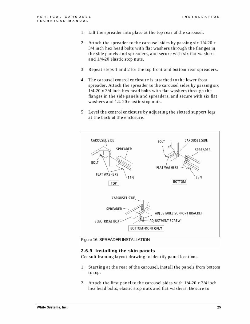
1. Lift the spreader into place at the top rear of the carousel.
2. Attach the spreader to the carousel sides by passing six 1/4-20 x 3/4 inch hex head bolts with flat washers through the flanges in the side panels and spreaders, and secure with six flat washers and 1/4-20 elastic stop nuts.
3. Repeat steps 1 and 2 for the top front and bottom rear spreaders.
4. The carousel control enclosure is attached to the lower front spreader. Attach the spreader to the carousel sides by passing six 1/4-20 x 3/4 inch hex head bolts with flat washers through the flanges in the side panels and spreaders, and secure with six flat washers and 1/4-20 elastic stop nuts.
5. Level the control enclosure by adjusting the slotted support legs at the back of the enclosure.
3.6.9 Installing the skin panels Consult framing layout drawing to identify panel locations.
1. Starting at the rear of the carousel, install the panels from bottom to top.
2. Attach the first panel to the carousel sides with 1/4-20 x 3/4 inch hex head bolts, elastic stop nuts and flat washers. Be sure to
Figure 16. SPREADER INSTALLATION
TOP BOTTOM
BOTTOM FRONT ONLY
CAROUSEL SIDE
SPREADER
ESN FLAT WASHERS
BOLT
CAROUSEL SIDE
SPREADER
ESN
FLAT WASHERS
BOLT
CAROUSEL SIDE
SPREADER
ELECTRICAL BOX ADJUSTMENT SCREW
ADJUSTABLE SUPPORT BRACKET

I N S T A L L A T I O N V E R T I C A L C A R O U S E L T E C H N I C A L M A N U A L
26
install a flat washer under the bolt head and the lock nut. Do not tighten (see Figure 17).
3. Stack the next panel on top of the first panel and secure to the carousel sides.
4. Join the panels by inserting 1/4-20 x 3/4 inch hex head bolts and flat washers through the bolt holes in the top and bottom flanges. Secure with flat washers and elastic stop nuts. Do not tighten.
5. Repeat steps 1 through 4 until the back of the unit is enclosed.
6. At the front of the unit, install the first panel above the door opening.
7. Attach the panel to the carousel sides with 1/4-20 x 3/4 inch hex head bolts, elastic stop nuts and flat washers. Be sure to install a flat washer under the bolt head and the lock nut. Do not tighten.
8. Stack the next panel on top of the first panel and secure to the carousel sides.
9. Join the panels by inserting 1/4-20 x 3/4 inch hex head bolts and flat washers through the bolt holes in the top and bottom flanges. Secure with flat washers and elastic stop nuts. Do not tighten.
10. Repeat steps 7 through 9 until the front of the unit is enclosed.
Fig
White Systems, Inc.
ure 17. PANEL INSTALLATION
CAROUSEL SIDE
PANEL
V E R T I C A L C A R O U S E L I N S T A L L A T I O N T E C H N I C A L M A N U A L
White Systems, Inc.
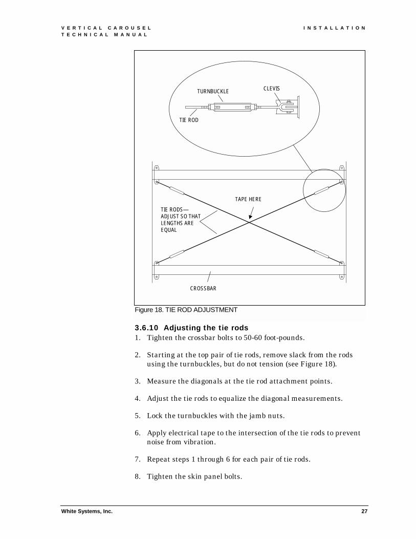
3.6.10 Adjusting the tie rods 1. Tighten the crossbar bolts to 50-60 foot-pounds.
Figure 18. TIE ROD ADJUSTMENT
TIE ROD
CLEVIS TURNBUCKLE
TAPE HERE
CROSSBAR
TIE RODS— ADJUST SO THAT LENGTHS ARE EQUAL
27
2. Starting at the top pair of tie rods, remove slack from the rods using the turnbuckles, but do not tension (see Figure 18).
3. Measure the diagonals at the tie rod attachment points.
4. Adjust the tie rods to equalize the diagonal measurements.
5. Lock the turnbuckles with the jamb nuts.
6. Apply electrical tape to the intersection of the tie rods to prevent noise from vibration.
7. Repeat steps 1 through 6 for each pair of tie rods.
8. Tighten the skin panel bolts.
I N S T A L L A T I O N V E R T I C A L C A R O U S E L T E C H N I C A L M A N U A L
28
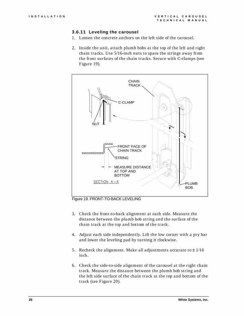
3.6.11 Leveling the carousel 1. Loosen the concrete anchors on the left side of the carousel.
2. Inside the unit, attach plumb bobs at the top of the left and right chain tracks. Use 5/16-inch nuts to space the strings away from the front surfaces of the chain tracks. Secure with C-clamps (see Figure 19).
3.
4.
5.
6.
Figure 19. FRONT-TO-BACK LEVELING
C-CLAMP
FRONT FACE OF CHAIN TRACK
MEASURE DISTANCE AT TOP AND BOTTOM
STRING
NUT
PLUMB BOB
CHAIN TRACK
White Systems, Inc.
Check the front-to-back alignment at each side. Measure the distance between the plumb bob string and the surface of the chain track at the top and bottom of the track.
Adjust each side independently. Lift the low corner with a pry bar and lower the leveling pad by turning it clockwise.
Recheck the alignment. Make all adjustments accurate to ± 1/16 inch.
Check the side-to-side alignment of the carousel at the right chain track. Measure the distance between the plumb bob string and the left side surface of the chain track at the top and bottom of the track (see Figure 20).

V E R T I C A L C A R O U S E L I N S T A L L A T I O N T E C H N I C A L M A N U A L
White Systems, Inc. 29
7. Adjust the low side of the carousel by lifting the side with a pry bar and lowering the front and back leveling pads an equal number of turns.
8. Recheck side-to-side alignment and front-to-back alignment. Make all adjustments accurate to ± 1/16 inch.
9. Adjust the two inner leveling pads on each side so that they contact the floor.
3.6.12 Anchoring the carousel Each carousel side has two anchoring clips bolted to the inside of the frame at the front and back of the unit. The anchoring clips have clearance holes for 1/2 inch anchor studs (see Figure 21).
1. Fill the gap between the bottom frame tubes and the floor slab with shims or non-shrink grout.
2. Adjust the anchoring clips to contact the floor slab.
3. Using a 1/2 inch diameter bit, drill through the anchoring clips into the floor slab to a depth of 3 inches.
Figure 20. SIDE-TO-SIDE LEVELING
MEASURE DISTANCE AT TOP AND BOTTOM
LEFT SIDE SURFACE

I N S T A L L A T I O N V E R T I C A L C A R O U S E L T E C H N I C A L M A N U A L
30 White Systems, Inc.
4. Blow the holes clean of dust fragments.
5. Insert an anchor into each hole.
6. Set the anchors with a soft face hammer.
7. Tighten the anchor nuts.
3.7 ELECTRO-MECHANICAL WIRING Refer to the wiring diagram shipped with the carousel for the correct connections.
3.7.1 Control enclosure 1. Attach the signal cables from the control enclosure to the terminal
blocks behind the supervisor's panel and the idle panel.
2. Check that the lockable disconnect switch is in the OFF position. Remove the enclosure cover.
Figure 21. CAROUSEL ANCHORING
V E R T I C A L C A R O U S E L I N S T A L L A T I O N T E C H N I C A L M A N U A L
White Systems, Inc. 31
3.7.2 Carousel Interface Terminal To install the Carousel Interface Terminal on the panel above the door opening:
1. Mount the standoff bracket to the terminal using four 10-32 screws, washers, and elastic stop nuts.
2. Pass the cable through the opening in the panel.
3. Attach the enclosure to the panel using four 10-32 screws, washers, and elastic stop nuts.
4. Route the cable to the right side terminal block and connect to the port indicated on the wiring diagram. Secure the cable with tie wraps to prevent contact with moving parts of the carousel mechanism.
3.7.3 Task light 1. Remove the task light mounting hardware from the panel above
the door opening.
2. Pass the power cable through the opening in the panel.
3. Attach the fluorescent light housing sections to the panel using the hardware removed in step 1.
4. Route the cable down the left side of the carousel to the control enclosure.
5. Connect the leads to terminals 11 and 12 on 1TB in the control enclosure.
3.7.4 Drive 1. Route the brake and motor cables from the drive junction box in
the left side of the carousel to the control enclosure.
2. Connect the green ground wire to the ground bus (next to 1TB).
3. Connect the motor leads to 1TB in the control enclosure. Connect the brown lead to terminal 1, the orange lead to terminal 2, and the yellow lead to terminal 3.
4. Connect the brake leads to terminals 4 and 5 on 1TB in the control enclosure.

A D J U S T M E N T S A N D S E T U P V E R T I C A L C A R O U S E L T E C H N I C A L M A N U A L
32 White Systems, Inc.
4. ADJUSTMENTS AND SETUP 4.1 ADJUSTING CONVEYING MECHANISM
4.1.1 Adjusting the load chains A take-up assembly, located at the bottom of each chain track, is used to pre-load the load chains. This adjustment prevents the chains from accumulating slack when the pans are installed and loaded.
1. Turn each take-up nut until the stop nut assembly bottoms out (see Figure 22).
2. Tighten the take-up nuts to 30 foot-pounds.
3. Check the position of the curved tracks by moving a trunnion assembly to the bottom of the drive sprockets. With the stabilizer wheel at the bottom of the track, the top of the trunnion plate should be level (see Figure 23).
4. If necessary, adjust the tracks by loosening the 3/8-16 attaching bolts. Move the tracks evenly to keep the gaps between the curved and straight sections equal at the front and back. Retighten the attaching bolts.
Figure 22. LOAD CHAIN ADJUSTMENT

V E R T I C A L C A R O U S E L A D J U S T M E N T S A N D S E T U P T E C H N I C A L M A N U A L
White Systems, Inc.
4.1.2 Adjusting the drive mechanism 1. Remove plugs A and B in the gear reducer (see Figure 24).
2. Check that the oil level reaches the bottom of the lower threaded hole. Add oil if necessary (see Section 6.4).
3. Install the vent plug in the top hole and the solid plug in the lower
Figure 23. CURVED TRACK ADJUSTMENT
STABILIZING ROLLER SHOULD NOT BE TIGHT AGAINST CURVED TRACK SIDE
TRUNNION PLATE SHOULD REMAIN LEVEL THROUGHOUT THE TRACK
33
hole.
4. Remove the wooden shipping blocks from behind the motor and drive sprocket.
5. Loosen the four bolts (C) on the gear reducer mounting plate.
6. Release the brake and rotate the motor to equalize the drive chain.
7. Loosen the jam nut on jack bolt (D) and tighten the bolt until drive chain deflection is one inch or less. Tighten the jam nut and mounting plate bolts.

A D J U S T M E N T S A N D S E T U P V E R T I C A L C A R O U S E L T E C H N I C A L M A N U A L
34 White Systems, Inc.
4.2 CONNECTING POWER 4.2.1 Power requirements The vertical carousel requires a 200V to 230V AC, 60Hz, three-phase, 30A source supplied by the customer. The system shall be grounded in accordance with Article 250 of the National Electrical Code.
4.2.2 Courtesy outlets The courtesy outlets require a 120V AC, 60Hz, single-phase, 20A source supplied by the customer. There is no overload protection provided inside the carousel.
4.2.3 Connecting power to the carousel 1. Check that disconnect switch 1DS in the electrical enclosure is in
the OFF position.
2. Connect power to terminals 1L1, 3L2, and 5L3 of the switch.
Figure 24. GEAR MOTOR ADJUSTMENTS
C
A
D
B GEAR REDUCER MOUNTING PLATE

V E R T I C A L C A R O U S E L A D J U S T M E N T S A N D S E T U P T E C H N I C A L M A N U A L
White Systems, Inc. 35
HAZARD OF ELECTRICAL SHOCK OR BURN. DO NOT STAND IN FRONT OF OPEN PANEL WHEN INITIALLY APPLYING POWER. CLOSE AND SECURE ALL ENCLOSURE DOORS BEFORE SWITCHING POWER ON AT THE DISCONNECT.
4.2.4 Powering the electrical enclosure 1. Check all field wiring and connectors before applying power to the
enclosure.
2. Close the cover of the electrical enclosure.
3. Turn the disconnect switch to the ON position. The LCD display should light on the Carousel Interface Terminal, indicating the presence of power in the panel (see Section 5.3 for carousel operation and configuration).
4.3 FINAL ASSEMBLY
POSSIBLE UNEXPECTED MACHINE OPERATION. BEFORE ATTEMPTING TO SERVICE OR ADJUST THE CAROUSEL MECHANISM, REMOVE ALL POWER TO THE CONTROL ENCLOSURE. INSTALL SAFETY LOCKOUT DEVICES TO ENSURE MECHANISM DOES NOT START UNEXPECTEDLY.
4.3.1 Installing the pans Install pans at the front of the carousel through the lower access opening. Alternate the placement of pans at the front and back of the unit. Avoid an imbalance greater than four pans. Do not install the last four pans to leave clearance for the doors and counter.
1. Turn the disconnect switch to the ON position. Check that personnel are clear of the carousel.
2. Have a helper press down the lower access panel interlock switch. Use the Carousel Interface Terminal to jog a trunnion assembly into position. The trunnion plate should be at least two inches above the electrical box at the front of the carousel.

A D J U S T M E N T S A N D S E T U P V E R T I C A L C A R O U S E L T E C H N I C A L M A N U A L
36 White Systems, Inc.
TO AVOID DAMAGING THE CURVED TRACKS, BE SURE THAT ALL STABILIZING ARM ROLLERS ARE IN THEIR TRACKS AND THAT THE TRUNNION PLATES REMAIN LEVEL WHEN JOGGING THE CAROUSEL DRIVE.
3. Lockout/Tagout power to the carousel.
4. Place two 2 x 4s across the bottom spreaders. Slide a pan over the 2 x 4s and align with the trunnion plates (see Figure 25).
5. Bolt the pan ends to the trunnion plates with five 5/16-18 x 1-1/2 inch hex socket head bolts, lock washers and flat washers on each side. Do not tighten.
6. Install lock nuts on the hex socket head bolts. Do not tighten.
7. Repeat steps 1 through 6 for the remaining pans. Do not install the last four pans until the doors and counter are in place.
Figure 25. PAN INSTALLATION
TRUNNION PLATE
PAN
2 X 4

V E R T I C A L C A R O U S E L A D J U S T M E N T S A N D S E T U P T E C H N I C A L M A N U A L
White Systems, Inc. 37
4.3.2 Installing the counter The position of the counter can be identified by three weld nuts on each carousel side below the door opening.
1. Lockout/Tagout power to the carousel.
2. Align the bolt holes in the counter with the weld nuts in the carousel sides (see Figure 26).
3. Bolt the counter to the carousel sides using six 5/16-18 x 1 inch hex head bolts and lock washers.
4.3.3 Installing the doors Two sliding doors close the pan access opening at the front of the carousel. The doors slide in a track attached to the side of the opening. Wire rope cables connect the upper and lower doors, causing them to move in unison. A latching mechanism in the upper door locks both doors in the closed position.
The door slide assemblies are installed at the factory. Angles with nylon glides slide in track channels attached to the carousel sides. The doors attach to the angles.
Figure 26. COUNTER INSTALLATION
CAROUSEL SIDE
WELD NUT
COUNTER
FRONT OF CAROUSEL
A D J U S T M E N T S A N D S E T U P V E R T I C A L C A R O U S E L T E C H N I C A L M A N U A L
38 White Systems, Inc.
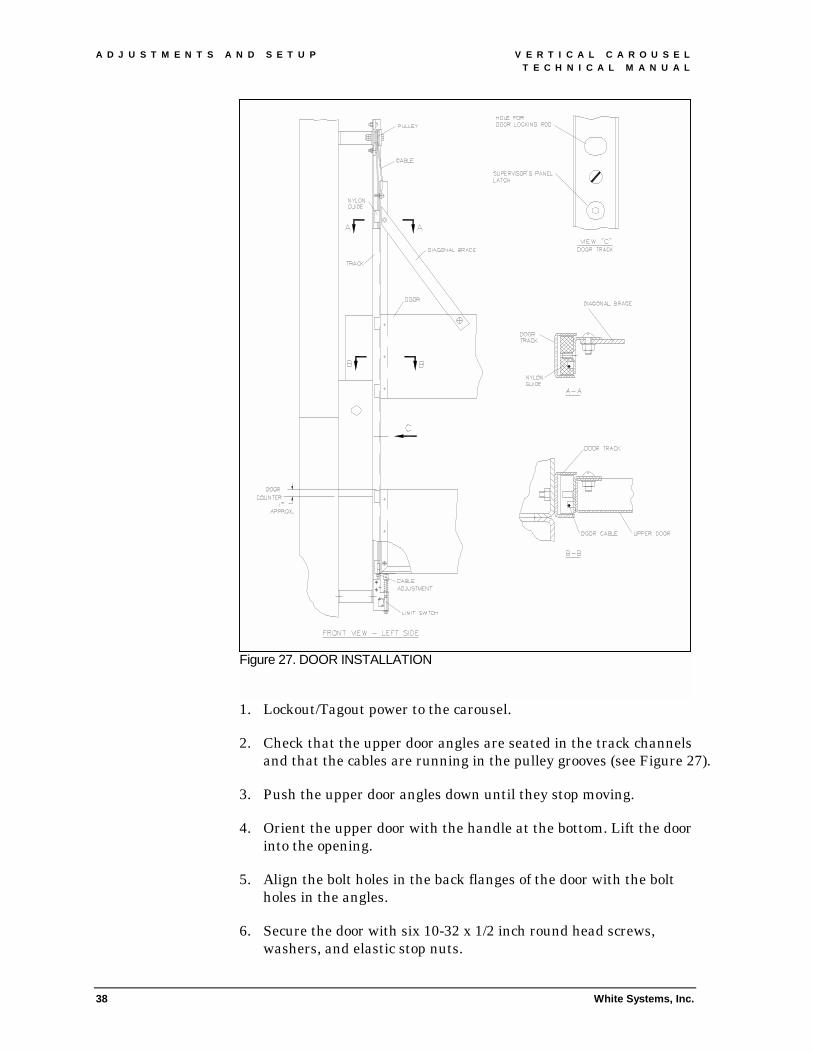
1. Lockout/Tagout power to the carousel.
2. Check that the upper door angles are seated in the track channels and that the cables are running in the pulley grooves (see Figure 27).
3. Push the upper door angles down until they stop moving.
4. Orient the upper door with the handle at the bottom. Lift the door into the opening.
5. Align the bolt holes in the back flanges of the door with the bolt holes in the angles.
6. Secure the door with six 10-32 x 1/2 inch round head screws, washers, and elastic stop nuts.
Figure 27. DOOR INSTALLATION

V E R T I C A L C A R O U S E L A D J U S T M E N T S A N D S E T U P T E C H N I C A L M A N U A L
White Systems, Inc. 39
7. Attach the diagonal braces to the top of the door with two 10-32 x 1/2 inch round head screws, washers, and elastic stop nuts.
8. Check that the lower door angles are seated in the track channels.
9. Lift the lower door into the opening and rest it on the limit switches.
10. Align the bolt holes in the back flanges of the door with the bolt holes in the angles.
11. Secure the door with six 10-32 x 1/2 inch round head screws, washers, and elastic stop nuts.
12. Test the cable adjustment by closing the doors and turning the locking handle. If the lock rods do not align with the sockets in the door track, the cables must be readjusted.
13. Make all adjustments to the cable anchors in the bottom nylon glides of the lower door. If the top door moves too far down, shorten the cables. If the top door doesn't move down far enough, loosen the cables. Adjust both cables equally to keep the door edges parallel.
14. With the cables adjusted correctly, the locking mechanism should work smoothly and the doors should fit together tightly. When the doors are open, the lower door should extend approximately one inch above the top of the counter.
15. For carousels equipped with 130-inch wide pans: Thread the stabilizing cables diagonally between the pulleys at the top of the doors (see Figure 28). Anchor the free ends of the cables with 10-32 x 1/2 inch round head screws, washers, and elastic stop nuts. Set cable tension to allow the doors to move smooth and parallel.

A D J U S T M E N T S A N D S E T U P V E R T I C A L C A R O U S E L T E C H N I C A L M A N U A L
40 White Systems, Inc.
4.3.4 Installing the last four pans Install the remaining pans as described in Section 4.3.1.
NOTE: If the pan height exceeds the height of the lower access opening, install the pans through the door opening.
4.3.5 Leveling the pans 1. Turn the disconnect switch to the ON position. Check that
personnel are clear of the carousel.
2. Have a helper press down the lower access panel interlock switch. Use the Carousel Interface Terminal to jog a pan into the door opening.
Figure 28. DOOR INSTALLATION (130-INCH WIDE PANS)
V E R T I C A L C A R O U S E L A D J U S T M E N T S A N D S E T U P T E C H N I C A L M A N U A L
White Systems, Inc. 41
3. Lockout/Tagout power to the carousel.
4. Check that all fastening bolts in the pan ends are loose.
5. Align the stabilizer rollers by pushing the front edge of the pan back and pulling it forward.
6. Place a torpedo level in the pan.
7. Slowly move the front edge down until the pan is level.
8. Tighten the bolts in the pan ends.
9. Check that the stabilizing rollers are aligned by rocking the pan front to back. If there is no play, repeat steps 4 through 8.
10. Move the pan to the lower access opening and tighten the jam nuts against the trunnion plates.
11. Apply self-adhesive pan numbers (see Figure 32 for numbering sequence).
12. Repeat steps 1 through 11 for each pan.
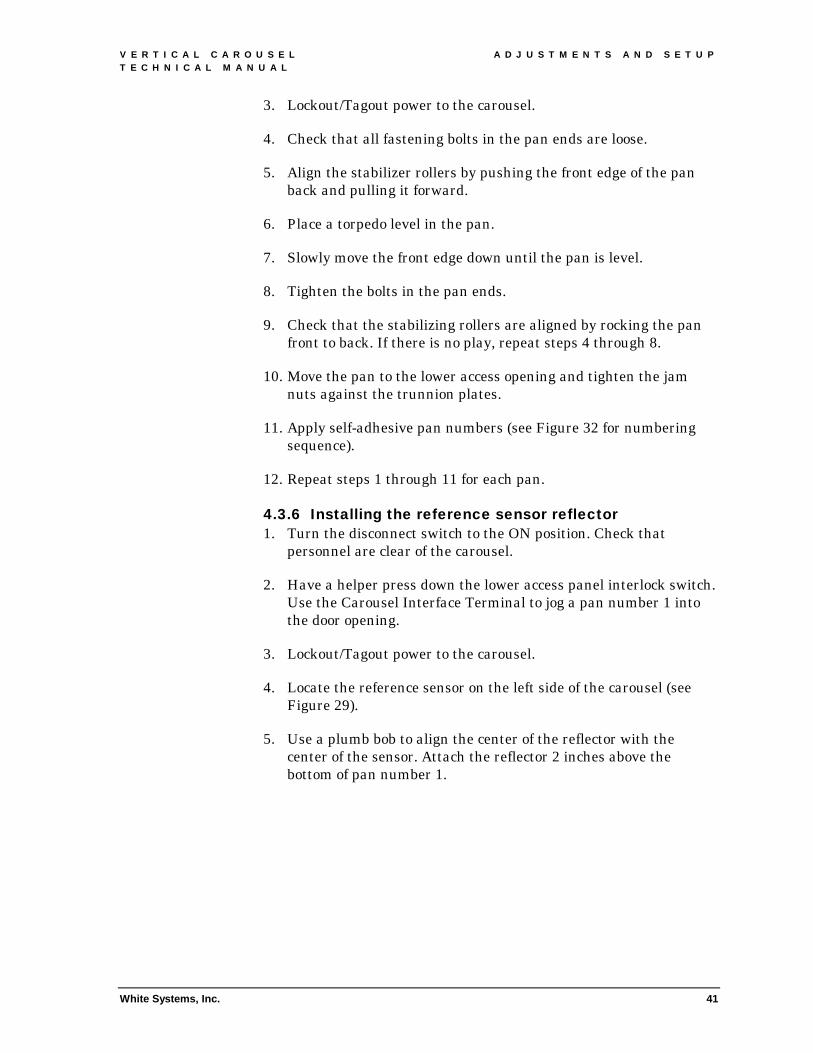
4.3.6 Installing the reference sensor reflector 1. Turn the disconnect switch to the ON position. Check that
personnel are clear of the carousel.
2. Have a helper press down the lower access panel interlock switch. Use the Carousel Interface Terminal to jog a pan number 1 into the door opening.
3. Lockout/Tagout power to the carousel.
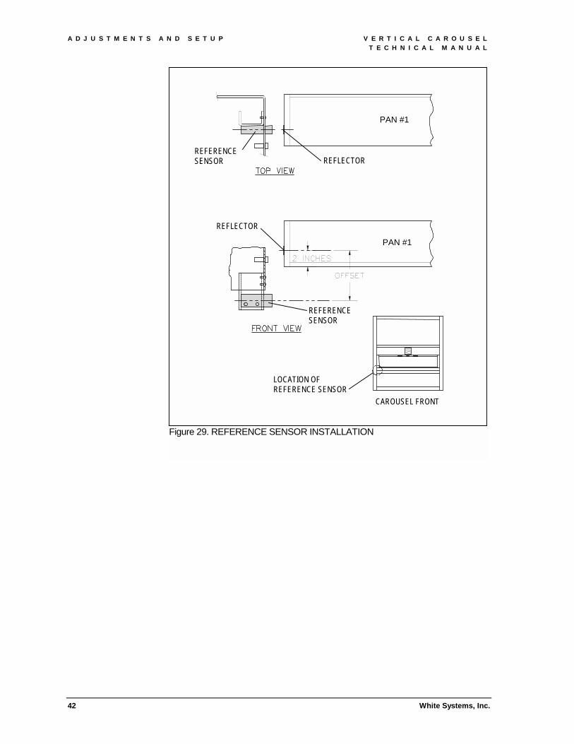
4. Locate the reference sensor on the left side of the carousel (see Figure 29).
5. Use a plumb bob to align the center of the reflector with the center of the sensor. Attach the reflector 2 inches above the bottom of pan number 1.
A D J U S T M E N T S A N D S E T U P V E R T I C A L C A R O U S E L T E C H N I C A L M A N U A L
42 White Systems, Inc.
Figure 29. REFERENCE SENSOR INSTALLATION
PAN #1
PAN #1
REFLECTOR
REFLECTOR
REFERENCE SENSOR
REFERENCE SENSOR
CAROUSEL FRONT
LOCATION OF REFERENCE SENSOR

V E R T I C A L C A R O U S E L A D J U S T M E N T S A N D S E T U P T E C H N I C A L M A N U A L
White Systems, Inc. 43
4.3.7 Installing the lower access panel 1. Orient the panel with the key locks at the top (see Figure 30).
2. Hook the slots in the bottom of the panel over the studs at the bottom of the access opening.
3. Close the panel and turn the key locks to secure.
Figure 30. ACCESS PANEL INSTALLATION
KEY LOCK
ACCESS PANEL
PIVOT PIN
SLOT
A D J U S T M E N T S A N D S E T U P V E R T I C A L C A R O U S E L T E C H N I C A L M A N U A L
44 White Systems, Inc.
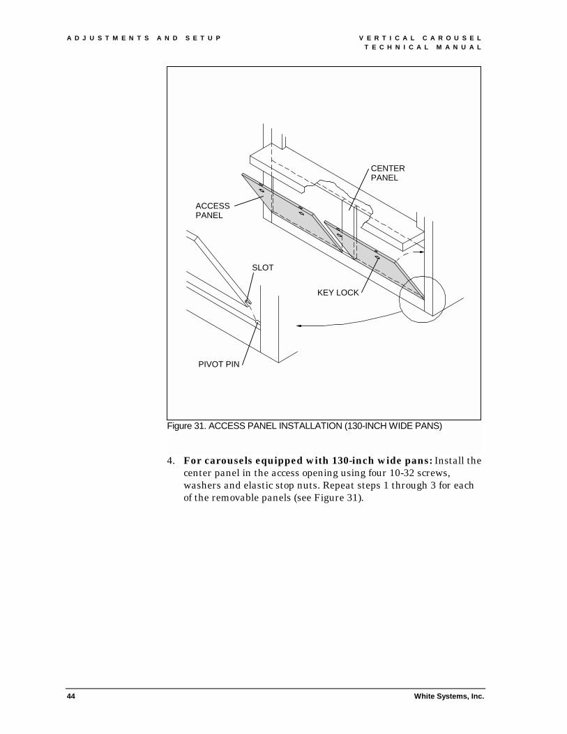
4. For carousels equipped with 130-inch wide pans: Install the center panel in the access opening using four 10-32 screws, washers and elastic stop nuts. Repeat steps 1 through 3 for each of the removable panels (see Figure 31).
Figure 31. ACCESS PANEL INSTALLATION (130-INCH WIDE PANS)
CENTER PANEL
ACCESS PANEL
SLOT
PIVOT PIN
KEY LOCK

V E R T I C A L C A R O U S E L O P E R A T I O N T E C H N I C A L M A N U A L
White Systems, Inc. 45
5. OPERATION 5.1 RULES FOR SAFE OPERATION
1. The Employer shall only permit trained personnel to operate the equipment.
2. Operators shall keep access areas open and free of obstructions.
3. Never climb, step, sit, ride or stand on the carousel pans.
4. Supervisors shall instruct personnel working on or near the equipment about the location and operation of safety and stopping devices.
5. The operator shall determine the cause of an emergency stop or system fault before restarting a carousel.
6. Personnel shall use the equipment to carry material it can handle safely. Never store oversize or overweight containers.
7. Only authorized personnel should try to correct a malfunction. The operator should immediately alert a supervisor if there is a problem with the carousel.
8. Equipment shall only be operated with all overload devices, guards and safety devices in place and operable.
5.2 LOADING THE CAROUSEL 5.2.1 Pan weight capacity The maximum weight capacity of the carousel pans is indicated by the fifth digit of the carousel model number; A "6" indicates a 600 pound live load capacity, and an "8" indicates a 800 pound capacity.
5.2.2 Carousel weight capacity The maximum weight capacity of the carousel is 25,000 pounds as listed on the serial number tag attached to the left side of the carousel.
5.2.3 Loading method When loading the carousel use an alternating front to back sequence (see Figure 32). On carousels with 3HP drives, do not exceed a 1,800-pound imbalance between the front and back pans of carousel. On carousels with 5HP drives, the maximum imbalance is 3,000 pounds.

O P E R A T I O N V E R T I C A L C A R O U S E L T E C H N I C A L M A N U A L
46 White Systems, Inc.
Load the pans in the following order: 1, 8, 7, 14, 13, 6, 5, 12, 11, 4, 3, 10, 9, and 2.
Figure 32. PAN LOADING
V E R T I C A L C A R O U S E L O P E R A T I O N T E C H N I C A L M A N U A L
White Systems, Inc. 47
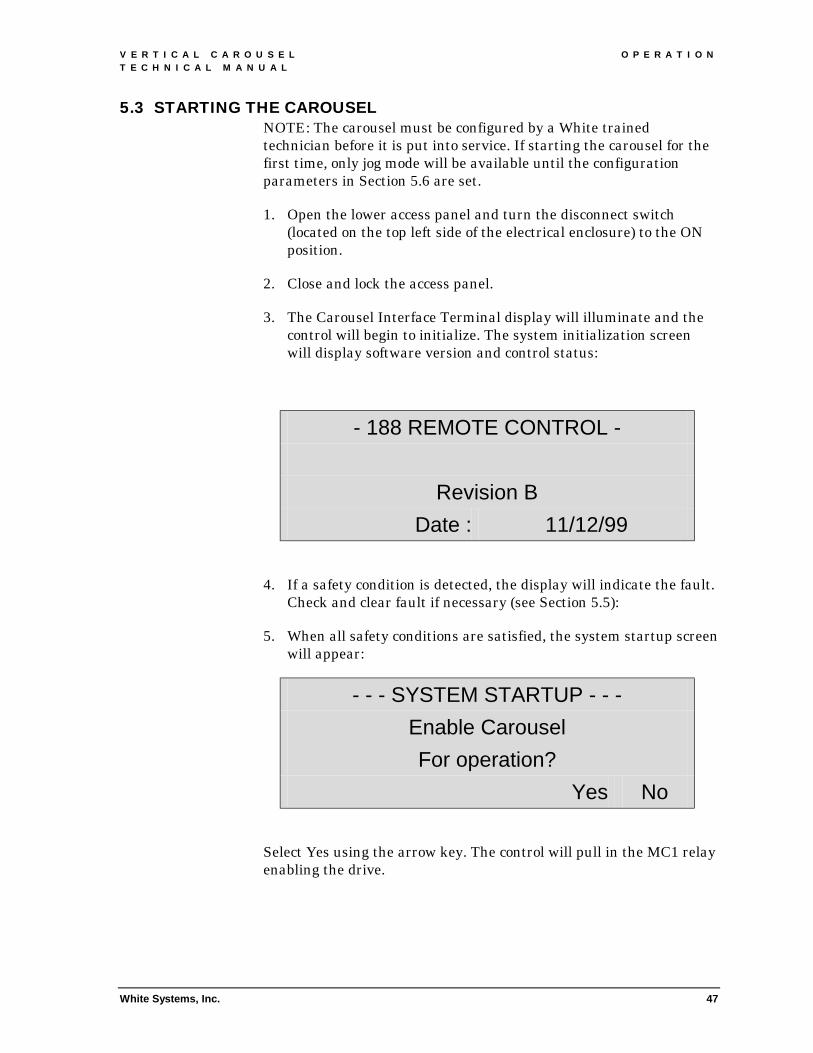
5.3 STARTING THE CAROUSEL NOTE: The carousel must be configured by a White trained technician before it is put into service. If starting the carousel for the first time, only jog mode will be available until the configuration parameters in Section 5.6 are set.
1. Open the lower access panel and turn the disconnect switch (located on the top left side of the electrical enclosure) to the ON position.
2. Close and lock the access panel.
3. The Carousel Interface Terminal display will illuminate and the control will begin to initialize. The system initialization screen will display software version and control status:
- 188 REMOTE CONTROL -
Revision B Date : 11/12/99
4. If a safety condition is detected, the display will indicate the fault. Check and clear fault if necessary (see Section 5.5):
5. When all safety conditions are satisfied, the system startup screen will appear:
- - - SYSTEM STARTUP - - - Enable Carousel For operation?
Yes No
Select Yes using the arrow key. The control will pull in the MC1 relay enabling the drive.

O P E R A T I O N V E R T I C A L C A R O U S E L T E C H N I C A L M A N U A L
48 White Systems, Inc.
When the carousel is enabled, the local control mode screen will appear:
- LOCAL CONTROL MODE - Press Menu button
to advance Host
Select Host Computer Mode with the arrow key or use the Menu key to scroll through the operating mode menus.
5.4 OPERATING MODES 5.4.1 Host computer mode The Host Computer screen shows the current pan position and the destination pan position for the next pick in the queue.
- HOST COMPUTER MODE - >> <<
[Position] [Destination] Clr Done
Return to Local Control Mode by selecting Done with the right arrow key.
5.4.2 Position carousel The Position Carousel screen allows the operator to enter a destination pan number and shows the current pan position. The default carousel ID number is 1 for carousel controls that are not networked.
- POSITION CAROUSEL - - Carousel ID# : 1
Target Pan# : [Position] Clr

V E R T I C A L C A R O U S E L O P E R A T I O N T E C H N I C A L M A N U A L
White Systems, Inc. 49
Enter a pan number and press GO to move the pan to the opening. Select Clr with the right arrow key to clear an entry. Press the MENU key to switch to a different operating mode.
5.4.3 Jog/move carousel The Jog/Move Carousel screen allows the operator to jog the carousel pans up or down. The default carousel ID number is 1 for carousel controls that are not networked.
- JOG/MOVE CAROUSEL - - Carousel ID# : 1
Select : Up Dn
Select Up or Dn with the arrow keys and press the GO key to move the carousel pans. Press the MENU key to switch to a different operating mode.
5.4.4 Home carousel The Home Carousel screen allows the operator to initiate an automatic routine to synchronize the pan positions with the door opening. The default carousel ID number is 1 for carousel controls that are not networked.
- - - HOME CAROUSEL - - - - Carousel ID# : 1
Home
Select Home with the left arrow key to initiate the routine. Press the MENU key to switch to a different operating mode.

O P E R A T I O N V E R T I C A L C A R O U S E L T E C H N I C A L M A N U A L
50 White Systems, Inc.
5.4.5 Lightbar monitor (optional) The Lightbar Monitor screen is a diagnostic tool that allows the operator to monitor communications between the host computer and the lightbar.
- - LIGHTBAR MONITOR - - >> <<
Clr Test
Select Test with the right arrow key to view the message stream. Press the MENU key to switch to a different operating mode.
5.4.6 Door control (optional) The Door Control screen allows the operator to manually open and close the automatic doors.
- - - - DOOR CONTROL - - - - Manual control of
Access door… Open Close
Select Open or Close with the arrow keys to actuate the doors. Press the MENU key to switch to a different operating mode.
5.5 FAULTS 5.5.1 Emergency stop fault The Safety screens indicate that an Emergency Stop switch is activated or an access panel is open, preventing pan rotation.
* * SAFETY - LEFT SIDE * * Main opening E-stop
or access panel! Clear

V E R T I C A L C A R O U S E L O P E R A T I O N T E C H N I C A L M A N U A L
White Systems, Inc. 51
Reset the indicated Emergency Stop switch or panel. Select Clear with the left arrow key to clear the screen.
5.5.2 Light curtain/touch bar fault The Safety Condition screens indicate that the light curtain is interrupted or touch bar is activated at the door opening, preventing pan rotation.
* * SAFETY CONDITION * * Check Main Opening Lt. Curtain/touchbar
Clear
Clear the indicated door opening. Select Clear with the left arrow key to clear the screen.
5.5.3 Execution fault The Cannot Execute screens indicate that a move command cannot be acted on for one of the following reasons: the door is open (optional), the carousel is disabled because of a fault condition, or a previous move is in process.
* * * CANNOT EXECUTE * * * Main opening Door is open
Clear
Correct the indicated fault. Select Clear with the left arrow key to clear the screen.

O P E R A T I O N V E R T I C A L C A R O U S E L T E C H N I C A L M A N U A L
52 White Systems, Inc.
5.5.4 Photo eye fault The Photoeye Blocked screen indicates that a photo eye beam is interrupted in the door opening, preventing pan rotation.
* * PHOTOEYE BLOCKED * * Check photoeye at
Main opening Clear
Clear the indicated photo eye. Select Clear with the left arrow key to clear the screen.
5.5.5 Imbalance fault The Drive Warning screen indicates that an excessive load imbalance has caused the carousel drive to shut down.
* * * * DRIVE WARNING * * * * Load imbalance
Detected! Clear
Select Clear with the left arrow key to clear the screen. Select Jog Mode and manually redistribute contents of pans to equalize load.
5.6 SETUP PARAMETERS 5.6.1 Password Use the MENU key to select the Setup Parameters screen.
- - SETUP PARAMETERS - - Enter 4 digit
Password : Clr Del
Enter the four-digit password to access and change system parameters.

V E R T I C A L C A R O U S E L O P E R A T I O N T E C H N I C A L M A N U A L
White Systems, Inc. 53
5.6.2 Set parameters The operator is prompted whether to restore default settings or enter new settings.
- - SETUP PARAMETERS - - Restore default
Settings? No Yes No
Select Yes or No with arrow keys. Default selection is No. Press MENU key to continue.
5.6.3 Checksums The operator is prompted whether to use checksums.
- - SETUP PARAMETERS - - Message checksums
Required? No Yes No
Select Yes or No with arrow keys. Default selection is No. Press MENU key to continue.
5.6.4 Pulses per revolution Enter the number of pulses per revolution for the carousel.
- - SETUP PARAMETERS - - Carousel ID# : 1
Pulses/Rev : Clr Next
Select Next with the right arrow key to choose a different Carousel ID# (networked systems only). Select Clr with the left arrow key to clear Pulses/Rev and enter a new value. Press MENU key to continue.
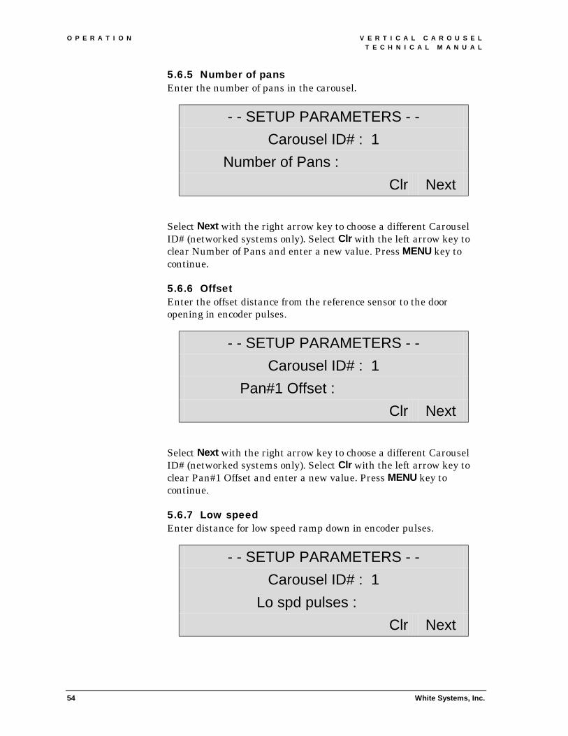
O P E R A T I O N V E R T I C A L C A R O U S E L T E C H N I C A L M A N U A L
54 White Systems, Inc.
5.6.5 Number of pans Enter the number of pans in the carousel.
- - SETUP PARAMETERS - - Carousel ID# : 1
Number of Pans : Clr Next
Select Next with the right arrow key to choose a different Carousel ID# (networked systems only). Select Clr with the left arrow key to clear Number of Pans and enter a new value. Press MENU key to continue.
5.6.6 Offset Enter the offset distance from the reference sensor to the door opening in encoder pulses.
- - SETUP PARAMETERS - - Carousel ID# : 1
Pan#1 Offset : Clr Next
Select Next with the right arrow key to choose a different Carousel ID# (networked systems only). Select Clr with the left arrow key to clear Pan#1 Offset and enter a new value. Press MENU key to continue.
5.6.7 Low speed Enter distance for low speed ramp down in encoder pulses.
- - SETUP PARAMETERS - - Carousel ID# : 1
Lo spd pulses : Clr Next

V E R T I C A L C A R O U S E L O P E R A T I O N T E C H N I C A L M A N U A L
White Systems, Inc. 55
Select Next with the right arrow key to choose a different Carousel ID# (networked systems only). Select Clr with the left arrow key to clear Lo spd pulses and enter a new value. Press MENU key to continue.
5.6.8 Stop window Enter door opening number at Carousel Interface Terminal.
- - SETUP PARAMETERS - - Carousel ID# : 1
Stop window : Clr Next
Select Next with the right arrow key to choose a different Carousel ID# (networked systems only). Select Clr with the left arrow key to clear Stop window and enter a new value. Press MENU key to continue.
5.6.9 Set boards Enter number of door openings.
- - SETUP PARAMETERS - - # of 8Rly/Opto I/O boards :
Change : (+) (-)
Select (+) with the left arrow key to increase number, (-) with the right arrow key to decrease number. Press MENU key to continue.

O P E R A T I O N V E R T I C A L C A R O U S E L T E C H N I C A L M A N U A L
56 White Systems, Inc.
5.6.10 Baud rate Enter baud rate for host communications.
- - SETUP PARAMETERS - - BAUD rate for host communication :
Select : (+) (-)
Select (+) with the left arrow key to increase number, (-) with the right arrow key to decrease number. Press MENU key to continue.
5.6.11 Data bits Enter number of data bits per character for host communications.
- - SETUP PARAMETERS - - # of data bits per
character? Change : (+) (-)
Select (+) with the left arrow key to increase number, (-) with the right arrow key to decrease number. Press MENU key to continue.
5.6.12 Parity Enter parity for host communications.
- - SETUP PARAMETERS - - Parity for host
communication : Select : (+) (-)
Select (+) with the left arrow key to increase number, (-) with the right arrow key to decrease number. Press MENU key to continue.

V E R T I C A L C A R O U S E L O P E R A T I O N T E C H N I C A L M A N U A L
White Systems, Inc. 57
5.6.13 Stop bits Enter stop bits for host communications.
- - SETUP PARAMETERS - - Stop bits for host communication :
Change : (+) (-)
Select (+) with the left arrow key to increase number, (-) with the right arrow key to decrease number. Press MENU key to continue.
5.6.14 Save settings
- - SETUP PARAMETERS - - Save to EEProm
Reboot? No Reboot? Yes No
Select Yes or No with arrow keys. Default selection is No. Press MENU or ENTER key to continue.
M A I N T E N A N C E V E R T I C A L C A R O U S E L T E C H N I C A L M A N U A L
58 White Systems, Inc.
6. MAINTENANCE AND TROUBLESHOOTING 6.1 MAINTENANCE SAFETY
1. Equipment owners should set up a maintenance program to keep the carousel equipment in a safe condition.
2. Only qualified, trained personnel shall perform maintenance on the carousel equipment.
3. Maintenance personnel shall conduct routine inspections, preventive and corrective maintenance, to be sure all safety devices function properly. Maintenance personnel shall keep all warning labels in legible condition.
4. Personnel shall not perform maintenance such as adjustments or lubrication on the carousel equipment when it is in operation.
5. When maintenance personnel stop the carousel equipment for servicing, they must lock out all power to the machine in accordance with the OSHA Lockout/Tagout procedure.
6. Any hazardous conditions discovered during periodic inspections shall be corrected before the carousel equipment is returned to normal operation.
7. Maintenance personnel shall replace and check that all safety devices, access panels, and guards are in working order before starting the equipment for normal operation.

V E R T I C A L C A R O U S E L M A I N T E N A N C E T E C H N I C A L M A N U A L
White Systems, Inc. 59
6.2 MAINTENANCE SCHEDULE MAINTENANCE OPERATION FREQUENCY REF SYSTEM SAFETY Inspect all safety stop devices Every six months or after
performing maintenance -
Check that all warning labels are legible
Every six months -
LUBRICATION Check oil level in gear reducer Before operating for first time 6.4.1 Replace oil in gear reducer One year or 2500 hours of
operation 6.4.2
Roller chain One year 6.4.3 Idler and drive sprocket bearings One year 6.4.4 Stabilizing track One year 6.4.5 Trunnion pivot points One year 6.4.6 INSPECTION Hardware Start up 6.3.1 Drive chain Six months 6.3.2 Drive sprockets Six months 6.3.3 Load chain Six months 6.3.4 Load chain wheels Six months 6.3.5 Stabilizing arm wheels Six months 6.3.6 Scissor arms Six months 6.3.7 Pans Six months 6.3.8 Curve tracks Six months 6.3.9 Photo eyes Six months 6.3.10
POSSIBLE UNEXPECTED MACHINE OPERATION. BEFORE ATTEMPTING TO SERVICE OR ADJUST THE CAROUSEL MECHANISM, REMOVE ALL POWER TO THE CONTROL ENCLOSURE. INSTALL SAFETY LOCKOUT DEVICES TO ENSURE MECHANISM DOES NOT START UNEXPECTEDLY.
6.3 CAROUSEL INSPECTION 6.3.1 Hardware Before putting a carousel into service for the first time, or after overhauling, check the pan mounting hardware, load chain take-up assemblies and drive chain take-up assembly for loose bolts and missing hardware.
6.3.2 Checking drive chain The roller chain connecting the speed reducer sprocket to the drive sprocket is tensioned during installation. As the chain wears, excessive chain stretch will cause errors in carousel pan positioning. When the drive chain deflects more than one inch, chain tension must be readjusted (see Section 4.1.2).

M A I N T E N A N C E V E R T I C A L C A R O U S E L T E C H N I C A L M A N U A L
60 White Systems, Inc.
6.3.3 Checking drive sprockets Examine the drive sprocket teeth for wear. Check for broken, worn, or chipped teeth that indicate a misalignment or problem with the load chain.
6.3.4 Checking load chain Examine the load chain for correct tension. If slack is seen at the drive sprockets, readjust preload (see Section 4.1.1). The chain should appear slightly wet with lubricant. A reddish-brown color on the chain surfaces indicates that the chain was not adequately lubricated.
6.3.5 Checking load chain wheels Examine the nylon wheels for flat spots or unusual wear. Cracked or broken wheels will seize without affecting the overall motion of the carousel. Loose load chains or overloaded pans can damage the wheels.
6.3.6 Checking stabilizing arm wheels Examine the nylon wheels for cracks or flat spots. Misaligned stabilizer tracks or loose load chains can damage the wheels.
6.3.7 Checking scissors arms Examine the trunnion assemblies for bent scissor arms, indicating a jam or other mechanical problem. Check the pivot bushings and chain pins for excessive wear, indicating overloaded pans.
6.3.8 Checking pans and shelves Examine the pan dividers and shelves for loose hardware. Check for bent shelves or pans that are not level.
6.3.9 Checking the stabilizing track Examine the stabilizing tracks for cracked or bent rails, especially at the end sections. Incorrectly tensioned load chains or incorrectly adjusted curved tracks can damage the inside and outside rails.
6.3.10 Checking photo eyes Check the LED on each photo eye (hold a reflector in front of the reference sensor). If a LED is not lit, examine the lens for excessive dust buildup. Wipe lens and reflector with a clean soft cloth and a mild detergent solution. Do not use solvents. If the LED does not light after cleaning, adjust alignment and sensitivity setting. If the sensor continues to malfunction, see Section 6.4.7.

V E R T I C A L C A R O U S E L M A I N T E N A N C E T E C H N I C A L M A N U A L
White Systems, Inc. 61
6.4 CAROUSEL MAINTENANCE 6.4.1 Checking reducer oil level The carousel drive reducer is filled with oil prior to shipment. Check the oil level prior to putting the unit into operation (see Section 4.1.2).
6.4.2 Replacing oil in reducer Replace the oil every twelve months or 2500 operating hours. Refill with Sitter Oil Co. Valvata J460 or equivalent.
6.4.3 Lubricating roller chain Use a lithium EP-2 grease or equivalent.
6.4.4 Lubricating idler and drive sprocket bearings All bearings are prelubricated with a No. 2 consistency lithium base grease. When relubricating, use a lithium EP-2 grease or equivalent.
6.4.5 Lubricating stabilizing track Use a lithium EP-2 grease or equivalent.
6.4.6 Lubricating trunnion pivot points Use a lithium EP-2 grease or equivalent.
6.4.7 Replacing sensors and cables Each sensor has a twist-lock connector. Unplug the connector to replace a sensor without disturbing the cable. If a cable requires replacement, route the new cable exactly as the old one, replacing all cable ties. Check the new cable for clearance with surrounding components.
HAZARD OF ELECTRICAL SHOCK OR BURN. FAILURE TO FOLLOW SAFE ELECTRICAL PRACTICES CAN RESULT IN SERIOUS INJURY OR DEATH. BEFORE OPENING PANEL INSURE THAT ALL SOURCES OF POWER ARE TURNED OFF AND LOCKED OUT.
HAZARD OF ELECTRICAL SHOCK OR BURN. POTENTIALLY LETHAL VOLTAGES EXIST IN AC DRIVES FOR SEVERAL MINUTES AFTER POWER IS REMOVED. BEFORE SERVICING AN AC DRIVE, IN THE CONTROL ENCLOSURE, WAIT UNTIL THE DC BUS IS DISCHARGED AND THE BUS CHARGED LIGHT IS OUT.

M A I N T E N A N C E V E R T I C A L C A R O U S E L T E C H N I C A L M A N U A L
62 White Systems, Inc.
6.5 TROUBLESHOOTING GUIDE PROBLEM POSSIBLE CAUSE CORRECTIVE ACTION Disconnect switch ON, no Carousel Interface Terminal light
No power to panel Check input power
Line fuses open Check fuses, find fault, replace fuses Power supply fuses open Check fuses, find fault, replace fuses Terminal cable connector
loose Check connector at terminal block behind idle panel
Cannot enable carousel for operation
EMERGENCY STOP button pressed
Reset EMERGENCY STOP button, press Clear arrow key
Door opening photo eye blocked
Clear sensor, press Clear arrow key
Touch bar activated Clear door opening, press Clear arrow key
Access panel open Close panel, press Clear arrow key Light curtain blocked
(optional) Clear door opening, press Clear arrow key
Pans will not move Control fault Clear fault, press Clear arrow key Drive fuses open Check fuses, find fault, replace fuses Drive malfunction Replace drive Brake shaft key sheared Replace key Brake failure Adjust or replace brake Drive chain failure Replace chain, see Section 4.1.2 Speed reducer failure Replace reducer Carousel will not home
Reference photo eye malfunction
Check photo eye, adjust or replace, see Section 6.3.10
Drive malfunction Replace drive Encoder malfunction Check and replace encoder Pan position error Pan# 1 offset set incorrectly Change offset, see Section 5.6.6 Chain stretch Adjust load chain preload, see
Section 4.1.1 Encoder malfunction Check and replace encoder Pan not level Level pan, see Section 4.3.5 Brake failure Adjust or replace brake Brake chatters, smells burnt
Insufficient voltage Check input power
Pressure plate not releasing Adjust or replace brake Control relay failure Replace CR1 relay Broken nylon wheel Excessive load in pan Reduce load Pan binding in transition Adjust load chain preload, see
Section 4.1.1 Bent scissor arm Interference between pans Clear interference, replace arm Obstruction between arm and
track Clear obstruction, replace arm
Door lock inoperable Binding lock rod Open-up socket hole in tracks Loose set screw in handle Apply Loctite, tighten setscrew Doors open unevenly Broken cable Remove door, replace cable

V E R T I C A L C A R O U S E L D E S I G N D A T A T E C H N I C A L M A N U A L
White Systems, Inc. 63
7. DESIGN DATA 7.1 SPECIFICATIONS
7.1.1 Performance
Vertical Carousel Performance Characteristics Maximum pan speed 40 feet/minute Horsepower 3 and 5 Maximum imbalance 1,800 pounds @ 3HP and 3,000 pounds @ 5HP Maximum pan capacity 600 and 800 pounds Pan depth (inches) 24.5, 18.5, 16.5, 15.5 Pan width (inches) 130, 112, 106, 100, 95, 72, 60 Pan pitch (inches) 22.5, 21.0, 19.5, 18.0, 16.5, 15.0, 13.5, 12.0, 10.5
7.1.2 Load chain safety factor Two #120 chains support the pans. They have a static safety factor of 6:1.
7.1.3 Bearings All ball bearings have a B1O life of 25,000 hours, and are a sealed, heavy-duty design.
7.1.4 Footprint !" The depth of model 2400 is 67.75 inches. !" The depth of models 1800, 1600, and 1500 is 56.25 inches. !" Carousel width is equal to the pan width + 24.5 inches.
7.1.5 Height The overall height of the carousel ranges from 8 feet to 36 feet.
7.1.6 Power requirements Standard power requirements are 200V to 230V AC, 60Hz, three-phase, 30A. As an option, the carousel can use 400V to 460V AC, 60Hz, three-phase, 15A.
7.1.7 Environmental considerations The I/E is capable of operating in a temperature range of 33°F to 104°F with a relative humidity of 5-95% (without condensation).
7.1.8 Sound level The I/E sound levels are less than 80db (A scale, slow response) at a distance of 5 feet.
7.1.9 Service life The I/E is designed with the appropriate safety factors to ensure the unit is capable of functioning in a 7-24-365 environment.

D E S I G N D A T A V E R T I C A L C A R O U S E L T E C H N I C A L M A N U A L
64 White Systems, Inc.
7.2 OPTIONAL EQUIPMENT 7.2.1 Dust cover The dust cover consists of three identical sheet metal panels that enclose the top of the carousel.
7 . 2 . 1 . 1 I N S T A L L A T I O N
1. Orient the panels with reinforcing flanges down (see Figure 33).
2. Place the two end panels.
3. Place the center panel so that it overlaps the side panels.
4. Secure with #10 x 3/4 self-drilling screws.
Figure 33. DUST COVER INSTALLATION
HOLES DRILLED AT ASSEMBLY
TOP OF CAROUSEL
SELF-DRILLING SCREWS

V E R T I C A L C A R O U S E L D E S I G N D A T A T E C H N I C A L M A N U A L
White Systems, Inc. 65
7.2.2 Hand crank 7 . 2 . 2 . 1 I N S T A L L A T I O N
1. Depress the EMERGENCY STOP push button on the supervisor's panel.
2. Remove the lower access door to provide access to the brake lever.
3. Remove the 1-inch channel from the crank mounting bracket.
4. Place the crank bracket on the corner of the counter (see Figure 34).
5. Insert the 1-inch channel between the counter flange and thumbscrews.
6. Tighten thumbscrews to clamp to counter flange.
7. Install brake release rod by inserting it through the hole in the clip on the mounting bracket and through the hole on the brake lever.
8. Install hairpin clip to end of release rod.
9. Test the pan load distribution by pulling the brake release rod to the brake OFF position. If the pans start to rotate, immediately engage the brake by pushing the rod to the brake ON position. Do not use the hand crank. Remove the crank mounting hardware.
PAN ROTATION INDICATES THAT THE FRONT TO BACK LOAD DISTRIBUTION EXCEEDS RECOMMENDED LIMITS AND IT IS NOT SAFE TO USE THE HAND CRANK.
If no pan movement is observed, continue to step 10.
10. Open the supervisor's panel by turning the latch release with a hex key. The latch release is located in the left door channel.
11. Place the end of the right angle gear drive on the squared end of the motor shaft.
12. Place the hand crank tube through the socket on the mounting bracket. Align the top of the crank assembly with the top of the right angle drive. Tighten thumbscrews to secure.

D E S I G N D A T A V E R T I C A L C A R O U S E L T E C H N I C A L M A N U A L
66 White Systems, Inc.
13. Loosen the front collar of the right angle drive and insert the crank shaft. Slide the collar back to the face of the right angle drive and lock in place.
7 . 2 . 2 . 2 O P E R A T I O N
1. Pull the brake release rod.
2. Turn crank handle. Ten rotations will provide approximately 2 1/2 inches of pan travel.
3. Engage brake after turning crank.
4. Remove hand crank and close access panels before resuming normal carousel operation.
Figure 34. HAND CRANK INSTALLATION
BRAKE RELEASE ROD
BRAKE
RIGHT ANGLE DRIVE
COUNTER MOTOR
CRANK HANDLE

V E R T I C A L C A R O U S E L D E S I G N D A T A T E C H N I C A L M A N U A L
White Systems, Inc.
7.2.3 Clean room options 7 . 2 . 3 . 1 A U T O M A T I C A C C E S S D O O R S
Automatic doors maintain clean room integrity when used on carousels with multiple openings. A computer control allows only one open door during a transaction. When the transaction is complete and personnel are clear, the door closes automatically.
Figure 35. PNEUMATIC DOOR ASSEMBLY
67
The doors are actuated by a pneumatic cylinder attached to the upper door (see Figure 35). A double-acting pneumatic valve, connected to the carousel controller, directs air to the cylinder. A reed switch mounted on the cylinder signals the controller when the doors are closed.
Carousels equipped with automatic doors use a light curtain to protect personnel from potential pinch points (see Figure 36). The light curtain system scans the door opening with infrared light beams. When a beam is interrupted, the system prevents door closure and pan rotation.

D E S I G N D A T A V E R T I C A L C A R O U S E L T E C H N I C A L M A N U A L
68 White Systems, Inc.
7 . 2 . 3 . 2 I N T E R N A L S I D E E N C L O S U R E
To isolate areas where particulate is generated, both drive and idler sides of the carousel have internal baffle plates (see Figure 37). The baffles cover all but a 2-inch slot for trunnion stud movement. When the inside of the machine is pressurized, any particulate generated behind the baffles becomes trapped in the filtration system at the bottom of the unit. Clean air exhausts from the machine through ports located at the sides of the carousel.
Figure 36. LIGHT CURTAIN INSTALLATION
FRONT SIDE
Light Curtain
Control Enclosure
Light Curtain Assy

V E R T I C A L C A R O U S E L D E S I G N D A T A T E C H N I C A L M A N U A L
White Systems, Inc. 69
Figure 37. CLEAN ROOM AIR BAFFLE SYSTEM
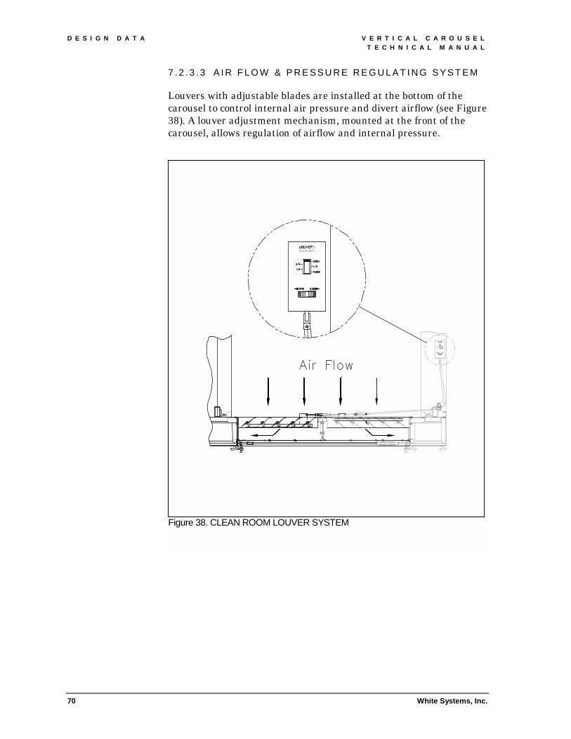
D E S I G N D A T A V E R T I C A L C A R O U S E L T E C H N I C A L M A N U A L
70 White Systems, Inc.
7 . 2 . 3 . 3 A I R F L O W & P R E S S U R E R E G U L A T I N G S Y S T E M
Louvers with adjustable blades are installed at the bottom of the carousel to control internal air pressure and divert airflow (see Figure 38). A louver adjustment mechanism, mounted at the front of the carousel, allows regulation of airflow and internal pressure.
Figure 38. CLEAN ROOM LOUVER SYSTEM

V E R T I C A L C A R O U S E L D E S I G N D A T A T E C H N I C A L M A N U A L
White Systems, Inc. 71
7.2.4 RS-232 interface port operation and message format
7 . 2 . 4 . 1 O P E R A T I O N
The carousel must be in Host Computer Mode to respond to transmissions from the RS-232 port. If the carousel control is in Local Control Mode, it can receive information, but cannot rotate the pans.
There are two modes of operation: host-directed picks and message database picks. Host-directed picks are "real time" transactions directed by the host computer. Message database picks are directed to any door opening on the carousel and stored in the message database.
On carousels with multiple door openings, the operator must check the pan number to see if a pan has stopped for his/her pick. To eliminate operator confusion, White recommends the use of light bars on multiple opening carousels. Light bars automatically indicate the active opening and correct pick location.
7 . 2 . 4 . 2 M E S S A G E F O R M A T
The Series 2400 carousel control equipped with an RS-232 interface port will accept synchronous point-to-point communications (up to 9600 baud) from a host computer. The transmission must be half duplex, ASCII. The carousel control ignores "line feeds" and "nulls" in order to be compatible with most half duplex protocols. The number of data bits per character, stop bits, parity, and baud rate is configurable at the carousel control.
Communications are originated by the host. The carousel control will echo each character back to the host, followed by a carriage return. If the carousel control receives a character out of context or an invalid command, it will send back an ASCII question mark ('?) followed by a carriage return. The host must handle lowercase alpha characters and strings in order to “interpret” data from the carousel control.
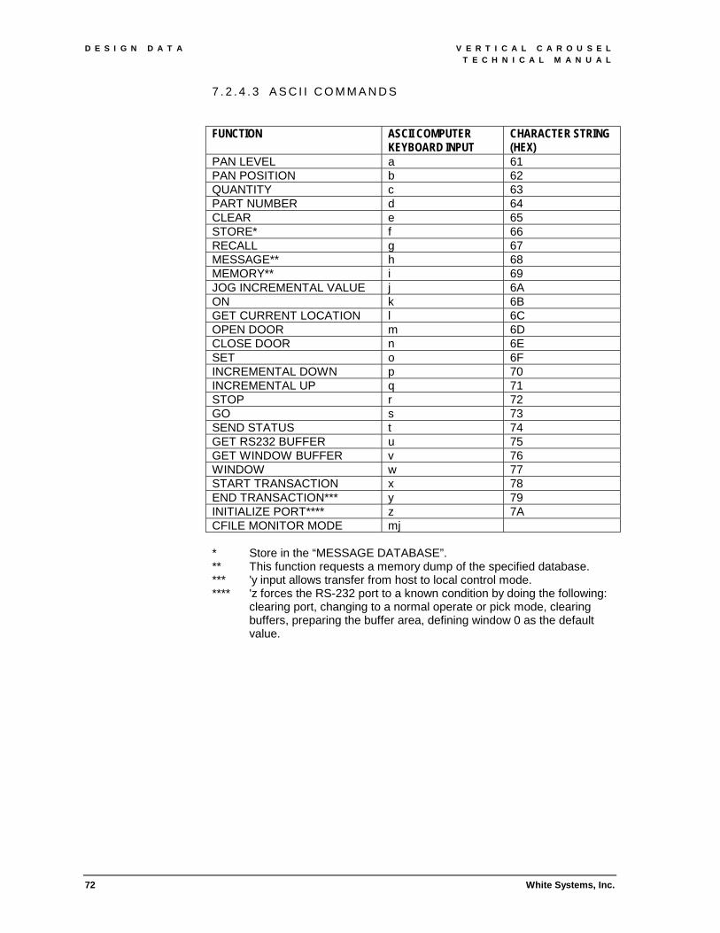
D E S I G N D A T A V E R T I C A L C A R O U S E L T E C H N I C A L M A N U A L
72 White Systems, Inc.
7 . 2 . 4 . 3 A S C I I C O M M A N D S
FUNCTION ASCII COMPUTER
KEYBOARD INPUT CHARACTER STRING (HEX)
PAN LEVEL a 61 PAN POSITION b 62 QUANTITY c 63 PART NUMBER d 64 CLEAR e 65 STORE* f 66 RECALL g 67 MESSAGE** h 68 MEMORY** i 69 JOG INCREMENTAL VALUE j 6A ON k 6B GET CURRENT LOCATION l 6C OPEN DOOR m 6D CLOSE DOOR n 6E SET o 6F INCREMENTAL DOWN p 70 INCREMENTAL UP q 71 STOP r 72 GO s 73 SEND STATUS t 74 GET RS232 BUFFER u 75 GET WINDOW BUFFER v 76 WINDOW w 77 START TRANSACTION x 78 END TRANSACTION*** y 79 INITIALIZE PORT**** z 7A CFILE MONITOR MODE mj
* Store in the “MESSAGE DATABASE”. ** This function requests a memory dump of the specified database. *** 'y input allows transfer from host to local control mode. **** 'z forces the RS-232 port to a known condition by doing the following:
clearing port, changing to a normal operate or pick mode, clearing buffers, preparing the buffer area, defining window 0 as the default value.
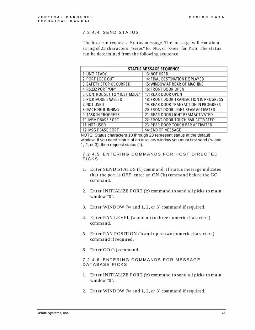
V E R T I C A L C A R O U S E L D E S I G N D A T A T E C H N I C A L M A N U A L
White Systems, Inc. 73
7 . 2 . 4 . 4 S E N D S T A T U S
The host can request a Status message. The message will contain a string of 23 characters: "zeros" for NO, or "ones" for YES. The status can be determined from the following sequence.
STATUS MESSAGE SEQUENCE
1: UNIT READY 13: NOT USED 2: PORT LOCK OUT 14: FINAL DESTINATION DISPLAYED 3: SAFETY STOP OCCURRED 15: WINDOW AT REAR OF MACHINE 4: RS232 PORT “ON” 16: FRONT DOOR OPEN 5: CONTROL SET TO “HOST MODE” 17: REAR DOOR OPEN 6: PICK MODE ENABLED 18: FRONT DOOR TRANSACTION IN PROGRESS 7: NOT USED 19: REAR DOOR TRANSACTION IN PROGRESS 8: MACHINE RUNNING 20: FRONT DOOR LIGHT BEAM ACTIVATED 9: TASK IN PROGRESS 21: REAR DOOR LIGHT BEAM ACTIVATED 10: MEM DBASE SORT 22: FRONT DOOR TOUCH BAR ACTIVATED 11: NOT USED 23: REAR DOOR TOUCH BAR ACTIVATED 12: MSG DBASE SORT $4: END OF MESSAGE
NOTE: Status characters 10 through 23 represent status at the default window. If you need status of an auxiliary window you must first send ('w and 1, 2, or 3), then request status ('t). 7 . 2 . 4 . 5 E N T E R I N G C O M M A N D S F O R H O S T D I R E C T E D P I C K S
1. Enter SEND STATUS ('t) command. If status message indicates that the port is OFF, enter an ON ('k) command before the GO command.
2. Enter INITIALIZE PORT ('z) command to send all picks to main window "0".
3. Enter WINDOW ('w and 1, 2, or 3) command if required.
4. Enter PAN LEVEL ('a and up to three numeric characters) command.
5. Enter PAN POSITION ('b and up to two numeric characters) command if required.
6. Enter GO ('s) command.
7 . 2 . 4 . 6 E N T E R I N G C O M M A N D S F O R M E S S A G E D A T A B A S E P I C K S
1. Enter INITIALIZE PORT ('z) command to send all picks to main window "0".
2. Enter WINDOW ('w and 1, 2, or 3) command if required.

D E S I G N D A T A V E R T I C A L C A R O U S E L T E C H N I C A L M A N U A L
74 White Systems, Inc.
3. Enter PAN LEVEL ('a and up to three numeric characters) command.
4. Enter PAN POSITION ('b and up to two numeric characters) command if required.
5. Enter STORE ('f) command.
7 . 2 . 4 . 7 E N T E R I N G J O G C O M M A N D S
The host can jog the machine an incremental amount by sending a ('p) for jog down and a ('q) for jog up. The machine will move the distance defined in the jog incremental buffer. The quantity in the jog incremental buffer can be changed using the following procedure:
Enter QUANTITY ('c and up to four numeric characters) command.
Enter JOG INCREMENTAL VALUE ('j) to store input in the jog incremental buffer
7 . 2 . 4 . 8 R E T R I E V I N G I N F O R M A T I O N
The MEMORY ('i) command requests the information in the message database. The control responds as follows:
An ‘A followed by a carriage return, is transmitted to the host. This indicates that the database for the window is an AMK type.
Then the requested database is transmitted to the host. A seven-character field, followed by carriage return, is transmitted for each item in the database. The first three characters are the pan level, the fourth character is a space, the fifth and sixth characters are the pan position, and the last character is a space.
The transmission is then terminated with a character $4 (EOT) followed by a carriage return.
The GET RS232 BUFFER ('u) command and the GET WINDOW BUFFER ('v) commands request the information in the RS232 buffer and the window buffer respectively. The control responds with a 24-character field followed by a carriage return. Then the transmission is terminated with a character$4 (EOT) followed by a carriage return. The first three characters are the pan level, the fourth character is a space, the fifth and sixth characters are the pan position, the seventh character is a space, and the last twelve characters are the part numbers.

V E R T I C A L C A R O U S E L T E C H N I C A L M A N U A L
White Systems, Inc. 75
8. APPENDIX 8.1 MODEL NUMBER
T A 2 2 6 0
Series Number Location of Controls: T = 2400 0 = Above opening E = 1800 1 = In counter S = 1600 2 = Manual F = 1500 3 = Remote Pan Capacity: 6 = 600 Lbs. 8 = 800 Lbs. Pan Pitch: A = 10.5 inches B = 12.0 inches C = 13.5 inches Number of Pans D = 15.0 inches E = 16.5 inches F = 18.0 inches G = 19.5 inches H = 21.0 inches I = 22.5 inches M = Mixed

V E R T I C A L C A R O U S E L T E C H N I C A L M A N U A L
76 White Systems, Inc.
8.2 WARRANTY
White Systems warrants that the system and equipment manufactured by White, when used for ordinary purposes for which such equipment is designed, shall be free of defects in workmanship and material for a period of one (1) year from the date of shipment, based on a one shift per day operation. During the warranty period and upon proof of claim by Customer, White will replace F.O.B. White factory, or repair, excluding installation, any part proving defective in material or workmanship, subject to the following conditions: (a) Customer shall return defective equipment and components to White upon request. (b) This warranty applies only to system equipment properly used and maintained and does not apply to any equipment which has been subjected to misuse, neglect or accident, or which has been installed, operated, repaired, altered or modified other than in accordance with instructions or written authorization by White. (c) This warranty does not apply to any equipment, control components or software not manufactured by White, and Customer’s sole warranty with respect to such items shall be that of the manufacturer, if any. Customer’s remedies and White’s obligations in connection with any claim made under this warranty shall be limited to repair or, at White’s option, replacement of the equipment or part thereof which is found to be defective. Labor performed at the worksite with regard to such claims is not included in this warranty. Customer shall be responsible for the normal maintenance and repair of the Equipment and shall perform the same in accordance with generally accepted maintenance procedures or such other procedures as are set forth in maintenance and repair manuals provided by White to Customer. White shall not be responsible for and shall not be obligated to pay or to reimburse Customer for (a) any materials furnished by third parties for use in connection with the Equipment if the same was undertaken or furnished without mutual prior written consent or (c) any loss of damage arising from improper operation or maintenance of the equipment of from ordinary wear and tear. White Systems, Inc. 30 Boright Avenue Kenilworth, New Jersey 07033

V E R T I C A L C A R O U S E L T E C H N I C A L M A N U A L
White Systems, Inc. 77
8.3 RETURNED GOODS White Systems Inc. policy requires a Return Authorization Number or "RAN" for all goods returned. This Return Authorization Number MUST be prominently displayed on the outside of ALL packages returned, on all related paperwork, and referenced in any telephone conversations with WHITE personnel. Packages which do not display the Return Authorization Number will be refused by WHITE and returned to sender. TO OBTAIN A RETURN AUTHORIZATION NUMBER: WHITE Customer One Protection personnel will assign the Return Authorization Number during the normal work week, Monday through Friday, between the hours of 8:30 a.m. and 5:00 p.m. (Eastern Standard Time) at : 800-571-8822. THE FOLLOWING INFORMATION MUST BE PROVIDED TO OBTAIN THE RETURN AUTHORIZATION NUMBER:
#" Name of caller and contact telephone number #" Ship to and Bill to information - contact person #" Customer Purchase Order number #" Part description of malfunction #" Complete description of malfunction #" Detailed return reason #" Part application, i.e., required for carousel #" Serial number of system and individual components
COMPONENTS COVERED UNDER A MAINTENANCE AGREEMENT: White Systems, Inc. will ship a replacement for any defective component covered under warranty or Maintenance Agreement. The caller, after providing the above listed information, will be instructed to return the defective component(s) to WHITE. Upon receipt of the component, a full credit will be issued subject to the note below. The customer Purchase Order is issued to cover replacement cost only in the event the defective component is not returned.
NOTE: All repairs necessary to restore the component to its original appearance, i.e., remove paint, decals, repair scratches or dents, customer alterations, including but not limited to replacement of components are not covered under warranty. Customer will be billed for such restorative repairs at the prevailing rates.1
COMPONENTS UNDER WARRANTY: White Systems, Inc. will repair or replace, if necessary, and ship within ten (10) working days of receipt of defective goods. WHITE will repair the component(s) to a functional state. No aesthetic repairs will take place unless specified by the customer. WHITE will absorb surface shipping charges on warranty replacement and repaired parts shipped by WHITE. The customer is responsible for any expedited shipping charges, as well as the freight on the return of the defective component.
1 Irreparable components will not be replaced without prior customer approval.
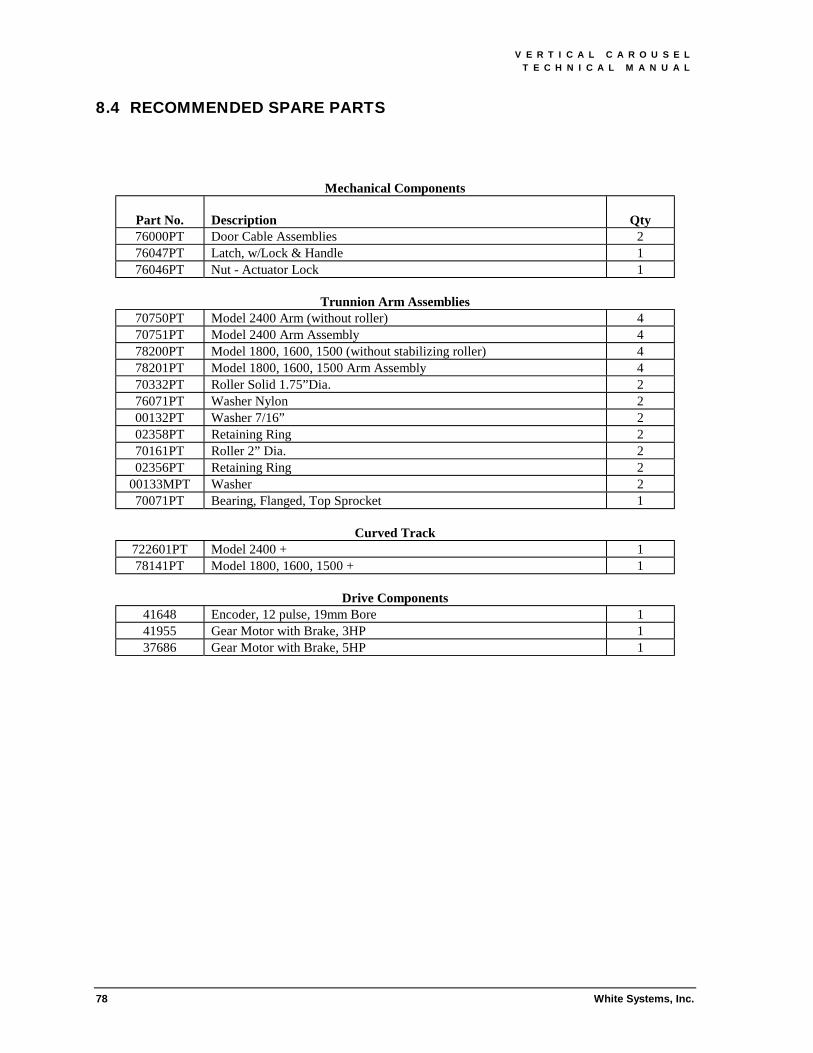
V E R T I C A L C A R O U S E L T E C H N I C A L M A N U A L
78 White Systems, Inc.
8.4 RECOMMENDED SPARE PARTS
Mechanical Components Part No.
Description
Qty
76000PT Door Cable Assemblies 2 76047PT Latch, w/Lock & Handle 1 76046PT Nut - Actuator Lock 1
Trunnion Arm Assemblies
70750PT Model 2400 Arm (without roller) 4 70751PT Model 2400 Arm Assembly 4 78200PT Model 1800, 1600, 1500 (without stabilizing roller) 4 78201PT Model 1800, 1600, 1500 Arm Assembly 4 70332PT Roller Solid 1.75”Dia. 2 76071PT Washer Nylon 2 00132PT Washer 7/16” 2 02358PT Retaining Ring 2 70161PT Roller 2” Dia. 2 02356PT Retaining Ring 2
00133MPT Washer 2 70071PT Bearing, Flanged, Top Sprocket 1
Curved Track
722601PT Model 2400 + 1 78141PT Model 1800, 1600, 1500 + 1
Drive Components
41648 Encoder, 12 pulse, 19mm Bore 1 41955 Gear Motor with Brake, 3HP 1 37686 Gear Motor with Brake, 5HP 1

V E R T I C A L C A R O U S E L T E C H N I C A L M A N U A L
White Systems, Inc. 79
Control System
Part No.
Description
Qty
38488 Photo Eye Receiver 52266 (Banner) 2 38489 Photo Eye Receiver 52267 (Banner) 2 7870 Reference Sensor (A-B) 1
38490 Photo Eye Emitter 37989 (Banner) 2
40960 Cable Assembly J-Block 50 ft 1 40960 Multiport Hirschmann Block (Hirschmann) 1 40807 Overlay with Membrane Keypad 1 40808 Display, LCD 4x20 1 38920 Cable Assy, 18" 1 41644 Piezo Panel, Tone Alarm 1 39637 Peripheral, Bus 4 Serial 1 20394 Relay, 4PDT, 12VDC 1 30527 Fuse, Buss LP-CC-30, 30A, 600V 5 54253 Fuse, Time Delay, 10A, FNQ-10 5 38258 Board Computer, 4K, E2P, 256K RAM 1 38259 Opto Isolated, 8 Input, 8 Relay 1 39322 Board, Encoder, Interface, A2B2 1 40695 Power Supply, +5V, +12V, 60 Watt 1 40806 Carousel Interface Assembly 1 40894 Cable, Encoder to SBC-332 1 40918 Cable, SBC-332 to DC Power Supply 1 40919 Cable, Ref Sensor to SBC-332 1 40965 Cable Assembly, 50 ft (Hirschmann) 1 54257 Fuse, Time Delay, 20A, FNQ-20 5 40692 Disconnect Switch, 32A, 3 Pole 1 41317 Contactor, 12V, 100-C30ZQ10 (A-B) 1 40694 Drive, 3HP, 230V AC, Semipower 1 41460 Drive, 5HP, 230V AC, Semipower 1 42406 Light Curtain Emitter 1 42407 Light Curtain Receiver 1 42408 Light Curtain Control Box 1