247 belfast 11apr13
TRANSCRIPT

1
Introduction to EC7 Part 1: Design and verification procedures Parameter characterisation
Brian Simpson Arup Geotechnics
BP188.1
Northern Ireland Geotechnical Group Seminar on EC7 11 April 2013

2
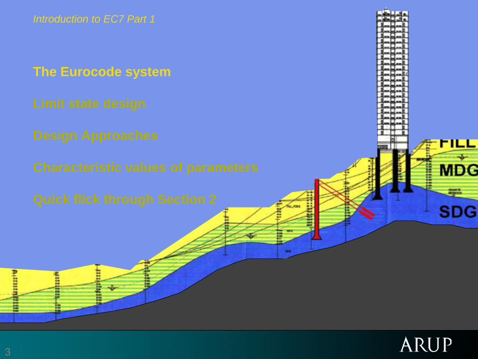
Introduction to EC7 Part 1 The Eurocode system Limit state design Design Approaches Characteristic values of parameters Quick flick through Section 2
3
Introduction to EC7 Part 1 The Eurocode system Limit state design Design Approaches Characteristic values of parameters Quick flick through Section 2

4
Eurocode 7 - Geotechnical design
• 1957: European Economic Community – Treaty of Rome
• 1975: Commission of the European Community - Eurocodes • 1981: European national geotechnical societies • 1987: First draft EC7
• 1989: Comité Européen de Normalisation (CEN/TC250/SC7) • 1994/5: ENV1997 (European Vornorm) + NAD’s • 2004: EN1997-1 + UK National Annex (2007?)
• 2007: EN1997-2 + UK National Annex (2008??) • 2009: EN1997-1 corrigendum
Main discipline? Ever used Eurocodes? Ever used EC7?

5 ©
The Eurocode system BP72.9 BP106.3 BP111.4 BP112.4 BP124-T1.9
24. 3
The Eurocode system (CEN-TC250)
EN 1990 Eurocode 0 Basis of design EN 1991 Eurocode 1 Actions on structures EN 1992 Eurocode 2 Design of concrete structures EN 1993 Eurocode 3 Design of steel structures EN 1994 Eurocode 4 Design of composite steel and concrete structures EN 1995 Eurocode 5 Design of timber structures EN 1996 Eurocode 6 Design of masonry structures EN 1997 Eurocode 7 Geotechnical design EN 1998 Eurocode 8 Design of structures for earthquake resistance. EN 1999 Eurocode 9 Design of aluminium alloy structures
Other related documents: CEN, commentaries, websites

6
The whole range of documents
Design: BSEN1997-1 BSEN1997-2
Ground properties
CEN/TC341 Standards
ISO/CEN Standards
Other Structural Eurocodes
e.g. EC3 Part 5
Execution Standards
CEN/TC288
Geotechnical
Projects
NCCI eg PD6694-1

7
This picture shows an
Execution BP190a.13
BP195a.115
In Eurocodes, you execute the design … … not the designer! BP124-T1.35
8
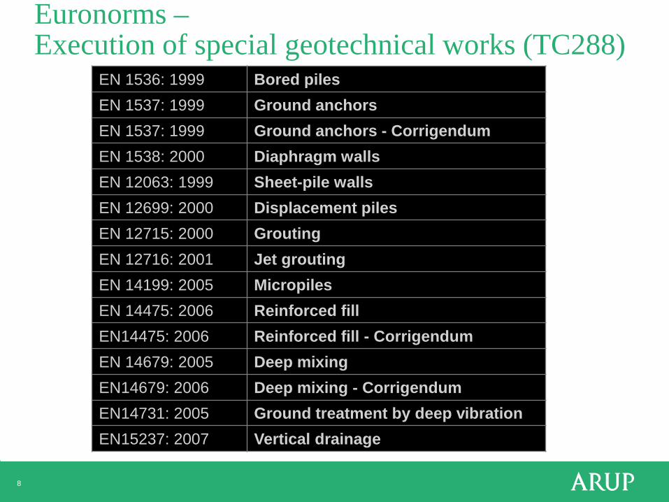
Euronorms – Execution of special geotechnical works (TC288)
EN 1536: 1999 Bored piles EN 1537: 1999 Ground anchors EN 1537: 1999 Ground anchors - Corrigendum EN 1538: 2000 Diaphragm walls EN 12063: 1999 Sheet-pile walls EN 12699: 2000 Displacement piles EN 12715: 2000 Grouting EN 12716: 2001 Jet grouting EN 14199: 2005 Micropiles EN 14475: 2006 Reinforced fill EN14475: 2006 Reinforced fill - Corrigendum EN 14679: 2005 Deep mixing EN14679: 2006 Deep mixing - Corrigendum EN14731: 2005 Ground treatment by deep vibration EN15237: 2007 Vertical drainage

9
The whole range of documents
Design: BSEN1997-1 BSEN1997-2
Ground properties
CEN/TC341 Standards
ISO/CEN Standards
Other Structural Eurocodes
e.g. EC3 Part 5
Execution Standards
CEN/TC288
Geotechnical
Projects
NCCI eg PD6694-1

10
The whole range of documents
Design: BSEN1997-1 BSEN1997-2
Ground properties
CEN/TC341 Standards
ISO/CEN Standards
Other Structural Eurocodes
e.g. EC3 Part 5
Execution Standards
CEN/TC288
Geotechnical
Projects
NCCI eg PD6694-1

11
NCCI, PDs, Residual Documents and BSs (NCCI = Non-Conflicting Complementary Information)
• CEN required that conflicting national standards were withdrawn by 2010.
• “Published Documents” – BSI documents which do not have the status of a BS but provide NCCI.
• PD 6694-1, Recommendations for the design of structures subject to traffic loading to BS EN 1997-1 - Advises a slightly higher FOS for non-embedded highway walls
• Where does this leave other BS’s?
- BS8002 – Earth retaining structures –withdrawn 31 March 2010. CIRIA C580 to be revised? - BS8004 – Foundations –withdrawn 31 March 2010. - BS8006 – Strengthened/reinforced soils and other fills – revised - BS8081 – Ground anchorages – unchanged for the time being - BS6031 – Earthworks –revised – possible EN to be drafted. - BS1377 – Soil testing – being revised - BS5930 – Site investigation –revised consistent with EC7

12
Introduction to EC7 Part 1 The Eurocode system Limit state design Design Approaches Characteristic values of parameters Quick flick through Section 2

13
Limit state design
• “states beyond which the structure no longer satisfies the relevant design criteria”
• partial factor design ?
• probabilistic design ?
• concentration on what might go wrong

14
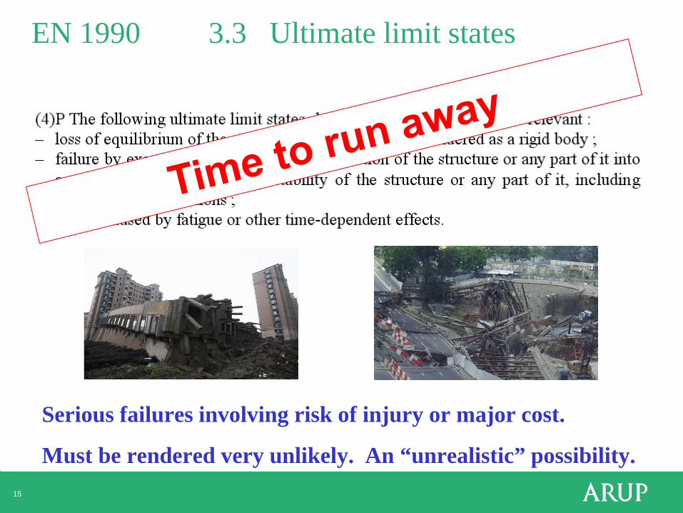
EN 1990 3.3 Ultimate limit states
Serious failures involving risk of injury or major cost.
Must be rendered very unlikely. An “unrealistic” possibility.
15
EN 1990 3.3 Ultimate limit states
Serious failures involving risk of injury or major cost.
Must be rendered very unlikely. An “unrealistic” possibility.

16
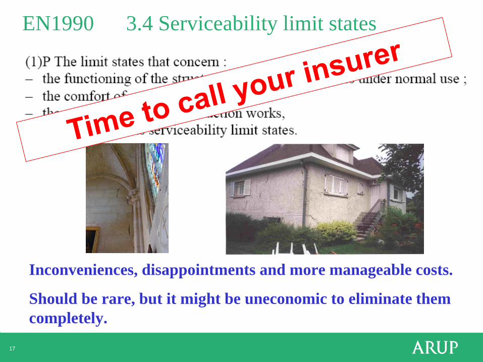
EN1990 3.4 Serviceability limit states
Inconveniences, disappointments and more manageable costs.
Should be rare, but it might be uneconomic to eliminate them completely.
17
EN1990 3.4 Serviceability limit states
Inconveniences, disappointments and more manageable costs.
Should be rare, but it might be uneconomic to eliminate them completely.

18
Limit state design
• An understanding of limit state design can be obtained by contrasting it with “working state design”.
• Working state design: Analyse the expected, working state, then apply margins of safety.
• Limit state design: Analyse the unexpected states at which the structure has reached an unacceptable limit.
• Make sure the limit states are unrealistic (or at least unlikely).
19
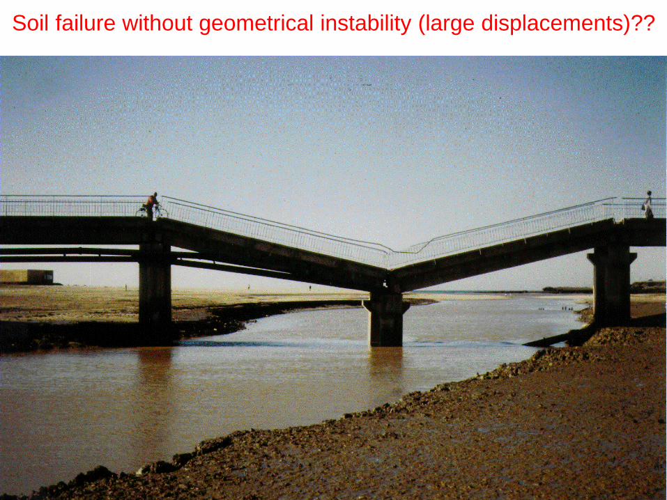
Soil failure without geometrical instability (large displacements)??
BP190a.28

20
Grand Egyptian Museum
•Governed by SLS

21 Coventry University Engineering and Computing Building

22
Coventry University Engineering and Computing Building
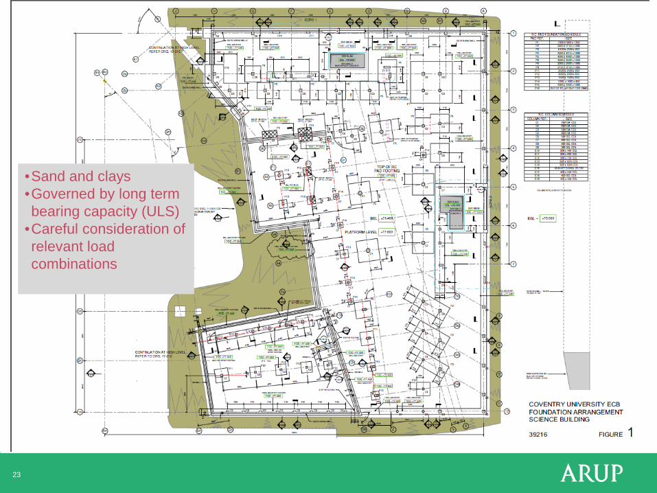
23
•Sand and clays •Governed by long term bearing capacity (ULS)
•Careful consideration of relevant load combinations

24 Coventry University Engineering and Computing Building
25
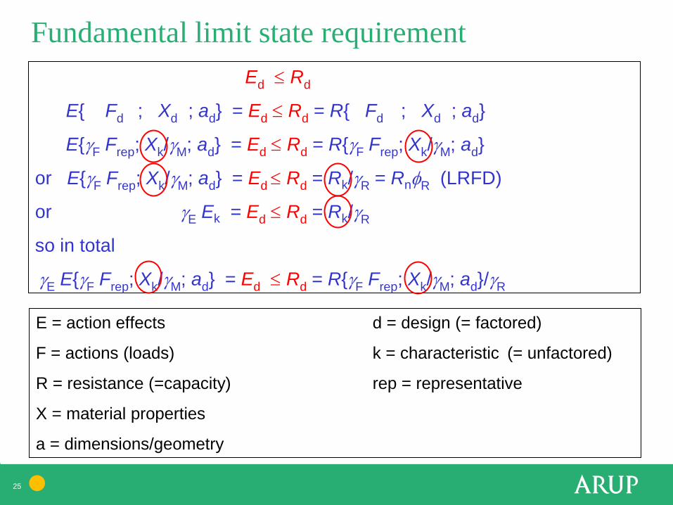
Fundamental limit state requirement Ed ≤ Rd
E{ Fd ; Xd ; ad} = Ed ≤ Rd = R{ Fd ; Xd ; ad}
E{γF Frep; Xk/γM; ad} = Ed ≤ Rd = R{γF Frep; Xk/γM; ad}
or E{γF Frep; Xk/γM; ad} = Ed ≤ Rd = Rk/γR = RnφR (LRFD)
or γE Ek = Ed ≤ Rd = Rk/γR
so in total
γE E{γF Frep; Xk/γM; ad} = Ed ≤ Rd = R{γF Frep; Xk/γM; ad}/γR
E = action effects d = design (= factored)
F = actions (loads) k = characteristic (= unfactored)
R = resistance (=capacity) rep = representative
X = material properties
a = dimensions/geometry
26
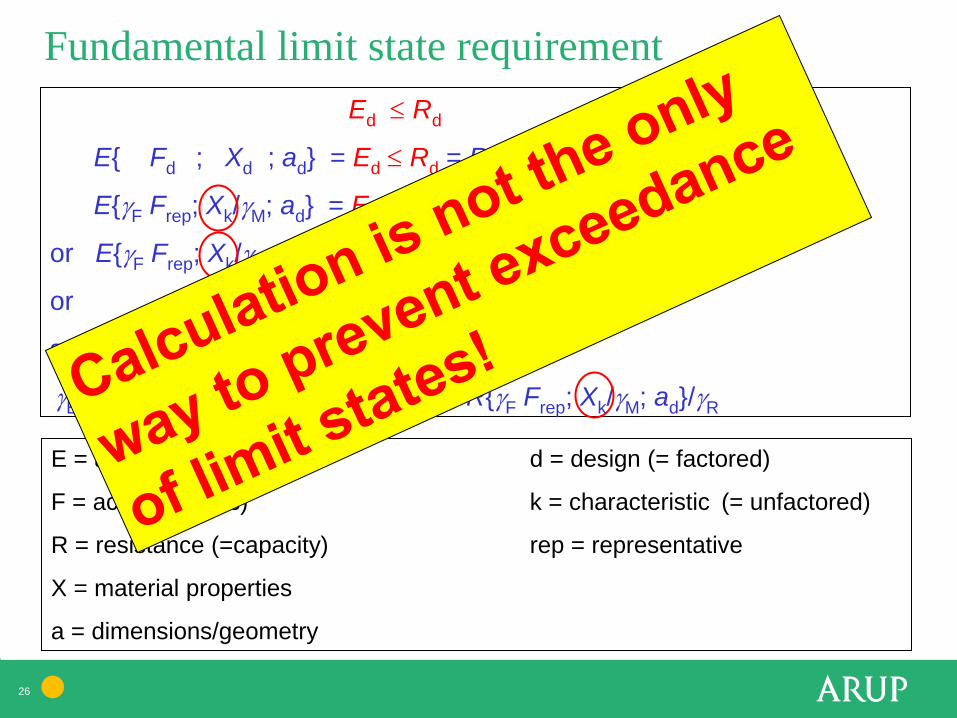
Fundamental limit state requirement Ed ≤ Rd
E{ Fd ; Xd ; ad} = Ed ≤ Rd = R{ Fd ; Xd ; ad}
E{γF Frep; Xk/γM; ad} = Ed ≤ Rd = R{γF Frep; Xk/γM; ad}
or E{γF Frep; Xk/γM; ad} = Ed ≤ Rd = Rk/γR = RnφR (LRFD)
or γE Ek = Ed ≤ Rd = Rk/γR
so in total
γE E{γF Frep; Xk/γM; ad} = Ed ≤ Rd = R{γF Frep; Xk/γM; ad}/γR
E = action effects d = design (= factored)
F = actions (loads) k = characteristic (= unfactored)
R = resistance (=capacity) rep = representative
X = material properties
a = dimensions/geometry

27
EN1990 6.3.1 Design values of actions
Load combination factors are used to avoid unreasonable coincidence of variable actions.
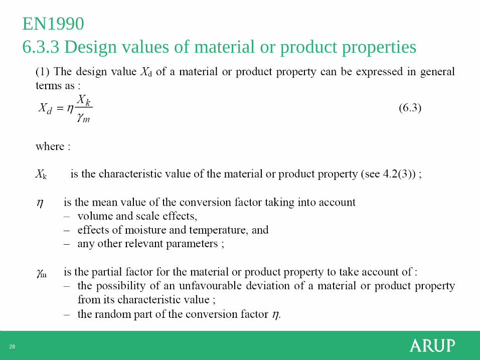
28
EN1990 6.3.3 Design values of material or product properties
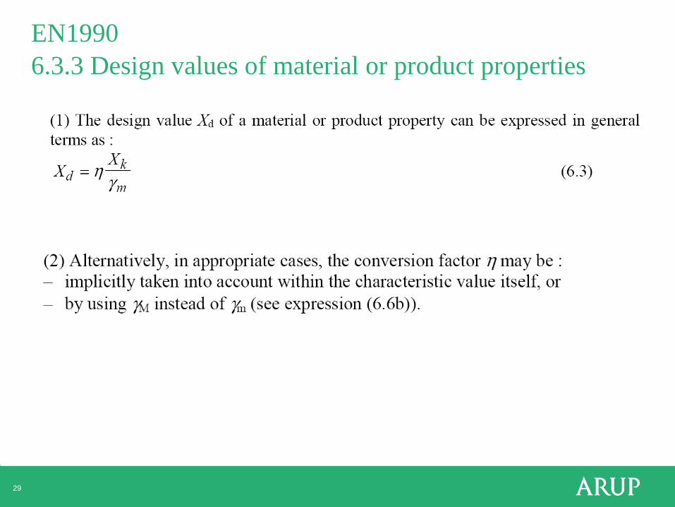
29
EN1990 6.3.3 Design values of material or product properties

30
Partial factors
For material strengths X: Design value = characteristic value / γm
Xd = Xk / γm
For “resistances” R: Rd = Rk / γR
EN1990
Concrete and steel: 2 standard deviations from the mean test result.

31
BS EN 1997-1:2004 Eurocode 7: Geotechnical design
Part 1: General rules
• 12 sections • Annexes A to J • National Annex to Part 1
Part 2: Ground investigation and testing
• 6 sections • Annexes A to X • National Annex to Part 2

32
EN 1997-1 Geotechnical design – General Rules
1 General 2 Basis of geotechnical design 3 Geotechnical data 4 Supervision of construction, monitoring and maintenance 5 Fill, dewatering, ground improvement and reinforcement 6 Spread foundations 7 Pile foundations 8 Anchorages 9 Retaining structures 10 Hydraulic failure 11 Overall stability 12 Embankments Appendices A to J
33
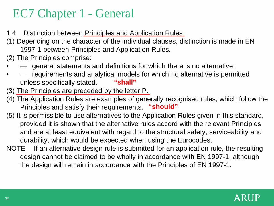
EC7 Chapter 1 - General 1.4 Distinction between Principles and Application Rules (1) Depending on the character of the individual clauses, distinction is made in EN
1997-1 between Principles and Application Rules. (2) The Principles comprise: • — general statements and definitions for which there is no alternative; • — requirements and analytical models for which no alternative is permitted
unless specifically stated. (3) The Principles are preceded by the letter P. (4) The Application Rules are examples of generally recognised rules, which follow the
Principles and satisfy their requirements. (5) It is permissible to use alternatives to the Application Rules given in this standard,
provided it is shown that the alternative rules accord with the relevant Principles and are at least equivalent with regard to the structural safety, serviceability and durability, which would be expected when using the Eurocodes.
NOTE If an alternative design rule is submitted for an application rule, the resulting design cannot be claimed to be wholly in accordance with EN 1997-1, although the design will remain in accordance with the Principles of EN 1997-1.
“shall”
“should”

34
EN 1997-1 Geotechnical design – General Rules
1 General 2 Basis of geotechnical design 3 Geotechnical data 4 Supervision of construction, monitoring and maintenance 5 Fill, dewatering, ground improvement and reinforcement 6 Spread foundations 7 Pile foundations 8 Anchorages 9 Retaining structures 10 Hydraulic failure 11 Overall stability 12 Embankments Appendices A to J

35
EN1990 3.4 Serviceability limit states
EN1990 Serviceability limit states BP87.49 BP106.15 BP111.9 BP112.11 BP124-T1.42 BP168.29
Analysis and considerations much as before: displacement, settlement, etc. Less reliance on factors of safety. Great needs and opportunities for development.

36
2.4.7 Ultimate Limit States
36
2.4.7.1 General
(1)P Where relevant, it shall be verified that the following limit states are not exceeded:
— loss of equilibrium of the structure or the ground, considered as a rigid body, in which the
strengths of structural materials and the ground are insignificant in providing resistance
(EQU);
— internal failure or excessive deformation of the structure or structural elements, including
e.g. footings, piles or basement walls, in which the strength of structural materials is
significant in providing resistance (STR);
— failure or excessive deformation of the ground, in which the strength of soil or rock is
significant in providing resistance (GEO);
— loss of equilibrium of the structure or the ground due to uplift by water pressure (buoyancy)
or other vertical actions (UPL);
— hydraulic heave, internal erosion and piping in the ground caused by hydraulic gradients
(HYD).

37
2.4.7 Ultimate limit states – STR, GEO

38
2.4.7 Ultimate Limit States
38
2.4.7.1 General
(1)P Where relevant, it shall be verified that the following limit states are not exceeded:
— loss of equilibrium of the structure or the ground, considered as a rigid body, in which the
strengths of structural materials and the ground are insignificant in providing resistance
(EQU);
— internal failure or excessive deformation of the structure or structural elements, including
e.g. footings, piles or basement walls, in which the strength of structural materials is
significant in providing resistance (STR);
— failure or excessive deformation of the ground, in which the strength of soil or rock is
significant in providing resistance (GEO);
— loss of equilibrium of the structure or the ground due to uplift by water pressure (buoyancy)
or other vertical actions (UPL);
— hydraulic heave, internal erosion and piping in the ground caused by hydraulic gradients
(HYD).
a a
W W
M
F1 F2
b
39
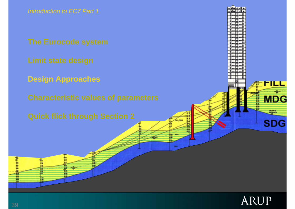
Introduction to EC7 Part 1
The Eurocode system
Limit state design
Design Approaches
Characteristic values of parameters
Quick flick through Section 2

40
Fundamental limit state requirement Ed ≤ Rd
E{ Fd ; Xd ; ad} = Ed ≤ Rd = R{ Fd ; Xd ; ad}
E{γF Frep; Xk/γM; ad} = Ed ≤ Rd = R{γF Frep; Xk/γM; ad}
or E{γF Frep; Xk/γM; ad} = Ed ≤ Rd = Rk/γR = RnφR (LRFD)
or γE Ek = Ed ≤ Rd = Rk/γR
so in total
γE E{γF Frep; Xk/γM; ad} = Ed ≤ Rd = R{γF Frep; Xk/γM; ad}/γR
E = action effects d = design (= factored)
F = actions (loads) k = characteristic (= unfactored)
R = resistance (=capacity) rep = representative
X = material properties
a = dimensions/geometry

41
2.4.7 Ultimate Limit States

42
2.4.7.3.3 Design resistances
2.4.7.3.3 Design resistances
(1) Partial factors may be applied either to ground properties (X) or resistances (R) or to both, as follows:
Rd = R{γF Frep; Xk/γM; ad} (2.7a)
or
Rd = R{γF Frep; Xk; ad}/γR (2.7b)
or
Rd = R{γF Frep; Xk/γM; ad}/γR (2.7c)
γE E{γF Frep; Xk/γM; ad} = Ed ≤ Rd = R{γF Frep; Xk/γM; ad}/γR
Three different “Design Approaches”

43
Annex A - Partial and correlation factors for ultimate limit states and recommended values
Values recommended by the code drafters, but each nation may specify own values.

44
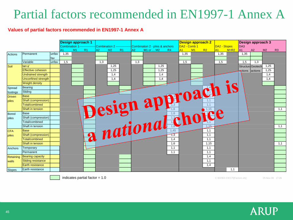
Partial factors recommended in EN1997-1 Annex A Values of partial factors recommended in EN1997-1 Annex A
Design approach 1 Design approach 2 Design approach 3Combination 1-----------------Combination 2 ----------------Combination 2 - piles & anchors DA2 - Comb 1 DA2 - Slopes DA3A1 M1 R1 A2 M2 R1 A2 M1 or … M2 R4 A1 M1 R2 A1 M=R2 A1 A2 M2 R3
Actions unfav 1,35 1,35 1,35 1,35favunfav 1,5 1,3 1,3 1,5 1,5 1,5 1,3
Soil tan φ' 1,25 1,25 StructuraGeotech 1,25Effective cohesion 1,25 1,25 actions actions 1,25Undrained strength 1,4 1,4 1,4Unconfined strength 1,4 1,4 1,4Weight density
Spread Bearing 1,4footings Sliding 1,1Driven Base 1,3 1,1piles Shaft (compression) 1,3 1,1
Total/combined 1,3 1,1Shaft in tension 1,25 1,6 1,15 1,1
Bored Base 1,25 1,6 1,1piles Shaft (compression) 1,0 1,3 1,1
Total/combined 1,15 1,5 1,1Shaft in tension 1,25 1,6 1,15 1,1
CFA Base 1,1 1,45 1,1piles Shaft (compression) 1,0 1,3 1,1
Total/combined 1,1 1,4 1,1Shaft in tension 1,25 1,6 1,15 1,1
Anchors Temporary 1,1 1,1 1,1Permanent 1,1 1,1 1,1
Retaining Bearing capacity 1,4walls Sliding resistance 1,1
Earth resistance 1,4Slopes Earth resistance 1,1
indicates partial factor = 1.0 C:\BX\BX-C\EC7\[Factors.xls] 25-Nov-06 17:26
Permanent
Variable
45
Partial factors recommended in EN1997-1 Annex A Values of partial factors recommended in EN1997-1 Annex A
Design approach 1 Design approach 2 Design approach 3Combination 1-----------------Combination 2 ----------------Combination 2 - piles & anchors DA2 - Comb 1 DA2 - Slopes DA3A1 M1 R1 A2 M2 R1 A2 M1 or … M2 R4 A1 M1 R2 A1 M=R2 A1 A2 M2 R3
Actions unfav 1,35 1,35 1,35 1,35favunfav 1,5 1,3 1,3 1,5 1,5 1,5 1,3
Soil tan φ' 1,25 1,25 StructuraGeotech 1,25Effective cohesion 1,25 1,25 actions actions 1,25Undrained strength 1,4 1,4 1,4Unconfined strength 1,4 1,4 1,4Weight density
Spread Bearing 1,4footings Sliding 1,1Driven Base 1,3 1,1piles Shaft (compression) 1,3 1,1
Total/combined 1,3 1,1Shaft in tension 1,25 1,6 1,15 1,1
Bored Base 1,25 1,6 1,1piles Shaft (compression) 1,0 1,3 1,1
Total/combined 1,15 1,5 1,1Shaft in tension 1,25 1,6 1,15 1,1
CFA Base 1,1 1,45 1,1piles Shaft (compression) 1,0 1,3 1,1
Total/combined 1,1 1,4 1,1Shaft in tension 1,25 1,6 1,15 1,1
Anchors Temporary 1,1 1,1 1,1Permanent 1,1 1,1 1,1
Retaining Bearing capacity 1,4walls Sliding resistance 1,1
Earth resistance 1,4Slopes Earth resistance 1,1
indicates partial factor = 1.0 C:\BX\BX-C\EC7\[Factors.xls] 25-Nov-06 17:26
Permanent
Variable

46
Source: Andrew Bond, chair of SC7

47
Partial factors for DA1 – UK National Annex B
Design approach 1 Combination 1---------------- Combination 2 ----------------Combination 2 - piles & anchorsA1 M1 R1 A2 M2 R1 A2 M1 or … M2 R4
Actions unfav 1,35favunfav 1,5 1,3 1,3
Soil tan φ' 1,25 1,25Effective cohesion 1,25 1,25Undrained strength 1,4 1,4Unconfined strength 1,4 1,4Weight density
Spread Bearing EC7footings Sliding valuesDriven Base 1,7/1.5 1,3piles Shaft (compression) 1.5/1.3 1,3
Total/combined 1.7/1.5 1,3Shaft in tension 2.0/1.7 1.6
Bored Base 2.0/1.7 1,6piles Shaft (compression) 1.6/1.4 1,3
Total/combined 2.0/1.7 1.5Shaft in tension 2.0/1.7 1.6
CFA Base As 1.45piles Shaft (compression) for 1.3
Total/combined bored 1.4Shaft in tension piles 1.6
Anchors Temporary 1,1 1,1Permanent 1,1 1,1
Retaining Bearing capacitywalls Sliding resistance
Earth resistanceSlopes Earth resistance
indicates partial factor = 1.0
C:\BX\BX-C\EC7\[Factors.xls]
Permanent
Variable
• More consistent across a wide range of geotechnical situations, which might overlap.
• Good for numerical analysis.

48
Approaches to ULS design – The merits of
Design Approach 1 in Eurocode 7 Brian Simpson
Arup Geotechnics BP145a.1 BP168.83
ISGSR2007 - First International Symposium on Geotechnical Safety and Risk
49 ©
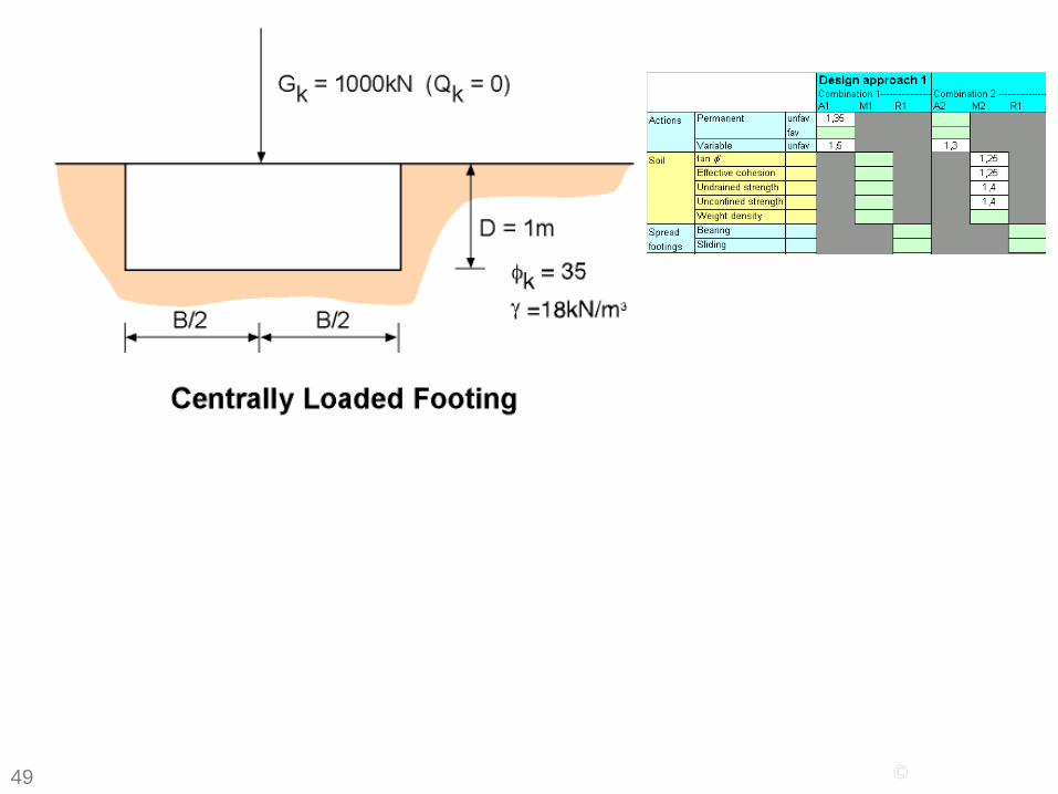
Footing BP72.45 BP106.53 BP111.27 BP124-A2.18 BP168-2.36
Combination 2
Comb1
Combination 1
Combination 2

50
Annex D (informative) A sample analytical method for bearing resistance calculation
Figure D.1 — Notations

51 ©
Footing BP72.45 BP106.53 BP111.27 BP124-A2.18 BP168-2.36
Combination 2
Comb1
Combination 1
Combination 2
Combination 2 Comb1
Combination 1 B = 1.06m M = 179 kNm
Combination 2 B = 1.31m M = 164 kNm
Combination 2 with Combination 1 loads:
B = 1.31m M = 221 kNm

52 ©
Footing BP72.45 BP106.53 BP111.27 BP124-A2.18 BP168-2.37 DA2 DA3
1000 10001.35 1.35
0 01.5 1.535 351 1.25
0 01 1.25
1.4 1 18 18 18 18
25 25
1.23 1.5
1392 1401 0 0
35.0 29.3 0 0
33.3 16.946.1 28.445.2 17.8
1.00 1.001.00 1.001.00 1.00
1.57 1.490.70 0.701.59 1.52
1957 13991398 1399
1.23 1.50
214 263 1.77 2.65
Char DA1-1 DA1-2 DA1
Vk kN 1000 1000 1000γV 1 1.35 1Hk kN 0 0 0γH 1 1.5 1.3φ 35 35 35γ−φ 1 1 1.25c kPa 0 0 0γ-c 1 1 1.25γ-R 1 1 1q kPa 18 18 18γ kN/m3 18 18 18γ-cct kN/m3 25 25 25
B (guess) m 0.92 1.06 1.31
Incl footing Vd kPa 1023 1386 1033 1386Hd kPa 0 0 0phi-d 35.0 35.0 29.3c-d kPa 0 0 0
Nq 33.3 33.3 16.9Nc 46.1 46.1 28.4Ng 45.2 45.2 17.8
iq 1.00 1.00 1.00ig 1.00 1.00 1.00ic 1.00 1.00 1.00
sq 1.57 1.57 1.49sg 0.70 0.70 0.70sc 1.59 1.59 1.52
R 1020 1399 1031Rd 1020 1399 1031
B-req 0.92 1.05 1.31 1.31
Md 115 179 164 221BC FOS 1.00 1.31 2.03 2.03
C:\BX\BX-C\EC7\[EC7.xls]

53
DA1, 2 and 3 – comparisons for square footing
0
50
100
150
200
250
300
Char DA1-1 DA1-2 DA1 DA2 DA3
Width cm
Md kNm/m
54 ©
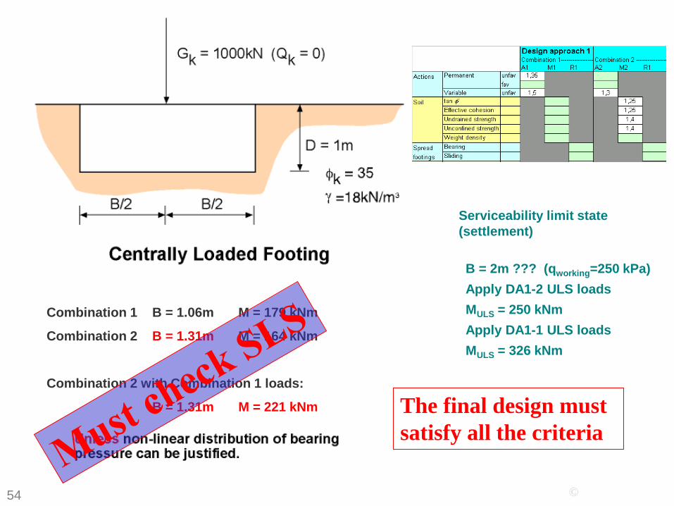
Footing BP72.45 BP106.53 BP111.27 BP124-A2.18 BP168-2.36
Combination 2
Comb1
Combination 1
Combination 2
Combination 2 Comb1
Combination 1 B = 1.06m M = 179 kNm
Combination 2 B = 1.31m M = 164 kNm
Combination 2 with Combination 1 loads:
B = 1.31m M = 221 kNm
Serviceability limit state (settlement)
B = 2m ??? (qworking=250 kPa) Apply DA1-2 ULS loads MULS = 250 kNm Apply DA1-1 ULS loads MULS = 326 kNm
The final design must satisfy all the criteria

55
Introduction to EC7 Part 1 The Eurocode system Limit state design Design Approaches Characteristic values of parameters Quick flick through Section 2

56
Fundamental limit state requirement Ed ≤ Rd
E{ Fd ; Xd ; ad} = Ed ≤ Rd = R{ Fd ; Xd ; ad}
E{γF Frep; Xk/γM; ad} = Ed ≤ Rd = R{γF Frep; Xk/γM; ad}
or E{γF Frep; Xk/γM; ad} = Ed ≤ Rd = Rk/γR = RnφR (LRFD)
or γE Ek = Ed ≤ Rd = Rk/γR
so in total
γE E{γF Frep; Xk/γM; ad} = Ed ≤ Rd = R{γF Frep; Xk/γM; ad}/γR
E = action effects d = design (= factored)
F = actions (loads) k = characteristic (= unfactored)
R = resistance (=capacity) rep = representative
X = material properties
a = dimensions/geometry

57
Characteristic values in EC7

58
Characteristic values in EC7 – definition (2.4.5.2)

59
Characteristic values in EC7
2.4.3(4) also mentions:

60
EN1990 6.3.3 Design values of material or product properties
61
Characteristic values in EC7

62
Characteristic values in EC7 – zone of ground
“Cautious” – worse than most probable.
Small building on estuarine beds near slope

63
Characteristic values in EC7 – zone of ground

64
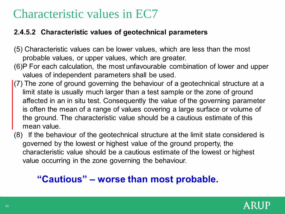
Characteristic values in EC7 – zone of ground 2.4.5.2 Characteristic values of geotechnical parameters
Thoughtful interpretation – not simple averaging

65
Characteristic values in EC7 – definition (2.4.5.2)

66
Characteristic values in EC7 • NOT a fractile of the results of particular, specified laboratory tests on
specimens of material.
• A cautious estimate of the value affecting the occurrence of the limit state
• Take account of time effects, brittleness, soil fabric and structure, the effects of construction processes and the extent of the body of ground involved in a limit state
• The designer’s expertise and understanding of the ground are all encapsulated in the characteristic value
• Consider both project-specific information and a wider body of geotechnical knowledge and experience.
• Characteristic = moderately conservative = representative (BS8002) = what good designers have always done.

71
0.5 SD below the mean? A suggestion:
When:
• a limit state depends on the value of a parameter averaged over a large amount of ground (ie a mean value), and
• the ground property varies in a homogeneous, random manner, and
• at least 10 test values are available
Then: A value 0.5SD below the mean of the test results provides a useful indication of the characteristic value
(Contribution to Discussion Session 2.3, XIV ICSMFE, Hamburg. Balkema., Schneider H R (1997) Definition and determination of characteristic soil properties. Discussion to ISSMFE Conference, Hamburg.)

72
0.5 SD below the mean? - a useful consideration, not a rule
C:\bx\EC7\[EC7.xls] 26-May-03 10:10
0
0.2
0.4
0.6
0.8
1
1.2
-3 -2.5 -2 -1.5 -1 -0.5 0 0.5 1
5% fractile of test resuts
5% fractile of mean values
Results of soil tests
Mean SD from mean
More remote when dependent on specific small zone.
73
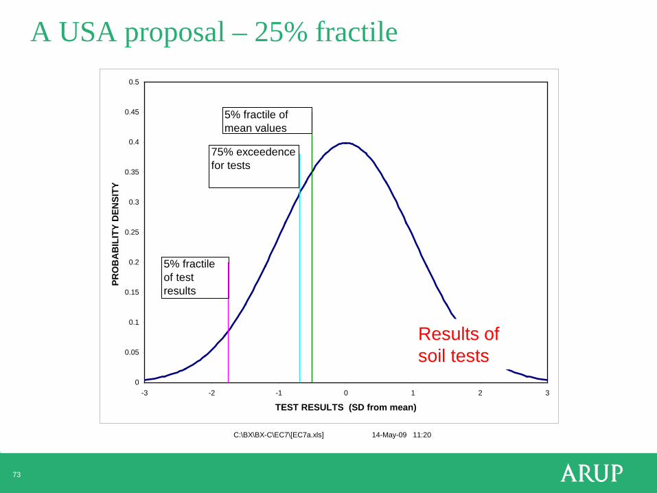
A USA proposal – 25% fractile
C:\BX\BX-C\EC7\[EC7a.xls] 14-May-09 11:20
0
0.05
0.1
0.15
0.2
0.25
0.3
0.35
0.4
0.45
0.5
-3 -2 -1 0 1 2 3
TEST RESULTS (SD from mean)
PRO
BA
BIL
ITY
DEN
SITY
5% fractile of test results
5% fractile of mean values
75% exceedence for tests
Results of soil tests

Angle of shearing resistance φ’
σ’
τ
c’ ?

φ’ – peak, critical state or residual?
Residual
• The value that will prevent the exceedance of the limit state. • Caution about progressive loss of density or strength. • So caution about φ’>38º. • Suggestion: The ULS design value of the shear strength should never be greater
than a cautious (ie “characteristic”) estimate of the critical state strength of the material.
• Interfaces between structure and ground (wall friction, sliding etc) – use critical state value as characteristic value, and apply normal factors.
• Useful guidance in BS8002 (“withdrawn”)

φ’ – peak, critical state or residual?
• Useful guidance in BS8002 (“withdrawn”)
Critical state

Data from more than one source
Bored pile

Conflicting data
The code drafters could not have known about this uncertainty

79
Eurocode 7 – fundamental issues and some implications for users.
BP145a.1 BP168.83
Nordic Geotechnical Conference, Copenhagen, July 2012

80
Introduction to EC7 Part 1 The Eurocode system Limit state design Design Approaches Characteristic values of parameters Quick flick through Section 2

81
EN 1997-1 Geotechnical design – General Rules
1 General 2 Basis of geotechnical design 3 Geotechnical data 4 Supervision of construction, monitoring and maintenance 5 Fill, dewatering, ground improvement and reinforcement 6 Spread foundations 7 Pile foundations 8 Anchorages 9 Retaining structures 10 Hydraulic failure 11 Overall stability 12 Embankments Appendices A to J

82
EC7 Section 2 - Basis of geotechnical design
2.1 Design requirements 2.2 Design situations 2.3 Durability 2.4 Geotechnical design by calculation 2.5 Design by prescriptive measures 2.6 Load tests and tests on experimental models 2.7 Observational method 2.8 Geotechnical Design Report

83
EC7 Section 2 - Basis of geotechnical design
2 Basis of geotechnical design 2.1 Design requirements (1)P For each geotechnical design situation it shall be verified that no relevant limit state, as defined in EN 1990:2002, is exceeded.

84
Design situations

85
Design situations

86
EC7 Section 2 - Basis of geotechnical design
2.1 Design requirements 2.2 Design situations 2.3 Durability 2.4 Geotechnical design by calculation 2.5 Design by prescriptive measures 2.6 Load tests and tests on experimental models 2.7 Observational method 2.8 Geotechnical Design Report

87
2.5 Design by prescriptive measures

88
2.6 Load tests and tests on experimental models
89
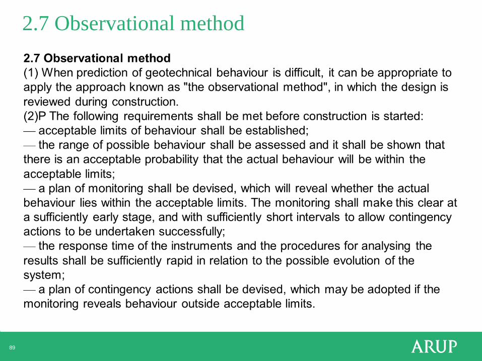
2.7 Observational method

90
2.7 Observational method

91 ©
BP87.84 BP124-T1.80
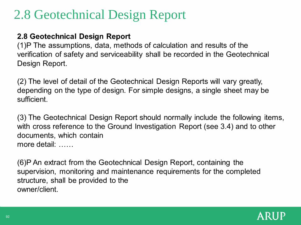
92
2.8 Geotechnical Design Report

Simpson, B & Driscoll, R (1998) Eurocode 7 - a commentary. Construction Research Communications Ltd, Watford, UK. Orr TLL & Farrell E R (1999) Geotechnical design to Eurocode 7. Springer-Verlag. Gulvanessian, H, Calgaro, J-A, Holicky, M (2002) Designers' Guide to EN 1990 - Eurocode: Basis of structural design. Thomas Telford. Frank, R, Bauduin, C, Driscoll, R, Kavvadas, M, Krebs Ovesen, N, Orr, T and Schuppener, B (2004) Designers' Guide to EN 1997-1 - Eurocode 7: Geotechnical design - General rules. Thomas Telford, London. Communities and Local Government (2007) A Designers’ Simple Guide to BS EN 1997. Department for Communities and Local Government: London. Driscoll, R, Scott, P & Powell, J (2008) EC7 – implications for UK practice. CIRIA Report C641. Bond, A and Harris, A (2008) Decoding Eurocode 7. Taylor and Francis, London. New from BSI
Concise EC7 Eurocodes Plus
EC7 commentaries BP68.6 BP124-T4.7 BP168-3.44

EC7 commentaries BP68.6 BP124-T4.7 BP168-3.44
Simpson, B & Driscoll, R (1998) Eurocode 7 - a commentary. Construction Research Communications Ltd, Watford, UK. Orr TLL & Farrell E R (1999) Geotechnical design to Eurocode 7. Springer-Verlag. Gulvanessian, H, Calgaro, J-A, Holicky, M (2002) Designers' Guide to EN 1990 - Eurocode: Basis of structural design. Thomas Telford. Frank, R, Bauduin, C, Driscoll, R, Kavvadas, M, Krebs Ovesen, N, Orr, T and Schuppener, B (2004) Designers' Guide to EN 1997-1 - Eurocode 7: Geotechnical design - General rules. Thomas Telford, London. Communities and Local Government (2007) A Designers’ Simple Guide to BS EN 1997. Department for Communities and Local Government: London. Driscoll, R, Scott, P & Powell, J (2008) EC7 – implications for UK practice. CIRIA Report C641. Bond, A and Harris, A (2008) Decoding Eurocode 7. Taylor and Francis, London. New from BSI
Concise EC7 Eurocodes Plus

95
Introduction to EC7 Part 1 The Eurocode system Limit state design Design Approaches Characteristic values of parameters Quick flick through Section 2
Thanks for your attention.