25 common things you can do with an … common things you can do with an arbitrary/function...
TRANSCRIPT

25 Common Things You Can Do With an Arbitrary/Function Generator

Page 2
www.tektronix.com/AFG3000
Introduction......................................................................................................... 3
Embedded and Semiconductor Test Applications ............................................................. 4 1. Clock Source............................................................................................................................ 4 2. Characterization of Logic Devices - Timing Margin Test .......................................................... 5 3. Characterize Phase Locked Loop (PLL) Circuits...................................................................... 6 4. Characterizing Operational Amplifiers...................................................................................... 7 5. Timing Margin Test of AFE (Analog Front End) for CCD Sensor ............................................. 8 6. Characterizing CCD Sensor – Delay Margin Test .................................................................... 9 7. Testing Audio DAC ................................................................................................................ 10 8. DC Power Supply Test........................................................................................................... 11
RF Related Applications ..........................................................................................12 9. Measure Frequency Response of Bandpass Filter................................................................. 12 10. Measure Intermodulation Distortion of RF Components......................................................... 13 11. Pulsed Noise-Figure Measurement........................................................................................ 14 12. Functional Test of RFID Receiver ICs.................................................................................... 15 13. EMC Radiation Testing .......................................................................................................... 16 14. Characterizing I/Q Modulators ............................................................................................... 17
Education-Related Applications.................................................................................18 15. Measure Frequency Response of Bandpass Filter................................................................. 18 16. AM/FM Radio Test and Alignment ......................................................................................... 19
Automotive Applications .........................................................................................20 17. Test & Optimization of Engine Control Units .......................................................................... 20 18. Simulation of Automotive Sensor Signals............................................................................... 21 19. Characterize and optimize Power MOSFET circuitry in Automotive Electronics..................... 22 20. Analyzing Switching Waveforms of IGBT circuitry .................................................................. 23
Medical Applications..............................................................................................24 21. Testing Pacemakers, Cardioverter Defibrillators, and other Implantable Medical Devices ..... 24 22. Testing Medical Ultrasound Equipment.................................................................................. 25 23. Testing Detector Circuit of Medical Ultrasound Equipment .................................................... 26
Industrial Applications............................................................................................27 24. Characterizing Dynamic Performance of Hydraulic Servo Valves .......................................... 27
Research Applications ............................................................................................28 25. Driving and Modulating Laser Diodes .................................................................................... 28
Tektronix AFG3000 Series Arbitrary/Function Generators ..................................................29 The Next Generation of Signal Generation...................................................................................... 29

Page 3
www.tektronix.com/AFG3000
Introduction An acquisition instrument — usually an oscilloscope or logic analyzer — is probably the first thing that comes to mind when you think about making electronic measurements. But these tools can only make a measurement when they are able to acquire a signal of some kind. And there are many instances in which no such signal is available unless it is externally provided.
A strain gauge amplifier, for example, does not produce signals; it merely increases the power of the signals it receives from a sensor. Inevitably it becomes necessary to test the amplifier before it is connected to the circuit that feeds it. In order to use an acquisition instrument to measure the behavior of such devices, you must provide a stimulus signal at the input.
To cite another example, engineers must characterize their emerging designs to ensure that the new hardware meets design specifications across the full range of operating conditions and beyond. This is known as margin or limit testing. It is a measurement task that requires a complete solution; one that can generate signals as well as make measurements.
The signal generator pairs with an acquisition instrument such as an oscilloscope or spectrum analyzer to create a complete measurement solution. In its various configurations, the signal generator can provide stimulus signals in the form of analog waveforms, pulse patterns, modulation, intentional distortion, noise, and more. To make effective design, characterization, or troubleshooting measurements, it is important to consider both elements of the solution.
The arbitrary/function generator (AFG) serves a wide range of stimulus needs; in fact, it is the prevailing signal generator architecture in the industry today. If the DUT requires the classic sine and square waveforms (to name a few) and the ability to switch almost instantly between two frequencies, the arbitrary/function generator (AFG) is the right tool. An additional virtue is the AFG’s low cost, which makes it very attractive for applications that do not require an AWG’s versatility.
The AFG offers unique strengths: it produces stable waveforms in standard shapes such as sine, square, pulse, triangle, and others. In addition, it allows users to generate so called arbitrary waveforms with a shape defined by the user. Moreover, AFGs offer a way to modulate the signal from internal or external sources, generate frequency sweeps or output signal bursts.
Waveforms can be created in a variety ways, the choice of which depends upon the information available about the DUT and its input requirements; whether there is a need to add distortion or error signals, and other variables.
o Create: Customer defined signals for circuit stimulus and testing.
o Replicate: Synthesize a real-world signal unavailable in the electronics lab (previously captured from an oscilloscope).
o Generate: Ideal or stressed reference signals for industry standards with specific tolerances.

Page 4
www.tektronix.com/AFG3000
Embedded and Semiconductor Test Applications
1. Clock Source
What for Frequency margining: Test clock frequency operating range of digital circuits.
Substitute unavailable clock source for functional test of device.
Who for Electronic test and design engineers who develop embedded and digital
communication circuitry.
Benefits of using an Arbitrary/Function Generator Cost savings over dedicated pulse generators. Dual channels and floating outputs to generate differential signals. Pulse and square frequency range up to 120 MHz.
Tips and Hints Differential clock signals, e.g. for PECL, LVPECL or LVDS, can be generated
with a dual channel source with floating single-ended outputs. To generate a differential signal, configure waveform, frequency and amplitude in
Channel 1 and duplicate inverted settings to Channel 2 via the CH1 Complement function. Then activate the synchronization mode by setting Frequency CH1=CH2 to On and initiating Align Phase.
Disable any on-board clock source while driving the device with an external clock source.
To avoid signal integrity degradations such as ringing or variable delay and amplitude, take care to obtain adequate impedance matching between the probe connecting to the signal source and the board trace.
DigitalCircuit
HardwareMonitor
* Recommended models: Tektronix AFG3251 or AFG3252
Page 5
www.tektronix.com/AFG3000
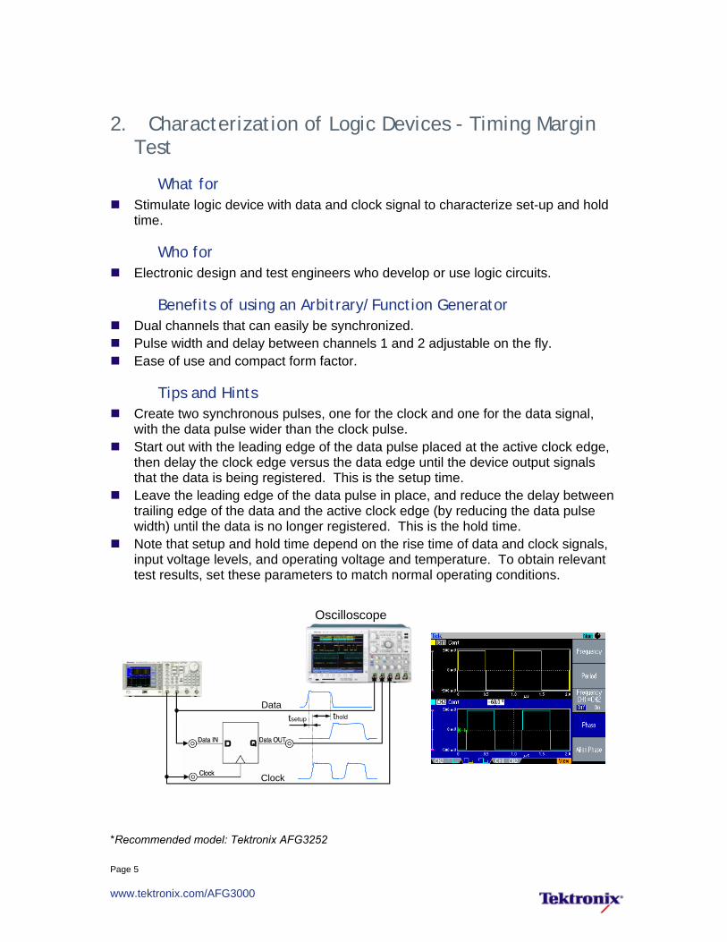
2. Characterization of Logic Devices - Timing Margin Test
What for Stimulate logic device with data and clock signal to characterize set-up and hold
time.
Who for Electronic design and test engineers who develop or use logic circuits.
Benefits of using an Arbitrary/Function Generator Dual channels that can easily be synchronized. Pulse width and delay between channels 1 and 2 adjustable on the fly. Ease of use and compact form factor.
Tips and Hints Create two synchronous pulses, one for the clock and one for the data signal,
with the data pulse wider than the clock pulse. Start out with the leading edge of the data pulse placed at the active clock edge,
then delay the clock edge versus the data edge until the device output signals that the data is being registered. This is the setup time.
Leave the leading edge of the data pulse in place, and reduce the delay between trailing edge of the data and the active clock edge (by reducing the data pulse width) until the data is no longer registered. This is the hold time.
Note that setup and hold time depend on the rise time of data and clock signals, input voltage levels, and operating voltage and temperature. To obtain relevant test results, set these parameters to match normal operating conditions.
Data
Clock
tsetup thold
Oscilloscope
*Recommended model: Tektronix AFG3252
Page 6
www.tektronix.com/AFG3000
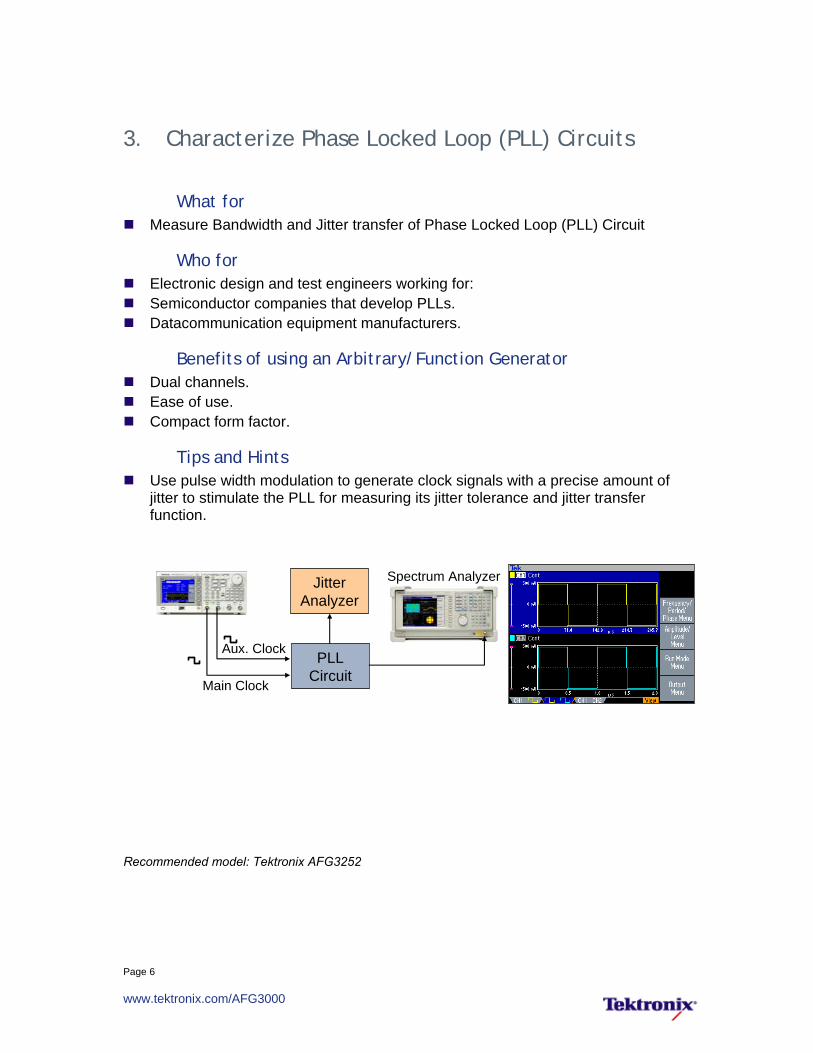
3. Characterize Phase Locked Loop (PLL) Circuits
What for Measure Bandwidth and Jitter transfer of Phase Locked Loop (PLL) Circuit
Who for Electronic design and test engineers working for: Semiconductor companies that develop PLLs. Datacommunication equipment manufacturers.
Benefits of using an Arbitrary/Function Generator Dual channels. Ease of use. Compact form factor.
Tips and Hints Use pulse width modulation to generate clock signals with a precise amount of
jitter to stimulate the PLL for measuring its jitter tolerance and jitter transfer function.
Recommended model: Tektronix AFG3252
PLLCircuit
Aux. Clock
Main Clock
Spectrum AnalyzerJitterAnalyzer
Page 7
www.tektronix.com/AFG3000
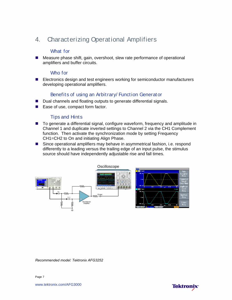
4. Characterizing Operational Amplifiers
What for Measure phase shift, gain, overshoot, slew rate performance of operational
amplifiers and buffer circuits.
Who for Electronics design and test engineers working for semiconductor manufacturers
developing operational amplifiers.
Benefits of using an Arbitrary/Function Generator Dual channels and floating outputs to generate differential signals. Ease of use, compact form factor.
Tips and Hints To generate a differential signal, configure waveform, frequency and amplitude in
Channel 1 and duplicate inverted settings to Channel 2 via the CH1 Complement function. Then activate the synchronization mode by setting Frequency CH1=CH2 to On and initiating Align Phase.
Since operational amplifiers may behave in asymmetrical fashion, i.e. respond differently to a leading versus the trailing edge of an input pulse, the stimulus source should have independently adjustable rise and fall times.
Oscilloscope
Recommended model: Tektronix AFG3252

Page 8
www.tektronix.com/AFG3000
5. Timing Margin Test of AFE (Analog Front End) for CCD Sensor
What for Determine sensitivity of AFE to falling edge time of input signal.
Who for Electronic design engineers who work on CCD sensor designs at semiconductor
and electronics companies that develop digital imaging products.
Benefits of using AFG3252 Pulse frequency up to 120 MHz. Rising and falling pulse edge times adjustable independently. Waveform parameter adjustments take immediate effect without interrupting test.
Tips and Hints Set the generator's load impedance setting to match the impedance of the
connected circuit so that the amplitude will display accurately. To isolate the AFE's sensitivity to trailing edge variations, only adjust the trailing
edge time and hold the leading edge time constant.
Recommended model: Tektronix AFG3252
Page 9
www.tektronix.com/AFG3000
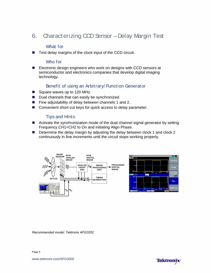
6. Characterizing CCD Sensor – Delay Margin Test
What for Test delay margins of the clock input of the CCD circuit.
Who for Electronic design engineers who work on designs with CCD sensors at
semiconductor and electronics companies that develop digital imaging technology.
Benefit of using an Arbitrary/Function Generator Square waves up to 120 MHz. Dual channels that can easily be synchronized. Fine adjustability of delay between channels 1 and 2. Convenient short-cut keys for quick access to delay parameter.
Tips and Hints Activate the synchronization mode of the dual channel signal generator by setting
Frequency CH1=CH2 to On and initiating Align Phase. Determine the delay margin by adjusting the delay between clock 1 and clock 2
continuously in fine increments until the circuit stops working properly.
Recommended model: Tektronix AFG3252

Page 10
www.tektronix.com/AFG3000
7. Testing Audio DAC
What for Functional test of audio ADC and DAC. Evaluate clock frequency operating range of audio ADC and DAC.
Who for Electronic design engineers working in semiconductor companies that design
audio ADCs and DACs.
Benefit of using an Arbitrary/Function Generator Dual channels that can operate with independent timing. Good noise and jitter specifications.
Tips and Hints To drive the DAC clock and control the audio generator with a dual channel
arbitrary/function generator, channels 1 and 2 must run in 'unsynchronized' mode.
Disable any clock source on the DAC test board while driving the device with an external clock source.
Set the generator's load impedance setting to match the impedance of the connected circuit so that the amplitude will display accurately.
Control Signal
DigitalAudio
GeneratorDAC
Clock
AudioSignal
Analyzer
Recommended model: Tektronix AFG3252

Page 11
www.tektronix.com/AFG3000
8. Immunity from Power Supply Disturbances
What for Evaluate performance and immunity of electronic systems (PC motherboard,
automotive electronic device, etc.) to power cycling, transients and disturbances in power supply.
Who for Electronic design engineers designing computers, peripherals, embedded
systems, or automotive electronics.
Benefits of using an Arbitrary/Function Generator Powerful waveform creation and editing capability of ArbExpress™ software. Ease of use and compact form factor of instrument.
Tips and Hints Configure the generator's load impedance setting to match the impedance of the
connected circuit so that the amplitude will display accurately. If shape of test waveform is prescribed as time and amplitude values, enter them
in ArbExpress via Point Draw Table.
DCPowerSupply
ElectronicCircuit
+
–
HardwareMonitor
Recommended models: Tektronix AFG3000 Series

Page 12
www.tektronix.com/AFG3000
RF Related Applications 9. Measure Frequency Response of Bandpass Filter
What for Stimulate filter with swept sinewave and measure filter’s frequency response with
spectrum analyzer.
Who for Electronic design engineers working for filter vendors or wireless communication
equipment vendors. Professors, lab managers working in student labs and universities.
Benefits of using an Arbitrary/Function Generator Ease of use. Large screen shows all relevant waveform and sweep parameters at a single
glance for full confidence in correct settings. Compact form factor leaves more room on the bench for device and cables.
Tips and Hints If only an oscilloscope is available, and no spectrum analyzer, trigger on the
sweep start via the generator's trigger output, set the oscilloscope's time scale to match the generator's sweep time and interpret it as frequency values.
Bandpass Filter
Spectrum Analyzer
Recommended model: Tektronix AFG3000 Series

Page 13
www.tektronix.com/AFG3000
10. Measure Intermodulation Distortion of RF Components
What for Stimulate RF components with dual tone to measure second and third order
intermodulation distortion with a spectrum analyzer.
Who for Electronic design engineers designing or using RF amplifiers, gain blocks,
mixers, modulators, connectors, splitters, couplers, relays, attenuators, PIN diodes, carbon resistors, coaxial cable, and others.
Benefits of using an Arbitrary/Function Generator Eliminates need for mixer to combine multiple signals. Ease of use reduces set-up time. Compact form factor saves room on the bench.
Tips and Hints Create dual tone conveniently by creating each tone individually in ArbExpress
and then adding them via waveform math. To avoid waveform discontinuities, define both tones with an integer number of
waveform cycles.
RF Component
Dual tone
Spectrum Analyzer
Recommended model: Tektronix AFG3252

Page 14
www.tektronix.com/AFG3000
11. Pulsed Noise-Figure Measurement
What for AFG3252 generates two synchronous pulse signals to power up RF amplifier and
trigger noise figure measurement on spectrum analyzer.
Who for RF design and test engineers developing components and systems for wireless
communications for burst-type standards (TDMA, GSM, …), as well as radar and electronic warfare.
Benefits of using an Arbitrary/Function Generator Dual channels that can easily be synchronized. Ease of use. Saves cost and bench space compared to dedicated pulse generators.
Tips and Hints So that the spectrum analyzer measures the amplifier response during the
switch-on phase, activate the synchronization mode of the dual channel signal generator by setting Frequency CH1=CH2 to On and initiating Align Phase.
Match the amplitude in Channel 1 to the bias level of the amplifier. Match the amplitude in Channel 2 to the trigger input of the spectrum analyzer.
Recommended model: Tektronix AFG3252
Page 15
www.tektronix.com/AFG3000
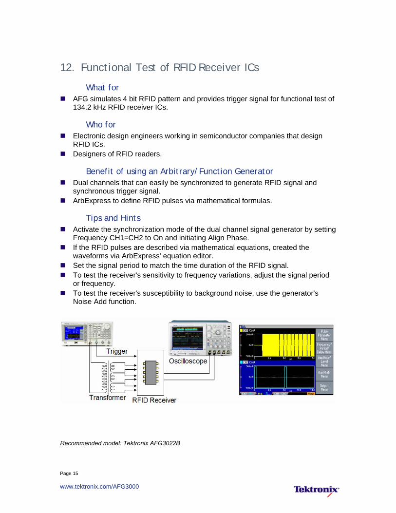
12. Functional Test of RFID Receiver ICs
What for AFG simulates 4 bit RFID pattern and provides trigger signal for functional test of
134.2 kHz RFID receiver ICs.
Who for Electronic design engineers working in semiconductor companies that design
RFID ICs. Designers of RFID readers.
Benefit of using an Arbitrary/Function Generator Dual channels that can easily be synchronized to generate RFID signal and
synchronous trigger signal. ArbExpress to define RFID pulses via mathematical formulas.
Tips and Hints Activate the synchronization mode of the dual channel signal generator by setting
Frequency CH1=CH2 to On and initiating Align Phase. If the RFID pulses are described via mathematical equations, created the
waveforms via ArbExpress' equation editor. Set the signal period to match the time duration of the RFID signal. To test the receiver's sensitivity to frequency variations, adjust the signal period
or frequency. To test the receiver's susceptibility to background noise, use the generator's
Noise Add function.
Recommended model: Tektronix AFG3022B
Page 16
www.tektronix.com/AFG3000
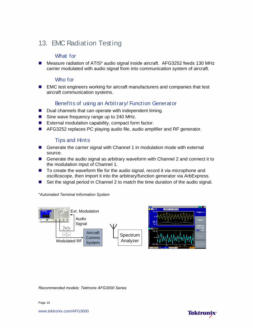
13. EMC Radiation Testing
What for Measure radiation of ATIS* audio signal inside aircraft. AFG3252 feeds 130 MHz
carrier modulated with audio signal from into communication system of aircraft.
Who for EMC test engineers working for aircraft manufacturers and companies that test
aircraft communication systems.
Benefits of using an Arbitrary/Function Generator Dual channels that can operate with independent timing. Sine wave frequency range up to 240 MHz. External modulation capability, compact form factor. AFG3252 replaces PC playing audio file, audio amplifier and RF generator.
Tips and Hints Generate the carrier signal with Channel 1 in modulation mode with external
source. Generate the audio signal as arbitrary waveform with Channel 2 and connect it to
the modulation input of Channel 1. To create the waveform file for the audio signal, record it via microphone and
oscilloscope, then import it into the arbitrary/function generator via ArbExpress. Set the signal period in Channel 2 to match the time duration of the audio signal.
*Automated Terminal Information System
AircraftCommsSystemModulated RF
AudioSignal
Ext. Modulation
SpectrumAnalyzerSpectrumAnalyzer
Recommended models: Tektronix AFG3000 Series

Page 17
www.tektronix.com/AFG3000
14. Characterizing I/Q Modulators
What for Measure IQ gain imbalance, quadrature error, frequency response, carrier feed
through, side-band suppression ratio and up-converter losses.
Who for Electronic design and test engineers working for semiconductor and wireless
communication equipment manufacturers.
Benefits of using an Arbitrary/Function Generator Dual channels that can easily be synchronized. Phase delay between channels adjustable on the fly, without interrupting the test. 240 MHz sine wave frequency range.
Tips and Hints Activate the synchronization mode of the dual channel signal generator by setting
Frequency CH1=CH2 to On and initiating Align Phase. Determine gain and phase errors by adjusting amplitude and phase of one
channel until undesired sideband power is minimized. The differences in amplitude and phase settings between channels 1 and 2 equal the gain imbalance and quadrature error.
Recommended models: Tektronix AFG3000 Series

Page 18
www.tektronix.com/AFG3000
Education-Related Applications 15. Measure Frequency Response of Bandpass Filter
What for Stimulate filter with swept sinewave and measure filter’s frequency response with
spectrum analyzer.
Who for Electronic design engineers working for filter vendors and wireless
communication equipment vendors. Professors and lab managers working in student labs in universities.
Benefits of using an Arbitrary/Function Generator Ease of use. Large screen shows all relevant waveform and sweep parameters at a single
glance for full confidence in correct settings. Compact form factor leaves more room on the bench for device and cables.
Tips and Hints If only an oscilloscope is available, and no spectrum analyzer, trigger on the
sweep start via the generator's trigger output, set the oscilloscope's time scale to match the generator's sweep time and interpret it as frequency values.
Bandpass Filter
Spectrum Analyzer
Recommended models: Tektronix AFG3000 Series
Page 19
www.tektronix.com/AFG3000
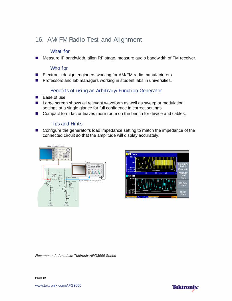
16. AM/FM Radio Test and Alignment
What for Measure IF bandwidth, align RF stage, measure audio bandwidth of FM receiver.
Who for Electronic design engineers working for AM/FM radio manufacturers. Professors and lab managers working in student labs in universities.
Benefits of using an Arbitrary/Function Generator Ease of use. Large screen shows all relevant waveform as well as sweep or modulation
settings at a single glance for full confidence in correct settings. Compact form factor leaves more room on the bench for device and cables.
Tips and Hints Configure the generator's load impedance setting to match the impedance of the
connected circuit so that the amplitude will display accurately.
Recommended models: Tektronix AFG3000 Series

Page 20
www.tektronix.com/AFG3000
Automotive Applications 17. Test & Optimization of Engine Control Units
What for Simulate various automotive sensor signals, such as pressure, temperature,
speed, rotation and angular position for functional test and optimization of engine control units (ECU) for automotive applications.
Who for Electronic design engineers working in automotive electronics
Benefits of using an Arbitrary/Function Generator Large display confirms all settings at a single glance. Amplitude can be entered as Vpp/Offset or as High/Low values. Powerful waveform creation and editing capability of ArbExpress. Amplitude up to 20 Vpp eliminates need for external amplifier.
Tips and Hints Activate the synchronization mode of the dual channel signal generator by setting
Frequency CH1=CH2 to On and initiating Align Phase. To synchronize the clocks multiple generators, use one generator as master and
connect its Sync Clock output to the Sync Clock inputs of the other generators. To synchronize multiple generators in phase, set them into Burst – Inf-Cycles
mode, and start them simultaneously via an external signal.
cam shaft
EngineIgnition
fuel injectiontiming control
ignitionanalog
DSP Platform(ECU Emulator)
Recommended models: Tektronix AFG3021B, AFG3022B, AFG3011

Page 21
www.tektronix.com/AFG3000
18. Simulation of Automotive Sensor Signals
What for Simulate crankshaft, camshaft, wheel, knock and other automotive engine sensor
signals.
Who for Electronic design engineers designing electronic engine control systems for
automobiles.
Benefit of using an Arbitrary/Function Generator Dual channels Powerful waveform creation and editing capability of ArbExpress. Ease of use and compact form factor of instrument.
Tips and Hints Activate the synchronization mode of the dual channel signal generator by setting
Frequency CH1=CH2 to On and initiating Align Phase. To create the waveform files, acquire the life signal with an oscilloscope, then
import it into the arbitrary/function generator via ArbExpress.
Power TrainControl Module
Camshaft Signal
Crankshaft Signal
Recommended models: Tektronix AFG3000 Series
Page 22
www.tektronix.com/AFG3000
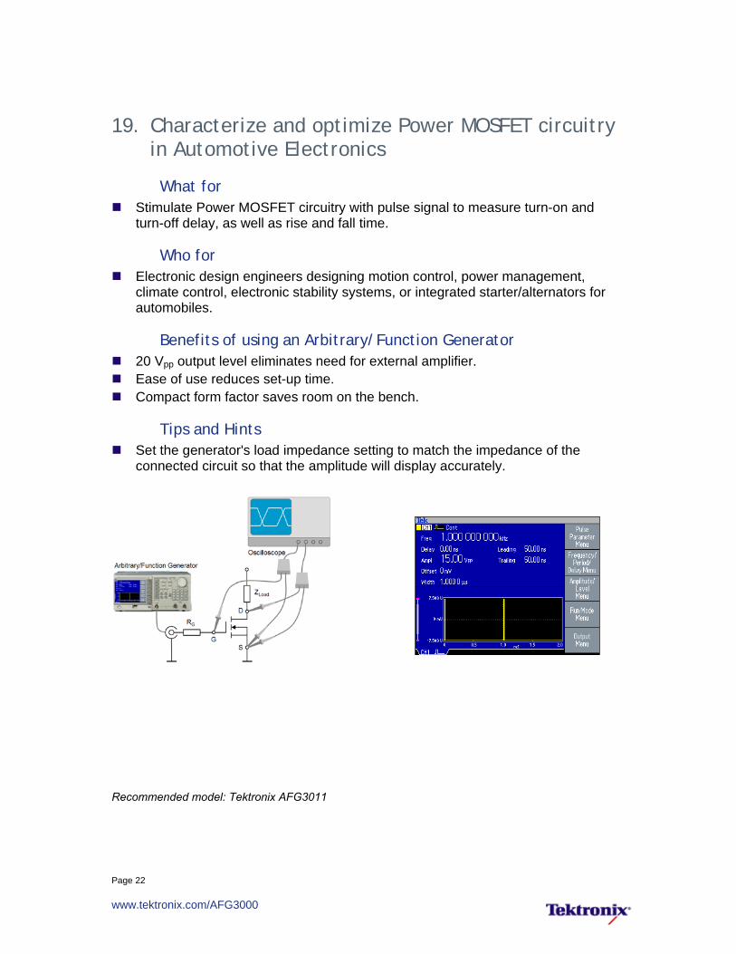
19. Characterize and optimize Power MOSFET circuitry in Automotive Electronics
What for Stimulate Power MOSFET circuitry with pulse signal to measure turn-on and
turn-off delay, as well as rise and fall time.
Who for Electronic design engineers designing motion control, power management,
climate control, electronic stability systems, or integrated starter/alternators for automobiles.
Benefits of using an Arbitrary/Function Generator 20 Vpp output level eliminates need for external amplifier. Ease of use reduces set-up time. Compact form factor saves room on the bench.
Tips and Hints Set the generator's load impedance setting to match the impedance of the
connected circuit so that the amplitude will display accurately.
Recommended model: Tektronix AFG3011

Page 23
www.tektronix.com/AFG3000
20. Analyzing Switching Waveforms of IGBT circuitry
What for Measure on and off switching characteristics of IGBT circuitry for ignition coil
drives, motor controllers, safety related systems in automobiles, and various industrial applications.
Who for Electronic design engineers working for: Automotive electronics vendors who design motion control, power management,
climate control, electronic stability systems, or integrated starter/alternators for automobiles.
Manufacturers of induction heating and welding equipments
Benefits of using an Arbitrary/Function Generator 20 Vpp output level eliminates need for external amplifier. Ease of use reduces set-up time. Compact form factor saves room on the bench.
Tips and Hints Set the generator's load impedance setting to match the impedance of the
connected circuit so that the amplitude will display accurately. Adjust the pulse repetition frequency, amplitude and edge transitions to observe
whether the design objectives with regard to switching energy, on-state losses, and staying within the safe operating area are met.
Recommended model: Tektronix AFG3011

Page 24
www.tektronix.com/AFG3000
Medical Applications
21. Testing Pacemakers, Cardioverter Defibrillators, and other Implantable Medical Devices
What for The AFG3022B simulates normal and irregular biomedical signals (e.g. heart
fibrillation) for the functional test of medical devices.
Who for Electronic design and test engineers designing medical devices.
Benefits of using an Arbitrary/Function Generator Tightly synchronized dual channels. Floating outputs to generate differential signals. Instrument’s ease of use and compact form factor.
Tips and Hints Acquire life signal with any Tektronix oscilloscope and convert to AFG waveform
via ArbExpress software. After setting up Channel 1 with desired waveform, frequency and amplitude,
duplicate inverse settings to Channel 2 via CH1 Complement function. Activate the synchronization mode of the dual channel signal generator by setting
Frequency CH1=CH2 to On and initiating Align Phase.
MedicalDevice
IsolationC
ircuit
µV Level
Recommended models: Tektronix AFG3000 Series

Page 25
www.tektronix.com/AFG3000
22. Testing Medical Ultrasound Equipment
What for Drive ultrasound transducer with sine wave bursts to test medical imaging
system.
Who for Electronic design engineers developing medical ultrasound equipment. Researchers working in universities engaged in ultrasound research.
Benefits of using an Arbitrary/Function Generator Ease of use. Compact form factor.
Tips and Hints Use the trigger output to trigger the measurement device or imaging system at
the beginning of every burst cycle.
Trigger
Ultrasound ImagingSystem
Ultrasound Transducer
Detector
PowerAmplifier
Recommended models: Tektronix AFG3011/AFG3102

Page 26
www.tektronix.com/AFG3000
23. Testing Detector Circuit of Medical Ultrasound Equipment
What for Simulate ultrasound detector signal to characterize input circuit of medical
ultrasound system.
Who for Electronic design engineers working for medical diagnostic equipment
manufacturers. Researchers working in universities engaged in ultrasound research.
Benefit of using an Arbitrary/Function Generator Ability to add noise and jitter internally. Ease of use. Compact form factor.
Tips and Hints Add noise internally by activating Noise Add function. Add jitter internally by operating the instrument in Phase Modulation mode.
Ultrasound Diagnostic
System
Arbitrarywaveform
Recommended models: Tektronix AFG3101/AFG3102

Page 27
www.tektronix.com/AFG3000
Industrial Applications 24. Characterizing Dynamic Performance of Hydraulic
Servo Valves
What for AFG stimulates servo valve with square wave to determine actuating time (step
response), frequency response (Bode plot) and other specifications for datasheet.
Who for Electromechanical design engineers involved in design and manufacture of
hydraulic servo valves.
Benefits of using an Arbitrary/Function Generator Ability to generate variety of waveshapes (square, ramp, sine, arb). >10 Vpp to determine valve characteristics in overdrive. Ease of use.
Tips and Hints Set the generator's load impedance setting to match the impedance of the
connected circuit so that the amplitude will display accurately. To drive a device with 0 or 4 to 20 mA input, calculate the corresponding voltage
settings for the generator based on the device's input impedance.
DynamicSignal
Analyzer
Process
HydraulicServo Valve
Recommended models: Tektronix AFG3000 Series

Page 28
www.tektronix.com/AFG3000
Research Applications 25. Driving and Modulating Laser Diodes
What for Drive laser diodes and electro-optical modulators for laser based communication
systems.
Who for Researchers working in universities and research institutes who are involved with
optical communication
Benefits of using an Arbitrary/Function Generator Dual channels that can operate with independent timing and operating modes. Arbitrary waveforms up to 125 MHz. Versatility, ease of use.
Tips and Hints Set the generator's load impedance setting to match the impedance of the
connected circuit so that the amplitude will display accurately.
PC with MatLab
Waveform
Electro Optical
Modulator
Electro Optical
ModulatorLaser Diode
AM PM
PhotoDiode
Recommended model: Tektronix AFG3252

Page 29
www.tektronix.com/AFG3000
Tektronix AFG3000 Series Arbitrary/Function Generators The Next Generation of Signal Generation
Model Channels Sample Rate
(Waveform Length) Memory Depth
Output Bandwidth
Amplitude (into 50 )
AFG3011 1 250 MS/s 128 K 10 MHz 20 mVp-p to 20 Vp-p
AFG3021B 1 250 MS/s 128 K 25 MHz 10 mVp-p to 10 Vp-p
AFG3022B 2 250 MS/s 128 K 25 MHz 10 mVp-p to 10 Vp-p
AFG3101 1 1 GS/s (≤ 16K)
250 MS/s (>16K) 128 K 100 MHz 20 mVp-p to 10 Vp-p
AFG3102 2 1 GS/s (≤ 16K)
250 MS/s (>16K) 128 K 100 MHz 20 mVp-p to 10 Vp-p
AFG3251 1 2 GS/s (≤ 16K)
250 MS/s (>16K) 128 K 240 MHz 50 mVp-p to 5 Vp-p
AFG3252 2 2 GS/s (≤ 16K)
250 MS/s (>16K) 128 K 240 MHz 50 mVp-p to 5 Vp-p
Large 5.6” display
Short-cut keys. Direct access to frequently used parameters and functions.
See your wave. Graphical representation of selected waveform and run mode give you full confidence in correct settings.
Settings are shown All relevant settings are shown on the screen, without a need to backtrack through layers of screen menus.
See the scale. Detailed time and amplitude scale.
Multi-channel choice. Display settings or waveforms of channels 1 and 2 side-by-side for a convenient comparison.
75W-23806-0