25_ koch _monitoring rot machine.pdf
TRANSCRIPT

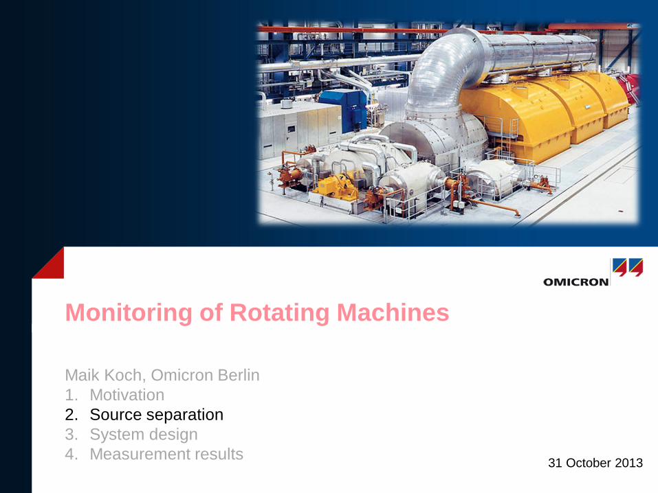
31 October 2013
Monitoring in Rotating Machines
Maik Koch, Omicron Berlin 1. Motivation 2. Source separation 3. System design 4. Measurement results
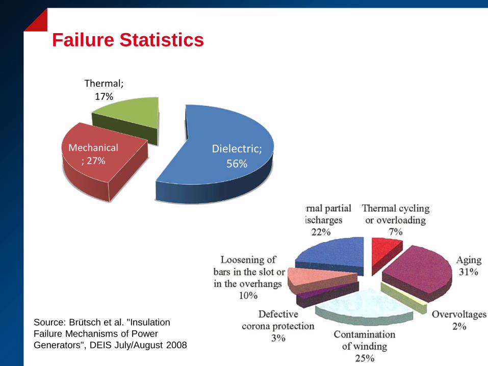
Failure Statistics
Source: Brütsch et al. "Insulation Failure Mechanisms of Power Generators", DEIS July/August 2008
Dielectric; 56%
Mechanical; 27%
Thermal; 17%
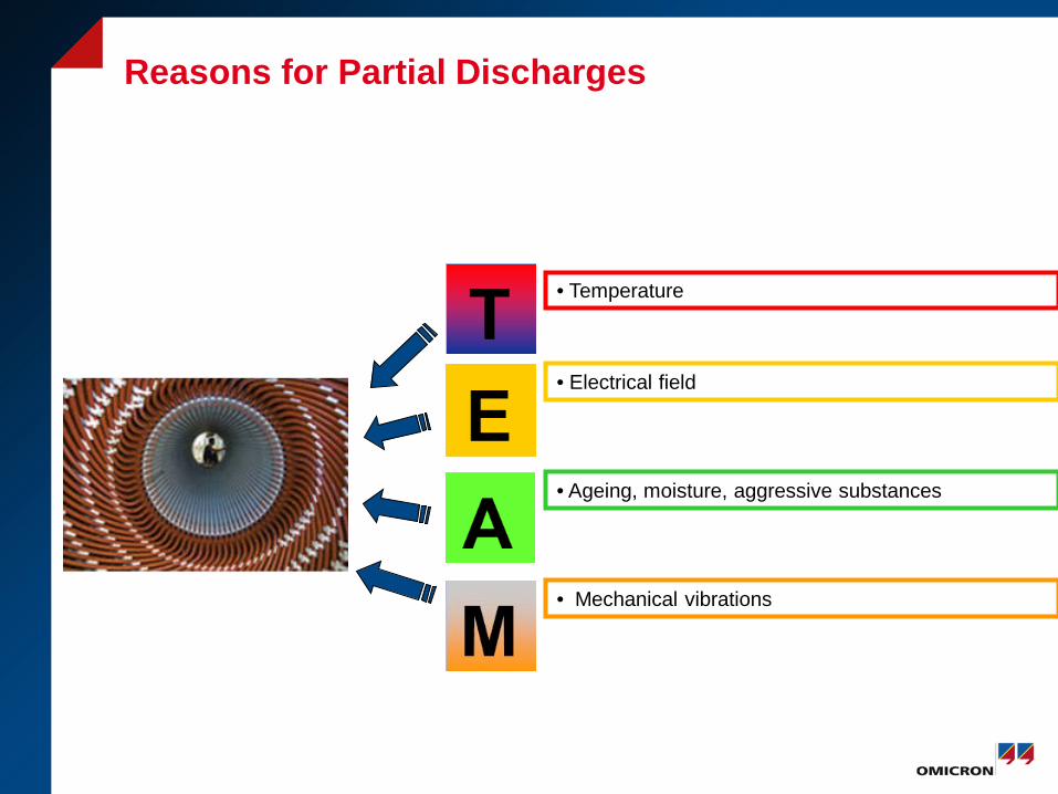
• Temperature
• Electrical field
• Ageing, moisture, aggressive substances
• Mechanical vibrations
Reasons for Partial Discharges
31 October 2013
Monitoring of Rotating Machines
Maik Koch, Omicron Berlin 1. Motivation 2. Source separation 3. System design 4. Measurement results

surface endwinding discharge - M
End winding surface - contamination - M
Slot discharge, semicon. paint abrasion - H
Insufficient Spacing, Sparking, Contact, Corona, - M
Micro voids - L
Delamination from conductor - H Delamination of
tape layers - H
S3
E1 & E2
PD Sources in Stator Insulation
E1 & E3
S1 & S2 & S4
A)Covering Tape B) Spacer, Coil-End Bracin C) Mica Tapes D) Grading/ Coating E) Semiconductive Coating F) Inner Semicon. coating G) Turn Insulation H) Slot Wedge / Seal I) Stator Core
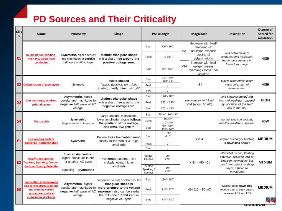
Class Name Symmetry Shape Phase angle Magnitude Description
Degree of hazard for insulation
S1 Delamination winding -
main Insulation from conductor
Asymmetric, higher density and magnitude in positive
half wave of AC voltage.
distinct triangular shape with a sharp rise around the
positive voltage zero.
Start 300°- 360° >S4
decrease with load/ temperature:
insulation expands closing of
delaminations
void between inner conductor and insulation,
better measurement in lower freq. range
HIGH Peak 0-60°
>S4
Increase with load wedge loosens,
overhangs loose, bar vibration
Stop 90°- 150°
S2 Delamination of tape layers Symetric sickle shaped
(shape depends on y-Axis scaling) mostly mixed with „G“
Start 120°- 210° 300°- 30°
>S4 bigger symmetrical inner
micro void, start of delamination
HIGH Peak /
Stop /
S3 Slot discharge, semicon paint abrasion
Asymmetric, higher density and magnitude in negative half wave of AC
voltage.
distinct triangular shape with a sharp rise around the
negative voltage zero.
Start 120°- 180° can increase with load >S4 (about 10 nC)
void between stator/ slot iron and insulation caused
by vibration of the bar/ coil in the slot
HIGH Peak 180° - 240°
Stop 270° - 330°
S4 Micro voids Symmetric , large amount of impulses
Large amount of impulses, lower amplitude, shape follows
the gradient of the voltage, also wave like pattern
Start 270°-0° 90°- 180°
normal small air pockets, healthy insulation system LOW Peak
30°-90° 210°- 270°
Stop 90° - 180°
270° - 360°
E1 End winding surface discharge - contamination Symmetric
Pattern looks like “rabbit ears”, mostly mixed with “S4”, high
amplitude
Start ~30° ~210°
>>S4
Surface discharge/ tracking in enwinding section
MEDIUM Peak /
Stop /
E2 Insufficient Spacing,
Tracking, Sparking, Contact, Corona, Floating Potential
Corona – Asymmetric: higher amplitude in one
or another AC cycle horizontal patterns, also
multiple levels, higher amplitude
“center” Corona
90° 270°
>>S4 (>50 nC)
all kind of corona, floating potential, sparking. can be between the winding but
also from contact or sharp edges, difficult to
distinguish
MEDIUM „center“
Sparking / contact
30° 210° Sparking - Symmetric
E3
Connection area between slot corona protection and
end winding corona protection, surface
endwinding discharge
Asymmetric, higher density and magnitude in negative half wave of AC
voltage.
compared to slot discharges the triangular shape is
more oriented to the voltage maximum also can be similar like “E1” one “rabbit ear” in
negative AC cycle
Start 120°- 180°
>S4 (10 – 50 nC) Discharge in enwinding
section due to bad contact between AGS and EGS
MEDIUM Peak 210° - 270°
Stop 270° - 330°
PD Sources and Their Criticality
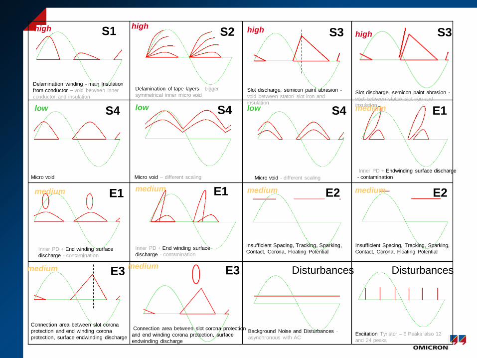
Excitation Tyristor – 6 Peaks also 12 and 24 peaks
Disturbances
Background Noise and Disturbances - asynchronous with AC
Disturbances
Delamination winding - main Insulation from conductor – void between inner conductor and insulation
S1 high
Slot discharge, semicon paint abrasion - void between stator/ slot iron and insulation
S3 high
Delamination of tape layers - bigger symmetrical inner micro void
S2 high
Connection area between slot corona protection and end winding corona protection, surface endwinding discharge
E3 medium
Inner PD + Endwinding surface discharge - contamination
E1 medium
Insufficient Spacing, Tracking, Sparking, Contact, Corona, Floating Potential
E2 medium
Inner PD + End winding surface discharge - contamination
E1 medium Micro void - different scaling
S4 low
Micro void – different scaling
S4 low
Micro void
S4 low
Insufficient Spacing, Tracking, Sparking, Contact, Corona, Floating Potential
E2
E3 medium
Connection area between slot corona protection and end winding corona protection, surface endwinding discharge
Slot discharge, semicon paint abrasion - void between stator/ slot iron and insulation
S3 high
Inner PD + End winding surface discharge - contamination
medium E1 medium

The Challenge: Source Separation
Background Noise and Disturbances - asynchronous with AC
Disturbances
200 pC
Inner PD + End winding surface discharge - contamination
E1 medium
900 pC
Delamination of tape layers - bigger symmetrical inner micro void
S2 high
500 pC
1,4 nC
Q
time
Alarm

CORE
L1 L2
L3 neutral
3 2 1 36 35 34 33 32 31 30 29 28 27 26 25 24 23 22 21 20 19 18 17 16 15 14 13 12 11 10 9 8 7 6 5 4 3 2 1 36 35 34 33 32
E E
H
TE
Coupling between Phases
> 2013-10-31
10/31/2013 Page: 10 © OMICRON
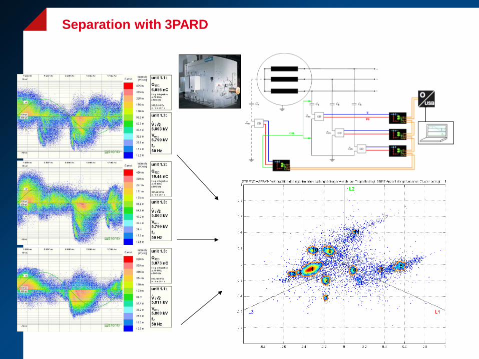
Separation with 3PARD

> 2013-10-31
cluster 4
cluster 9
cluster 6
3PARD
10/31/2013 Page: 11 © OMICRON
Back Transformermation to PRPD

Supervised Learning
Feature Selection
Classification
Classification
Class (PD source/no PD source)
Classifier Training
Learning informa-
tion
Feature Extraction
Feature Selection
PRPD Reference Database
Probability based
Decision Tree Generation
Decision making
Rule bases
Feature Choice
Feature Extraction
Feature Extraction
Categorization of feature values
Tree Adjustment
CART Framework
Feature Choice
Feature Extraction
Categorization of feature values
Tree Descent Decision Rules
Combination of classification results - PD expert‘s work
PRPD Data Collection
Manual Feature
Definition
Page 12 © OMICRON
Pattern Recognition

Page 13 © OMICRON
PRPD Pattern Classification Report (example)
31 October 2013
Monitoring of Rotating Machines
Maik Koch, Omicron Berlin 1. Motivation 2. Source separation 3. System design 4. Measurement results

PDM 600-3 Module
Monitoring Server
Controller MCU 502 with Relais
19‘‘FO Patchpanel
FO < 1000 m
Triaxial cable < 20m
Coupling capacitor MCC 124 / 112
Monitoring System OMS600

Page: 16 10/31/2013
Coupling Capacitors MCC 124 / MCC112

> 10/31/2013
System Configuration Multiple Generators

Temporary Monitoring
> One case for easy transport > “Plug and Play” (pre-wired) > IP65 (NEMA 4)
Fixed monitoring vs. Portable monitoring OMS 600 OMS 605

Browser based Monitoring Software All measurement systems System per Asset
Configuration User-Settings

Live Trend
20

Historical Data
21
31 October 2013
Monitoring of Rotating Machines
Maik Koch, Omicron Berlin 1. Motivation 2. Source separation 3. System design 4. Measurement results
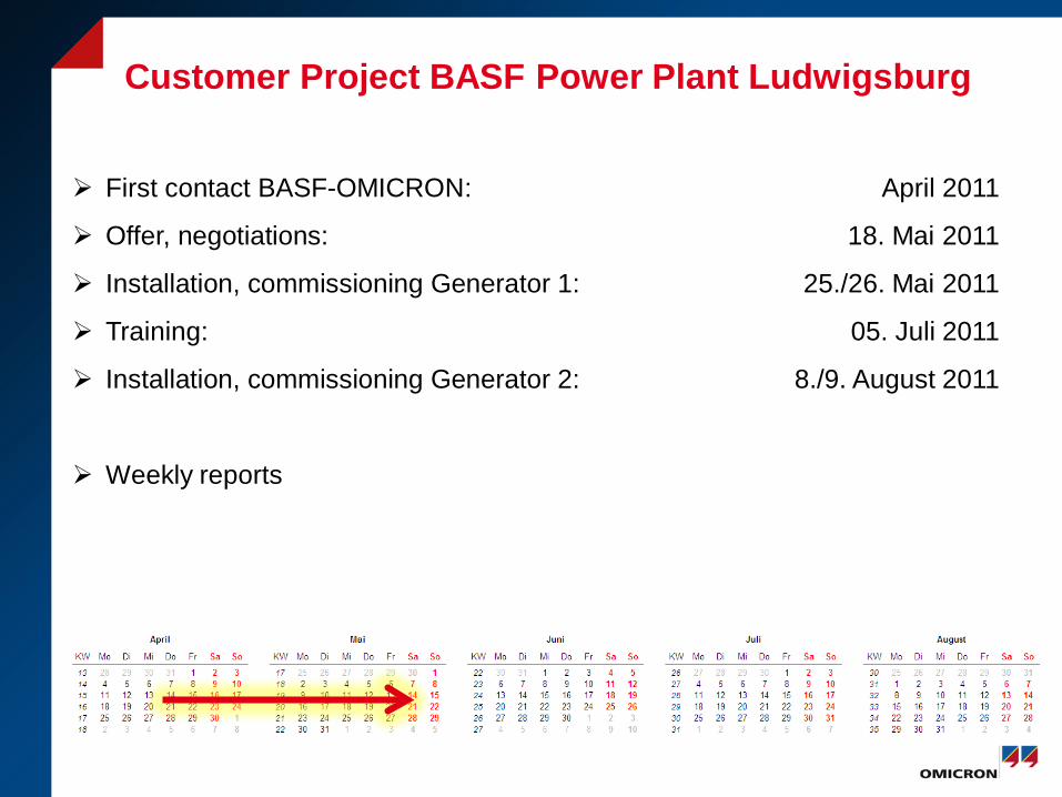
Customer Project BASF Power Plant Ludwigsburg
First contact BASF-OMICRON: April 2011
Offer, negotiations: 18. Mai 2011
Installation, commissioning Generator 1: 25./26. Mai 2011
Training: 05. Juli 2011
Installation, commissioning Generator 2: 8./9. August 2011
Weekly reports
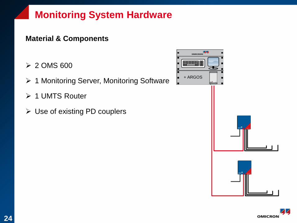
+ ARGOS
Monitoring System Hardware
24
Material & Components
2 OMS 600
1 Monitoring Server, Monitoring Software
1 UMTS Router
Use of existing PD couplers
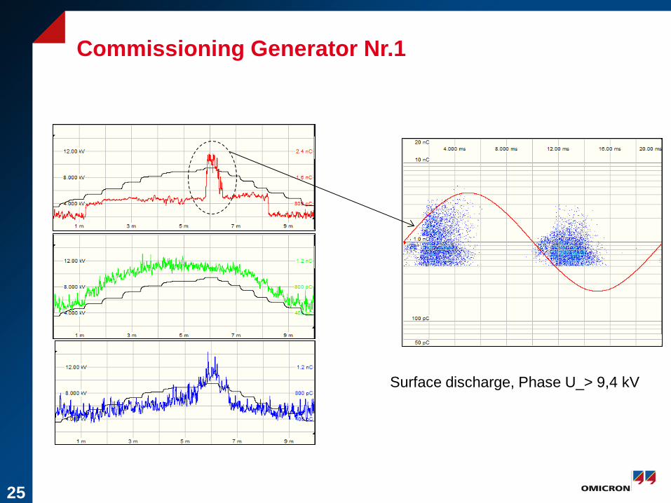
Commissioning Generator Nr.1
Surface discharge, Phase U_> 9,4 kV
25

Monitoring Generator Nr.1
Surface Discharge Phase U
Phase U − Phase V − Phase W −
26
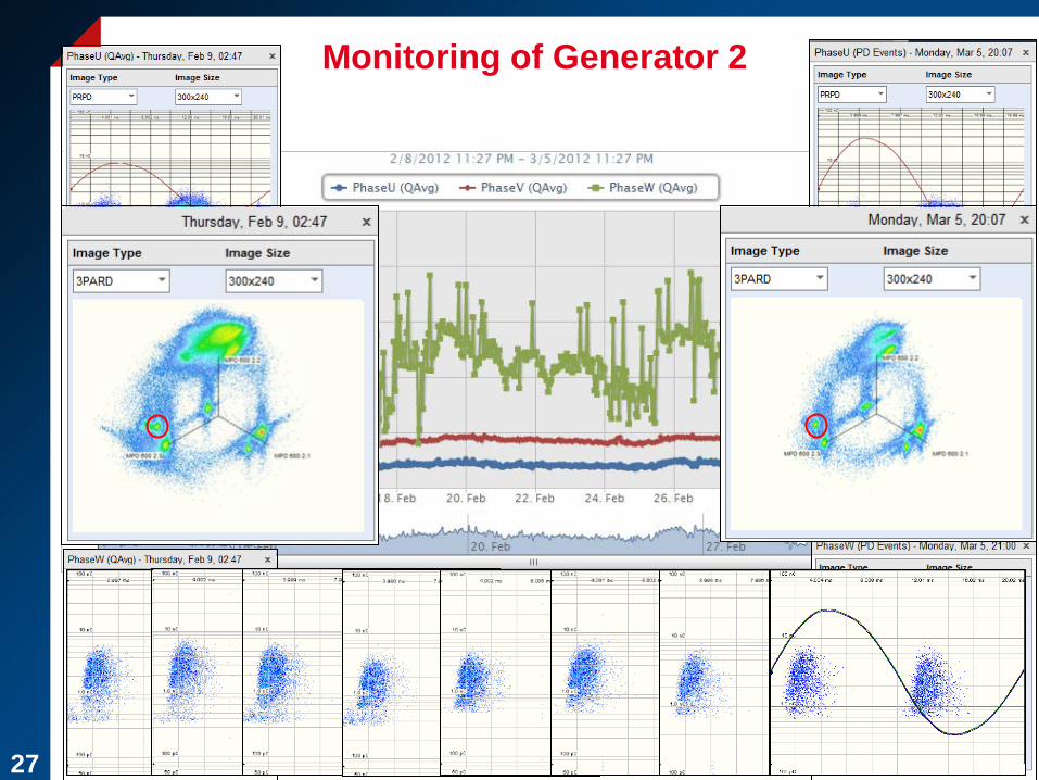
Monitoring of Generator 2
27
28
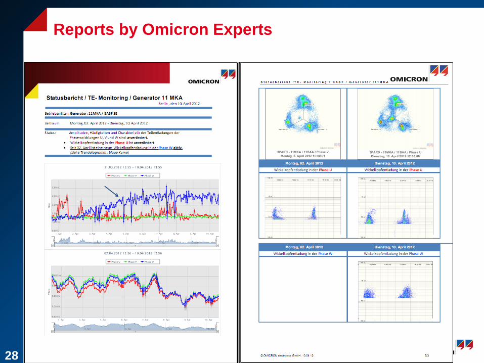
Reports by Omicron Experts

Summary
On-line monitoring provides results under real operating conditions
Source separation
System design
Diagnosis SW
Monitoring SW
Until now about 50 Installations