2565-799 rev b...tire size 8-14.5 lt 14 ply 8-14.5 lt 14 ply 8-14.5 lt 14 ply 8-14.5 lt 14 ply...
TRANSCRIPT
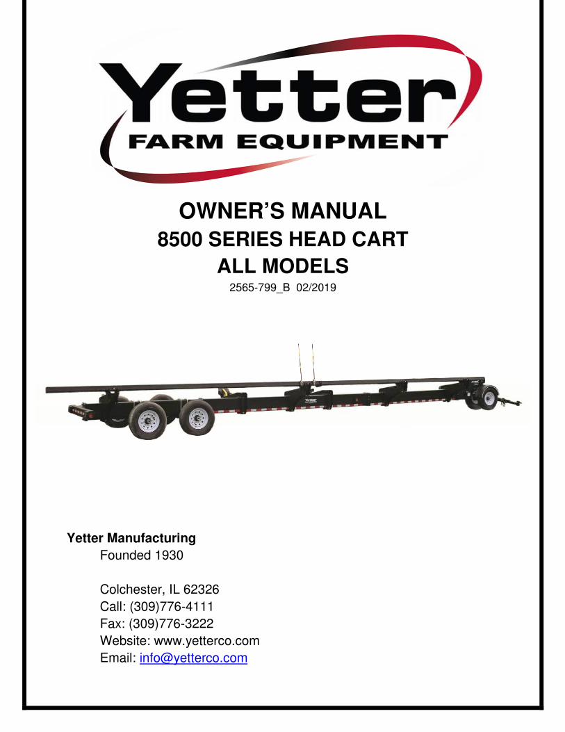
OWNER’S MANUAL
8500 SERIES HEAD CART
ALL MODELS 2565-799_B 02/2019
Yetter Manufacturing
Founded 1930
Colchester, IL 62326
Call: (309)776-4111
Fax: (309)776-3222
Website: www.yetterco.com
Email: [email protected]
2
FOREWORD
You’ve just joined an exclusive but rapidly
growing club. For our part, we want to
welcome you to the group and thank you for
buying a Yetter product.
We hope your new Yetter products will help
you achieve two goals: increase your
productivity and increase your efficiency so
that you may generate more profit.
This SAFETY ALERT SYMBOL
indicates important safety
messages in the manual. When
you see this symbol, be alert to the
possibility of PERSONAL INJURY and
carefully read the message that follows.
The word NOTE is used to convey
information that is out of context with the
manual text. It contains special information
such as specifications, techniques and
reference information of a supplementary
nature.
The word IMPORTANT is used in the text
when immediate danger will occur to the
machine due to improper technique or
operation.
It is the responsibility of the user to read the
owner’s manual, comply with safe and
correct operating procedure, and to
lubricate and maintain the product
according to the information listed in the
owner’s manual.
The user is responsible for inspecting their
machine and for having parts repaired or
replaced when it is damaged or worn.
Continued use of a damaged or worn part
can cause injury or more extensive damage
to the machine.
If you have any questions regarding the
information given in this manual, consult
your local Yetter dealer or contact:
Yetter Manufacturing Co.
(309)776-4111
(800)447-5777
Website: www.yetterco.com
Email: [email protected]
WARRANTY
Yetter Manufacturing warrants all products manufactured and sold by it against defects
in material. This warry being expressly limited to replacement at the factory of such parts
or products that appear to be defective after inspection. The warranty does not obligate
Yetter Manufacturing to bear the cost of labor in replacement of parts. It is the policy of
the Company to make improvements without incurring obligations to add them to any
unit sold prior. No warranty is made, or authorized to be made, other than herein set
forth. This warranty is in effect for one year after purchase.
Dealer:__________________________
Yetter Manufacturing warrants its own products and cannot be held responsible
for damages to equipment on which they are mounted.
3
TABLE OF CONTENTS
SAFETY .................................................................................................. 4-5
GENERAL INFORMATION ..................................................................... 6-8
BOLT TORQUE .......................................................................................... 9
SET-UP ............................................................................................... 10-11
OPERATION ....................................................................................... 12-13
MAINTENANCE ....................................................................................... 14
PART IDENTIFICATION ..................................................................... 15-34

4
SAFETY INFORMATION
BE ALERT!
YOUR SAFETY IS INVOLVED
It is the responsibility of the owner, operator, or supervisor to know and instruct
everyone using this machine at the time of initial assignment and at least annually
thereafter, of the proper operation, precautions, and work hazard which exist in the
operation of the machine in accordance with OSHA regulations.
SAFETY IS NO ACCIDENT The following safety instructions combines with common sense will save your
equipment from needless damage and the operator from unnecessary exposure
to personal hazard. Pay special attention to the caution notes in the text. Review
this manual each year and with new and experience operators.
1. Read and understand the operator’s manual before operating this machine.
Failure to do so is considered a misuse of the equipment.
2. Make sure equipment is secure before use.
3. Always keep children away from equipment while in operation.
4. Make sure everyone that is not directly involved with the operation is clear of the
work area before use.
5. Be sure all safety devices, shield, and guards are in place and functional before
beginning operation
6. Shut off all power to the unit prior to adjustment, servicing, or cleaning.
7. Keep hands, feet, and clothing away from moving parts. It is a good idea to
remove all jewelry before starting the operation.
8. Visually inspect the machine periodically during operation for signs of excessive
vibration, loose fasteners, and unusual noises.

5
SAFETY INFORMATION
During Operation
• Regulate speed to field conditions. Maintain complete control at all times.
• Never lubricate equipment when in operation.
• Use extreme care when operating close to ditches, fences, or on hillsides.
• Do no leave towing vehicle unattended with engine running.
• Do no adjust the transporter with the head positioned over the unit.
Before Operation
• Secure the transport chains to towing vehicle before transporting. DO NOT
transport without the chains.
• Check for proper function of all available transport lights. Make sure that all
reflectors are clean and in place on the machine.
• This implement may not be equipped with brakes. Ensure that the towing vehicle
has adequate weight and braking capacity to tow this unit.
• Before transporting, secure the head with straps. Replace damaged or worn
straps, and avoid putting straps over rough or sharp surfaces. Use appropriate
number and capacity rating.
During Transport
• Comply with state and local laws governing highway safety when moving
machinery.
• Use transport lights as required by local laws to adequately warn operators of
other vehicles.
• Use good judgement when transporting equipment on highways. Regulate speed
to road conditions and maintain complete control.
• Slow down before making sharp turns to avoid tipping. Drive slowly over rough
ground and side slops.
• It is probable that this implement is taller, wider, and longer than the towing
vehicle. Become aware of and avoid all obstacles and hazards in the travel path
of the equipment such as power lines, ditches, etc.

6
GENERAL INFORMATION
8500 Series Head Cart Trailers
Model No. Description Est. Wt.
8500-027 27’ Head Cart 3260 lbs 8500-032 32’ Head Cart 4103 lbs 8500-038 38’ Head Cart 4358 lbs 8500-043 43’ Head Cart 4741 lbs 8500-048 48’ Head Cart 4970 lbs
Optional Equipment Model No. Description Est. Wt. 8500-001 Marker Pole 3 lbs
8500-144 Ball Hitch 2-5/16” 10 lbs 8500-166 Drop Pin Hitch 14 lbs
Service Kits Model No. Description Est. Wt. 8500-120 Rear Bearing and Drum Replacement Kit (1 Per Wheel) 40 lbs 8500-121 Lugnut and Stud Replacement Kit (1 Per Wheel) 4 lbs
8500-122 Front and Rear Bearing Replacement Kit (1 Per Wheel) 7 lbs 8500-123 Brake Replacement Kit (1 Per Axle) 10 lbs 8500-124 Front Bearing and Hub Replacement Kit (1 Per Wheel) 26 lbs

7
GENERAL INFORMATION
8500 Series Head Cart Trailers
• Central beam design with adjustable truss supports
• Spare cutter bar storage
• Dual 12” rest brackets to fit any header platform with tool-
less adjustments
• Drum brakes on rear axle(s)
• Front and rear torsion axles providing a smooth ride
• Molded front fenders protecting head and truck from road
debris
• Tongue rotates around to main beam for easy winter storage
and shipment
• 24” of telescoping hitch adjustment
• Dual safety chains with standard clevis hitch. Options for
drop-pin and ball hitch attachments
• LED lights and seven pin bladed receptacle for standard
towing vehicles
• Full length DOT reflective tape
• Tool box – 17 ¾” x 8” x 7”
• Full width rear light support brackets
• Durable black powder coat finish
• Made in the USA, manufactured and shipped from Macomb,
IL
8
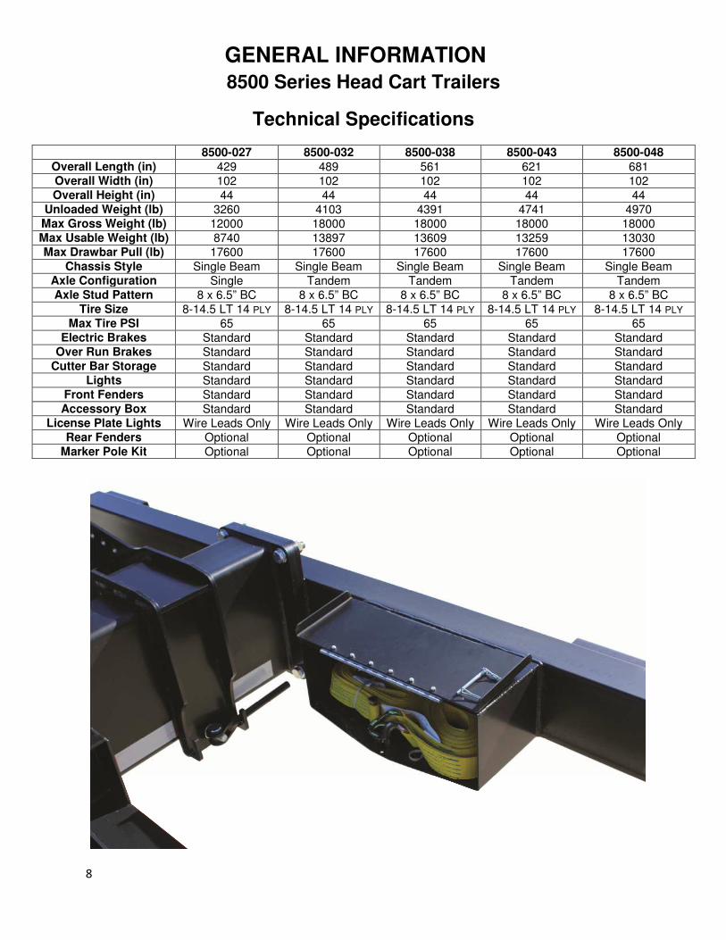
GENERAL INFORMATION
8500 Series Head Cart Trailers
Technical Specifications
8500-027 8500-032 8500-038 8500-043 8500-048
Overall Length (in) 429 489 561 621 681 Overall Width (in) 102 102 102 102 102 Overall Height (in) 44 44 44 44 44
Unloaded Weight (lb) 3260 4103 4391 4741 4970 Max Gross Weight (lb) 12000 18000 18000 18000 18000 Max Usable Weight (lb) 8740 13897 13609 13259 13030 Max Drawbar Pull (lb) 17600 17600 17600 17600 17600
Chassis Style Single Beam Single Beam Single Beam Single Beam Single Beam Axle Configuration Single Tandem Tandem Tandem Tandem Axle Stud Pattern 8 x 6.5” BC 8 x 6.5” BC 8 x 6.5” BC 8 x 6.5” BC 8 x 6.5” BC
Tire Size 8-14.5 LT 14 PLY 8-14.5 LT 14 PLY 8-14.5 LT 14 PLY 8-14.5 LT 14 PLY 8-14.5 LT 14 PLY Max Tire PSI 65 65 65 65 65
Electric Brakes Standard Standard Standard Standard Standard Over Run Brakes Standard Standard Standard Standard Standard
Cutter Bar Storage Standard Standard Standard Standard Standard Lights Standard Standard Standard Standard Standard
Front Fenders Standard Standard Standard Standard Standard Accessory Box Standard Standard Standard Standard Standard
License Plate Lights Wire Leads Only Wire Leads Only Wire Leads Only Wire Leads Only Wire Leads Only Rear Fenders Optional Optional Optional Optional Optional
Marker Pole Kit Optional Optional Optional Optional Optional

9
BOLT TORQUE
Important: Over tightening hardware can cause as much damage as under tightening.
Tightening hardware beyond the recommended range can reduce it shock load
capacity.
All hardware used on the 8500 Series Head Cart is Grade 5 unless otherwise specified.
If hardware must be replaced, be sure to replace it with hardware of equal size,
strength, and thread type.
The chart below is a guide for proper torque. Use it unless a specified torque
value is given elsewhere in the manual.
Torque is the force you apply to the wrench handle times the length of the handle.
Use a torque wrench wherever possible
The following table shows torque in ft-lbs for coarse thread hardware.

10
SET UP INSTRUCTIONS
Tires and Wheels 1. Using a safe lifting device and jack stands rated at a minimum of 2500 lbs, raise
the frame at least 16 ½” high
2. Install wheels and tires onto the axles and secure with provided lug nuts. Refer to
the table below for torque sequence and value.
• Start all lug nuts by hand to prevent cross threading
• Tighten nuts in the sequence shown below
• Lug nuts should be torqued before first road use and after each wheel
removal. Check and re-torque after the first 50 miles. A periodic check
during regular service is recommended.
Wheel Size Stud Size 1st Stage 2nd Stage 3rd Stage 14.5 X 7 9/16” 25 lb-ft 70 lb-ft 130 lb-ft
1
2
3
4 5
6
7 8
6.5” BC

11
SET UP INSTRUCTIONS
Test Lights Make sure no wires are pinched or cut during installation.
Keep all wires concealed to prevent them from getting caught on obstructions.
Attach 8500 Head Cart and wiring harness to tow vehicle to test the lights.
Check the following:
• Tail lights
• Brake lights
• Left and right turn signals with and without brakes applied
Note: If any of the light tests fail, check wiring harness on tow vehicle for proper
wiring.
ATTACH TO
TOW VEHICLE

12
OPERATION
Hitching 1. Position towing vehicle in front of header transport. Lift tongue latch handle and
extended inner tongue extension enough to attach to vehicle drawbar using a ¾”
minimum diameter hitch pin and lock in place. Back-up towing vehicle to re-latch
tongue.
2. Cross transport chains and connect to towing vehicle.
Note: Before hitching the header transport to any vehicle drawbar, be sure the pin
hole is located close enough to the rear of the vehicle drawbar to allow the
header transport tongue clevis to swing 90 degrees right or left of the centerline
without interference.
Note: When hitching, be sure not to pinch wire harness. Position the wire harness
away from all pinch points and any areas that may wear the harness.
CAUTION: BE SURE TRANSPORT TONGUE IS LATCHED
BEFORE TRANSPORTING, OTHERWISE JARRING COULD
OCCUR WHEN STOPPING UNIT, CAUSING A SUDDEN SHIFT OF
LOAD.
CAUTION: ALWAYS USE TRANSPORT CHAINS WHEN
TRANSPORTING IMPLEMENTS. FAILURE TO USE TRANSPORT
CHAIN COULD CAUSE PERSONAL INJURY OR DAMAGE IF
IMPLEMENT BECOMES DISENGAGED.
13
OPERATION
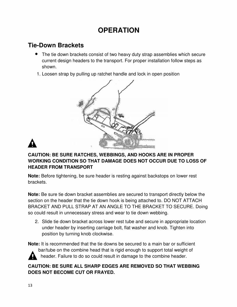
Tie-Down Brackets
• The tie down brackets consist of two heavy duty strap assemblies which secure
current design headers to the transport. For proper installation follow steps as
shown.
1. Loosen strap by pulling up ratchet handle and lock in open position
CAUTION: BE SURE RATCHES, WEBBINGS, AND HOOKS ARE IN PROPER
WORKING CONDITION SO THAT DAMAGE DOES NOT OCCUR DUE TO LOSS OF
HEADER FROM TRANSPORT
Note: Before tightening, be sure header is resting against backstops on lower rest
brackets.
Note: Be sure tie down bracket assemblies are secured to transport directly below the
section on the header that the tie down hook is being attached to. DO NOT ATTACH
BRACKET AND PULL STRAP AT AN ANGLE TO THE BRACKET TO SECURE. Doing
so could result in unnecessary stress and wear to tie down webbing.
2. Slide tie down bracket across lower rest tube and secure in appropriate location
under header by inserting carriage bolt, flat washer and knob. Tighten into
position by turning knob clockwise.
Note: It is recommended that the tie downs be secured to a main bar or sufficient
bar/tube on the combine head that is rigid enough to support total weight of
header. Failure to do so could result in damage to the combine header.
CAUTION: BE SURE ALL SHARP EDGES ARE REMOVED SO THAT WEBBING
DOES NOT BECOME CUT OR FRAYED.

14
MAINTENANCE
Bearings • Every 12,000 miles or once a year, repack wheel bearings with grease
o Inspect bearings for signs of wear such as discoloration of rollers,
spalling, pits, or metal flakes. Rollers and race should look shiny and new
if in good condition. If any of these signs are found, replace bearings
immediately.
Brakes • Every 12,000 miles or once a year, inspect brake shoes for wear. Be sure to
replace brake shoes before friction material wears away entirely. Failure to do so
can cause damage to the brake drum.
Service Kits For a visual part breakdown, go to the page listed.
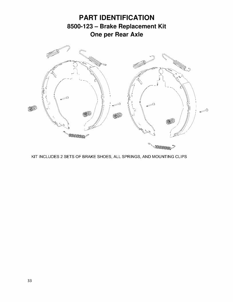
Model No. Description Page 8500-120 Rear Bearing and Drum Replacement Kit (1 Per Wheel) 37 8500-121 Lugnut and Stud Replacement Kit (1 Per Wheel) 38 8500-122 Front and Rear Bearing Replacement Kit (1 Per Wheel) 39 8500-123 Brake Replacement Kit (1 Per Axle) 40 8500-124 Front Bearing and Hub Replacement Kit (1 Per Wheel) 41

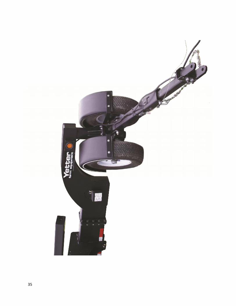
15
PART IDENTIFICATION
ITEM PART# DESCRIPTION 27' 32' 38' 43' 48'
1 2000-157 75-8 HUB ASSEMBLY 1 1 1 1 1
2 2502-244 3/8-16 X 1-1/4 HHCS GR 5 ZP 8 8 8 8 8
7 2502-425 3/4-10 X 5 HHFS GR8 ZP 1 1 1 1 1
10 2513-509 5/16-18X3/4TYP 23HHSTWHS ZP 1 1 1 1 1
11 2515-556 CABLE TIE, .35 X 36", BLACK (21598) 4 4 4 4 4
12 2520-255 3/8-16 LOCK HEX NUT, GR A ZP 8 8 8 8 8
15 2520-370 WHEEL NUT #N913557 8 8 8 8 8
16 2520-516 3/4-10NYLON INSERT LCKNT, GR 2, ZP 1 1 1 1 1
18 2520-563 1-8 NYLON LOCK NUT GR C, ZP 1 1 1 1 1
19 2520-600 3/8-24 LOCK HEX NUT, GR C, ZP 6 6 6 6 6
20 2526-251 3/8 STANDARD FLATWASHER ZP 16 16 16 16 16
22 2526-542 1" SAE FLAT WASHER ZP 2 2 2 2 2
23 2565-366 AVENGER COULTER DECAL 1 1 1 1 1
24 2565-466 SERIAL NUMBER DECAL 1 1 1 1 1
25 2565-822 YETTER DECAL 5 5 5 5 5
26 - SIZE DECAL, XX' 1; 2565-828 1; 2565-827 1; 2565-826 1; 2565-825 1; 2565-823
27 2565-829 MADE IN U.S.A. DECAL 1 1 1 1 1
28 2565-830 TORQUE CHECK DECAL 1 1 1 1 1
29 2565-831 HARNESS CONNECTION DECAL 1 1 1 1 1
32 2940-577 11.5" BLACK CABLE TIE NYLON 40LB, INDIVIDUAL 10 18 18 18 18
33 8500-100 EXTENDABLE TONGUE ASSEMBLY 1 1 1 1 1
37 8500-200 GOOSENECK W.A. 1 1 1 1 1
38 8500-203 6500LB AXLE W.A. 1 1 1 1 1
46 8500-226 FENDER MOUNT BRACKET W.A. 2 2 2 2 2
49 8500-335 BUSHING 2 2 2 2 2
50 8500-337-D FENDER 2 2 2 2 2
52 8500-370 AMBER MARKER LIGH 4 4 4 4 4
62 8500-384 CLAMP PLATE, INNER FENDER 4 4 4 4 4
65 8500-387 2.5 IN GROMMET 6 6 6 6 6
70 8500-411 TIRE AND WHEEL ASSEMBLY; 8-14.5 14 PLY LOAD G 4 6 6 6 6
71 8500-416 .5 ID, .25 MATERIAL THICKNESS, .813 PILOT GROMMET 1 1 1 1 1
72 2502-766 1-8 X 7-1/2 HHCS GR 8 ZP 1 1 1 1 1
use 8500-048 front end image for balloons
QUANTITY; P/N

16
PART IDENTIFICATION

17
PART IDENTIFICATION
ITEM PART# DESCRIPTION 27' 32' 38' 43' 48'
39 8500-207 MAIN TUBE FRONT SECTION W.A - 1 1 1 1
40 8500-208 MAIN 22FT SECTION W.A. 1 - - - 1
41 8500-209 TAIL END W.A. - - 1 1 1
43 8500-218 MAIN 17FT SECTION W.A. - 1 - 1 -
44 8500-220 MAIN 12FT SECTION W.A. - - 1 - -
55 8500-373 V92 DOT TAPE 2"X6" RED/6" WHT 12' - 2 2 2 2
56 8500-374 V92 DOT TAPE 2"X6" RED/6" WHT 21.5' 2 - - - 2
57 8500-375 V92 DOT TAPE 2"X6" RED/6" WHT 8.5' - - 2 2 2
64 8500-391 V92 DOT TAPE 2"X6" RED/6" WHT 16.5' - 2 - 2 -
66 8500-396 V92 DOT TAPE 2"X6" RED/6" WHT 11.5' - - 2 - -
QUANTITY
18
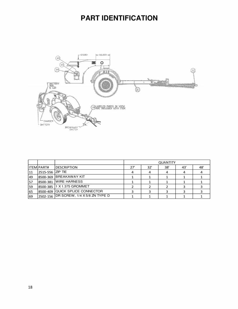
PART IDENTIFICATION
ITEM PART# DESCRIPTION 27' 32' 38' 43' 48'
11 2515-556 ZIP TIE 4 4 4 4 4
49 8500-369 BREAKAWAY KIT 1 1 1 1 1
57 8500-381 WIRE HARNESS 1 1 1 1 1
59 8500-385 1 X 1.375 GROMMET 2 2 2 3 3
65 8500-409 QUICK SPLICE CONNECTOR 3 3 3 3 3
69 2502-156 DR SCREW, 1/4 X 5/8 ZN TYPE D 1 1 1 1 1
QUANTITY
19
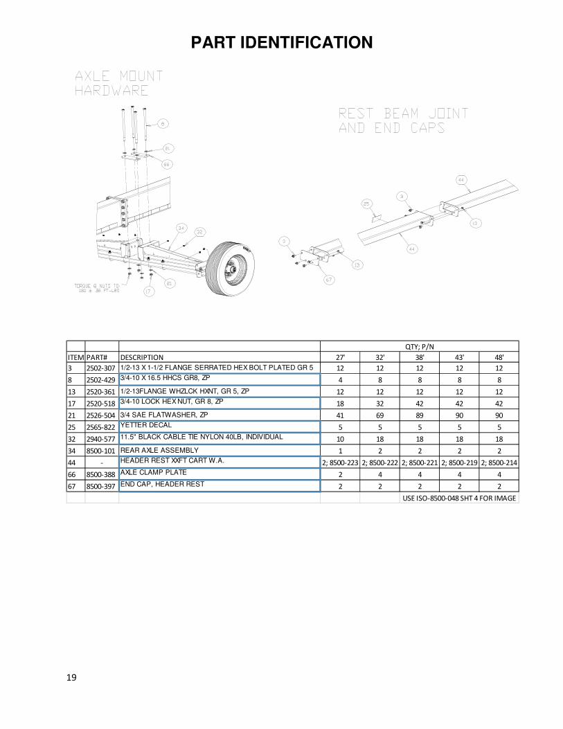
PART IDENTIFICATION
ITEM PART# DESCRIPTION 27' 32' 38' 43' 48'
3 2502-307 1/2-13 X 1-1/2 FLANGE SERRATED HEX BOLT PLATED GR 5 12 12 12 12 12
8 2502-429 3/4-10 X 16.5 HHCS GR8, ZP 4 8 8 8 8
13 2520-361 1/2-13FLANGE WHZLCK HXNT, GR 5, ZP 12 12 12 12 12
17 2520-518 3/4-10 LOCK HEX NUT, GR 8, ZP 18 32 42 42 42
21 2526-504 3/4 SAE FLATWASHER, ZP 41 69 89 90 90
25 2565-822 YETTER DECAL 5 5 5 5 5
32 2940-577 11.5" BLACK CABLE TIE NYLON 40LB, INDIVIDUAL 10 18 18 18 18
34 8500-101 REAR AXLE ASSEMBLY 1 2 2 2 2
44 - HEADER REST XXFT CART W.A. 2; 8500-223 2; 8500-222 2; 8500-221 2; 8500-219 2; 8500-214
66 8500-388 AXLE CLAMP PLATE 2 4 4 4 4
67 8500-397 END CAP, HEADER REST 2 2 2 2 2
QTY; P/N
USE ISO-8500-048 SHT 4 FOR IMAGE

20
PART IDENTIFICATION
ITEM PART# DESCRIPTION 27' 32' 38' 43' 48'
5 2502-350 1/2-13 X 2 HHCS, GR 8, ZP 3 3 3 4 4
6 2502-369 1/2-13 X 8 HHCS GR. 5 ZP 2 2 2 2 2
10 2502-431 3/4-10 X 9 HHCS GR8, ZP 5 5 5 6 6
16 2520-363 1/2-13 NYL INSERT LOCKNUT, GR 2 2 2 2 2 2
23 2526-504 3/4 SAE FLATWASHER, ZP 41 69 89 90 90
32 2570-452 COTTER PIN, 1/4 X 4 STEEL ZP 10 10 10 12 12
33 2570-454 KLIK PIN DANUSER #7524 8 8 8 8 8
44 8500-212 UPPER SUPPORT W.A. 3 3 3 4 4
45 8500-213 UPPER HEADER SUPPORT W.A. 3 3 3 4 4
47 8500-217 ADJUSTMENT HANDLE 5 5 5 6 6
49 8500-227 LOWER SUPPORT W.A. 2 2 2 2 2
50 8500-228 LOWER HEADER REST W.A. 2 2 2 2 2
60 8500-376 2" RATCHET 2 2 2 2 2
61 8500-377 3/4 DIAMETER PULL PIN 10 10 10 12 12
62 8500-378 THREADED PIN 5 5 5 6 6
70 8500-406 SIDE PLATE 4 4 4 4 4
QTY; P/N
USE ISO-8500-048 SHT 5 FOR IMAGE

21
PART IDENTIFICATION
ITEM PART# DESCRIPTION 27' 32' 38' 43' 48'
6 2502-409 3/4-10 X 3 HHCS GR 5 ZP 14 24 34 34 34
17 2520-518 3/4-10 LOCK HEX NUT, GR 8, ZP 18 32 42 42 42
21 2526-504 3/4 SAE FLATWASHER, ZP 41 69 89 90 90
QTY; P/N
USE ISO-8500-048 SHT 6 FOR IMAGE

22
PART IDENTIFICATION
ITEM PART# DESCRIPTION 27' 32' 38' 43' 48'
6 2502-409 3/4-10 X 3 HHCS GR 5 ZP 14 24 34 34 34
17 2520-518 3/4-10 LOCK HEX NUT, GR 8, ZP 18 32 42 42 42
21 2526-504 3/4 SAE FLATWASHER, ZP 41 69 89 90 90
25 2565-822 YETTER DECAL 5 5 5 5 5
35 8500-102 TAIL LIGHTS ASSEMBLY 1 1 1 1 1
36 8500-109 BOLT BAG 1 1 1 1 1
53 8500-371 LED TAIL LIGHT 2 2 2 2 2
54 8500-372 RED MARKER LIGHT 2 2 2 2 2
63 8500-385 1 X 1.375 GROMMET 2 2 2 3 3
64 8500-386 6.5 X 2.25 OVAL GROMMET 2 2 2 2 2
65 8500-387 2.5 IN GROMMET 6 6 6 6 6
QTY; P/N
USE ISO-8500-048 SHT 7 FOR IMAGE

23
PART IDENTIFICATION
ITEM PART# DESCRIPTION QTY
1 2505-337 1/2-13 X 1 1/4 CARBLT G5ZP 4
2 2520-361 1/2-13FLANGE WHZLCK HXNT, GR 5, ZP 4
3 8500-408 PLATE, BACKING 2

24
PART IDENTIFICATION 8500-001 MARKER POLE KIT

25
PART IDENTIFICATION 8500-144 BALL HITCH 2-5/16”

26
PART IDENTIFICATION 8500-166 CLEVIS HITCH

27
PART IDENTIFICATION
8500-100 – EXTENDABLE TONQUE ASSEMBLY

28
PART IDENTIFICATION
8500-101 – Rear Axle Assembly

29
PART IDENTIFICATION
8500-203 – Front Axle Assembly

30
PART IDENTIFICATION
8500-120 – Rear Bearing and Drum Replacement Kit
One per Wheel

31
PART IDENTIFICATION
8500-121 – Lugnut and Stud Replacement Kit
One per Wheel

32
PART IDENTIFICATION
8500-122 – Front and Rear Bearing Replacement Kit
One per Wheel
33
PART IDENTIFICATION
8500-123 – Brake Replacement Kit
One per Rear Axle

34
PART IDENTIFICATION
8500-124 – Front Bearing Replacement Kit
One per Wheel
35

36

37
NOTES:

38
NOTES:

39
NOTES:

40
Our Name
Is Getting Known
Just a few years ago, Yetter products were sold primarily to the Midwest only. Then we embarked on a program of expansion and moved into the East, the South, the West and now north into Canada. We’re even getting orders from as far away as Australia and Africa. So, when you buy Yetter products . . .you’re buying a name that’s recognized. A name that’s known and respected. A name that’s become a part of American agriculture and has become synonymous with quality and satisfaction in the field of conservation tillage. From all of us here at Yetter, Thank you.
Yetter Manufacturing Co,
Colchester, IL 62326
(309)776-4111
Website: www.yetterco.com
E-Mail: [email protected]
2565-799_B 02/2019