262 the open construction and building technology journal ... · 262 the open construction and...
TRANSCRIPT
Send Orders for Reprints to [email protected]
262 The Open Construction and Building Technology Journal, 2014, 8, (Suppl 1: M7) 262-278
1874-8368/14 2014 Bentham Open
Open Access
Theory of Plastic Mechanism Control: State-of-The-Art
Alessandra Longo*, Elide Nastri and Vincenzo Piluso
Department of Civil Engineering, University of Salerno, via Giovanni Paolo II, Fisciano 84084, Salerno, Italy
Abstract: In this paper, the state-of-the-art regarding the “Theory of Plastic Mechanism Control” (TPMC) is presented.
TPMC is aimed at the design of structures assuring a collapse mechanism of global type. The theory has been developed
in the nineties with reference to moment-resisting steel frames (MRFs) and progressively extended to all the main struc-
tural typologies commonly adopted as seismic-resistant structural systems. In particular, the outcome of the theory is the
sum of the plastic moments of the columns required, at each storey, to prevent undesired failure modes, i.e. partial mecha-
nisms and soft-storey mechanisms. The theory is used to provide the design conditions to be satisfied, in the form of a set
of inequalities where the unknowns are constituted by the column plastic moments. Even though the set of inequalities
was originally solved by means of an algorithm requiring an iterative procedure, now, thanks to new advances, a “closed
form solution” has been developed. This result is very important, because the practical application of TPMC can now be
carried out even with very simple hand calculations. In order to show the simplicity of the new procedure, numerical ap-
plications are herein presented in detail with reference to Moment Resisting Frames (MRFs) and dual systems both com-
posed by Moment Resisting Frames and Eccentrically Braces Frames (MRF-EBFs) with inverted Y scheme and com-
posed by Moment Resisting Frames and Concentrically Braced Frames (MRF-CBFs) with X-braced scheme and V-braced
scheme. Finally, the pattern of yielding obtained is validated by means of both push-over analyses and incremental dy-
namic analyses. A comparison in terms of structural weight of the designed structures is also presented and the corre-
sponding seismic performances are discussed.
Keywords: Design methodology, global mechanism, moment resisting frames - concentrically braced frames dual system, non-linear analyses.
1. INTRODUCTION
A fundamental principle of capacity design of seismic-resistant structures is that plastic hinge formation in columns during an earthquake should be avoided, in order to make sure that the seismic energy is dissipated by the preselected dissipative zones only. Therefore, the optimization of the energy dissipation capacity of structures is achieved when a collapse mechanism of global type is developed [1-3].
In particular, it is not desirable to develop plastic hinges in columns, because columns have to support upper storeys and because columns are hard to develop large inelastic de-formations. Therefore, in order to decrease the probability of plastic hinge formation in columns different simplified de-sign criteria have been proposed [4-10] and also codified in Eurocode 8 [11] and ANSI/AISC 341-10 [12]. With refer-ence to the most common structural typologies, design rules suggested by actual seismic codes, among which also the new Italian seismic code [13], are not able to assure the de-velopment of a global collapse mechanism. In fact, the hier-archy criteria provided by such codes constitute, dealing with column design, only a simplified application of the well-known capacity design principles. Such principles
*Address correspondence to this author at the Department of Civil Engi-
neering, University of Salerno, via Giovanni Paolo II, Fisciano 84084,
Salerno, Italy; Tel: +39 089 963421; Fax: +39 089 963421;
E-mail: [email protected]
address the seismic energy dissipation in structural parts hav-ing high local dissipation capacity, namely dissipative zones, which are designed to resist the internal actions arising from seismic loads. Conversely, all the other structural parts, namely non-dissipative zones, need to be designed to remain in elastic range under destructive seismic events too, being proportioned on the basis of the maximum internal actions that dissipative zones are able to transmit in their ultimate conditions.
For this reason, with reference to MRFs, a rigorous de-sign procedure based on the kinematic theorem of plastic collapse was presented in 1997 [14] aiming to guarantee a collapse mechanism of global type where plastic hinges de-velop at the beam ends only, while all the columns remain in elastic range. Obviously, exception is made for base section of first storey columns, leading to a kinematic mechanism. Starting from this first work, the “Theory of Plastic Mecha-nism Control” (TPMC) has been progressively outlined as a powerful tool for the seismic design of steel structures. TPMC consists in the extension of the kinematic theorem of plastic collapse to the concept of mechanism equilibrium curve and on its application devoted to column design. In fact, for any given structural typology, the design conditions to be applied in order to prevent undesired collapse mecha-nisms can be derived by imposing that the mechanism equi-librium curve corresponding to the global mechanism has to be located below those corresponding to all the other unde-

Theory of Plastic Mechanism Control: State-of-The-Art The Open Construction and Building Technology Journal, 2014, Volume 8 263
sired mechanisms up to a top sway displacement level com-patible with the local ductility supply of dissipative zones.
Starting from the first work devoted to MRFs, TPMC was successively extended to MRFs with semi-rigid connec-tions [15], EB-Frames [16-18], braced frames equipped with friction dampers [19], knee-braced frames [20], dissipative truss-moment frames DTMFs [21, 22] and MRF-CBF dual systems [23-26].
Starting from the above background, in this paper the state of the art regarding the “Theory of Plastic Mechanism Control” is reported. In particular, by means of new consid-erations regarding collapse mechanism typologies, new ad-vances have been developed leading to a closed form solu-tion [27]. The design conditions to be satisfied to prevent undesired collapse mechanisms can now be solved without any iterative procedure, so that the unknowns of the design problem, i.e. column sections at each storey, can now be directly derived even with very simple hand calculations.
Moment Resisting Frames (MRFs) are the most common seismic-resistant structures. They are characterized by high dissipation capacity, because of the large number of dissipa-tive zones under cyclic bending represented by the beam end sections. Nevertheless, such structural system could be not able to provide sufficient lateral stiffness, as required to fulfil serviceability limit states. Conversely, Concentrically Braced Frames (CBFs) provide the best solution regarding the limi-tation of the inter-storey drift demands under seismic events having a return period comparable with the lifetime of the structure, because they provide the maximum lateral stiffness when compared with any other structural typology. Never-theless some uncertainty arises about the adequacy of such structures to assure collapse prevention under severe seismic actions by undergoing large excursions in the nonlinear range (i.e. the fulfilment of ultimate limit state require-ments), because they are penalized by the occurrence of buckling of bracing members in compression which governs the shape of the hysteresis loops of such dissipative zones [28, 29].
Finally, Eccentrically Braced Frames (EBFs) are hybrid systems that combine the high lateral stiffness of concentri-cally braced frames with the ductility and capability of dissi-pating the seismic energy of moment resisting frames [3]. In case of EBFs, at least one end of the bracing members is connected to the beam so as to form a segment in the beam called seismic link, subjected to high shear actions combined to bending, dissipating the earthquake input energy.
As an alternative to the basic seismic-resistant structural typologies, MRF-CBF and MRF-EBF dual systems consti-tute a rational combination solution leading to a design able to satisfy both the ultimate limit state requirements and the serviceability limit state requirements. In fact, the exploita-tion of the dissipative capacity of the beam ends, of the lat-eral stiffness provided by the diagonals of the braced part and of the dissipation capacity of link elements allow to ob-tain high global ductility and limited inter-storey drifts, so that both the ultimate and serviceability limit state require-ments can be easily satisfied. Notwithstanding, in order to obtain high global ductility, the need to control the location of dissipative zones, i.e. the control of the failure mode, is still of primary importance.
In this work, a detailed description of the proposed de-sign methodologies, based on TPMC, aimed at the failure mode control is reported by means of worked examples also. The design procedure has been applied with reference to an eight storeys building constituted by different perimeter seismic resistant structures: MRFs, MRF-EBF dual systems with inverted Y scheme, MRF-CBF dual systems with X-braced and V-braced scheme. In addition, in order to show the accuracy of the design procedure, push-over analyses have been carried out for the analysed structures by means of SAP 2000 computer program [31]. Finally, the validation of the proposed design procedure applied to the 4 seismic re-sistant structures is also carried out by analysing the seismic response of the designed structures by means of non-linear dynamic analyses carried out with reference to the same structural models already adopted for push-over analyses. Finally a comparison in terms of structural weight of the designed structures and the corresponding seismic perfor-mances are discussed.
2. THEORY OF PLASTIC MECHANISM CONTROL
2.1. Basic Principles
The starting point of TPMC is the examination of the possible mechanisms that structures under seismic actions can exhibit, i.e. when they are subjected to a system of hori-zontal forces (Fig. 1). It is possible to recognise three main collapse mechanism typologies the structure is able to exhib-it. These mechanisms (type 1, type 2 and type 3) have to be considered undesired, because they do not involve all the dissipative zones. In particular, the aim of TPMC is the de-velopment of an energy dissipation mechanism characterized by the involvement of all the dissipative zones. These dissi-pative zones are typically constituted by the beam ends, the link ends and the diagonal braces, depending on the structur-al typology (Fig. 1). Therefore, the global mechanism, repre-senting the design goal, is a particular case of type 2 mecha-nism involving all the storeys. Such global mechanism can be achieved by means of a design procedure whose robust-ness is based on the kinematic theorem of plastic collapse and on its extension to the concept of mechanism equilibri-um curve which allows to account for second order effects also.
The theory of plastic mechanism control, originally pro-posed by Mazzolani and Piluso [14], is based on the upper bound theorem of plastic collapse extended to the concept of mechanism equilibrium curve. Before then, rigid-plastic analysis was used only for the computation of the collapse load multiplier of structures completely defined from the mechanical point of view, i.e. structures already designed, whose load carrying capacity was under investigation. Con-versely, to the best of authors knowledge, thanks to TPMC rigid-plastic analysis was for the first time recognised as a useful tool for seismic design of structures.
In particular, TPMC allows the theoretical solution of the problem of designing structures failing in global mode, i.e. assuring that yielding develops only in the dissipative zones while all the columns remain in elastic range with the only exception of base sections at first storey columns. The struc-tural members containing the dissipative zones are assumed to be known quantities, because they are preliminarily

264 The Open Construction and Building Technology Journal, 2014, Volume 8 Longo et al.
Fig. (1). Collapse mechanism typologies of seismic resistant structures.
designed, according to the first principle of capacity design, to withstand the internal actions due to the load combina-tions given by code provisions. Therefore, according to the second principle of capacity design, the unknowns of the design problem are constituted by the non-dissipative mem-bers, i.e. the column sections, which are designed assure the desired collapse mechanism, i.e. the global mechanism. Compared to hierarchy criteria given in code provisions, TPMC allows a rigorous application of the second principle of capacity design.
TPMC is based on the kinematic or upper bound theorem of plastic collapse within the framework of limit analysis. According to the theory of limit analysis, the assumption of a rigid-plastic behaviour of the structure until the complete development of a collapse mechanism is usually made. It means that the attention is focused on the condition the struc-ture exhibits in the collapse state by neglecting the lateral displacements corresponding to each intermediate condition. However, the simple application of the kinematic theorem of plastic collapse is not sufficient to assure the desired collapse mechanism, because high horizontal displacements occur before the complete development of the kinematic mecha-nism. These displacements give rise to significant second order effects which cannot be neglected in the seismic design of structures, particularly in case of moment-resisting steel frames. Therefore, the basic principle of TPMC is essentially
constituted by the extension of the kinematic theorem of plastic collapse to the concept of mechanism equilibrium curve. As a consequence, the design conditions to be ful-filled in order to avoid all the undesired collapse mecha-nisms require that the mechanism equilibrium curve corre-sponding to the global mechanism has to be located below those corresponding to all the undesired mechanisms within a top sway displacement range compatible with the ductility supply of structural members [14-22].
2.2. Mechanism Equilibrium Curves
Within the framework of a kinematic approach, for any given collapse mechanism, the mechanism equilibrium curve can be easily derived by equating the external work to the internal work, due to the dissipative zones involved in the collapse mechanism, provided that the external second-order work due to vertical loads is also evaluated [2, 14].
Regarding the beams, it is preliminarily useful to remem-ber that when the following limitation is satisfied [14]:
(1)
where is the uniform vertical load applied to the
beam of j-th bay and k-th storey, is the corresponding
beam plastic moment and is the j-th bay span, beam plas-

Theory of Plastic Mechanism Control: State-of-The-Art The Open Construction and Building Technology Journal, 2014, Volume 8 265
tic hinges develop only at the beam ends. Conversely, it can
be demonstrated [14] that, in case of vertical loads exceeding
the above limit, the first plastic hinge in the beam develops
at the end where the bending moments due to gravity loads
and to seismic forces have the same sign (hogging moments)
while the second plastic hinge in the beam develops in an
intermediate section whose abscissa is given by
, so that the external work due to the
uniform vertical loads has also to be considered.
As an example, in the case of global mechanism the ex-ternal work due to a virtual rotation of columns plastic hinges is given by:
(2)
where is the multiplier of horizontal forces, and are, respectively, the seismic force applied at k-th storey and the k-th storey height with respect to the foundation level,
is the value of at the top storey, is the top sway dis-placement and is the total vertical load acting at k-th sto-rey.
The first term of Eq. (2) represents the external work due to seismic horizontal forces. The second term is the second order work due to vertical loads which can be easily derived taking into account that the vector of vertical virtual dis-placements has the same shape of the one of horizontal dis-placements [14], being in case of global mechanism:
(3)
where is the vertical virtual displacement occurring at k-th storey.
In the case of a global mechanism, the internal work due to a virtual rotation of column plastic hinges can be writ-ten as:
(4)
where is the plastic moment of i-th column of k-th storey (k=1 in this case) reduced due to the contemporary action of the axial force; is the internal work due to the dissipative zones located in the j-th bay of k-th storey, to be evaluated depending on the structural typology as it will be discussed in the following; , and are the number of columns, bays and storeys, respectively.
By equating the internal work to the external one, the fol-lowing relationship is obtained:
(5)
From this equation, it is immediately recognized that the mechanism equilibrium curve is a straight line which can be generally expressed in the form:
(6)
where is the kinematically admissible multiplier of horizontal forces according to first order rigid-plastic analy-sis and is the slope of the mechanism equilibrium curve [2,14].
In the case of global mechanism, as shown in Fig. (1), the kinematically admissible multiplier of horizontal forces is given by:
(7)
Regarding the slope of the mechanism equilibrium curve, it is given by [2,14]:
(8)
The parameters of the mechanism equilibrium curves for type-1, type-2 and type-3 mechanism typologies are derived in a similar way.
With reference to th mechanism of type-1, the kine-matically admissible multiplier of seismic horizontal forces, for is given by:
(9)
where is the term due to the internal work of links or diagonal braces at first storey, occurring in case of MRF-EBF and MRF-CBF dual systems, being in case of MRFs.
Similarly, for , the kinematically admissible mul-tiplier of seismic horizontal forces is given by:
(10)
while the slope of the mechanism equilibrium curve is [2,14]:
(11)
With reference to th mechanism of type-2, the kine-matically admissible multiplier of seismic horizontal forces is given by:
(12)
while the slope of the mechanism equilibrium curve is [2,14]:
(13)
It is useful to note that, for =1 Eq. (12) and Eq. (13) are coincident with Eq. (7) and Eq. (8), respectively, because in such case the mechanism is coincident with the global one.

266 The Open Construction and Building Technology Journal, 2014, Volume 8 Longo et al.
Finally, with reference to th mechanism of type-3, the kinematically admissible multiplier of horizontal forces, for
, is given by:
(14)
where is the term due to the internal work of links or diagonal braces at first storey, occurring in case of MRF-EBF and MRF-CBF dual systems, being in case of MRFs; and, for , is given by:
(15)
where is the term due to the internal work of links or diagonal braces at im-th storey, occurring in case of MRF-EBF and MRF-CBF dual systems, being in case of MRFs.
In addition, the corresponding slope of the mechanism equilibrium curve is given by [2,14]:
(16)
It is important to underline, on one hand, that the slope of the mechanism equilibrium curve is independent of structur-al typology as it is related only to the magnitude of vertical loads and the collapse mechanism typology and index and, on the other hand, that for any given geometry of the struc-tural system, the slope of mechanism equilibrium curve at-tains its minimum value when the global type mechanism is developed [2]. This second issue assumes a paramount im-portance in TPMC allowing to exploit the extension of the kinematic theorem of plastic collapse to the concept of mechanism equilibrium curve.
In fact, according to the kinematic theorem of plastic col-lapse, extended to the concept of mechanism equilibrium curve, the design conditions to be fulfilled in order to avoid all the undesired collapse mechanisms require that the mech-anism equilibrium curve corresponding to the global mecha-nism has to be located below those corresponding to all the undesired mechanisms within a top sway displacement range, , compatible with the ductility supply of structural members (Fig. 2):
Fig. (2). Design conditions according to TPMC.
(17)
Eq. (17) constitutes the statement of the theory of plastic mechanism control and it is valid independently of the struc-tural typology. This is the reason why TPMC has been ap-plied with success to MR-Frames, EB-Frames, knee braced frames, MRF-CBF and MRF-EBF dual systems and to dissi-pative truss-moment frames. Therefore, TPMC really consti-tutes a general approach to the seismic design of structures aiming to the control of the collapse mechanism. The robust-ness of the theory is founded on the kinematic theorem of plastic collapse and on second-order rigid-plastic analysis.
Conversely, hierarchy criteria commonly suggested in modern seismic codes often do not exhibit any sound theo-retical basis. As an example, the beam-column hierarchy criterion, suggested for the column design of MR-Frames, is merely based on the joint equilibrium occurring when the beam ends are yielded and strain-hardened up to their ulti-mate limit state, but no information can be theoretically de-rived about the distribution of bending moments between the columns converging in the joint. As a consequence, beam-column hierarchy criterion can only be an approximate ap-plication of the second principle of capacity design.
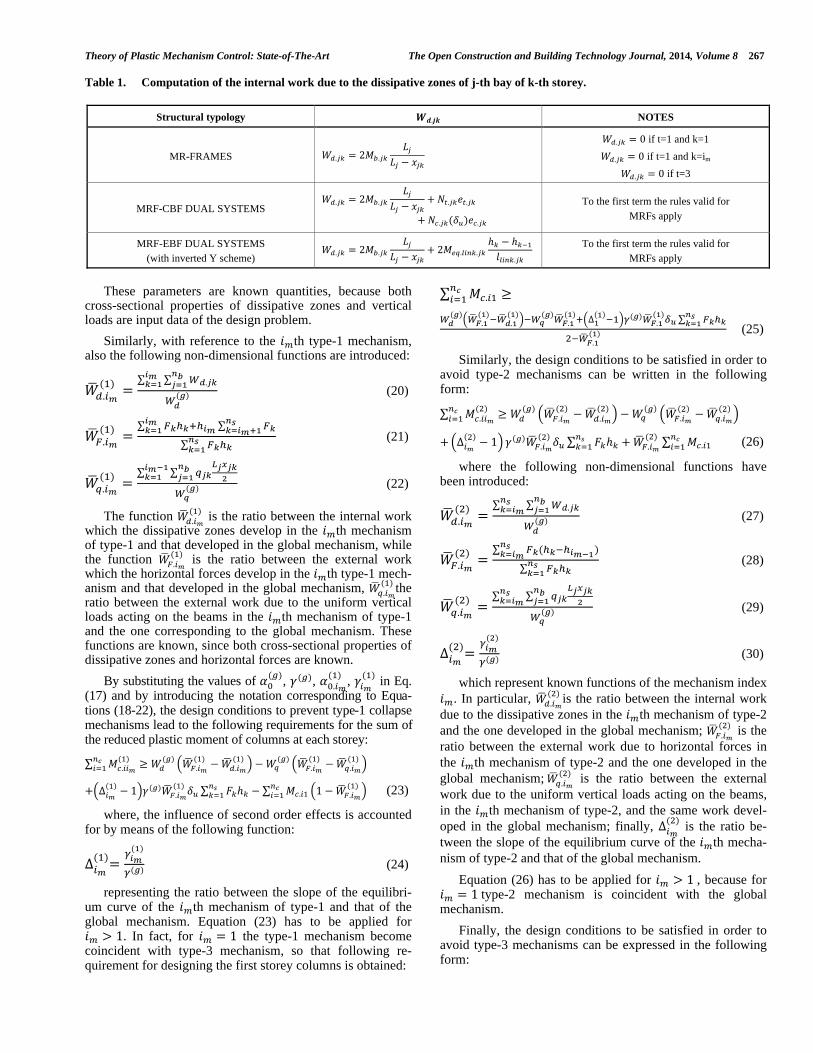
Regarding the internal work due to the dissipative zones of j-th bay of k-th storey, it has to be computed ac-counting for the features of the structural typology, as briefly summarised in Table 1.
In such table, represents the ultimate resistance of the yielded tensile diagonal of j-th braced bay and k-th storey and the corresponding axial plastic elongation due to a unit virtual rotation of the plastic hinges of first storey col-umns; is the post-buckling axial resistance of compressed diagonal computed as corresponding to the de-sign ultimate plastic top sway displacement and is the corresponding axial shortening due to a unit virtual rota-tion of the plastic hinges of first storey columns;
is the equivalent plastic moment of the link of j-th braced bay and k-th storey accounting for moment-shear interaction when needed [17] and is the correspond-ing link length.
2.3. Column Design Requirements to Prevent Undesired Collapse Mechanisms
The design conditions that column sections have to satis-fy in order to prevent the undesired failure modes can be derived by the direct application of TPMC, i.e. by explicat-ing the design conditions given by Eq. (17) as functions of the unknowns column plastic moments.
To this aim, the following notation is introduced:
(18)
which represents, in case of global mechanism and for a unit virtual rotation of column plastic hinges, the internal work due to the dissipative zones,
(19)
which represents, in case of global mechanism and for a unit virtual rotation of column plastic hinges, the external work due to the uniform loads acting on the beams.
Theory of Plastic Mechanism Control: State-of-The-Art The Open Construction and Building Technology Journal, 2014, Volume 8 267
Table 1. Computation of the internal work due to the dissipative zones of j-th bay of k-th storey.
Structural typology NOTES
MR-FRAMES
if t=1 and k=1
if t=1 and k=im
if t=3
MRF-CBF DUAL SYSTEMS
To the first term the rules valid for
MRFs apply
MRF-EBF DUAL SYSTEMS
(with inverted Y scheme)
To the first term the rules valid for
MRFs apply
These parameters are known quantities, because both
cross-sectional properties of dissipative zones and vertical loads are input data of the design problem.
Similarly, with reference to the th type-1 mechanism, also the following non-dimensional functions are introduced:
(20)
(21)
(22)
The function is the ratio between the internal work which the dissipative zones develop in the th mechanism of type-1 and that developed in the global mechanism, while the function is the ratio between the external work which the horizontal forces develop in the th type-1 mech-anism and that developed in the global mechanism, the ratio between the external work due to the uniform vertical loads acting on the beams in the th mechanism of type-1 and the one corresponding to the global mechanism. These functions are known, since both cross-sectional properties of dissipative zones and horizontal forces are known.
By substituting the values of , , , in Eq. (17) and by introducing the notation corresponding to Equa-tions (18-22), the design conditions to prevent type-1 collapse mechanisms lead to the following requirements for the sum of the reduced plastic moment of columns at each storey:
(23)
where, the influence of second order effects is accounted for by means of the following function:
(24)
representing the ratio between the slope of the equilibri-um curve of the th mechanism of type-1 and that of the global mechanism. Equation (23) has to be applied for
. In fact, for the type-1 mechanism become coincident with type-3 mechanism, so that following re-quirement for designing the first storey columns is obtained:
(25)
Similarly, the design conditions to be satisfied in order to avoid type-2 mechanisms can be written in the following form:
(26)
where the following non-dimensional functions have been introduced:
(27)
(28)
(29)
(30)
which represent known functions of the mechanism index
. In particular, is the ratio between the internal work
due to the dissipative zones in the th mechanism of type-2
and the one developed in the global mechanism; is the
ratio between the external work due to horizontal forces in
the th mechanism of type-2 and the one developed in the
global mechanism; is the ratio between the external
work due to the uniform vertical loads acting on the beams,
in the th mechanism of type-2, and the same work devel-
oped in the global mechanism; finally, is the ratio be-
tween the slope of the equilibrium curve of the th mecha-
nism of type-2 and that of the global mechanism.
Equation (26) has to be applied for , because for type-2 mechanism is coincident with the global
mechanism.
Finally, the design conditions to be satisfied in order to avoid type-3 mechanisms can be expressed in the following form:

268 The Open Construction and Building Technology Journal, 2014, Volume 8 Longo et al.
(31)
where the following non-dimensional functions have been introduced:
(32)
(33)
(34)
which represent known functions of the mechanism index . In particular, is the ratio between the internal work
due to the dissipative zones in the th mechanism of type-3 and the one developed in the global mechanism; is the ratio between the external work due to horizontal forces in the th mechanism of type-3 and the one developed in the global mechanism; finally, is the ratio between the slope of the equilibrium curve of the th mechanism of type-2 and that of the global mechanism.
It is useful to note that Eq.(31), for , provides:
(35)
which is coincident with Eq.(25), because for t=1 and and t=3 and the two collapse mechanisms are
coincident, so that:
(36)
which represent known functions of the mechanism index .
TPMC was originally developed in nineties, so that the design conditions given by Eq. (17) do not constitute any new. However, the original work was devoted to MRFs only and based on an iterative procedure, so that the application of TPMC required the development of specific computer pro-grams. The advances presented in this paper provide, on one hand, an unitary presentation dealing with MRFs, MRF-EBF dual systems and MRF-CBF dual systems and, on the other hand, provide a closed form solution starting from the obser-vation that type-1 mechanism and type-3 mechanism for
are coincident, while type-2 mechanism for is just the desired mechanism, i.e. the global one. Therefore, Eq. (25) or Eq. (35) can be used to design the first storey columns. As soon as the first storey columns have been de-signed, Equations (23), (26) and (31) provide, at all the other storeys, the column sections required to avoid any undesired
collapse mechanism. The resulting design procedure is now extremely simple and well suited even for hand calculations. The algorithm of the new procedure to design structures col-lapsing with a global mechanism is reported in Fig. (3).
3. WORKED EXAMPLE
The design procedure briefly summarized in Fig. (3) has been applied to design a building, whose geometrical scheme is depicted in Fig. (4), with reference to four different struc-tural seismic-resistant systems. The structural typologies herein investigated are a MR-Frame, two MRF-CBF dual systems, one with X-braces and one with V-braces, respec-tively, and a MRF-EBF dual system with inverted Y-scheme.
Reference is made to a residential building. The charac-teristic values of dead and live loads are, respectively, equal to and . The design val-ues of horizontal seismic forces have been derived with ref-erence to the design spectrum for stiff soil conditions sug-gested by Eurocode 8 for stiff soil conditions (soil type A) and by assuming a behaviour factor, , equal to 6 for the MR-Frame and for the MRF-EBF dual system and equal to 4.8 for the MRF-CBF dual systems. The material adopted for the structure is steel grade S275. With reference to the pe-rimeter frame pointed out in Fig. (4), the analysed structural schemes are shown in Fig. (5).
The beam sections resulting from the design procedure are delivered in Table 2.
Regarding the bracing members of MRF-CBF dual sys-tems, they have been considered as dissipative members and have been designed to withstand the whole seismic design forces. This criterion is justified considering that it is the most efficient way to reduce interstorey drifts as required to fulfil also serviceability limit state requirements. In particu-lar, in the case of MRF-CBF dual system with X-braces, only the tensile diagonals are considered active to evaluate their design axial forces, whereas, in the case of MRF-CBF dual system with V-braces both tensile and compressed di-agonal are considered to withstand the horizontal seismic forces. The slenderness limitation required by Eurocode 8 [11] have been also considered.
Concerning the diagonal members of the MRF-EBF dual system with inverted Y-scheme, they have to be considered non dissipative members, so that they have been designed to withstand the axial forces transmitted by the yielded and strain-hardened links in their ultimate conditions. In addition such diagonal members have to be also checked against both in-plane and out-of-plane buckling. The sections of diagonal members selected from CHS standard shapes are reported in Table 3.
Finally, with reference to the MRF-EBF dual system with inverted Y-scheme, link sections have been dimensioned to withstand the whole storey seismic shear. Only short links have been adopted [11, 17]. The sections selected from standard shapes are provided in Table 4.
Finally, the column sections needed to prevent undesired collapse mechanisms have been derived by means of the design procedure briefly summarized in Fig. (3). The result-ing column sections are delivered in Table 5.

Theory of Plastic Mechanism Control: State-of-The-Art The Open Construction and Building Technology Journal, 2014, Volume 8 269
Fig. (3). Design algorithm of TPMC.
Fig. (4). Plan layout of the analysed buildings.

270 The Open Construction and Building Technology Journal, 2014, Volume 8 Longo et al.
Table 2. Beam sections.
Storey
MR-Frames MRF-EBF dual system MRF-CBF X-braced MRF-CBF V-braced
External
beams
Internal
beam
External
beams
Internal
beam
External
beams
Internal
beam
External
beams
Internal
beam
1 IPE 300 IPE 400 IPE 180 IPE 240 IPE 180 IPE 240 IPE 180 HE 360 B
2 IPE 300 IPE 400 IPE 180 IPE 240 IPE 180 IPE 240 IPE 180 HE 360 B
3 IPE 300 IPE 400 IPE 180 IPE 240 IPE 180 IPE 240 IPE 180 HE 360 B
4 IPE 300 IPE 400 IPE 180 IPE 240 IPE 180 IPE 240 IPE 180 HE 360 B
5 IPE 300 IPE 400 IPE 180 IPE 240 IPE 180 IPE 240 IPE 180 HE 340 B
6 IPE 300 IPE 400 IPE 180 IPE 240 IPE 180 IPE 240 IPE 180 HE 320 B
7 IPE 300 IPE 400 IPE 180 IPE 240 IPE 180 IPE 240 IPE 180 HE 320 B
8 IPE 300 IPE 400 IPE 180 IPE 240 IPE 180 IPE 240 IPE 180 HE 280 B
Fig. (5). Structural schemes of the analysed perimeter frames.

Theory of Plastic Mechanism Control: State-of-The-Art The Open Construction and Building Technology Journal, 2014, Volume 8 271
Table 3. Diagonal members.
Storey
MRF-EBF dual system MRF-CBF X-braced MRF-CBF V-braced
Diagonal section Diagonal section Diagonal section
1 CHS 244.5x12.5 0.264 CHS 121.0x6.0 1.90 CHS 127.0x6.0 0.795
2 CHS 244.5x12.5 0.264 CHS 121.0x6.0 1.90 CHS 127.0x6.0 0.795
3 CHS 244.5x12.5 0.264 CHS 121.0x6.0 1.90 CHS 121.0x6.0 0.841
4 CHS 244.5x12.5 0.264 CHS 121.0x5.0 1.88 CHS 121.0x6.0 0.891
5 CHS 244.5x12.5 0.264 CHS 121.0x5.0 1.88 CHS 114.3x6.0 0.931
6 CHS 244.5x12.5 0.264 CHS 121.0x4.0 1.87 CHS 114.3x5.0 1.071
7 CHS 244.5x12.5 0.264 CHS 114.3x3.0 1.96 CHS 108.0x4.0 1.181
8 CHS 244.5x12.5 0.264 CHS 114.3x2.5 1.96 CHS 108.0x2.0 1.316
Table 4. Link members.
Storey MRF-EBF dual system
Link sections (m)
1 HE 160 B 0.50
2 HE 160 B 0.50
3 HE 160 B 0.50
4 HE 160 B 0.50
5 HE 140 B 0.50
6 HE 120 B 0.50
7 HE 120 B 0.50
8 HE 120 B 0.50
Table 5. Final results of TPMC.
Storey
MR-Frame MRF-EBF dual system MRF-CBF X-braced MRF-CBF V-braced
C1 C2 C1 C2 C1 C2 C1 C2
1 HE 400 B HE 450 B HE 220 B HE 320 B HE 200 B HE 500 B HE 220 B HE 450 B
2 HE 400 B HE 450 B HE 200 B HE 300 B HE 200 B HE 450 B HE 220 B HE 450 B
3 HE 400 B HE 450 B HE 200 B HE 300 B HE 200 B HE 400 B HE 220 B HE 400 B
4 HE 400 B HE 450 B HE 200 B HE 300 B HE 200 B HE 400 B HE 220 B HE 400 B
5 HE 400 B HE 450 B HE 200 B HE 300 B HE 200 B HE 340 B HE 200 B HE 340 B
6 HE 400 B HE 400 B HE 200 B HE 300 B HE 180 B HE 300 B HE 200 B HE 300 B
7 HE 340 B HE 340 B HE 200 B HE 280 B HE 160 B HE 260 B HE 180 B HE 280 B
8 HE 260 B HE 280 B HE 160 B HE 180 B HE 100 B HE 160 B HE 120 B HE 160 B
4. VALIDATION OF THE DESIGN PROCEDURE
In order to validate the design procedure, both static non linear analyses (push-over) and incremental dynamic non-linear analyses have been carried out by means of SAP 2000 computer program, to investigate the actual seismic response of the designed frame. These analyses have the primary aim
to confirm the development of the desired collapse mecha-nism typology and to evaluate the obtained energy dissipa-tion capacity, testing the accuracy of the proposed design methodology. In addition, by means of a specifically devel-oped post-processor, out-of-plane stability checks of com-pressed members have been performed for each step of the nonlinear analysis. Second order effects due to vertical loads

272 The Open Construction and Building Technology Journal, 2014, Volume 8 Longo et al.
have been accounted for, including also second order effects due to the inner part of the building having gravity columns. To this aim a leaning column has been included in the model (Fig. 5).
Structural members have been modelled by means of nonlinear elements. More precisely, beams and columns have been modelled using beam-column elements with the possibility of developing plastic hinges at their ends. The interaction between axial force and bending moment has been accounted for by means of the relevant M-N plastic domain. A rigid perfectly plastic behaviour has been as-sumed for such hinges.
Diagonal braces of MRF-CBF dual systems have been modelled accounting both for the possibility of yielding in tension and for the occurrence of buckling in compression. To this aim diagonals have been modelled by means of two beam-column elements whose common intermediate node has an initial displacement properly evaluated to model the effects of geometrical and mechanical imperfections. In par-ticular, the magnitude of such equivalent geometrical imper-fection has been computed according to the corresponding buckling curve of Eurocode 3 [30]. Moreover, flexural yield-ing of diagonal members due to buckling has been modelled by means of fiber plastic hinge elements.
As the diagonal braces of the MRF-EBF dual system are designed to guarantee that buckling is prevented, they have been modelled by means beam-column elements with the possibility of developing plastic hinges at their ends.
In Fig. (6), the push-over curves providing the horizontal force multiplier versus the top sway displacement obtained
from the nonlinear analyses are depicted. In addition, two straight lines corresponding, respectively, to the linear elastic analysis and to the global mechanism equilibrium curve are also plotted. The comparison between the linearised mecha-nism equilibrium curves and the softening branch of the push-over curves provides a first confirmation about the ac-curacy of the design methodology.
Moreover, in Fig. (7) the pattern of yielding developed at the design ultimate top sway displacement is depicted. Plas-tic hinges occurring in beams and columns are pointed out and the yielding of diagonals in tension and buckling of compressed ones are also properly represented.
The most important validation of the proposed design procedure regards the check of the fulfilment of the design goal, given by the yielding of all the dissipative elements according to the collapse mechanism of global type. In fact, plastic hinges in columns develop only at the base of the first storey. Even though the collapse mechanism is not complete-ly developed when the ultimate design top sway displace-ment is reached, the pattern of yielding is in perfect agree-ment with the global mechanism.
A great number of structural schemes have been ana-lysed, with different number of storeys and different geomet-rical configurations. The push-over analyses have always confirmed the results which are, for sake of shortness, herein illustrated with reference to one scheme only for each struc-tural typology.
Aiming to provide a further validation of the proposed design procedure, the seismic response of the designed struc-tures has been investigated by means of nonlinear dynamic
Fig. (6). Behavioural curves of the designed frames and comparison with the corresponding bilinear approximation.

Theory of Plastic Mechanism Control: State-of-The-Art The Open Construction and Building Technology Journal, 2014, Volume 8 273
analyses carried out using SAP2000 computer program [31] considering the same structural models already adopted for push-over analyses.
Fig. (7). Developed pattern of yielding.
The modelling of the cyclic response of braces of MRF-
CBF dual systems results from the cyclic response of the fiber plastic hinge element located at the their mid-span where, as already stated, also an initial imperfection is pro-vided to model the occurrence of buckling. In order to show the accuracy of the modelling of cyclic behaviour of diago-nal braces by means of the fiber model of SAP 2000 com-puter program [31], in Fig. (8) [36] the comparison between the predicted cyclic response and the experimental test re-sults has been carried out with reference to a specimen tested in [32-35].
Fig. (8). Comparison between experimental and theoretical curve.
Dealing with IDA analyses, the integration of motion equations has been carried out by means of Hilber-Hughes-Taylor -method. In addition, P- effects in large displace-ment formulation are also considered. Moreover, 5% damp-ing according to Rayleigh has been assumed with the propor-tionality factors computed with reference to the first and the third mode of vibration. Finally, by means of a specifically developed post-processor, out-of-plane stability checks of compressed members have been carried out for each step of the analysis according to Eurocode 3 formulations [30].
The results of such investigation are presented with ref-erence to a deterministic analysis carried out considering the set of historical ground motion records reported in Table 6. Incremental Dynamic Analyses (IDA) [37], have been car-ried out by scaling all the records (Fig. 9) to provide increas-ing values of the spectral acceleration Sa(T1) corresponding to the fundamental period of vibration of the structure T1.
Moreover, in Table 7, for the four analysed structures, the vibration periods of the first 8 modes and the correspond-ing participation factors are delivered.
Dealing with seismic performance assessment, the IDA analyses have been carried out until the occurrence of one of the following limit states:
1) out-of-plane buckling of columns;
2) attainment of a plastic rotation demand, at the beam ends or at the link ends, equal or exceeding a given local duc-tility supply. Such local ductility supply has been as-sumed equal to 0.04 rad for the beam plastic hinges and equal to 0.14 rad with reference to the link ends. This last value (for MRF-EBF scheme) corresponds to a maximum interstorey drift equal to 0.023 rad;
3) attainment of a plastic rotation demand at the base of first storey columns exceeding a given local ductility supply;
4) fracture of diagonal braces (only in the case of CBF-MRF dual systems);
In Fig. (10), the IDA curves providing the Maximum In-terstorey Drift Ratio (MIDR) as a function of the spectral acceleration are reported for each examined structure. These curves appear regular and increasing for each structural ty-pology and do not exhibit dynamic instability effects. In ad-dition, the average collapse value in term of spectral acceler-ation and peak ground acceleration for each structure are reported in Table 8 for each ground motion. It is useful to note that the structure exhibiting the highest performance is the MRF-CBF dual system with X-braces, in terms of ulti-mate spectral acceleration, while is the MR-Frame, in terms of Peak Ground Acceleration.
Finally, in order to show the damage distribution, in Fig. (11) the Peak Interstorey Drift Ratios (PIDR) versus storey level are depicted for each structure designed by means of TPMC. These figures are referred to a spectral ac-celeration value very close to the one corresponding to the occurrence of the ultimate MIDR value. It is possible to ob-serve that the distribution of damage is quite uniform; this is because the proposed procedure, leading to structures failing in global mode, assures that the drift demand does not con-centrate in specific storeys.

274 The Open Construction and Building Technology Journal, 2014, Volume 8 Longo et al.
Table 6. Set of historical ground motions used for IDA.
N Record Date Component Sa(T=0.97)/g Sa(T=0.93)/g amax/g length [sec]
1 GAZLI USSR (Karakyr) 17/05/1976 N-S 0.812 0.823 0.608 16.25
2 HELENA MONTANA (Carrol College) 31/10/1935 E-W 0.185 0.178 0.153 9.67
3 KEN-OKI (Miyagi) 1978 N-S 0.109 0.124 0.140 58.00
4 OLYMPIA 13/04/1949 N-E 0.226 0.227 0.325 30.28
5 TAFT 21/07/1952 N-W 0.168 0.206 0.157 30.00
6 TOKYO 1956 N-S 0.084 0.091 0.075 11.40
7 VERNON 10/03/1933 S-E 0.159 0.159 0.192 42.17
Fig. (9). Ground motions spectra scaled to the same spectral acceleration at T = 0.93 s.
Table 7. Period of vibration of the designed structures and participation factors.
MODE
MR-Frames MRF-EBF Dual System MRF-CBF X-braced MRF-CBF V-braced
Period
(s)
Participation
Factor
(kN/s2)
Period
(s)
Participation
Factor (kN/s2)
Period
(s)
Participation
Factor (kN/s2)
Period
(s)
Participation
Factor (kN/s2)
1 1.57055 0.77508 1.04145 0.77392 0.93050 0.16890 0.85 0.75
2 0.50009 0.10896 0.37078 0.14376 0.32410 0.07670 0.33 0.14
3 0.27948 0.04651 0.23006 0.03550 0.18300 0.04040 0.21 0.04
4 0.19166 0.02728 0.18827 0.01688 0.15890 0.00330 0.17 0.02
5 0.17459 0.00000 0.16670 0.00952 0.15610 0.00091 0.15 0.01
6 0.14839 0.01794 0.15317 0.00645 0.15480 0.00184 0.15 0.00
7 0.12434 0.01230 0.14348 0.00470 0.15450 0.00386 0.14 0.01
8 0.10962 0.00760 0.13678 0.00238 0.15330 0.00173 0.14 0.01

Theory of Plastic Mechanism Control: State-of-The-Art The Open Construction and Building Technology Journal, 2014, Volume 8 275
Fig. (10). IDA curves providing MIDR versus spectral acceleration.
Table 8. Sa and PGA values corresponding to attainment of the collapse condition for the examined structures.
MR-Frames MRF-EBF
dual system
MRF-CBF
X-braced
MRF-CBF
V-braced
RECORD
GAZLI USSR (Karakyr) 1.50 1.71 1.30 0.98 1.80 1.32 1.70 1.29
HELENA MONTANA 0.90 1.19 0.90 0.72 0.90 0.76 1.20 0.96
KEN-OKI (Miyagi) 0.70 2.63 1.00 1.50 1.50 1.76 1.30 1.95
OLYMPIA 0.80 2.40 1.00 1.44 1.05 1.51 1.10 1.59
TAFT 1.40 1.27 0.70 0.82 1.30 1.01 1.10 1.33
TOKYO 0.90 2.30 1.40 1.35 1.30 1.10 0.80 0.94
VERNON 1.00 1.44 0.70 0.85 1.25 1.51 0.80 0.77
MEAN VALUE 1.03 1.84 0.86 1.09 1.30 1.28 1.14 1.26
A brief summary of results obtained by means of IDA
analyses is provided in Table 8 where the values of both peak ground acceleration and spectral acceleration leading to the attainment of the assumed ultimate conditions are given. All the designed structural solutions provide excellent seis-mic performances because of the high values of the seismic intensity measure corresponding to the occurrence of ulti-mate conditions. This is due to the rigorous control of the plastic mechanism. However, it can be observed that, if ref-erence is made to the spectral acceleration, the best seismic
performance is obtained by means of MRF-CBF dual sys-tems with the X-scheme providing an ultimate spectral ac-celeration value slightly greater than the one exhibited in the case of V-scheme. Conversely, the worst result is obtained in the case of MRF-EBF dual system, because the high local ductility demand occurring in link elements, despite their high capacity, does not allow the complete exploitation of the plastic reserves due to the moment-resisting part of the structural scheme.

276 The Open Construction and Building Technology Journal, 2014, Volume 8 Longo et al.
Fig. (11). PIDR vs Storey level.
It is also interesting to point out that, if reference is made
to the peak ground acceleration leading to ultimate condi-tions, the best seismic performance is gained by means of the MR-Frame, because, due to its high lateral deformability compared to dual systems, the increase of the period of vi-bration leads to a significant increase of the PGA value cor-responding to the attainment of the spectral acceleration val-ue leading to collapse.
5. STRUCTURAL WEIGHT AND ECONOMIC ISSUES
Finally, aiming to a more complete comparison between the considered design seismic resistant typologies, also some economic considerations can be made.
It is preliminarily assumed that the cost, , of Whole Structural System (WSS) is proportional to its weight, , by means of the factor :
(37)
(38)
where the second index denotes the structural typology (i.e. the index MRF to identify the MR-Frame and the index DUAL to identify dual systems, either MRF-EBF or MRF-CBF both X-braced and V-braced).
From the above equations, the cost of whole structural system with respect to the building with seismic-resistant structural system based on MR-Frame can be expressed as:
(39)
According to the common design experience, it can be also assumed that the cost of the whole structural system represents a given percentage of the cost of the Whole Build-ing (WB) depending on its intended use:
(40)
The cost of the Non Structural Components (NSC) is the difference between the cost of the whole building and the one of the whole structural system and it can be expressed as:
(41)
Such cost is independent of the structural typologies used as resisting system and, therefore, it is valid for all the build-ings designed. As a consequence, by summing the cost of the structural part (39) to the cost of nonstructural components (41), the cost of the whole building can be related to the one of the building with MR-Frame seismic-resistant structural system as follows:
(42)
In the examined study case, the weight of the Seismic Load Resisting System (SLRS) which includes all the 4 pe-rimeter seismic resisting system as depicted in Fig. (4), for each considered structural typology (MRF-EBF, MRF-CBF X-braced and V-braced), is reported in Table 9 where:
is the ratio between the weight of the Seismic Load Resisting System (SLRS) for the dual sys-

Theory of Plastic Mechanism Control: State-of-The-Art The Open Construction and Building Technology Journal, 2014, Volume 8 277
tem and the same weight when the seismic-resistant structur-al system based on MR-Frame is adopted;
is the ratio between the weight of the whole structural system for the dual system and the same weight when the seismic-resistant structural system based on MR-Frame is adopted;
is the ratio between the cost of the whole building (WB) for the dual system and the same weight when the seismic-resistant structural system based on MR-Frame is adopted. The cost of the whole building is computed using the same expression reported in Eq. (42) where the coefficient has been assumed equal to 0.30 as a typical value occurring for residential buildings in Italy.
Table 9 points out that, in the examined case, the use of an MRF-EBF dual system with inverted Y-scheme as Seis-mic Load Resisting System leads to 26.0% decrease of struc-tural weight with respect to the MR-Frame structure, while in case MRF-CBF dual systems it is possible to obtain a de-crease in term of weight equal to 36.0% and 15.0% for X-braced and V-braced schemes, respectively.
However, as SLRS is only a part of whole structural sys-tem (WSS), such percentages reduce considering also the structural weight due to the Gravity Load Carrying Frames (GLCF), WGLCF= 675.5 kN, in the examined cases, as it is possible to note in Table 9.
Regarding the decrease in term of cost of the whole building (WB) evaluated by means of Eq. (42) the reduction ranges from 3% in the case of MRF-CBF dual system with V-braced scheme to 6% in the case of MRF-CBF dual sys-tem with X-braced scheme.
CONCLUSION
In this paper, the Theory of Plastic Mechanism Control has been applied to different perimeter seismic resistant structures. In particular, the application of the proposed de-sign approach has been presented with reference to a case study constituted by a three-bay eight-storey building. The accuracy of the design methodology has been primarily checked by means of push-over analyses whereas the defini-tive validation has been performed by means of Incremental Dynamic Analyses. The results obtained are in perfect agreement with the design goal, because the development of undesired partial mechanisms is prevented and the develop-ment of a global type mechanism is assured for each struc-tural typology.
Both push-over and dynamic analyses show that struc-tures designed according to TPMC are characterised by the
possibility to withstand high values of the spectral accelera-tion. The value of the spectral acceleration corresponding to the collapse prevention limit state obtained for the analysed building is equal to 1.03 g for MR-Frame, 0.86 g for MRF-EBF dual system, 1.30 g for MRF-CBF X-braced and 1.14 g for MRF-CBF V-braced. These values are obtained with reference to buildings with the same geometrical scheme and design with the same criteria, i.e. by means of TPMC. There-fore, the differences resulting from the seismic response ob-tained can be attributed to the influence of the seismic re-sistant scheme only. In other words, the differences between the seismic performances obtained are due to the structural typology only. In particular, in terms of spectral acceleration the MRF-CBF X-Braced scheme exhibits the highest value while the MRF-EBF dual system shows the lowest value. This is due to the influence of the link rotational capacity which corresponds to a maximum interstorey drift equal to 0.023 rad and, therefore, less than the one (0.04 rad) which can be achieved when the plastic rotation capacity of beams can be fully exploited. Conversely, if reference is made to the peak ground acceleration, the best seismic performance is gained by means of the MR-Frame, because, due to its high lateral deformability compared to dual systems, the benefits coming from the increase of the period of vibration can be exploited.
The comparison in term of structural weight leads, in case of dual systems, to lighter structures if compared with the MR-Frame. This result is due to the need to fulfil ser-viceability requirements. Such need, in the case of the MR-Frame, leads to the increase of beam sections and conse-quently also of the column sections required to assure the development of the desired collapse mechanism, i.e. the global one.
The above results do not have a general validity, because resulting from a preliminary investigation dealing with only one geometrical scheme. Therefore, the future developments of the research reported in this paper, dealing with structures designed by a common approach, i.e. TPMC, will need the extension of the comparison to a sufficient number of struc-tural scheme, before gaining general conclusions.
In addition, it has to be recognized that seismic response of structures is highly affected by the frequency content of the ground motion, so that record-to-record variability has to be more accurately considered. Therefore, the future devel-opment of the work will require also the application of a probabilistic approach [38-41] to evaluate the seismic relia-bility in terms of mean annual frequency of exceeding speci-fied limit states.
Table 9. Weight and cost ratios of the examined structural typologies.
Structural typology [kN]
MRF 208.74 1.00 1.00 1.00
MRF-EBF dual system 155.68 0.74 0.86 0.96
MRF-CBF X-braced 134.00 0.64 0.80 0.94
MRF-CBF V-braced 178.48 0.85 0.92 0.97

278 The Open Construction and Building Technology Journal, 2014, Volume 8 Longo et al.
CONFLICT OF INTEREST
The authors confirm that this article content has no con-flict of interest.
ACKNOWLEDGEMENTS
Declared none.
REFERENCES
[1] R. Park: “Ductile design approach for reinforced concrete frames”, Earthquake Spectra, EERI, vol. 2, no. 3, pp. 565-619, 1986.
[2] F.M. Mazzolani, and V. Piluso, “Theory and Design of Seismic Resistant Steel Frames”, E&FN Spon, An Imprint of Chapman and Hall, 1996.
[3] M. Bruneau, C.M. Uang, and R.S.E. Sabelli, “Ductile Design of Steel Structures”, McGraw-Hill USA, 2011.
[4] H. Akiyama, “Earthquake Resistant Limit State Design for Build-ing”, University of Tokyo Press, Tokyo, 1985.
[5] E. Rosenblueth (ed.), “Design of Earthquake Resistant Structures”, Pentech Press, London, 1980.
[6] D.J. Dowrich, “Earthquake Resistant Design”, A manual for engi-neers and architects, Wiley, New York, 1977.
[7] T. Paulay, and M.J.N. Priestley, “Seismic Design of Reinforced Concrete and Masonry Buildings”, Wiley, New York, 1995.
[8] M. Wakabayashi, “Design of Earthquake Resistant Buildings”, McGraw-Hill, New York, 1986, p. 229.
[9] V. V. Bertero, and E. P. Popov, “Seismic Behaviour of Ductile Moment-resisting Reinforced Concrete Frames”, In: Reinforced Concrete Structures in Seismic Zones, ACI Publication SP-53, American Concrete Institute, Detroit, 1977, pp. 247-91.
[10] H.S. Lee, “Revised rule for concept of strong-column weak-girder design”, Journal of Structural Engineering, ASCE, vol. 122, pp. 359-364, 1996.
[11] EN 1998-1: “Eurocode 8: Design of Structures for Earthquake Resistance – Part 1: General Rules, Seismic Actions and Rules for Buildings”, CEN, 2004
[12] ANSI/AISC 341-10, “Seismic provisions for structural steel build-ings”, American Institute of Steel Construction, 2010.
[13] NTC 2008 - D.M. 14 Gennaio 2008: «Nuove Norme Tecniche per le Costruzioni» (Italian Seismic Code).
[14] F.M. Mazzolani, and V. Piluso, “Plastic design of seismic resistant steel frames”, Earthquake Engineering and Structural Dynamics, vol. 26, pp. 167-91, 1997.
[15] R. Montuori, and V. Piluso, “Design of Semi-Rigid steel frames for failure mode control”, Moment Resistant Connections of Steel Frames: Design and Reliability, London: E&FN Spon, Taylor & Francis Group, pp. 461-83, 2000.
[16] L. Mastandrea, E. Nastri, and V. Piluso, “Validation of a design procedure for failure mode control of EB-Frames: Push-over and IDA analyses”, The Open Construction and Building Technology Journal, vol. 7, pp. 193-207, 2013.
[17] R. Montuori, E. Nastri, and V. Piluso, “Rigid-plastic analysis and moment–shear interaction for hierarchy criteria of inverted Y EB-Frames”, Journal of Constructional Steel Research, vol. 95, pp. 71-80, 2014.
[18] R. Montuori, E. Nastri, and V. Piluso, “Theory of plastic mecha-nism control for eccentrically braced frames with inverted Y-scheme”, Journal of Constructional Steel Research, vol. 93, pp. 122-35, 2014.
[19] R. Montuori, E. Nastri, and V. Piluso, “Theory of plastic mecha-nism control for the seismic deisgn of braced equipped with friction dampers”, Mechanics Research Communication, vol. 58, pp. 112-23, 2014.
[20] M.A. Conti, L. Mastandrea, and V. Piluso, “Plastic design and seismic response of knee braced frames”, Advanced Steel Costruc-tions, vol. 5, pp. 343-63, 2009.
[21] A. Longo, R. Montuori, and V. Piluso, “Theory of plastic mecha-nism control of dissipative truss moment frames”, Engineering Strucutures, vol. 37, pp. 63-75, 2012.
[22] Longo, R. Montuori, and V. Piluso, “Failure mode control and seismic response of dissipative truss moment frames”, Journal of Structural Engineering, vol. 138, pp. 1388-97, 2012.
[23] Longo, R. Montuori, and V. Piluso, “Theory of plastic mechanism control for MRF-CBF dual systems and its validation”, Bulletin of Earthquake Engineering, vol. 12, pp. 2405-18, 2014.
[24] M.T. Giugliano, A. Longo, R. Montuori, and V. Piluso, “Failure mode and drift control of MRF-CBF dual systems”, The Open Journal of Construction and Building Technology, vol. 4, pp.121-133, 2010.
[25] A. Longo, R. Montuori, and V. Piluso, “Moment Frames – concen-trically braced frames dual system: Analysis of different design cri-teria”, Structure and Infrastructure Engineering, 2015 (in press).
[26] A. Longo, R. Montuori, E. Nastri, and V. Piluso, “On the use of HSS in seismic resistant structures”, Journal of Costructional Steel Research, vol. 103, pp. 1-12, 2014.
[27] R. Montuori, E. Nastri, and V. Piluso, “Advances in theory of plastic mechanism control: Closed form solution for MR-Frames”, Earthquake Engineering and Structural Dynamics, 2015 (in press).
[28] A. Longo, R. Montuori, and V. Piluso, “Plastic design of seismic resistant V-Braced frames”, Journal of Earthquake Engineering, vol. 12, 1246-66, 2008.
[29] A. Longo, R. Montuori, and V. Piluso, “Failure mode control of X braced frames under seismic actions”, Journal of Earthquake Engi-neering, vol. 12, 728-59, 2008.
[30] CEN. 2005. EN 1993-1-1-Eurocode 3: “Design of Steel Structures. Part 1: General Rules and Rules for Buildings”, Comité Européen de Normalisation, 2005.
[31] CSI 2007. SAP 2000: “Integrated Finite Element Analysis and Design of Structures”, Analysis Reference. Computer and Structure Inc., University of California, Berkeley, 1995.
[32] S. B. Oreste, “Pseudodynamic testing of strain-softening systems with adaptive time steps”, Earthquake Engineering and Structural Dynamics, vol. 23, pp. 745-60.
[33] A.M. Kanvinde, and G.G. Deierlein, “Micromechanical simulation of earthquake induced fracture in steel structures”, Blume Center TR145. http://cee.engr. ucdavis.edu/faculty/kanvinde/1se05-6038.pdf. 2004.
[34] B.V. Fell, A.T. Myers, and G.G. Deierlein, and A.M. Kanvinde. Testing and simulation of ultra-low cycle fatigue and fracture in steel braces. http://cee.engr.ucdavis.edu/ faculty/kanvinde/ 8nceepaper.pdf. AC. 2005.
[35] B.V. Fell, A.T. Myers, G.G. Deierlein and, A.M. Kanvinde, “Test-ing and simulation in steel braces”, Paper presented at: The Con-ference 8th U.S. National Conference on Earthquake Engineering, San Francisco, April, 2006.
[36] M.T. Giugliano, A. Longo, R. Montuori, and V. Piluso, “Plastic design of CB-frames with reduced section solution for bracing members”, Journal of Constructional Steel Research, vol. 66, pp. 611-21, 2010.
[37] Pacific Earthquake Engineering Research Center, PEER Strong Motion Database, http://peer.berkley.edu.smcat.
[38] A. Longo, R. Montuori, and V. Piluso, “Influence of design criteria on the seismic reliability of X-braced frames”, Journal of Earth-quake Engineering, vol. 12, pp. 406-31, 2008.
[39] A. Longo, R. Montuori, and V. Piluso, “Seismic reliability of V-braced frames: influence of design methodologies”, Earthquake Engineering and Structural Dynamics, vol. 38, pp. 1587-608, 2009.
[40] A. Longo, R. Montuori, and V. Piluso, “Seismic reliability of chev-ron braced frames with innovative conception of bracing mem-bers”, Advanced Steel Construction, an International Journal, vol. 5, 2009 http://dx.doi.org/10.1080/13632460701457231.
[41] M.T. Giugliano, A. Longo, R. Montuori, and V. Piluso, “Seismic reliability of traditional and innovative concentrically braced frames”, Earthquake Engineering & Structural Dynamics, vol. 40, pp. 1455-74, 2011.
Received: July 30, 2014 Revised: September 10, 2014 Accepted: October 15, 2014
© Longo et al.; Licensee Bentham Open.
This is an open access article licensed under the terms of the Creative Commons Attribution Non-Commercial License (http://creativecommons.org/-
licenses/by-nc/3.0/) which permits unrestricted, non-commercial use, distribution and reproduction in any medium, provided the work is properly cited.