27– 512 mhz base station antennas for mobile · pdf fileinclude the static mechanical...
TRANSCRIPT

27 – 512 MHzBase Station Antennasfor Mobile Communications
Antennen · Electronic
2
Photo on title page: 3-Sector Tetra Base Station
Catalogue Issue 09/00
All data published in previous catalogue issues hereby becomes invalid.We reserve the right to make alterations in accordance with the requirements of our customers.
Please note:
As a result of ever more stringent legal regulations and judgements regarding product liability, we are obligedto point out certain risks that may arise when products are used under extraordinary operating conditions.
The mechanical design is based on the environmental conditions as stipulated in ETS 300 019–1–4, whichinclude the static mechanical load imposed on an antenna by wind at maximum velocity.
Extraordinary operating conditions, such as heavy icing or exceptional dynamic stress (e. g. strain caused by oscillating support structures), may result in the breakage of an antenna or even cause it to fall to the ground.
These facts must be considered during the site planning process.
The details given in our data sheets have to be followed carefully when installing the antennas andaccessories.
The installtion team must be properly qualified and also be familiar with the relevant national safetyregulations.
List of available catalogues forMobile Communicatio n Antennas an d Accessories
– 790 – 2200 MHz Base Statio n Antennas– 27 – 512 MHz Base Statio n Antennas
– Ground-to-Air Communicatio n Antennas
– Railway Communicatio n Antennas
– 80/160 MHz Filte r, Combiners , Amplifiers for Mobile Communications– 450 MHz Filters, Combiners , Amplifiers for Mobile Communications– 900/1800 MHz Filters, Combiners , Amplifiers for Mobile Communications
The listed catalogues
are also
available on CD-ROM
“Quality leads the way”Being the oldest and largest antenna manufacturer worldwide, we take on every daythe challenge arising from our own motto. One of our basic principles is to look alwaysfor the best solution in order to satisfy our customers.Our quality assurance system conforms to DIN EN ISO 9001 and applies to the productrange of the company: Antenna systems, communication products as well as activeand passive distribution equipment.
3
Omnidirectional Antennas 27 – 87.5 MHz
Directional Antennas 68 – 87.5 MHz
Directional Antennas 146 – 174 MHz
Technical Supplement
Omnidirectional Antennas 146 – 174 MHz
Omnidirectional Antennas 370 – 470 MHz
Directional Antennas 360 – 512 MHz
Power Splitters
Accessories
4
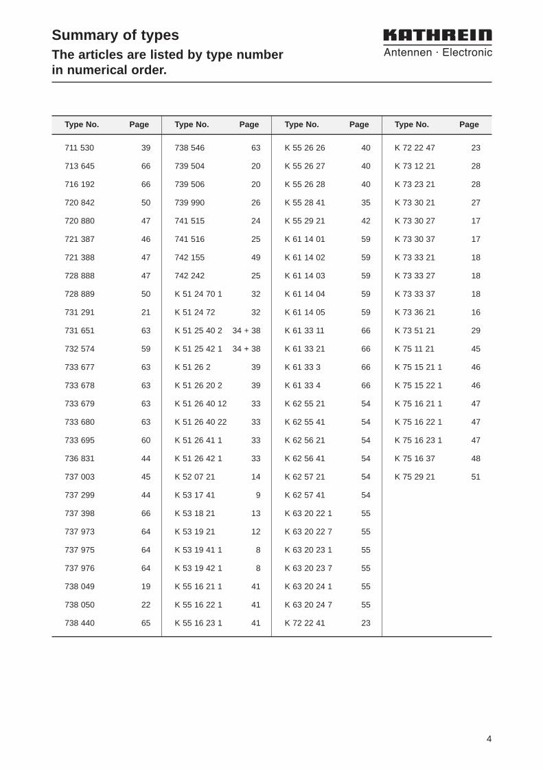
Summary of typesThe articles are listed by type numberin numerical order.
738 546 63
739 504 20
739 506 20
739 990 26
741 515 24
741 516 25
742 155 49
742 242 25
K 51 24 70 1 32
K 51 24 72 32
K 51 25 40 2 34 + 38
K 51 25 42 1 34 + 38
K 51 26 2 39
K 51 26 20 2 39
K 51 26 40 12 33
K 51 26 40 22 33
K 51 26 41 1 33
K 51 26 42 1 33
K 52 07 21 14
K 53 17 41 9
K 53 18 21 13
K 53 19 21 12
K 53 19 41 1 8
K 53 19 42 1 8
K 55 16 21 1 41
K 55 16 22 1 41
K 55 16 23 1 41
K 72 22 47 23
K 73 12 21 28
K 73 23 21 28
K 73 30 21 27
K 73 30 27 17
K 73 30 37 17
K 73 33 21 18
K 73 33 27 18
K 73 33 37 18
K 73 36 21 16
K 73 51 21 29
K 75 11 21 45
K 75 15 21 1 46
K 75 15 22 1 46
K 75 16 21 1 47
K 75 16 22 1 47
K 75 16 23 1 47
K 75 16 37 48
K 75 29 21 51
K 55 26 26 40
K 55 26 27 40
K 55 26 28 40
K 55 28 41 35
K 55 29 21 42
K 61 14 01 59
K 61 14 02 59
K 61 14 03 59
K 61 14 04 59
K 61 14 05 59
K 61 33 11 66
K 61 33 21 66
K 61 33 3 66
K 61 33 4 66
K 62 55 21 54
K 62 55 41 54
K 62 56 21 54
K 62 56 41 54
K 62 57 21 54
K 62 57 41 54
K 63 20 22 1 55
K 63 20 22 7 55
K 63 20 23 1 55
K 63 20 23 7 55
K 63 20 24 1 55
K 63 20 24 7 55
K 72 22 41 23
Type No. Page Type No. Page Type No. Page Type No. Page
711 530 39
713 645 66
716 192 66
720 842 50
720 880 47
721 387 46
721 388 47
728 888 47
728 889 50
731 291 21
731 651 63
732 574 59
733 677 63
733 678 63
733 679 63
733 680 63
733 695 60
736 831 44
737 003 45
737 299 44
737 398 66
737 973 64
737 975 64
737 976 64
738 049 19
738 050 22
738 440 65

5
Antennas for 27 – 512 MHz
Kathrein’s antenna family for the frequency range 27 – 512 MHz is characterized by a great number of various designs. These designs have all beenspecially developed and adapted to suit the require-ments of security services, private radio systems,ERMES, TETRA, TETRAPOL, trunking systems,NMT 450 MHz and GSM 450 MHz networks.
All our antennas are noted for their high quality andreliable materials.
The metal parts of Kathrein antennas are all groundedand they are earthed by using the available mountingmaterials. Thus a reliable function is guaranteed.
Directional antenna, logarithmic-periodic
XPol directional antennaOmnidirectional antenna (Broadband “Groundplane” antenna)
Eurocell directional antenna

6
7
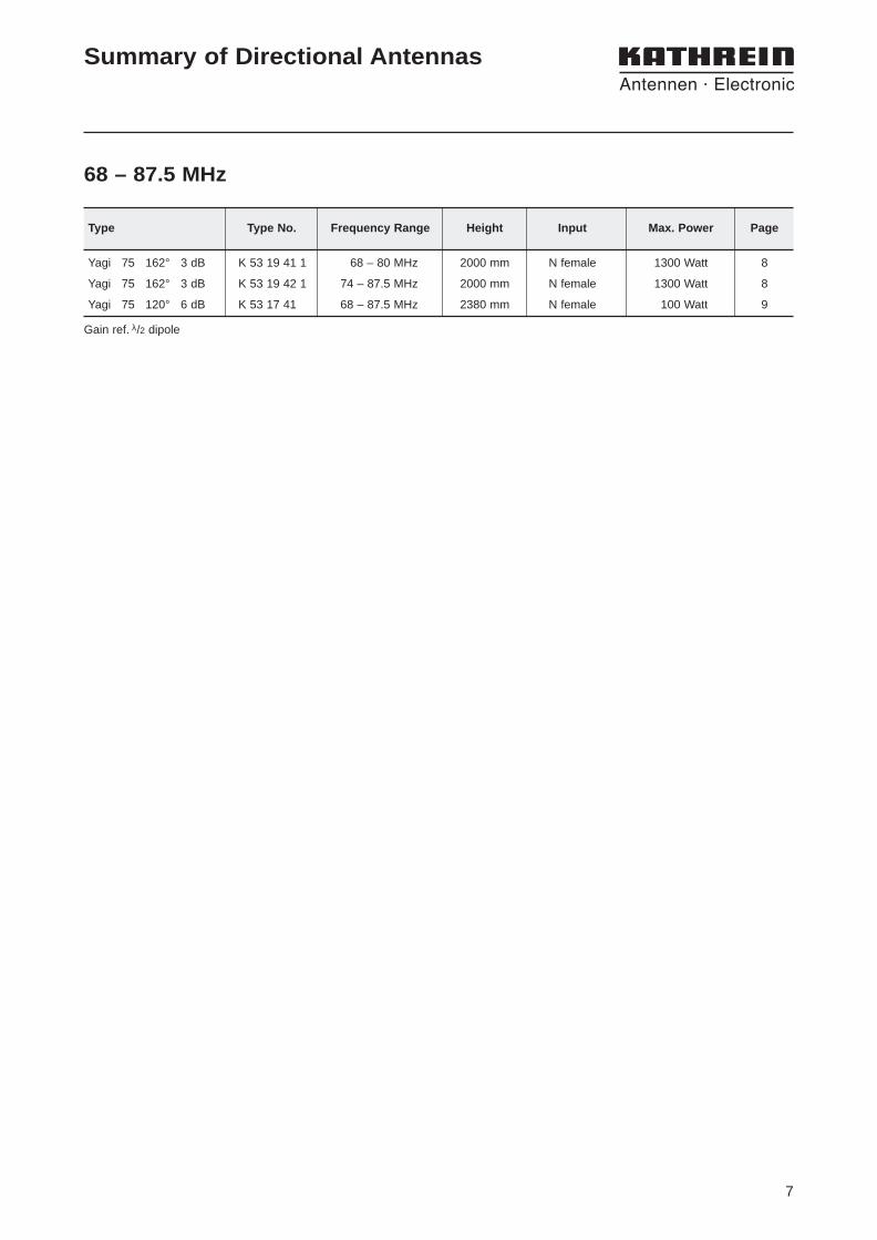
Yagi 75 162° 3 dB K 53 19 41 1 68 – 80 MHz 2000 mm N female 1300 Watt 8
Yagi 75 162° 3 dB K 53 19 42 1 74 – 87.5 MHz 2000 mm N female 1300 Watt 8
Yagi 75 120° 6 dB K 53 17 41 68 – 87.5 MHz 2380 mm N female 100 Watt 9
Type Type No. Frequency Range Height Input Max. Power Page
Summary of Directional Antennas
68 – 87.5 MHz
Gain ref. λ/2 dipole

8
Type No. K 53 19 41 1 K 53 19 42 1
Input N female N femaleFrequency range 68 – 80 MHz 74 – 87.5 MHzVSWR < 1.5Gain (ref. λ/2 dipole) 3 dBImpedance 50 ΩPolarization Suitable for horizontal or vertical polarization
by re-alignement of the attachement bracket.Max. power 1300 Watt (at 50 °C ambient temperature)Weight 12 kgWind load 260 N (at 150 km/h)Max. wind velocity 180 km/hPacking size 2154 x 798 x 132 mmHeight approx. 2000 mmDistance dipole / mast approx. 1200 mm
Directional Antenna
Broadband Yagi antennamade of hot-dip galvanized steel
Material: Hot-dip galvanized steel.All screws and nuts: Stainless steel.
Mounting: On masts from 60 – 115 mm diameter, clampssupplied.
Grounding: All metal parts of the antenna including themounting kit are DC grounded.The inner conductor is coupled capacitively.
Please note: The antenna is partly dismantled for easydispatch.
3 dB
10
0
77°
Radiation Patternin E-plane
3 dB
10
0
162°
Radiation Patternin H-plane
Yagi 75 162° 3dB
9
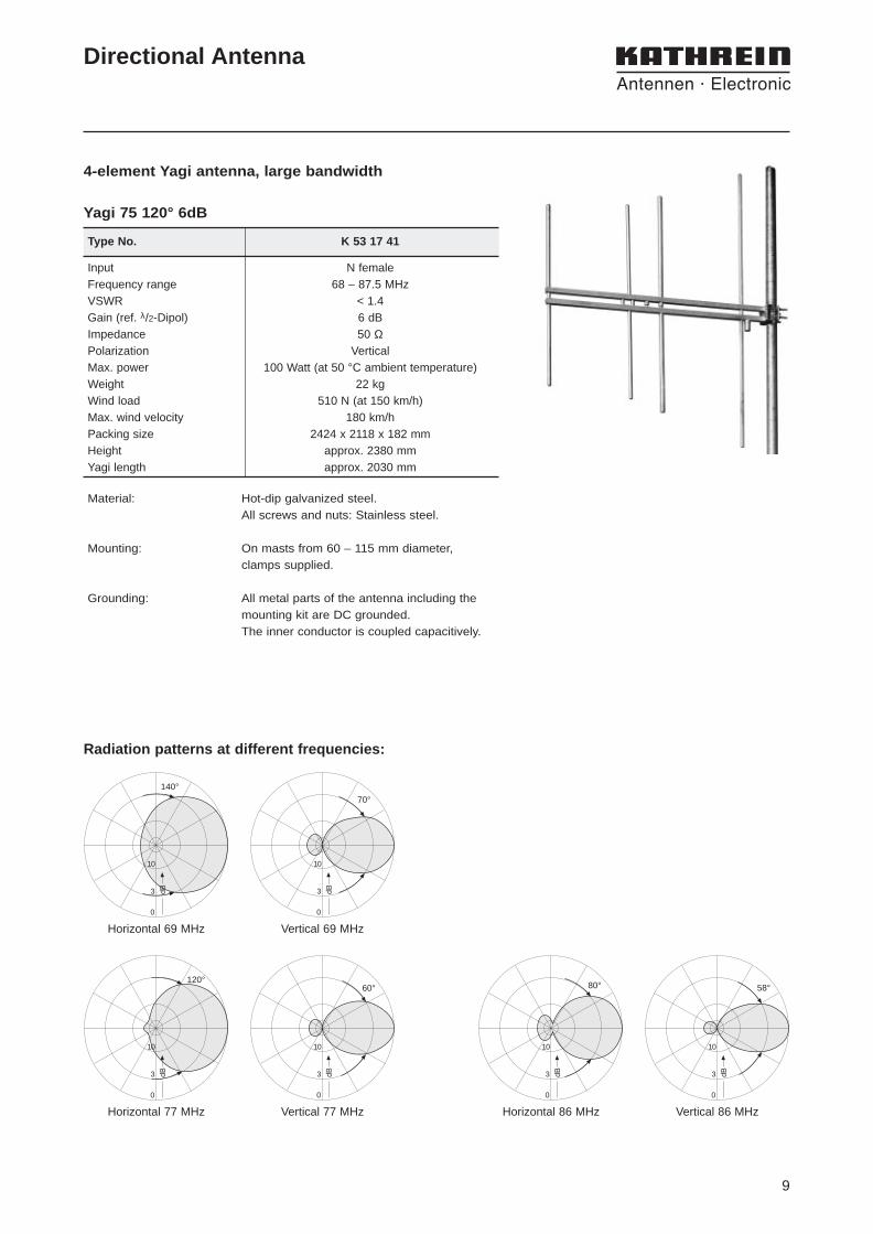
Type No. K 53 17 41
Input N femaleFrequency range 68 – 87.5 MHzVSWR < 1.4Gain (ref. λ/2-Dipol) 6 dBImpedance 50 ΩPolarization VerticalMax. power 100 Watt (at 50 °C ambient temperature)Weight 22 kgWind load 510 N (at 150 km/h)Max. wind velocity 180 km/hPacking size 2424 x 2118 x 182 mmHeight approx. 2380 mmYagi length approx. 2030 mm
Directional Antenna
4-element Yagi antenna, large bandwidth
Material: Hot-dip galvanized steel. All screws and nuts: Stainless steel.
Mounting: On masts from 60 – 115 mm diameter, clamps supplied.
Grounding: All metal parts of the antenna including themounting kit are DC grounded.The inner conductor is coupled capacitively.
3 dB
10
0
140°
Horizontal 69 MHz
3 dB
10
0
70°
Vertical 69 MHz
120°
3 dB
10
0
Horizontal 77 MHz
3 dB
10
0
60°
Vertical 77 MHz
3 dB
10
0
80°
Horizontal 86 MHz
3 dB
10
0
58°
Vertical 86 MHz
Radiation patterns at different frequencies:
Yagi 75 120° 6dB

10
11
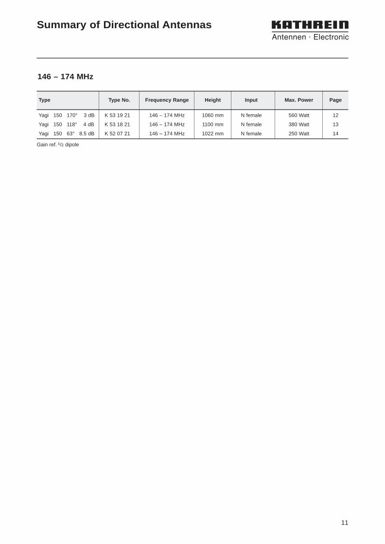
Summary of Directional Antennas
146 – 174 MHz
Yagi 150 170° 3 dB K 53 19 21 146 – 174 MHz 1060 mm N female 560 Watt 12
Yagi 150 118° 4 dB K 53 18 21 146 – 174 MHz 1100 mm N female 380 Watt 13
Yagi 150 63° 8.5 dB K 52 07 21 146 – 174 MHz 1022 mm N female 250 Watt 14
Type Type No. Frequency Range Height Input Max. Power Page
Gain ref. λ/2 dipole
12
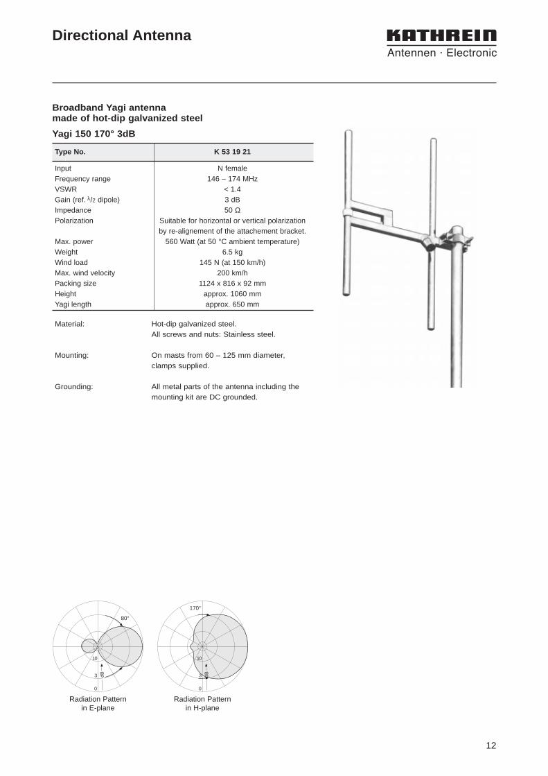
Type No. K 53 19 21
Input N femaleFrequency range 146 – 174 MHzVSWR < 1.4Gain (ref. λ/2 dipole) 3 dBImpedance 50 ΩPolarization Suitable for horizontal or vertical polarization
by re-alignement of the attachement bracket.Max. power 560 Watt (at 50 °C ambient temperature)Weight 6.5 kgWind load 145 N (at 150 km/h)Max. wind velocity 200 km/hPacking size 1124 x 816 x 92 mmHeight approx. 1060 mmYagi length approx. 650 mm
Directional Antenna
Broadband Yagi antennamade of hot-dip galvanized steel
Material: Hot-dip galvanized steel. All screws and nuts: Stainless steel.
Mounting: On masts from 60 – 125 mm diameter, clamps supplied.
Grounding: All metal parts of the antenna including themounting kit are DC grounded.
3 dB
10
0
80°
Radiation Patternin E-plane
3 dB
10
0
170°
Radiation Patternin H-plane
Yagi 150 170° 3dB
13
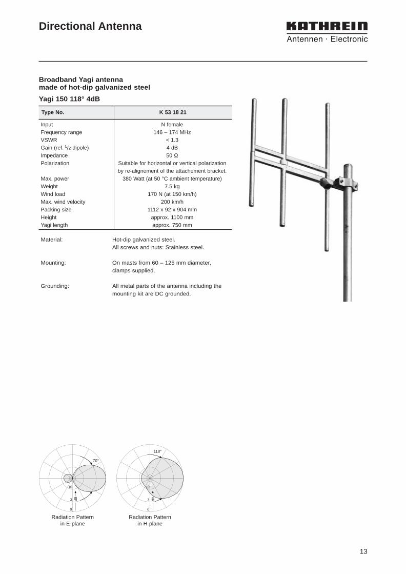
Type No. K 53 18 21
Input N femaleFrequency range 146 – 174 MHzVSWR < 1.3Gain (ref. λ/2 dipole) 4 dBImpedance 50 ΩPolarization Suitable for horizontal or vertical polarization
by re-alignement of the attachement bracket.Max. power 380 Watt (at 50 °C ambient temperature)Weight 7.5 kgWind load 170 N (at 150 km/h)Max. wind velocity 200 km/hPacking size 1112 x 92 x 904 mmHeight approx. 1100 mmYagi length approx. 750 mm
Directional Antenna
Broadband Yagi antennamade of hot-dip galvanized steel
Material: Hot-dip galvanized steel. All screws and nuts: Stainless steel.
Mounting: On masts from 60 – 125 mm diameter, clamps supplied.
Grounding: All metal parts of the antenna including themounting kit are DC grounded.
3 dB
10
0
70°
Radiation Patternin E-plane
3 dB
10
0
118°
Radiation Patternin H-plane
Yagi 150 118° 4dB
14
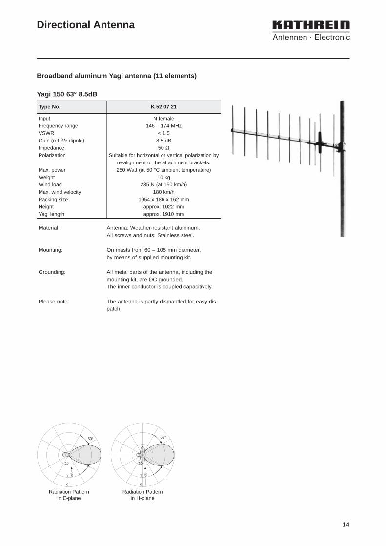
Type No. K 52 07 21
Input N femaleFrequency range 146 – 174 MHzVSWR < 1.5Gain (ref. λ/2 dipole) 8.5 dBImpedance 50 ΩPolarization Suitable for horizontal or vertical polarization by
re-alignment of the attachment brackets.Max. power 250 Watt (at 50 °C ambient temperature)Weight 10 kgWind load 235 N (at 150 km/h)Max. wind velocity 180 km/hPacking size 1954 x 186 x 162 mmHeight approx. 1022 mmYagi length approx. 1910 mm
Directional Antenna
Broadband aluminum Yagi antenna (11 elements)
Material: Antenna: Weather-resistant aluminum. All screws and nuts: Stainless steel.
Mounting: On masts from 60 – 105 mm diameter, by means of supplied mounting kit.
Grounding: All metal parts of the antenna, including themounting kit, are DC grounded.The inner conductor is coupled capacitively.
Please note: The antenna is partly dismantled for easy dis-patch.
3 dB
10
0
53°
Radiation Patternin E-plane
3 dB
10
0
63°
Radiation Patternin H-plane
Yagi 150 63° 8.5dB

15
Summary of Directional Antennas
Panel 420/450 63° 9 dBi K 73 36 21 406 – 512 MHz 493 mm N female 500 W 16
Panel 390/420 65° 11 dBi K 73 30 37 380 – 430 MHz 992 mm 7-16 female 500 W 17
Panel 420/450 67° 12 dBi K 73 30 21 400 – 512 MHz 992 mm N female 620 W 17
Panel 420/450 67° 12 dBi K 73 30 27 400 – 512 MHz 992 mm 7-16 female 840 W 17
Panel 390/420 65° 14 dBi K 73 33 37 380 – 430 MHz 1983 mm 7-16 female 500 W 18
Panel 420/450 68° 15 dBi K 73 33 21 400 – 512 MHz 1983 mm N female 620 W 18
Panel 420/450 68° 15 dBi K 73 33 27 400 – 512 MHz 1983 mm 7-16 female 1030 W 18
Panel 450 110° 13 dBi 738 049 440 – 470 MHz 2574 mm 7-16 female 500 W 19
Panel 390/420 115° 8.5 dBi 739 504 380 – 430 MHz 974 mm 7-16 female 500 W 20
Panel 390/420 115° 11.5 dBi 739 506 380 – 430 MHz 1934 mm 7-16 female 500 W 20
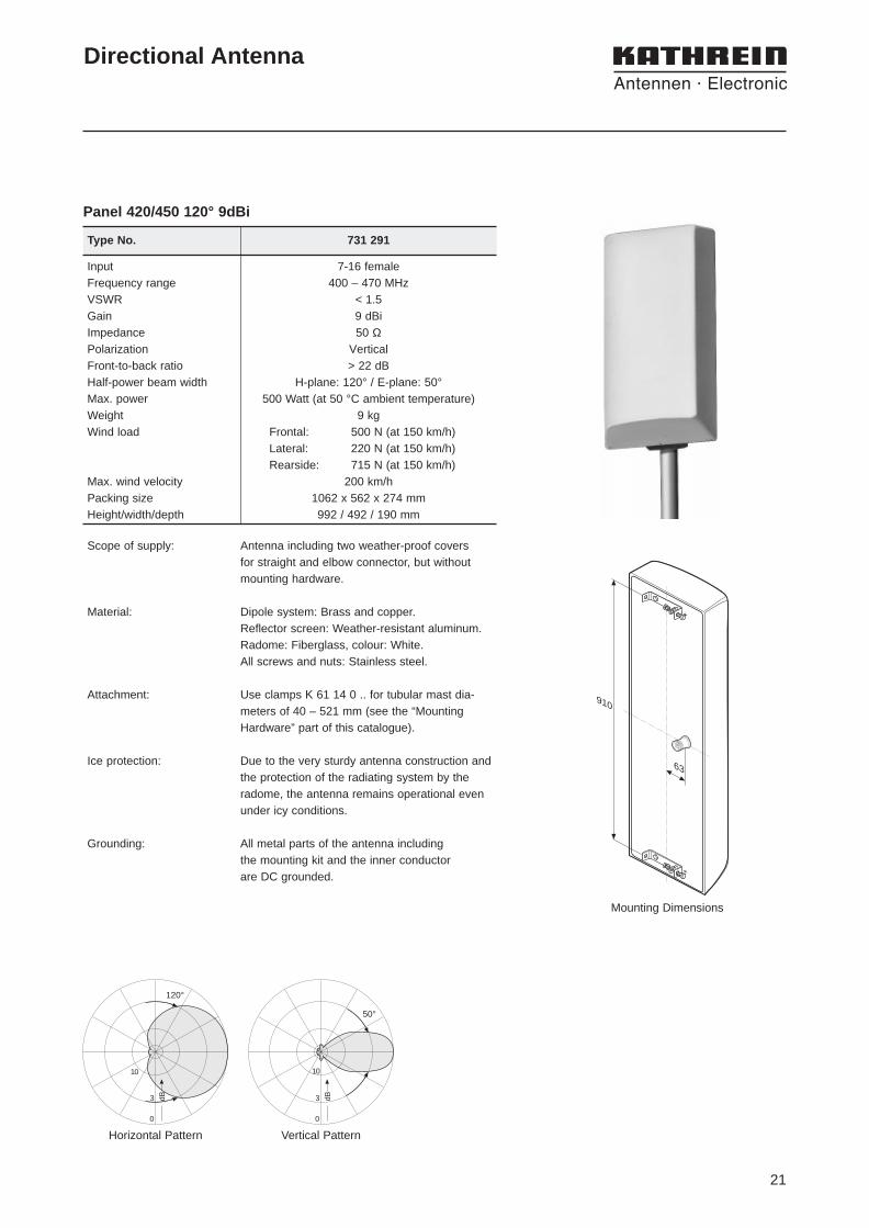
Panel 420/450 120° 9 dBi 731 291 400 – 470 MHz 992 mm 7-16 female 500 W 21
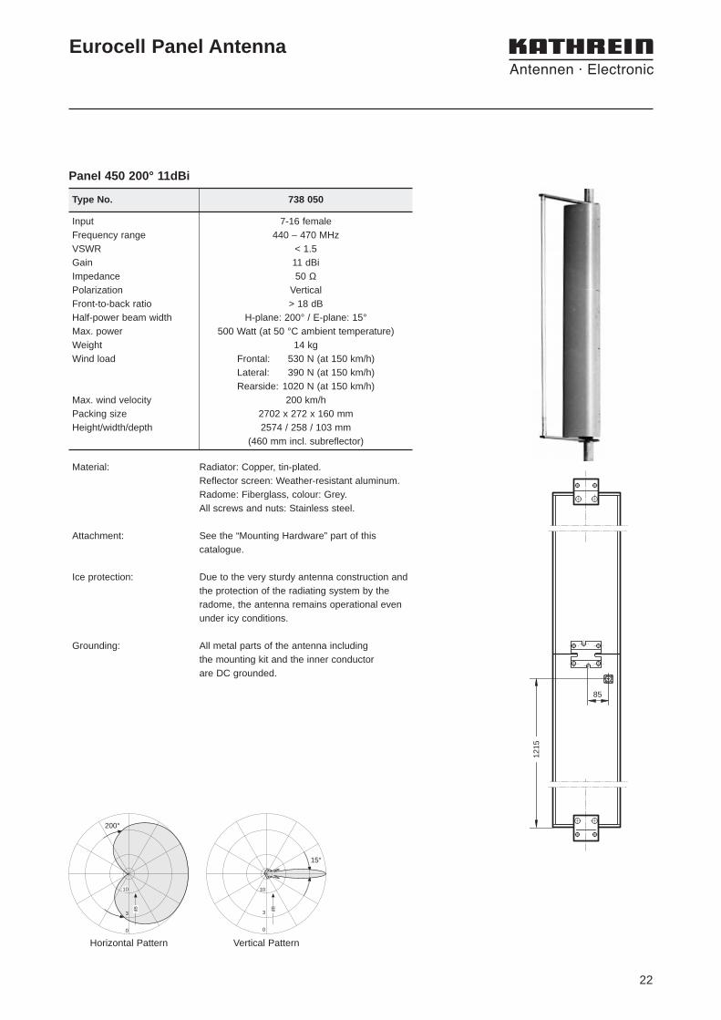
Panel 450 200° 11 dBi 738 050 440 – 470 MHz 2574 mm 7-16 female 500 W 22
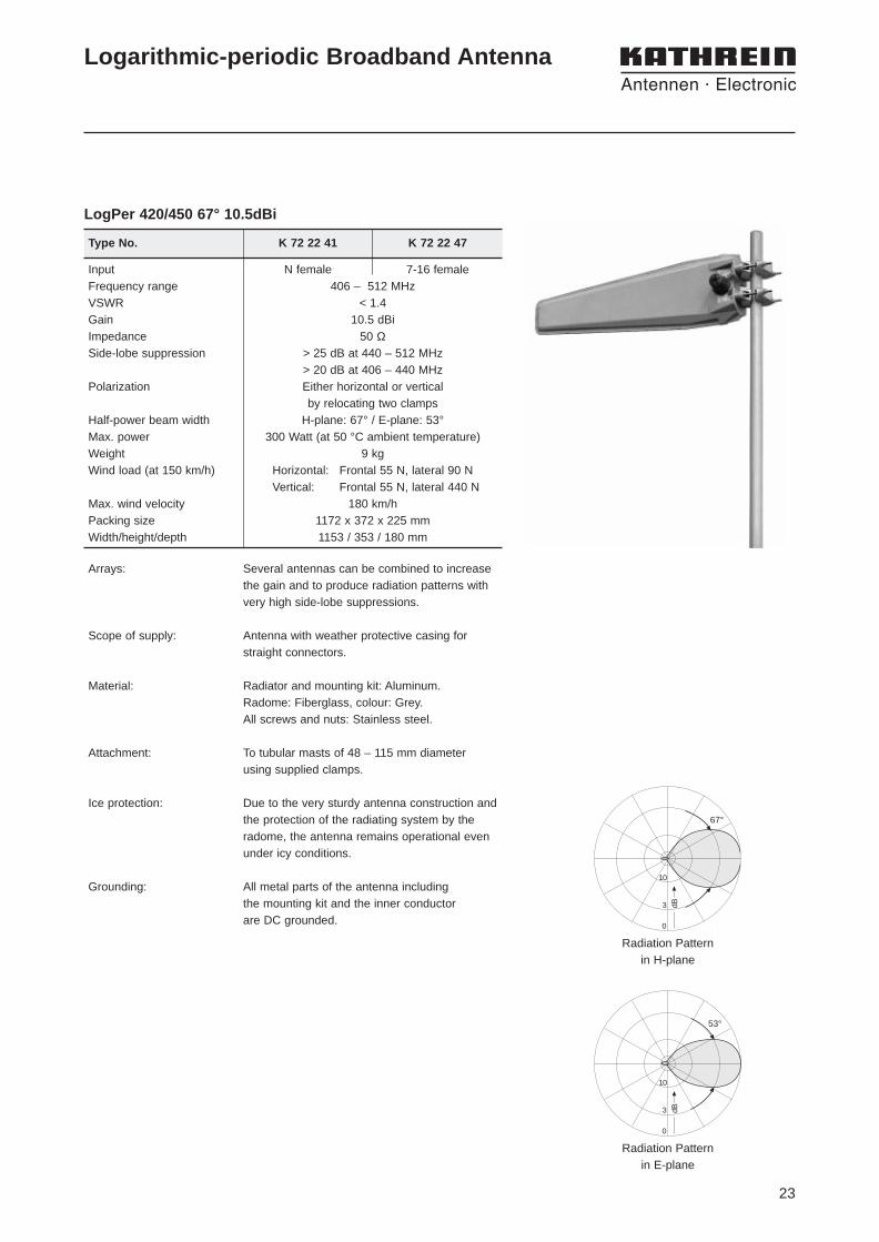
LogPer 420/450 67° 10.5 dBi K 72 22 41 406 – 512 MHz 353 mm N female 300 W 23
LogPer 420/450 67° 10.5 dBi K 72 22 47 406 – 512 MHz 353 mm 7-16 female 300 W 23
XPOL-Panel380-500 65° 12 dBi 741 515 380 – 500 MHz 992 mm 2 x 7-16 female 500 W 24380-500 65° 15 dBi 741 516 380 – 500 MHz 1983 mm 2 x 7-16 female 500 W 25380-430 68° 14.5 dBi 6°T 742 242 380 – 430 MHz 2000 mm 2 x 7-16 female 500 W 25
LogPer 450/900 68° 10.5 dBi 739 990 400 – 512 MHz 353 mm 7-16 female 100 W 2660° 11.5 dBi 824 – 960 MHz
LogPer 420/450 87° 9 dBi K 73 23 21 406 – 512 MHz 400 mm N female 500 W 27
Corner 390/420 44° 11 dBi K 73 12 21 360 – 490 MHz 500 mm N female 180 W 28/450
Helix 420/450 33° 12 dBi K 73 51 21 400 – 470 MHz 718 mm N female 500 W 29RHCP
360 – 512 MHz
Type Type No. Frequency Range Height InputMax.
PagePower
16
Directional Antenna
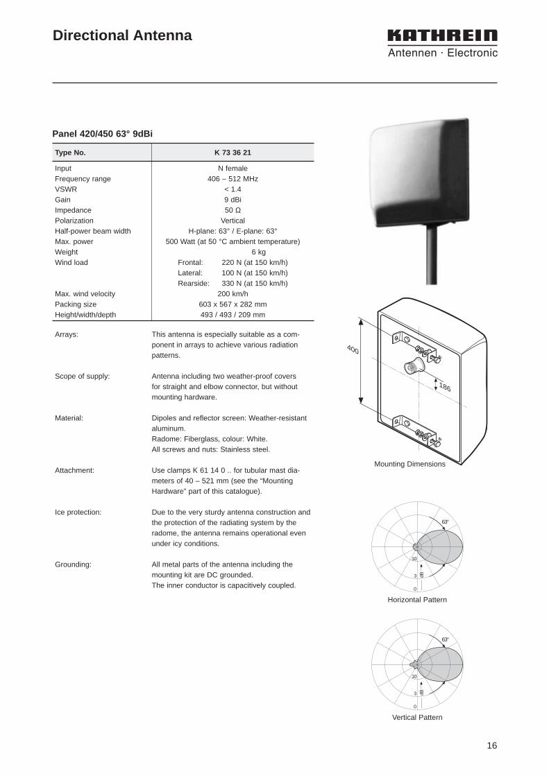
Panel 420/450 63° 9dBi
Horizontal Pattern
Vertical Pattern
3 dB
10
0
63°
3 dB
10
0
63°
400
186
Mounting Dimensions
Type No. K 73 36 21
Input N femaleFrequency range 406 – 512 MHzVSWR < 1.4Gain 9 dBiImpedance 50 ΩPolarization Vertical Half-power beam width H-plane: 63° / E-plane: 63°Max. power 500 Watt (at 50 °C ambient temperature)Weight 6 kgWind load Frontal: 220 N (at 150 km/h)
Lateral: 100 N (at 150 km/h)Rearside: 330 N (at 150 km/h)
Max. wind velocity 200 km/hPacking size 603 x 567 x 282 mmHeight/width/depth 493 / 493 / 209 mm
Arrays: This antenna is especially suitable as a com-ponent in arrays to achieve various radiationpatterns.
Scope of supply: Antenna including two weather-proof covers for straight and elbow connector, but withoutmounting hardware.
Material: Dipoles and reflector screen: Weather-resistantaluminum.Radome: Fiberglass, colour: White.All screws and nuts: Stainless steel.
Attachment: Use clamps K 61 14 0 .. for tubular mast dia-meters of 40 – 521 mm (see the “MountingHardware” part of this catalogue).
Ice protection: Due to the very sturdy antenna construction andthe protection of the radiating system by the radome, the antenna remains operational evenunder icy conditions.
Grounding: All metal parts of the antenna including themounting kit are DC grounded. The inner conductor is capacitively coupled.
17
Directional Antenna
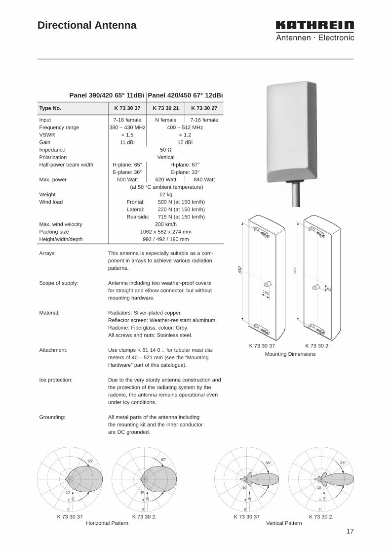
K 73 30 37 K 73 30 2.Horizontal Pattern
K 73 30 37 K 73 30 2.Vertical Pattern
K 73 30 37 K 73 30 2.
Mounting Dimensions
3 dB
10
0
33°
Panel 390/420 65° 11dBi Panel 420/450 67° 12dBi
3 dB
10
0
67°
3 dB
10
0
36°
3 dB
10
0
65°
Type No. K 73 30 37 K 73 30 21 K 73 30 27
Input 7-16 female N female 7-16 femaleFrequency range 380 – 430 MHz 400 – 512 MHzVSWR < 1.5 < 1.2Gain 11 dBi 12 dBiImpedance 50 ΩPolarization VerticalHalf-power beam width H-plane: 65° H-plane: 67°
E-plane: 36° E-plane: 33°Max. power 500 Watt 620 Watt 840 Watt
(at 50 °C ambient temperature)Weight 12 kgWind load Frontal: 500 N (at 150 km/h)
Lateral: 220 N (at 150 km/h)Rearside: 715 N (at 150 km/h)
Max. wind velocity 200 km/hPacking size 1062 x 562 x 274 mmHeight/width/depth 992 / 492 / 190 mm
850
12563
910
Arrays: This antenna is especially suitable as a com-ponent in arrays to achieve various radiationpatterns.
Scope of supply: Antenna including two weather-proof covers for straight and elbow connector, but withoutmounting hardware.
Material: Radiators: Silver-plated copper.Reflector screen: Weather-resistant aluminum.Radome: Fiberglass, colour: Grey.All screws and nuts: Stainless steel.
Attachment: Use clamps K 61 14 0 .. for tubular mast dia-meters of 40 – 521 mm (see the “MountingHardware” part of this catalogue).
Ice protection: Due to the very sturdy antenna construction andthe protection of the radiating system by theradome, the antenna remains operational evenunder icy conditions.
Grounding: All metal parts of the antenna including the mounting kit and the inner conductor are DC grounded.

18
3 dB
10
0
17°
Panel 390/420 65° 14dBi Panel 420/450 68° 15dBi
Type No. K 73 33 37 K 73 33 21 K 73 33 27
Input 7-16 female N female 7-16 femaleFrequency range 380 – 430 MHz 400 – 512 MHzVSWR < 1.5 < 1.2Gain 14 dBi 15 dBiImpedance 50 ΩPolarization VerticalHalf-power beam width H-plane: 65° H-plane: 68°
E-plane: 20° E-plane: 17°Max. power 500 Watt 620 Watt 1030 Watt
(at 50 °C ambient temperature)Weight 19 kgWind load Frontal: 1100 N (at 150 km/h)
Lateral: 440 N (at 150 km/h)Rearside: 1540 N (at 150 km/h)
Max. wind velocity 180 km/hPacking size 2062 x 562 x 274 mmHeight/width/depth 1983 / 485 / 190 mm
Directional Antenna
3 dB
10
0
68°
3 dB
10
0
19°
3 dB
10
0
65°
185095
1850
122
65
K 73 33 37 K 73 33 2.Horizontal Pattern
K 73 33 37 K 73 33 2.Vertical Pattern
K 73 33 37 K 73 33 2.
Mounting Dimensions
Arrays: This antenna is especially suitable as a com-ponent in arrays to achieve various radiationpatterns.
Scope of supply: Antenna including two weather-proof covers for straight and elbow connector, but withoutmounting hardware.
Material: Radiators: Silver-plated copper.Reflector screen: Weather-resistant aluminum.Radome: Fiberglass, colour: Grey.All screws and nuts: Stainless steel.
Attachment: Use clamps K 61 14 0 .. for tubular mast dia-meters of 40 – 521 mm (see the “MountingHardware” part of this catalogue).
Ice protection: Due to the very sturdy antenna construction andthe protection of the radiating system by theradome, the antenna remains operational evenunder icy conditions.
Grounding: All metal parts of the antenna including the mounting kit and the inner conductor are DC grounded.

19
3 dB
10
0
110°
Horizontal Pattern Vertical Pattern
738 049
10
3
0
15°
dB
Eurocell Panel Antenna
Panel 450 110° 13dBi
Type No. 738 049
Input 7-16 femaleFrequency range 440 – 470 MHzVSWR < 1.5Gain 13 dBiImpedance 50 ΩPolarization Vertical Front-to-back ratio > 18 dBHalf-power beam width H-plane: 110° / E-plane: 15°Max. power 500 Watt (at 50 °C ambient temperature)Weight 12 kgWind load Frontal: 460 N (at 150 km/h)
Lateral: 300 N (at 150 km/h)Rearside: 1020 N (at 150 km/h)
Max. wind velocity 200 km/hPacking size 2702 x 272 x 160 mmWidth/height/depth 2574 / 258 / 103 mm
85
1215
Vertical Pattern12° elektr. downtilt
737 439
3 dB
10
0
15°
Material: Radiator: Silver plated copper.Reflector screen: Weather-resistant aluminum.Radome: Fiberglass, colour: Grey.All screws and nuts: Stainless steel.
Attachment: See the “Mounting Hardware” part of thiscatalogue.
Ice protection: Due to the very sturdy antenna construction andthe protection of the radiating system by theradome, the antenna remains operational evenunder icy conditions.
Grounding: All metal parts of the antenna including the mounting kit and the inner conductor are DC grounded.
20
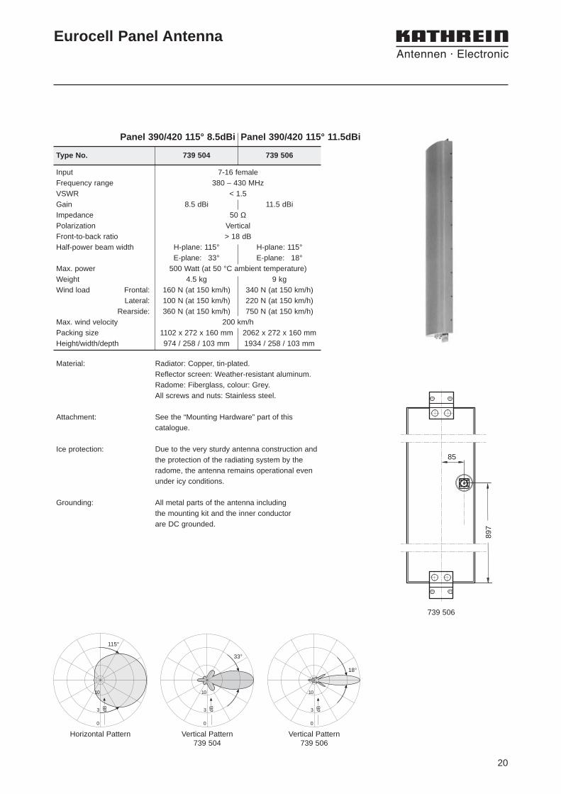
85
897
3 dB
10
0
33°
Vertical Pattern739 506
Horizontal Pattern
Eurocell Panel Antenna
Panel 390/420 115° 8.5dBi Panel 390/420 115° 11.5dBi
Type No. 739 504 739 506
Input 7-16 femaleFrequency range 380 – 430 MHzVSWR < 1.5Gain 8.5 dBi 11.5 dBiImpedance 50 ΩPolarization Vertical Front-to-back ratio > 18 dBHalf-power beam width H-plane: 115° H-plane: 115°
E-plane: 33° E-plane: 18°Max. power 500 Watt (at 50 °C ambient temperature)Weight 4.5 kg 9 kgWind load Frontal: 160 N (at 150 km/h) 340 N (at 150 km/h)
Lateral: 100 N (at 150 km/h) 220 N (at 150 km/h)Rearside: 360 N (at 150 km/h) 750 N (at 150 km/h)
Max. wind velocity 200 km/hPacking size 1102 x 272 x 160 mm 2062 x 272 x 160 mmHeight/width/depth 974 / 258 / 103 mm 1934 / 258 / 103 mm
739 506
3 dB
10
0
115°
3 dB
10
0
18°
Vertical Pattern739 504
Material: Radiator: Copper, tin-plated.Reflector screen: Weather-resistant aluminum.Radome: Fiberglass, colour: Grey.All screws and nuts: Stainless steel.
Attachment: See the “Mounting Hardware” part of thiscatalogue.
Ice protection: Due to the very sturdy antenna construction andthe protection of the radiating system by theradome, the antenna remains operational evenunder icy conditions.
Grounding: All metal parts of the antenna including the mounting kit and the inner conductor are DC grounded.
21
Vertical Pattern
3 dB
10
0
50°
910
63
Type No. 731 291
Input 7-16 femaleFrequency range 400 – 470 MHzVSWR < 1.5Gain 9 dBiImpedance 50 ΩPolarization VerticalFront-to-back ratio > 22 dB Half-power beam width H-plane: 120° / E-plane: 50°Max. power 500 Watt (at 50 °C ambient temperature)Weight 9 kgWind load Frontal: 500 N (at 150 km/h)
Lateral: 220 N (at 150 km/h)Rearside: 715 N (at 150 km/h)
Max. wind velocity 200 km/hPacking size 1062 x 562 x 274 mmHeight/width/depth 992 / 492 / 190 mm
Horizontal Pattern
3 dB
10
0
120°
Directional Antenna
Panel 420/450 120° 9dBi
Scope of supply: Antenna including two weather-proof covers for straight and elbow connector, but withoutmounting hardware.
Material: Dipole system: Brass and copper.Reflector screen: Weather-resistant aluminum.Radome: Fiberglass, colour: White.All screws and nuts: Stainless steel.
Attachment: Use clamps K 61 14 0 .. for tubular mast dia-meters of 40 – 521 mm (see the “MountingHardware” part of this catalogue).
Ice protection: Due to the very sturdy antenna construction andthe protection of the radiating system by the radome, the antenna remains operational evenunder icy conditions.
Grounding: All metal parts of the antenna including the mounting kit and the inner conductor are DC grounded.
Mounting Dimensions
22
Input 7-16 femaleFrequency range 440 – 470 MHzVSWR < 1.5Gain 11 dBiImpedance 50 ΩPolarization VerticalFront-to-back ratio > 18 dBHalf-power beam width H-plane: 200° / E-plane: 15°Max. power 500 Watt (at 50 °C ambient temperature)Weight 14 kgWind load Frontal: 530 N (at 150 km/h)
Lateral: 390 N (at 150 km/h)Rearside: 1020 N (at 150 km/h)
Max. wind velocity 200 km/hPacking size 2702 x 272 x 160 mmHeight/width/depth 2574 / 258 / 103 mm
(460 mm incl. subreflector)
Type No. 738 050
dB
10
3
0
200°
10
3
0
15°
dB
Eurocell Panel Antenna
Panel 450 200° 11dBi
85
1215
Vertical PatternHorizontal Pattern
Material: Radiator: Copper, tin-plated.Reflector screen: Weather-resistant aluminum.Radome: Fiberglass, colour: Grey.All screws and nuts: Stainless steel.
Attachment: See the “Mounting Hardware” part of thiscatalogue.
Ice protection: Due to the very sturdy antenna construction andthe protection of the radiating system by the radome, the antenna remains operational evenunder icy conditions.
Grounding: All metal parts of the antenna including the mounting kit and the inner conductor are DC grounded.
23
Type No. K 72 22 41 K 72 22 47
Radiation Patternin H-plane
3 dB
10
0
67°
Radiation Patternin E-plane
3 dB
10
0
53°
Logarithmic-periodic Broadband Antenna
LogPer 420/450 67° 10.5dBi
Arrays: Several antennas can be combined to increasethe gain and to produce radiation patterns withvery high side-lobe suppressions.
Scope of supply: Antenna with weather protective casing forstraight connectors.
Material: Radiator and mounting kit: Aluminum.Radome: Fiberglass, colour: Grey.All screws and nuts: Stainless steel.
Attachment: To tubular masts of 48 – 115 mm diameter using supplied clamps.
Ice protection: Due to the very sturdy antenna construction andthe protection of the radiating system by theradome, the antenna remains operational evenunder icy conditions.
Grounding: All metal parts of the antenna including the mounting kit and the inner conductor are DC grounded.
Input N female 7-16 femaleFrequency range 406 – 512 MHzVSWR < 1.4Gain 10.5 dBiImpedance 50 ΩSide-lobe suppression > 25 dB at 440 – 512 MHz
> 20 dB at 406 – 440 MHzPolarization Either horizontal or vertical
by relocating two clampsHalf-power beam width H-plane: 67° / E-plane: 53°Max. power 300 Watt (at 50 °C ambient temperature)Weight 9 kgWind load (at 150 km/h) Horizontal: Frontal 55 N, lateral 90 N
Vertical: Frontal 55 N, lateral 440 NMax. wind velocity 180 km/hPacking size 1172 x 372 x 225 mmWidth/height/depth 1153 / 353 / 180 mm
24
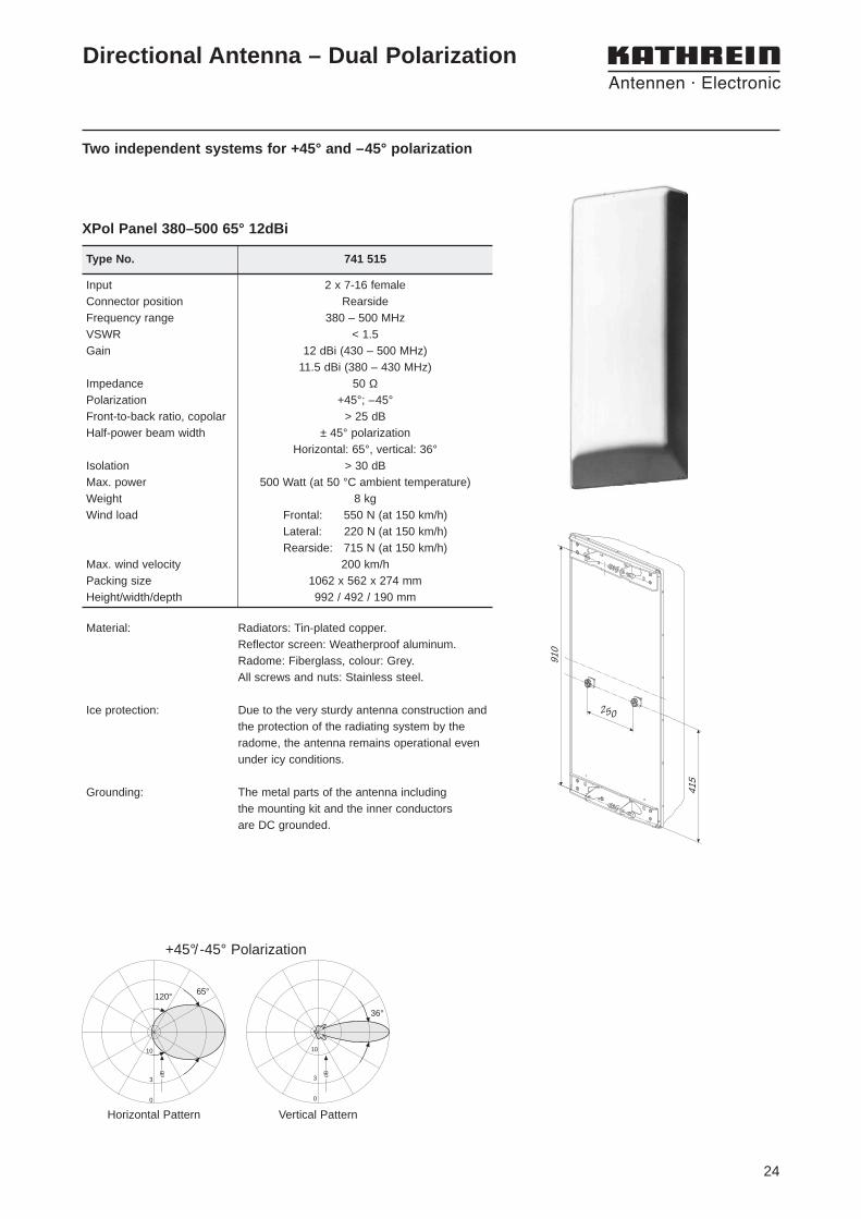
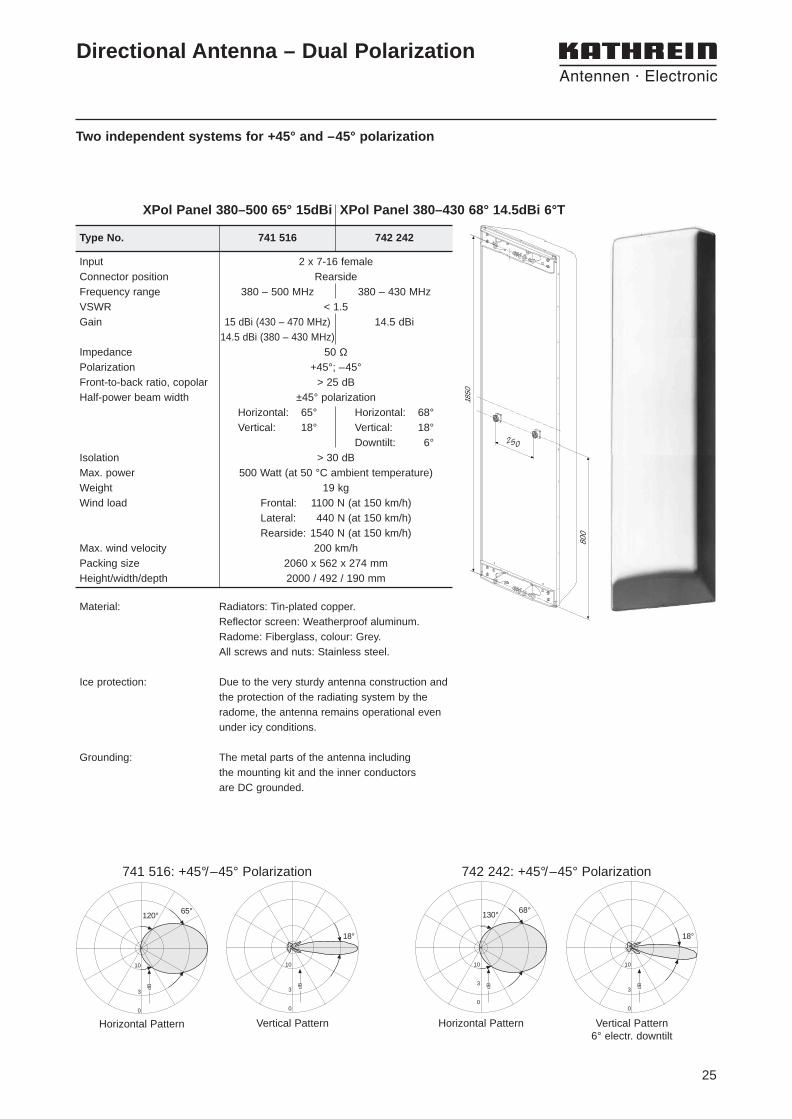
Two independent systems for +45° and –45° polarization
Horizontal Pattern Vertical Pattern
65°120°
dB
10
3
0
3
0
10
dB
36°
+45°/ -45° Polarization
Directional Antenna – Dual Polarization
Type No. 741 515
Input 2 x 7-16 femaleConnector position RearsideFrequency range 380 – 500 MHzVSWR < 1.5Gain 12 dBi (430 – 500 MHz)
11.5 dBi (380 – 430 MHz)Impedance 50 ΩPolarization +45°; –45°Front-to-back ratio, copolar > 25 dBHalf-power beam width ± 45° polarization
Horizontal: 65°, vertical: 36°Isolation > 30 dBMax. power 500 Watt (at 50 °C ambient temperature)Weight 8 kgWind load Frontal: 550 N (at 150 km/h)
Lateral: 220 N (at 150 km/h)Rearside: 715 N (at 150 km/h)
Max. wind velocity 200 km/hPacking size 1062 x 562 x 274 mmHeight/width/depth 992 / 492 / 190 mm
XPol Panel 380–500 65° 12dBi
Material: Radiators: Tin-plated copper.Reflector screen: Weatherproof aluminum.Radome: Fiberglass, colour: Grey.All screws and nuts: Stainless steel.
Ice protection: Due to the very sturdy antenna construction andthe protection of the radiating system by theradome, the antenna remains operational evenunder icy conditions.
Grounding: The metal parts of the antenna including the mounting kit and the inner conductors are DC grounded.
250
415
910
25
Two independent systems for +45° and –45° polarization
Horizontal Pattern Vertical Pattern
65°120°
dB
10
3
0
10
3
0
18°
dB
Directional Antenna – Dual Polarization
Type No. 741 516 742 242
Input 2 x 7-16 femaleConnector position RearsideFrequency range 380 – 500 MHz 380 – 430 MHzVSWR < 1.5Gain 15 dBi (430 – 470 MHz) 14.5 dBi
14.5 dBi (380 – 430 MHz)Impedance 50 ΩPolarization +45°; –45°Front-to-back ratio, copolar > 25 dBHalf-power beam width ±45° polarization
Horizontal: 65° Horizontal: 68°Vertical: 18° Vertical: 18°
Downtilt: 6°Isolation > 30 dBMax. power 500 Watt (at 50 °C ambient temperature)Weight 19 kgWind load Frontal: 1100 N (at 150 km/h)
Lateral: 440 N (at 150 km/h)Rearside: 1540 N (at 150 km/h)
Max. wind velocity 200 km/hPacking size 2060 x 562 x 274 mmHeight/width/depth 2000 / 492 / 190 mm
Material: Radiators: Tin-plated copper.Reflector screen: Weatherproof aluminum.Radome: Fiberglass, colour: Grey.All screws and nuts: Stainless steel.
Ice protection: Due to the very sturdy antenna construction andthe protection of the radiating system by theradome, the antenna remains operational evenunder icy conditions.
Grounding: The metal parts of the antenna including the mounting kit and the inner conductors are DC grounded.
250
800
1850
Horizontal Pattern Vertical Pattern6° electr. downtilt
10
3
0
68°130°
dB
10
3
0
18°
dB
742 242: +45°/–45° Polarization741 516: +45°/–45° Polarization
XPol Panel 380–500 65° 15dBi XPol Panel 380–430 68° 14.5dBi 6°T
26
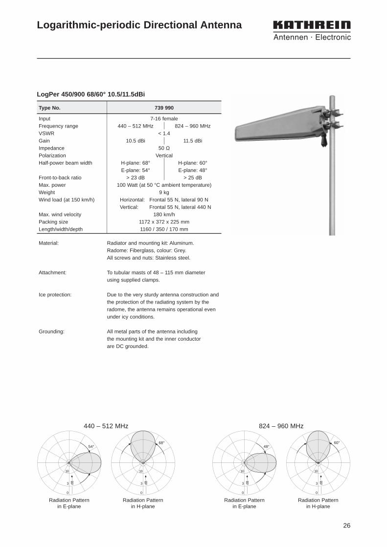
Logarithmic-periodic Directional Antenna
Input 7-16 femaleFrequency range 440 – 512 MHz 824 – 960 MHzVSWR < 1.4Gain 10.5 dBi 11.5 dBiImpedance 50 ΩPolarization VerticalHalf-power beam width H-plane: 68° H-plane: 60°
E-plane: 54° E-plane: 48°Front-to-back ratio > 23 dB > 25 dBMax. power 100 Watt (at 50 °C ambient temperature)Weight 9 kgWind load (at 150 km/h) Horizontal: Frontal 55 N, lateral 90 N
Vertical: Frontal 55 N, lateral 440 NMax. wind velocity 180 km/hPacking size 1172 x 372 x 225 mmLength/width/depth 1160 / 350 / 170 mm
Type No. 739 990
LogPer 450/900 68/60° 10.5/11.5dBi
Material: Radiator and mounting kit: Aluminum.Radome: Fiberglass, colour: Grey.All screws and nuts: Stainless steel.
Attachment: To tubular masts of 48 – 115 mm diameter using supplied clamps.
Ice protection: Due to the very sturdy antenna construction andthe protection of the radiating system by theradome, the antenna remains operational evenunder icy conditions.
Grounding: All metal parts of the antenna including the mounting kit and the inner conductor are DC grounded.
Radiation Patternin E-plane
Radiation Patternin H-plane
54°
3 dB
10
0
68°
3 dB
10
0
440 – 512 MHz
Radiation Patternin E-plane
Radiation Patternin H-plane
48°
3 dB
10
0
60°
3 dB
10
0
824 – 960 MHz

27
Logarithmic-periodic Broadband Antenna
Scope of supply: Antenna with weather protective casing forstraight connectors.
Material: Radiator: Weather-resistant aluminum.Radome: Fiberglass, colour: White.Mounting kit: Hot-dip galvanized steel.All screws and nuts: Stainless steel.
Attachment: To tubular masts of 60 – 115 mm diameter using supplied clamps.
Ice protection: Due to the very sturdy antenna construction andthe protection of the radiating system by theradome, the antenna remains operational evenunder icy conditions.
Grounding: All metal parts of the antenna including the mounting kit and the inner conductor are DC grounded.
400f / MHz
20
24
Typische Nebenkeulendämpfung
450 550500
dB
28
Vertical Pattern
Horizontal Pattern
3 dB
10
0
62°
3 dB
10
0
87°
• Very small wind load
Type No. K 73 23 21
LogPer 450 87° 9dBi
Input N femaleFrequency range 406 – 512 MHzVSWR < 1.3Gain 9 dBiImpedance 50 ΩSide-lobe suppression > 28 dB at 440 – 512 MHz
> 21 dB at 406 – 512 MHzPolarization VerticalHalf-power beam width H-plane: 87° / E-plane: 62°Max. power 500 Watt (at 50 °C ambient temperature)Weight 8.3 kgWind load Frontal: 54 N (at 150 km/h)
Lateral: 150 N (at 150 km/h)Rearside: 80 N (at 150 km/h)
Max. wind velocity 180 km/hPacking size 914 x 482 x 482 mmWidth/height/depth 860 / 400 / 400 mm
Typical side-lobe suppression
28
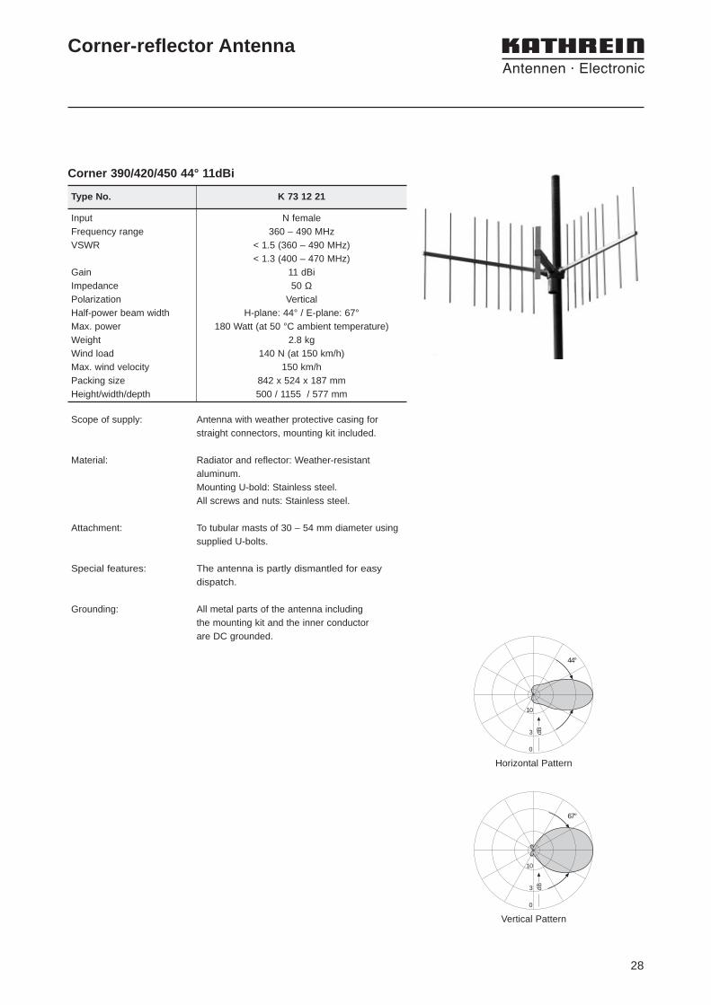
Corner 390/420/450 44° 11dBi
Corner-reflector Antenna
Scope of supply: Antenna with weather protective casing forstraight connectors, mounting kit included.
Material: Radiator and reflector: Weather-resistantaluminum. Mounting U-bold: Stainless steel.All screws and nuts: Stainless steel.
Attachment: To tubular masts of 30 – 54 mm diameter usingsupplied U-bolts.
Special features: The antenna is partly dismantled for easydispatch.
Grounding: All metal parts of the antenna including the mounting kit and the inner conductor are DC grounded.
Horizontal Pattern
Vertical Pattern
3 dB
10
0
67°
3 dB
10
0
44°
Type No. K 73 12 21
Input N femaleFrequency range 360 – 490 MHzVSWR < 1.5 (360 – 490 MHz)
< 1.3 (400 – 470 MHz)Gain 11 dBiImpedance 50 ΩPolarization VerticalHalf-power beam width H-plane: 44° / E-plane: 67°Max. power 180 Watt (at 50 °C ambient temperature)Weight 2.8 kgWind load 140 N (at 150 km/h)Max. wind velocity 150 km/hPacking size 842 x 524 x 187 mmHeight/width/depth 500 / 1155 / 577 mm

29
Type No. K 73 51 21
Helix Antenna
Scope of supply: Antenna with weather protective casing forstraight connectors, mounting kit included.
Material: Antenna: Copper band helix in protective fiber-glass tube, colour: Grey.Reflector screen: Weather-resistant aluminum.Attachment construction: Hot dip galvanizedsteel.All screws and nuts: Stainless steel.
Attachment: To tubular masts of 60 – 125 mm diameter usingsupplied U-bolts.
Grounding: All metal parts of the antenna including the mounting kit and the inner conductor are DC grounded.
Please note: The reflector screen is made of two parts andcan be removed for transport.
Relative field strength in mid-band
Mounting Instructions
3 dB
10
0
33°
Input N femaleFrequency range 400 – 470 MHzPolarization right handed circular (RHCP)VSWR < 1.2Gain 12 dB
(ref. to the circularly polarized isotropic antenna)Impedance 50 ΩMax. power 560 Watt (at 50 °C ambient temperature)Weight 12 kgWind load 450 N (at 150 km/h)Max. wind velocity 200 km/hPacking size 1684 x 388 x 277 mmReflector diameter 718 mmLength / tube diameter 1540 / 204 mm
• Circular polarization
Helix 420/450 33° 12dBi

30
31
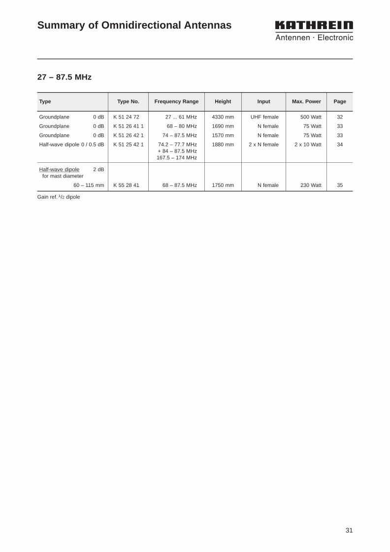
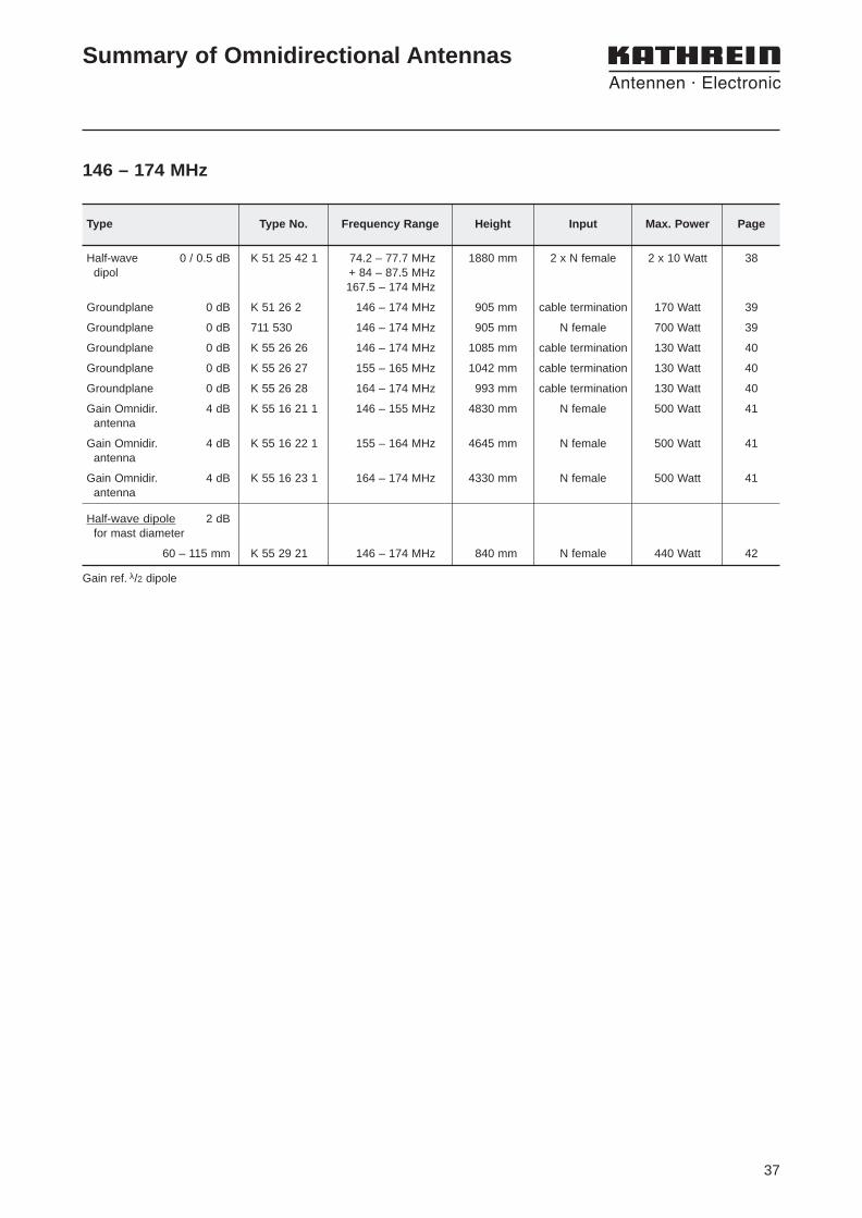
Summary of Omnidirectional Antennas
27 – 87.5 MHz
Groundplane 0 dB K 51 24 72 27 ... 61 MHz 4330 mm UHF female 500 Watt 32
Groundplane 0 dB K 51 26 41 1 68 – 80 MHz 1690 mm N female 75 Watt 33
Groundplane 0 dB K 51 26 42 1 74 – 87.5 MHz 1570 mm N female 75 Watt 33
Half-wave dipole 0 / 0.5 dB K 51 25 42 1 74.2 – 77.7 MHz 1880 mm 2 x N female 2 x 10 Watt 34+ 84 – 87.5 MHz167.5 – 174 MHz
Half-wave dipole 2 dBfor mast diameter
60 – 115 mm K 55 28 41 68 – 87.5 MHz 1750 mm N female 230 Watt 35
Type Type No. Frequency Range Height Input Max. Power Page
Gain ref. λ/2 dipole
32
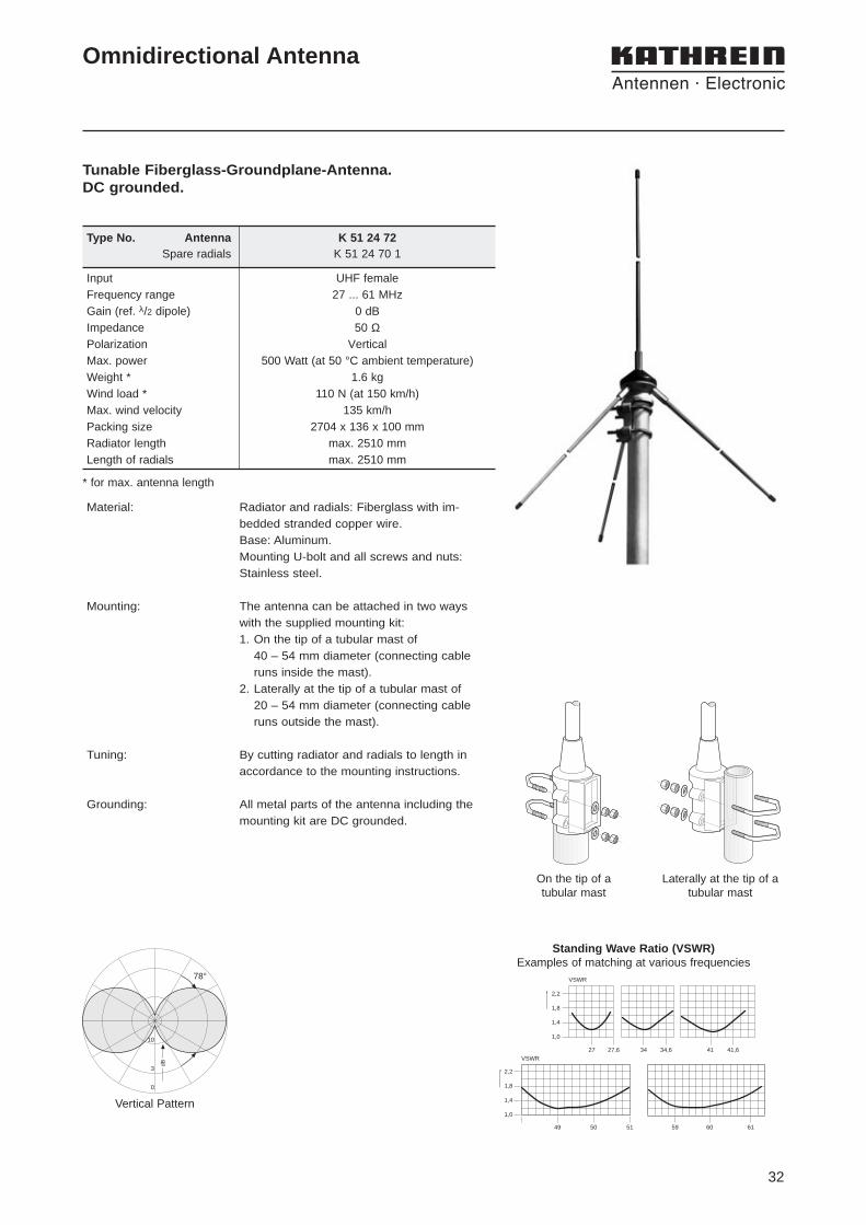
Type No. Antenna K 51 24 72Spare radials K 51 24 70 1
Input UHF femaleFrequency range 27 ... 61 MHzGain (ref. λ/2 dipole) 0 dBImpedance 50 ΩPolarization VerticalMax. power 500 Watt (at 50 °C ambient temperature)Weight * 1.6 kgWind load * 110 N (at 150 km/h)Max. wind velocity 135 km/hPacking size 2704 x 136 x 100 mmRadiator length max. 2510 mmLength of radials max. 2510 mm
Tunable Fiberglass-Groundplane-Antenna.DC grounded.
Omnidirectional Antenna
Material: Radiator and radials: Fiberglass with im-bedded stranded copper wire.Base: Aluminum.Mounting U-bolt and all screws and nuts: Stainless steel.
Mounting: The antenna can be attached in two ways with the supplied mounting kit:1. On the tip of a tubular mast of
40 – 54 mm diameter (connecting cable runs inside the mast).
2. Laterally at the tip of a tubular mast of 20 – 54 mm diameter (connecting cable runs outside the mast).
Tuning: By cutting radiator and radials to length inaccordance to the mounting instructions.
Grounding: All metal parts of the antenna including themounting kit are DC grounded.
Vertical Pattern
On the tip of atubular mast
Laterally at the tip of atubular mast
dB
78°
10
3
0
Standing Wave Ratio (VSWR)Examples of matching at various frequencies
2,2
1,8
1,4
1,0
49 50 51 59 60 61
VSWR
2,2
1,8
1,4
1,0
27 27,6 34 34,6 41 41,6
VSWR
* for max. antenna length

33
10
3
0
dB dB
78°
10
3
0
Horizontal Pattern On the tip of a tubular mast
Laterally at the tip of atubular mast
Vertical Pattern
Broadband groundplane antenna with fiberglass radials.
Omnidirectional Antenna
Type No. Antenna K 51 26 41 1 K 51 26 42 1Spare radials K 51 26 40 12 K 51 26 40 22
Input N femaleFrequency range 68 – 80 MHz 74 – 87.5 MHzVSWR < 1.5Gain (ref. λ/2 dipole) 0 dBImpedance 50 ΩPolarization VerticalMax. power 75 Watt (at 50 °C ambient temperature)Weight 1.8 kg 1.6 kgWind load 70 N 65 N
(at 150 km/h)Max. wind velocity 200 km/hPacking size 1114 x 132 x 112 mmRadiator length 747 mm 680 mmLength of radials 1053 mm 970 mm
Material: Radiator: Stainless steel.Radials: Fiberglass with imbedded strandedcopper wire.Base: Aluminum.Mounting U-bolt and all screws and nuts:Stainless steel.
Mounting: The antenna can be attached in two ways with the supplied mounting kit:1. On the tip of a tubular mast of
40 – 54 mm diameter (connecting cableruns inside the mast).
2. Laterally at the tip of a tubular mast of 20 – 40 mm diameter (connecting cableruns outside the mast).
Side mounting at a mast: See catalogue part “Technical Supplement”.
Grounding: All metal parts of the antenna including themounting kit are DC grounded.
34
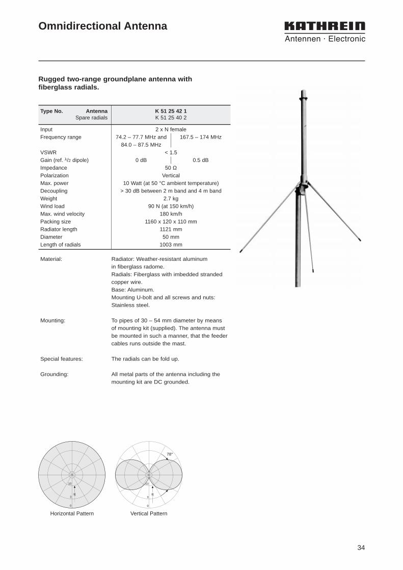
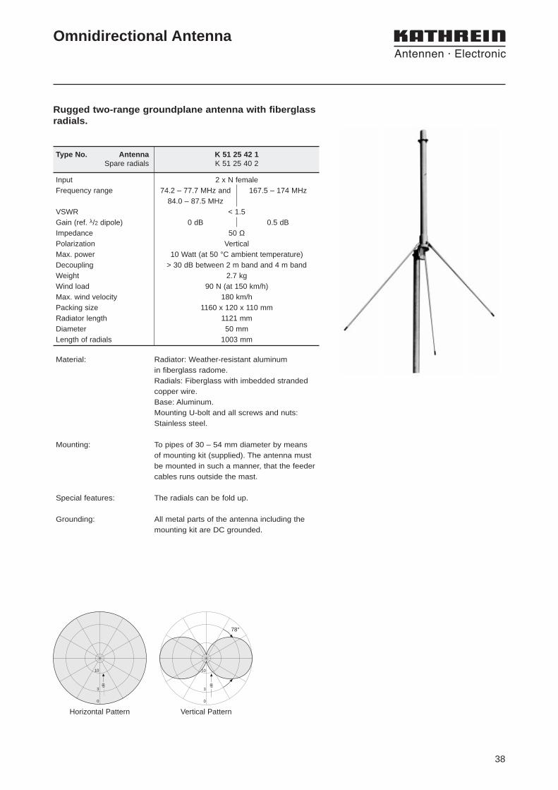
Rugged two-range groundplane antenna with fiberglass radials.
Omnidirectional Antenna
10
3
0
dB dB
78°
10
3
0
Horizontal Pattern Vertical Pattern
Type No. Antenna K 51 25 42 1Spare radials K 51 25 40 2
Input 2 x N femaleFrequency range 74.2 – 77.7 MHz and 167.5 – 174 MHz
84.0 – 87.5 MHzVSWR < 1.5Gain (ref. λ/2 dipole) 0 dB 0.5 dBImpedance 50 ΩPolarization VerticalMax. power 10 Watt (at 50 °C ambient temperature)Decoupling > 30 dB between 2 m band and 4 m bandWeight 2.7 kgWind load 90 N (at 150 km/h)Max. wind velocity 180 km/hPacking size 1160 x 120 x 110 mmRadiator length 1121 mmDiameter 50 mmLength of radials 1003 mm
Material: Radiator: Weather-resistant aluminum in fiberglass radome.Radials: Fiberglass with imbedded strandedcopper wire.Base: Aluminum. Mounting U-bolt and all screws and nuts:Stainless steel.
Mounting: To pipes of 30 – 54 mm diameter by means of mounting kit (supplied). The antenna mustbe mounted in such a manner, that the feedercables runs outside the mast.
Special features: The radials can be fold up.
Grounding: All metal parts of the antenna including themounting kit are DC grounded.
35
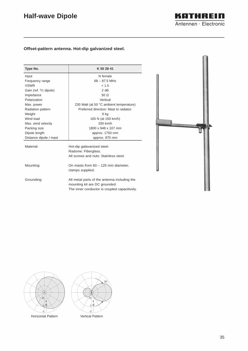
Half-wave Dipole
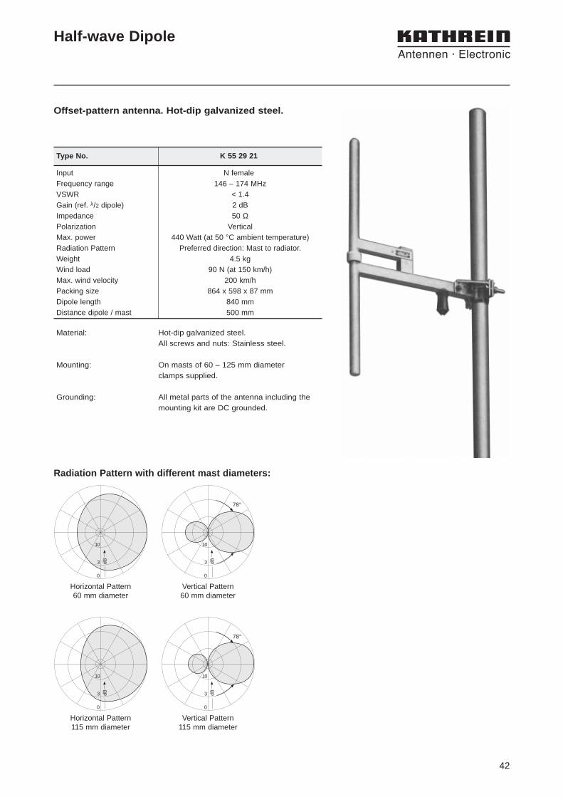
Offset-pattern antenna. Hot-dip galvanized steel.
3 dB
10
0
3 dB
10
0
78°
Horizontal Pattern Vertical Pattern
Type No. K 55 28 41
Input N femaleFrequency range 68 – 87.5 MHzVSWR < 1.5Gain (ref. λ/2 dipole) 2 dBImpedance 50 ΩPolarization VerticalMax. power 230 Watt (at 50 °C ambient temperature)Radiation pattern Preferred direction: Mast to radiator.Weight 9 kgWind load 165 N (at 150 km/h)Max. wind velocity 200 km/hPacking size 1800 x 948 x 107 mmDipole length approx. 1750 mmDistance dipole / mast approx. 870 mm
Material: Hot-dip galavanized steel.Radome: Fiberglass.All screws and nuts: Stainless steel.
Mounting: On masts from 60 – 125 mm diameter,clamps supplied.
Grounding: All metal parts of the antenna including themounting kit are DC grounded.The inner conductor is coupled capacitively.

36
37
Half-wave 0 / 0.5 dB K 51 25 42 1 74.2 – 77.7 MHz 1880 mm 2 x N female 2 x 10 Watt 38dipol + 84 – 87.5 MHz
167.5 – 174 MHz
Groundplane 0 dB K 51 26 2 146 – 174 MHz 905 mm cable termination 170 Watt 39
Groundplane 0 dB 711 530 146 – 174 MHz 905 mm N female 700 Watt 39
Groundplane 0 dB K 55 26 26 146 – 174 MHz 1085 mm cable termination 130 Watt 40
Groundplane 0 dB K 55 26 27 155 – 165 MHz 1042 mm cable termination 130 Watt 40
Groundplane 0 dB K 55 26 28 164 – 174 MHz 993 mm cable termination 130 Watt 40
Gain Omnidir. 4 dB K 55 16 21 1 146 – 155 MHz 4830 mm N female 500 Watt 41antenna
Gain Omnidir. 4 dB K 55 16 22 1 155 – 164 MHz 4645 mm N female 500 Watt 41antenna
Gain Omnidir. 4 dB K 55 16 23 1 164 – 174 MHz 4330 mm N female 500 Watt 41antenna
Half-wave dipole 2 dBfor mast diameter
60 – 115 mm K 55 29 21 146 – 174 MHz 840 mm N female 440 Watt 42
Summary of Omnidirectional Antennas
146 – 174 MHz
Type Type No. Frequency Range Height Input Max. Power Page
Gain ref. λ/2 dipole
38
10
3
0
dB dB
78°
10
3
0
Horizontal Pattern Vertical Pattern
Rugged two-range groundplane antenna with fiberglassradials.
Omnidirectional Antenna
Type No. Antenna K 51 25 42 1Spare radials K 51 25 40 2
Input 2 x N femaleFrequency range 74.2 – 77.7 MHz and 167.5 – 174 MHz
84.0 – 87.5 MHzVSWR < 1.5Gain (ref. λ/2 dipole) 0 dB 0.5 dBImpedance 50 ΩPolarization VerticalMax. power 10 Watt (at 50 °C ambient temperature)Decoupling > 30 dB between 2 m band and 4 m bandWeight 2.7 kgWind load 90 N (at 150 km/h)Max. wind velocity 180 km/hPacking size 1160 x 120 x 110 mmRadiator length 1121 mmDiameter 50 mmLength of radials 1003 mm
Material: Radiator: Weather-resistant aluminum in fiberglass radome.Radials: Fiberglass with imbedded strandedcopper wire.Base: Aluminum. Mounting U-bolt and all screws and nuts:Stainless steel.
Mounting: To pipes of 30 – 54 mm diameter by means of mounting kit (supplied). The antenna mustbe mounted in such a manner, that the feedercables runs outside the mast.
Special features: The radials can be fold up.
Grounding: All metal parts of the antenna including themounting kit are DC grounded.
39
10
3
0
dB dB
78°
10
3
0
Horizontal Pattern Vertical Pattern
Omnidirectional Antenna
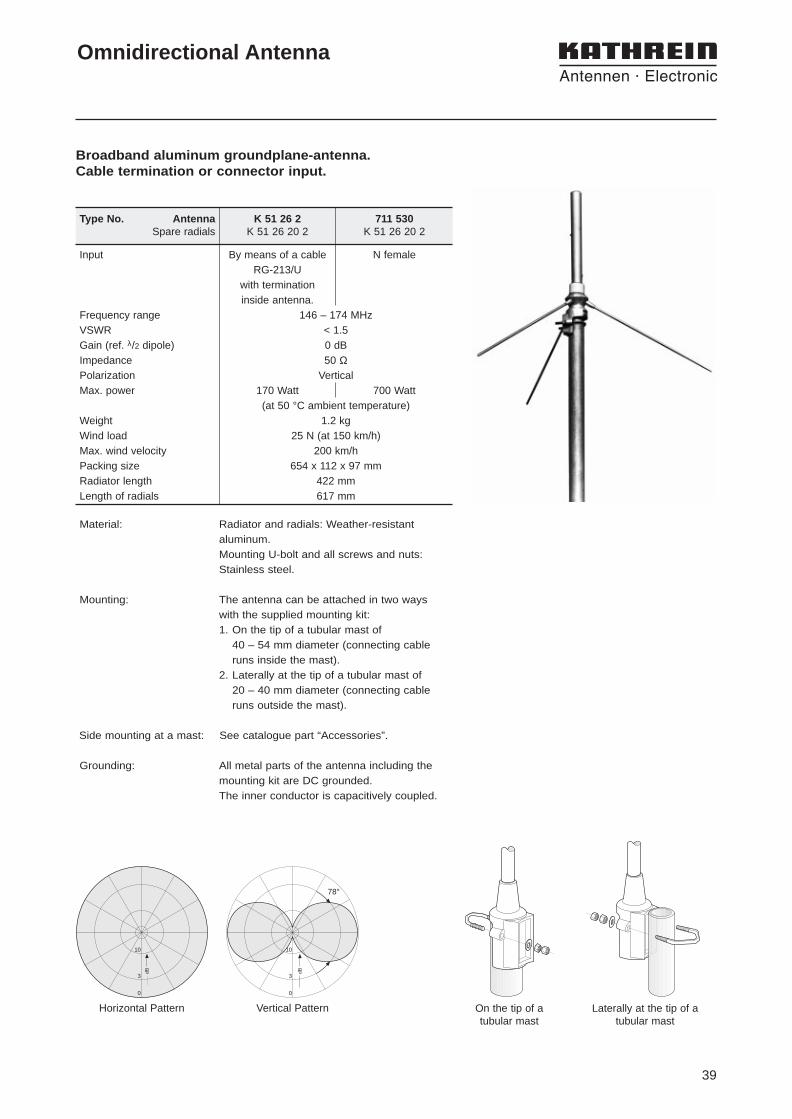
Broadband aluminum groundplane-antenna. Cable termination or connector input.
On the tip of a tubular mast
Laterally at the tip of atubular mast
Type No. Antenna K 51 26 2 711 530Spare radials K 51 26 20 2 K 51 26 20 2
Input By means of a cable N femaleRG-213/U
with terminationinside antenna.
Frequency range 146 – 174 MHzVSWR < 1.5Gain (ref. λ/2 dipole) 0 dBImpedance 50 ΩPolarization VerticalMax. power 170 Watt 700 Watt
(at 50 °C ambient temperature)Weight 1.2 kgWind load 25 N (at 150 km/h)Max. wind velocity 200 km/hPacking size 654 x 112 x 97 mmRadiator length 422 mmLength of radials 617 mm
Material: Radiator and radials: Weather-resistantaluminum.Mounting U-bolt and all screws and nuts:Stainless steel.
Mounting: The antenna can be attached in two ways with the supplied mounting kit:1. On the tip of a tubular mast of
40 – 54 mm diameter (connecting cableruns inside the mast).
2. Laterally at the tip of a tubular mast of 20 – 40 mm diameter (connecting cableruns outside the mast).
Side mounting at a mast: See catalogue part “Accessories”.
Grounding: All metal parts of the antenna including themounting kit are DC grounded.The inner conductor is capacitively coupled.
40
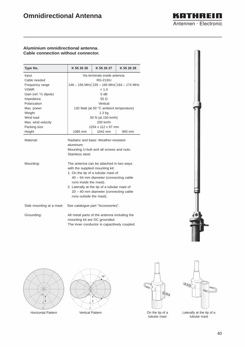
Aluminium omnidirectional antenna. Cable connection without connector.
10
3
0
dB dB
78°
10
3
0
On the tip of a tubular mast
Laterally at the tip of atubular mast
Omnidirectional Antenna
Horizontal Pattern Vertical Pattern
Type No. K 55 26 26 K 55 26 27 K 55 26 28
Input Via terminals inside antenna.Cable needed RG-213/UFrequency range 146 – 156 MHz 155 – 165 MHz 164 – 174 MHzVSWR < 1.4Gain (ref. λ/2 dipole) 0 dBImpedance 50 ΩPolarization VerticalMax. power 130 Watt (at 50 °C ambient temperature)Weight 1.3 kgWind load 50 N (at 150 km/h)Max. wind velocity 200 km/hPacking size 1254 x 112 x 97 mmHeight 1085 mm 1042 mm 993 mm
Material: Radiator and base: Weather-resistantaluminum.Mounting U-bolt and all screws and nuts:Stainless steel.
Mounting: The antenna can be attached in two ways with the supplied mounting kit:1. On the tip of a tubular mast of
40 – 54 mm diameter (connecting cableruns inside the mast).
2. Laterally at the tip of a tubular mast of 20 – 40 mm diameter (connecting cableruns outside the mast).
Side mounting at a mast: See catalogue part “Accessories”.
Grounding: All metal parts of the antenna including themounting kit are DC grounded.The inner conductor is capacitively coupled.

41
Type No. K 55 16 21 1 K 55 16 22 1 K 55 16 23 1
Input N femaleFrequency range 146 – 155 MHz 155 – 164 MHz 164 – 174 MHzVSWR < 1.5Gain (ref. λ/2 dipole) 4 dBImpedance 50 ΩPolarization VerticalMax. power 500 Watt (at 50 °C ambient temperature)Weight 7 kg 6.5 kg 6.5 kgWind load 280 N 270 N 250 N
(at 150 km/h)Max. wind velocity 150 km/hPacking size (L) 5011 mm 4826 mm 4511 mmPacking size (w x d) 198 x 152 mmAntenna height 4830 mm 4645 mm 4330 mmDiameter max. 52 mm
Omnidirectional gain antenna in fiberglass radome.Universal mounting.
10
3
0
dB 3 dB
10
0
21°
Laterally at the tip of atubular mast
On the tip of a tubular mast
Omnidirectional Gain Antenna
Horizontal Pattern Vertical Pattern
Material: Radiator: Brass.Radome: Fiberglass, colour:Grey.Base: Aluminum.Mounting U-bolt and all screws and nuts:Stainless steel.
Mounting: The antenna can be attached in two ways with the supplied mounting kit:1. On the tip of a tubular mast of
65 – 105 mm diameter (connecting cable runsinside the mast).
2. Laterally at the tip of a tubular mast of 30 – 90 mm diameter (connecting cable runsoutside the mast).
Grounding: All metal parts of the antenna including themounting kit are DC grounded.
42
Offset-pattern antenna. Hot-dip galvanized steel.
3 dB
10
0
3 dB
10
0
Horizontal Pattern60 mm diameter
Horizontal Pattern115 mm diameter
3 dB
10
0
78°
3 dB
10
0
78°
Vertical Pattern60 mm diameter
Vertical Pattern115 mm diameter
Radiation Pattern with different mast diameters:
Half-wave Dipole
Type No. K 55 29 21
Input N femaleFrequency range 146 – 174 MHzVSWR < 1.4Gain (ref. λ/2 dipole) 2 dBImpedance 50 ΩPolarization VerticalMax. power 440 Watt (at 50 °C ambient temperature)Radiation Pattern Preferred direction: Mast to radiator.Weight 4.5 kgWind load 90 N (at 150 km/h)Max. wind velocity 200 km/hPacking size 864 x 598 x 87 mmDipole length 840 mmDistance dipole / mast 500 mm
Material: Hot-dip galvanized steel.All screws and nuts: Stainless steel.
Mounting: On masts of 60 – 125 mm diameterclamps supplied.
Grounding: All metal parts of the antenna including themounting kit are DC grounded.

43
Type Type No. Frequency Range Height Input Max. Power Page
Summary of Omnidirectional Antennas
370 – 470 MHz
Indoor 420 360° 2 dBi 737 299 406 – 430 MHz 404 mm cable termination 50 Watt 44
Indoor 450 360° 2 dBi 736 831 450 – 470 MHz 364 mm cable termination 50 Watt 44
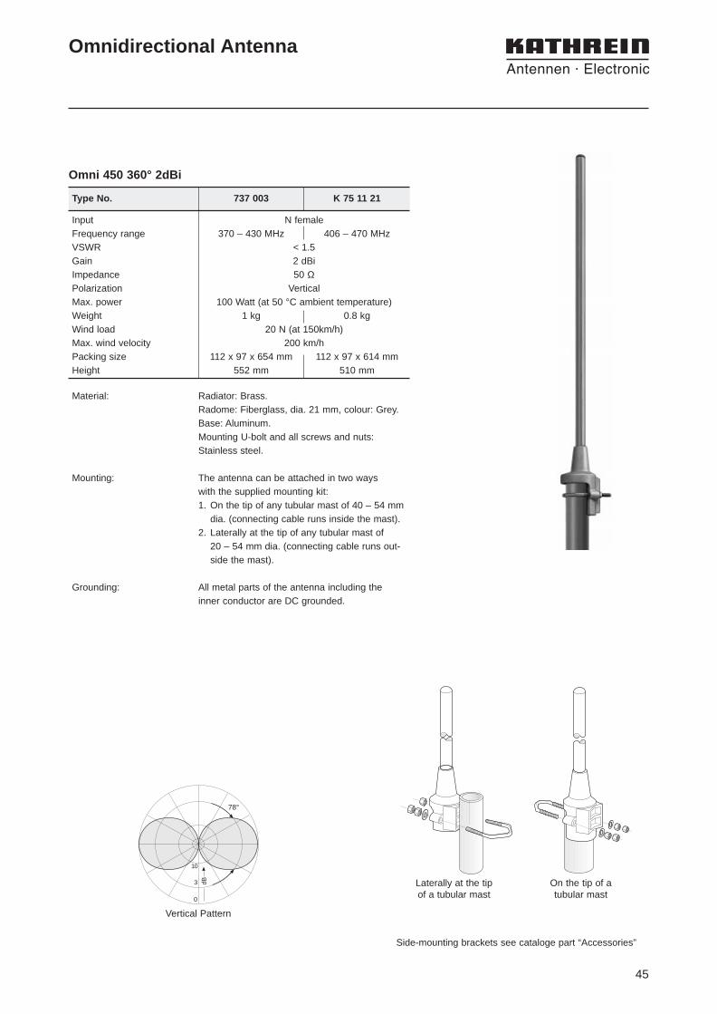
Omni 390/420 360° 2 dBi 737 003 370 – 430 MHz 552 mm N female 100 Watt 45
Omni 420/450 360° 2 dBi K 75 11 21 406 – 470 MHz 510 mm N female 100 Watt 45
Omni 420 360° 5 dBi K 75 15 21 1 406 – 430 MHz 1273 mm N female 55 Watt 46
Omni 450 360° 5 dBi K 75 15 22 1 440 – 470 MHz 1144 mm N female 55 Watt 46
Omni 450 360° 5 dBi 721 387 440 – 470 MHz 1144 mm N female 500 Watt 46
Omni 420 360° 7 dBi K 75 16 21 1 406 – 430 MHz 2016 mm N female 70 Watt 47
Omni 420 360° 7 dBi 728 888 406 – 430 MHz 2016 mm 7-16 female 500 Watt 47
Omni 420/450 360° 7 dBi K 75 16 22 1 420 – 449 MHz 1975 mm N female 70 Watt 47
Omni 450 360° 7 dBi K 75 16 23 1 440 – 470 MHz 1868 mm N female 70 Watt 47
Omni 450 360° 7 dBi 721 388 440 – 470 MHz 2016 mm N female 500 Watt 47
Omni 450 360° 7 dBi 720 880 440 – 470 MHz 2016 mm 7-16 female 500 Watt 47
Omni 390 360° 7.5 dBi K 75 16 37 380 – 400 MHz 2840 mm 7-16 female 500 Watt 48
Omni 450 360° 8.5 dBi 742 155 450 – 470 MHz 3110 mm 7-16 female 500 Watt 49
Omni 420 360° 10 dBi 728 889 406 – 430 MHz 4430 mm 7-16 female 500 Watt 50
Omni 450 360° 10 dBi 720 842 440 – 470 MHz 4175 mm 7-16 female 500 Watt 50
Offset- 420/450 360° 4 dBi K 75 29 21 400 – 470 MHz 314 mm 7-16 female 450 Watt 51pattern

44
min. Ø 22
Ceiling
90
Ø 5,5
Mounting plate
Indoor Omnidirectional Antenna
• The antenna does not require any additional groundplane.
b)a)
Input Cable RG 58/CU of 1 m length, grey,connector is not supplied
Frequency range 406 – 430 MHz 450 – 470 MHzVSWR < 1.5Gain 2 dBiImpedance 50 ΩPolarization VerticalMax. power 50 Watt (at 50 °C ambient temperature)Weight 0.25 kg 0.23 kgMounting plate 115 x 25 mmPacking size Foil: 650 x 130 mmHeight/Radome dia. 404 mm/20 mm 369 mm/20 mm
Type No. 737 299 736 831
max.10 mm Ceiling
90
Material: Radiator: Brass.Radome: Fiberglass, colour: White.Mounting plate: Aluminum.
Mounting: a) Single-hole mounting (12 mm diameter) onsurface of up to 10 mm thickness.
b) On surfaces of more than 10 mm thickness,by means of mounting plate included in thescope of delivery.
Grounding: All metal parts of the antenna including the innerconductor are DC grounded.
Indoor 450 360° 2dBi
45
3 dB
10
0
78°
Omni 450 360° 2dBi
Side-mounting brackets see cataloge part “Accessories”
Omnidirectional Antenna
Vertical Pattern
On the tip of atubular mast
Laterally at the tip of a tubular mast
Material: Radiator: Brass.Radome: Fiberglass, dia. 21 mm, colour: Grey.Base: Aluminum.Mounting U-bolt and all screws and nuts:Stainless steel.
Mounting: The antenna can be attached in two ways with the supplied mounting kit:1. On the tip of any tubular mast of 40 – 54 mm
dia. (connecting cable runs inside the mast).2. Laterally at the tip of any tubular mast of
20 – 54 mm dia. (connecting cable runs out-side the mast).
Grounding: All metal parts of the antenna including the inner conductor are DC grounded.
Input N femaleFrequency range 370 – 430 MHz 406 – 470 MHzVSWR < 1.5Gain 2 dBiImpedance 50 ΩPolarization VerticalMax. power 100 Watt (at 50 °C ambient temperature)Weight 1 kg 0.8 kgWind load 20 N (at 150km/h)Max. wind velocity 200 km/hPacking size 112 x 97 x 654 mm 112 x 97 x 614 mmHeight 552 mm 510 mm
Type No. 737 003 K 75 11 21

46
Input N female N femaleFrequency range 406 – 430 MHz 440 – 470 MHzVSWR < 1.5Gain 5 dBiImpedance 50 ΩPolarization VerticalMax. power 55 Watt 55 Watt 500 Watt
(at 50 °C ambient temperature)Weight 1.2 kgWind load 40 N (at 150 km/h) 35 N (at 150 km/h)Max. wind velocity 200 km/h 200 km/hPacking size 1350 x 110 x 100 mm 1250 x 110 x 100 mmAntenna height 1273 mm 1144 mm
Type No. K 75 15 21 1 K 75 15 22 1 721 387
3 dB
10
0
30°
Omni 450 360° 5dBi
Omnidirectional Antenna
Material: Radiator: Brass.Radome: Fiberglass, dia. 21 mm, colour: Grey.
Base: Aluminum.Mounting U-bolt and all screws and nuts: Stainless steel.
Mounting: The antenna can be attached in two ways with the suppliedmounting kit:1. On the tip of any tubular mast of 40 – 54 mm dia. (con-
necting cable runs inside the mast).2. Laterally at the tip of any tubular mast of 20 – 54 mm
dia. (connecting cable runs outside the mast).
Grounding: All metal parts of the antenna including the inner conductorare DC grounded.
Vertical Pattern
On the tip of a tubular mast
Laterally at the tip of a tubular mast
Side-mounting brackets see cataloge part “Accessories”
47
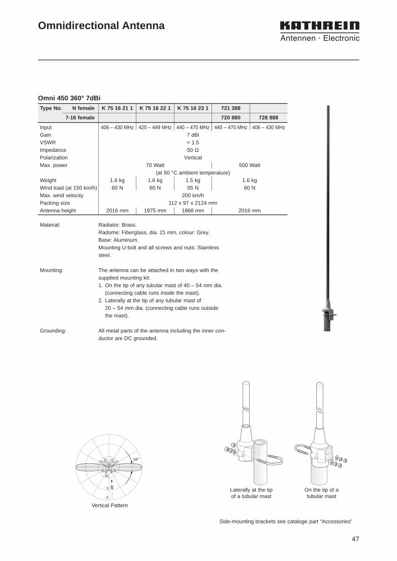
Omnidirectional Antenna
Input 406 – 430 MHz 420 – 449 MHz 440 – 470 MHz 440 – 470 MHz 406 – 430 MHzGain 7 dBiVSWR < 1.5Impedance 50 ΩPolarization VerticalMax. power 70 Watt 500 Watt
(at 50 °C ambient temperature)Weight 1.6 kg 1.6 kg 1.5 kg 1.6 kgWind load (at 150 km/h) 60 N 60 N 55 N 60 NMax. wind velocity 200 km/hPacking size 112 x 97 x 2124 mmAntenna height 2016 mm 1975 mm 1868 mm 2016 mm
Type No. N female K 75 16 21 1 K 75 16 22 1 K 75 16 23 1 721 388
7-16 female 720 880 728 888
Vertical Pattern
3 dB
10
0
18°
Omni 450 360° 7dBi
Material: Radiator: Brass.Radome: Fiberglass, dia. 21 mm, colour: Grey.Base: Aluminum.Mounting U-bolt and all screws and nuts: Stainlesssteel.
Mounting: The antenna can be attached in two ways with thesupplied mounting kit:1. On the tip of any tubular mast of 40 – 54 mm dia.
(connecting cable runs inside the mast).2. Laterally at the tip of any tubular mast of
20 – 54 mm dia. (connecting cable runs outsidethe mast).
Grounding: All metal parts of the antenna including the inner con-ductor are DC grounded.
On the tip of a tubular mast
Laterally at the tip of a tubular mast
Side-mounting brackets see cataloge part “Accessories”

48
Input 7-16 femaleFrequency range 380 – 400 MHzVSWR < 1.5Gain 7.5 dBiImpedance 50 ΩPolarization VerticalMax. power 500 Watt (at 50 °C ambient temperature)Weight 8 kgWind load 200 N (at 150 km/h)Max. wind velocity 200 km/hPacking size 3316 x 148 x 112 mmAntenna height 2840 mm
Type No. K 75 16 37
• Maximum power: 500 Watt.• Grounding cross section: 22 mm 2 copper.
Omnidirectional Antenna
dB
15°
10
3
0
Material: Radiator: Copper and brass.Radome: Fiberglass, dia. 51 mm, colour: Grey.Base: Aluminum.Mounting kit, screws and nuts: Stainless steel.
Mounting: The antenna can be attached laterally at the tipof any tubular mast of 50 – 94 mm diameter(connecting cable runs outside the mast).
Grounding: The antenna is DC grounded via a copper tubehaving a cross-sectional area of 22 mm2.The inner conductor is capacitively coupled.
Vertical Pattern
Side-mounting brackets see cataloge part “Accessories”
150
230
104
maximum
mast top
Omni 450 360° 7.5dBi
49
Side-mounting brackets see cataloge part “Accessories”
Omnidirectional Antenna
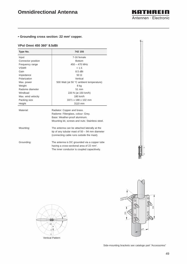
VPol Omni 450 360° 8.5dBi
Type No. 742 155
Material: Radiator: Copper and brass.Radome: Fiberglass, colour: Grey.Base: Weather-proof aluminum.Mounting kit, screws and nuts: Stainless steel.
Mounting: The antenna can be attached laterally at the tip of any tubular mast of 50 – 94 mm diameter(connecting cable runs outside the mast).
Grounding: The antenna is DC grounded via a copper tubehaving a cross-sectional area of 22 mm2.The inner conductor is coupled capacitively.
Input 7-16 femaleConnector position BottomFrequency range 450 – 470 MHzVSWR < 1.5Gain 8.5 dBiImpedance 50 ΩPolarization VerticalMax. power 500 Watt (at 50 °C ambient temperature)Weight 8 kgRadome diameter 51 mmWindload 220 N (at 150 km/h)Max. wind velocity 180 km/hPacking size 3371 x 188 x 102 mmHeight 3110 mm
3 dB
10
0
12°
Vertical Pattern
• Grounding cross section: 22 mm 2 copper.
150
230
104
maximum
mast top

50
Vertical Pattern
3 dB
10
0
8°
• Maximum power: 500 Watt.
Omnidirectional Antenna
Type No. 728 889 720 842
Input 7 – 16 female 7 – 16 femaleFrequency range 406 – 430 MHz 440 – 470 MHzVSWR < 1.5Gain 10 dBiImpedance 50 ΩPolarization VerticalMax. power 500 Watt (at 50 °C ambient temperature)Weight 7 kg 6.5 kgWind load 240 N (at 150 km/h) 230 N (at 150 km/h)Max. wind velocity 150 km/hPacking size 4600 x 198 x 152 mmAntenna height 4430 mm 4175 mm
Side-mounting brackets see cataloge part “Accessories”
On the tip of a tubular mast
Laterally at the tip of a tubular mast
Material: Radiator: Brass.Radome: Fiberglass, dia. 30 – 52 mm, colour: Grey. Base: Aluminum.Mounting U-bolt and all screws and nuts:Stainless steel.
Mounting: The antenna can be attached in two ways with the supplied mounting kit:1. On the tip of any tubular mast of 65 – 105 mm
dia. (connecting cable runs inside the mast).2. Laterally at the tip of any tubular mast of
30 – 90 mm dia. (connecting cable runs out-side the mast).
Grounding: All metal parts of the antenna including the innerconductor are DC grounded.
Omni 450 360° 10dBi

51
Side-mounted Half-wave Dipole
Type No. K 75 29 21
Input N femaleFrequency range 400 – 470 MHzVSWR < 1.5Gain approx. 4 dBiImpedance 50 ΩPolarization VerticalMax. power 450 Watt (at 50 °C ambient temperature)Weight 1.6 kgWind load 40 N (at150 km/h)Max. wind velocity 200 km/hPacking size 880 x 330 x 100 mmAntenna height 314 mm
Abstand A
Material: Radiator: Hot-dip galvanized steel.Horizontal support pipe: Stainless steel.Mount: Aluminum. Tightening band and all screws and nuts:Stainless steel.Feedpoint radome: Fiberglass.
Attachment: To tubular masts of 60 – 320 mm diameter using supplied stainless steel tightening band(20 mm wide, 0.8 mm gauge).
Special features: The distance from tubular mast to radiator isadjustable from 170 – 580 mm. Detailed information see Catalogue part“Technical Supplement”
Grounding: All metal parts of the antenna including the innerconductor and the supplied mounting hardwareare DC grounded.
• Side-mounted half-wave dipole with variable antenna-to-mast distance.• Depending on the distance of the radiator from the mast edge and also
on the mast diameter, various radiation patterns can be achieved.
Radiation pattern depending on the distance A(edge of pipe mast to dipole).
Distance A
Offset-Pattern 420/450 360° 4dBi

52
53
Type Type No. Frequency Range Height Input Max. Power Page
Type Type No. Frequency Range Height Input Max. Power Page
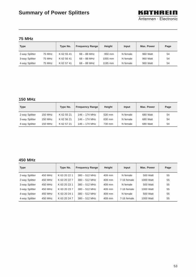
Summary of Power Splitters
75 MHz
2-way Splitter 75 MHz K 62 55 41 68 – 88 MHz 950 mm N female 960 Watt 54
3-way Splitter 75 MHz K 62 56 41 68 – 88 MHz 1055 mm N female 960 Watt 54
4-way Splitter 75 MHz K 62 57 41 68 – 88 MHz 1195 mm N female 960 Watt 54
Type Type No. Frequency Range Height Input Max. Power Page
2-way Splitter 450 MHz K 63 20 22 1 380 – 512 MHz 409 mm N female 500 Watt 55
2-way Splitter 450 MHz K 63 20 22 7 380 – 512 MHz 409 mm 7-16 female 1000 Watt 55
3-way Splitter 450 MHz K 63 20 23 1 380 – 512 MHz 409 mm N female 500 Watt 55
3-way Splitter 450 MHz K 63 20 23 7 380 – 512 MHz 409 mm 7-16 female 1000 Watt 55
4-way Splitter 450 MHz K 63 20 24 1 380 – 512 MHz 409 mm N female 500 Watt 55
4-way Splitter 450 MHz K 63 20 24 7 380 – 512 MHz 409 mm 7-16 female 1000 Watt 55
150 MHz
2-way Splitter 150 MHz K 62 55 21 146 – 174 MHz 530 mm N female 680 Watt 54
3-way Splitter 150 MHz K 62 56 21 146 – 174 MHz 630 mm N female 680 Watt 54
4-way Splitter 150 MHz K 62 57 21 146 – 174 MHz 730 mm N female 680 Watt 54
450 MHz
54
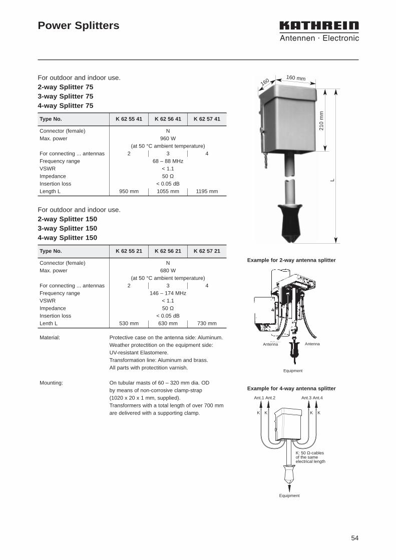
For outdoor and indoor use.2-way Splitter 75 3-way Splitter 75 4-way Splitter 75
Connector (female) NMax. power 680 W
(at 50 °C ambient temperature)For connecting ... antennas 2 3 4Frequency range 146 – 174 MHzVSWR < 1.1Impedance 50 ΩInsertion loss < 0.05 dBLenth L 530 mm 630 mm 730 mm
Power Splitters
Connector (female) NMax. power 960 W
(at 50 °C ambient temperature)For connecting ... antennas 2 3 4Frequency range 68 – 88 MHzVSWR < 1.1Impedance 50 ΩInsertion loss < 0.05 dBLength L 950 mm 1055 mm 1195 mm
Type No. K 62 55 41 K 62 56 41 K 62 57 41
160 mm160
L
210
mm
For outdoor and indoor use.2-way Splitter 150 3-way Splitter 150 4-way Splitter 150
Type No. K 62 55 21 K 62 56 21 K 62 57 21
Example for 4-way antenna splitter
Equipment
AntennaAntenna
Example for 2-way antenna splitter
Material: Protective case on the antenna side: Aluminum.Weather protectition on the equipment side: UV-resistant Elastomere.Transformation line: Aluminum and brass.All parts with protectition varnish.
Mounting: On tubular masts of 60 – 320 mm dia. OD by means of non-corrosive clamp-strap (1020 x 20 x 1 mm, supplied).Transformers with a total length of over 700 mmare delivered with a supporting clamp.
Ant.1 Ant.2 Ant.3 Ant.4
K K K K
Equipment
K: 50 Ω-cablesof the sameelectrical length

55
For outdoor and indoor use.2-way Splitter 390/420/4503-way Splitter 390/420/4504-way Splitter 390/420/450
Connectors (female) N 7-16 N 7-16 N 7-16Max. power 500 W 1000 W 500 W 1000 W 500 W 1000 W
(at 50 °C ambient temperature)For connecting ... antennas 2 3 4Frequency range 380 – 512 MHzVSWR < 1.1Impedance 50 ΩInsertion loss < 0.05 dBPacking size 425 x 93 x 107 mmMax. size 409 x 82 x 82 mm
Type No. K 63 20 22 1 K 63 20 22 7 K 63 20 23 1 K 63 20 23 7 K 63 20 24 1 K 63 20 24 7
734 360 2 clamps 30 – 55 mm734 361 2 clamps 55 – 75 mm734 362 2 clamps 75 – 95 mm734 363 2 clamps 95 – 115 mm734 364 2 clamps 115 – 135 mm
Type No. Description Mast Diameter
Clamps
734 364
K 63 20 24 7
Power Splitters
Material: Case: Aluminum.Inner conductor: Brass.
Mounting: Bracket for wall mounting included in the scope of supply.For mounting to tubular masts use clamps as listed below(order separately).

56

57
Downtilt 737 973 974 mm 0 – 21° 64737 975 1934 mm 0 – 11° 64737 976 2574 mm 0 – 8° 64
Azimuth adjustment tool 738 440 115 – 245 mm 65
Accessories
Brackets
Bracket with fixed spacing K 61 33 3 500 mm 55 – 105 mm 66716 192 500 mm 105 – 245 mm 66
K 61 33 4 1000 mm 55 – 105 mm 66713 645 1000 mm 105 – 245 mm 66
Bracket with adjustable spacing K 61 33 11 125 – 680 mm 20 – 54 mm 66K 61 33 21 125 – 680 mm 30 – 90 mm 66
737 398 100 – 240 mm 50 – 94 mm 66
Type Type No. Distance Mast Diameter Page
Accessories for PanelsDimensions
Mounting hardware K 61 14 01 1.6 kg 40 mm... ... ...
K 61 14 05 10.2 kg 521 mm 59
Type Type No. Weight For Mast Diameter Page
Type Type No. Antenna Height Downtilt Angle Page
Mounting Accessories
Accessories for Eurocell PanelsDimensions
Mounting hardware 731 651 300 g 28 – 64 mm 63738 546 1 kg 50 – 115 mm 63733 677 2 kg 60 mm
... ... ...733 680 5.3 kg 521 mm 63
Type Type No. Weight For Mast Diameter Page
Type Type No. Antenna Height Downtilt Angle Page
Mounting Accessories
Downtilt 732 574 1000 mm 2 – 20° 592000 mm 1 – 10° 59
Downtilt 733 695 992 mm 0 – 22° 602000 mm 0 – 11° 60
58
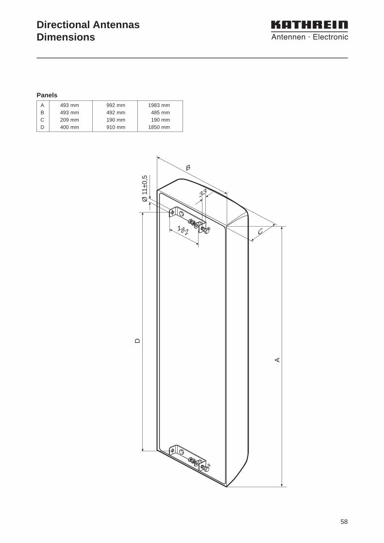
Directional AntennasDimensions
A 493 mm 992 mm 1983 mmB 493 mm 492 mm 485 mmC 209 mm 190 mm 190 mmD 400 mm 910 mm 1850 mm
Panels
B
182
A
Ø 1
1±0,
5D
33
C
59
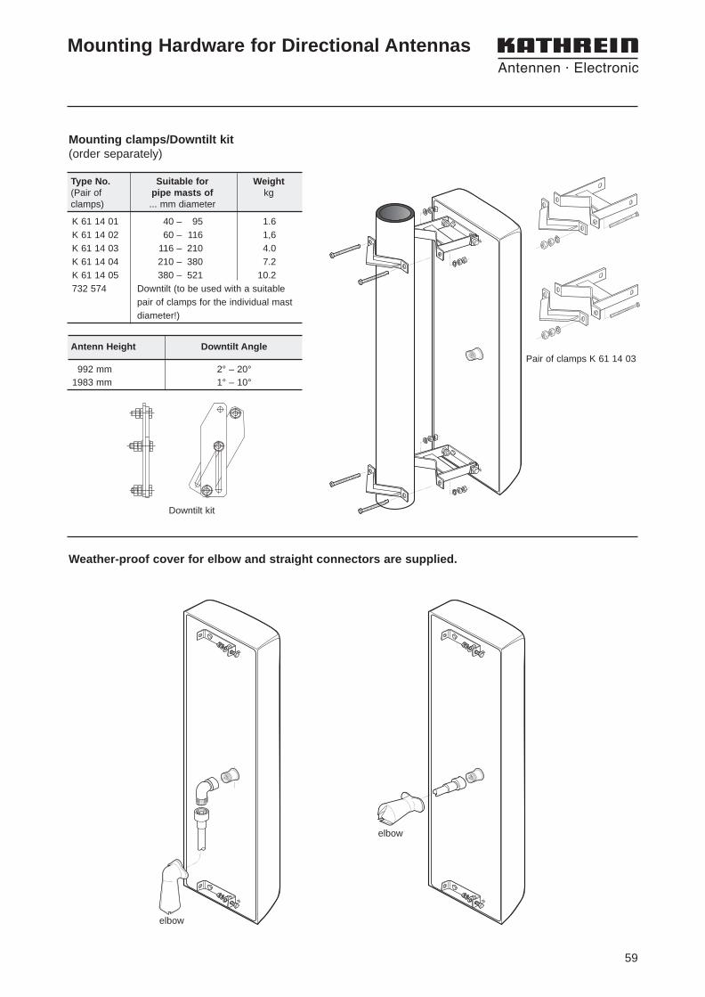
Type No. Suitable for Weight(Pair of pipe masts of kgclamps) ... mm diameter
992 mm 2° – 20°1983 mm 1° – 10°
Mounting Hardware for Directional Antennas
K 61 14 01 40 – 95 1.6 K 61 14 02 60 – 116 1,6 K 61 14 03 116 – 210 4.0 K 61 14 04 210 – 380 7.2 K 61 14 05 380 – 521 10.2 732 574 Downtilt (to be used with a suitable
pair of clamps for the individual mast diameter!)
Weather-proof cover for elbow and straight connectors are supplied.
Mounting clamps/Downtilt kit(order separately)
Antenn Height Downtilt AnglePair of clamps K 61 14 03
elbow
elbow
Downtilt kit

60
K 61 14 01 40 – 95 1.6 K 61 14 02 60 – 116 1,6 K 61 14 03 116 – 210 4.0 K 61 14 04 210 – 380 7.2 K 61 14 05 380 – 521 10.2 733 695 Downtilt (to be used with a suitable
pair of clamps for the individual mast diameter!)
Weather-proof cover for elbow and straight con-nectors are supplied.
Mounting clamps/Downtilt kit(order separately)
Type No. Suitable for Weight(Pair of pipe masts of kgclamps) ... mm diameter
Antenna Height Downtilt Angle
992 mm 0° – 22°1983 mm 0° – 11°
straight
elbow
Mounting Hardware for Directional Antennaswith Dual-Polarization741 515, 741 516
Downtilt kit 733 695
Pair of clamps K 61 14 03
61
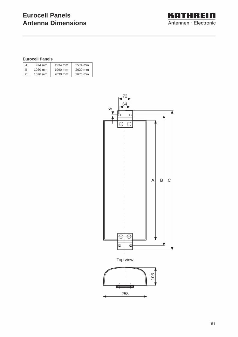
Eurocell PanelsAntenna Dimensions
A 974 mm 1934 mm 2574 mmB 1030 mm 1990 mm 2630 mmC 1070 mm 2030 mm 2670 mm
Eurocell Panels
64
72
9
A B C
258
Top view
103
62
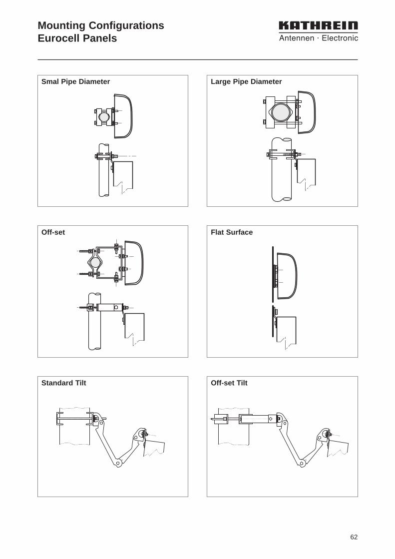
Smal Pipe Diameter
Flat Surface
Large Pipe Diameter
Off-set
Standard Tilt Off-set Tilt
Mounting ConfigurationsEurocell Panels
63
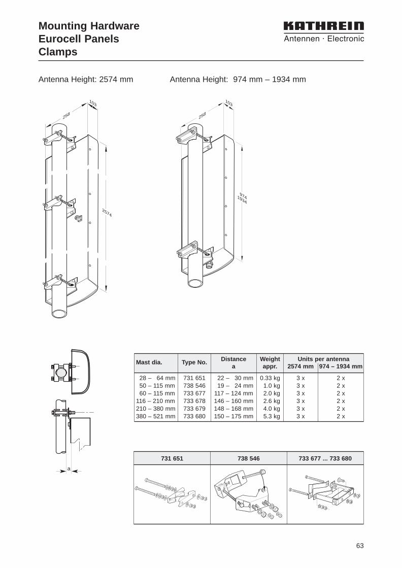
Antenna Height: 2574 mm Antenna Height: 974 mm – 1934 mm
Mounting HardwareEurocell PanelsClamps
731 651 738 546 733 677 ... 733 680
28 – 64 mm 731 651 22 – 30 mm 0.33 kg 3 x 2 x50 – 115 mm 738 546 19 – 24 mm 1.0 kg 3 x 2 x60 – 115 mm 733 677 117 – 124 mm 2.0 kg 3 x 2 x
116 – 210 mm 733 678 146 – 160 mm 2.6 kg 3 x 2 x210 – 380 mm 733 679 148 – 168 mm 4.0 kg 3 x 2 x380 – 521 mm 733 680 150 – 175 mm 5.3 kg 3 x 2 x
Distance Weight Units per antenna Mast dia. Type No.a appr. 2574 mm 974 – 1934 mm
258
103
2574
258
103
9741934
a
64
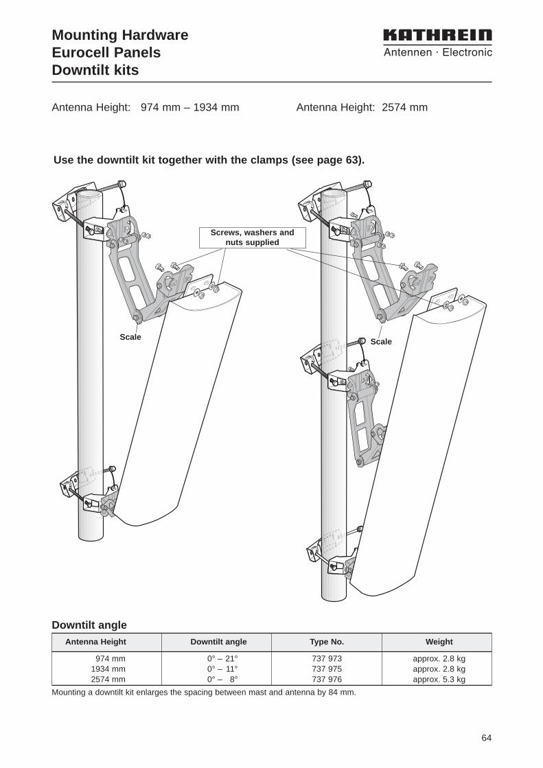
974 mm 0° – 21° 737 973 approx. 2.8 kg1934 mm 0° – 11° 737 975 approx. 2.8 kg2574 mm 0° – 8° 737 976 approx. 5.3 kg
Antenna Height Downtilt angle Type No. Weight
Downtilt angle
Mounting a downtilt kit enlarges the spacing between mast and antenna by 84 mm.
Use the downtilt kit together with the clamps (see page 63).
036
912
1520
Scale
036
912
1520
Scale
Screws, washers and nuts supplied
Mounting HardwareEurocell PanelsDowntilt kits
Antenna Height: 974 mm – 1934 mm Antenna Height: 2574 mm
65
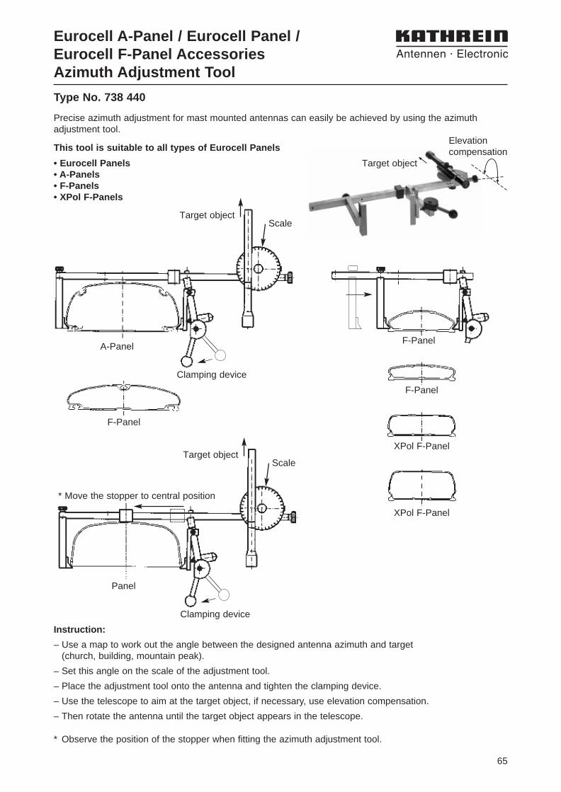
Elevationcompensation
Precise azimuth adjustment for mast mounted antennas can easily be achieved by using the azimuth adjustment tool.
Eurocell A-Panel / Eurocell Panel /Eurocell F-Panel AccessoriesAzimuth Adjustment Tool
This tool is suitable to all types of Eurocell Panels
• Eurocell Panels• A-Panels• F-Panels• XPol F-Panels
Instruction:
– Use a map to work out the angle between the designed antenna azimuth and target (church, building, mountain peak).
– Set this angle on the scale of the adjustment tool.
– Place the adjustment tool onto the antenna and tighten the clamping device.
– Use the telescope to aim at the target object, if necessary, use elevation compensation.
– Then rotate the antenna until the target object appears in the telescope.
* Observe the position of the stopper when fitting the azimuth adjustment tool.
F-Panel
F-Panel
Clamping device
Scale
Panel
* Move the stopper to central position
Target object
F-Panel
Clamping device
Scale
A-Panel
Target object
XPol F-Panel
XPol F-Panel
Type No. 738 440
Target object
66
L 30 x 4
100 to240 mm
Pipe70 x 4 mmfree length250 mm
L 30 x 4
245 mm
1
2
AccessoriesStand-off Brackets
1015 mm
515 mm
K 61 33 3
K 61 33 4
95
pipe diameter
44.5 x 2.6 mm
pipe diameter
44.5 x 2.6 mm
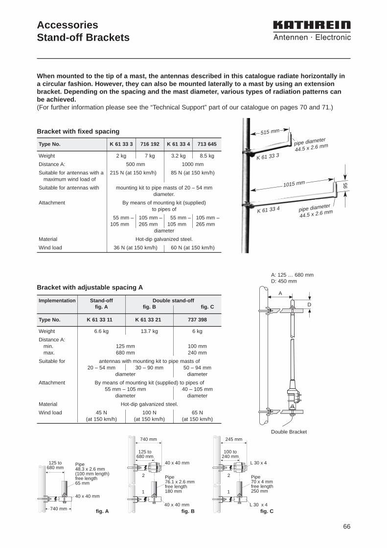
Weight 6.6 kg 13.7 kg 6 kg
Distance A:min. 125 mm 100 mmmax. 680 mm 240 mm
Suitable for antennas with mounting kit to pipe masts of20 – 54 mm 30 – 90 mm 50 – 94 mm
diameter diameter
Attachment By means of mounting kit (supplied) to pipes of55 mm – 105 mm 40 – 105 mm
diameter diameter
Material Hot-dip galvanized steel.
Wind load 45 N 100 N 65 N (at 150 km/h) (at 150 km/h) (at 150 km/h)
When mounted to the tip of a mast, the antennas described in this catalogue radiate horizontally ina circular fashion. However, they can also be mounted laterally to a mast by using an extensionbracket. Depending on the spacing and the mast diameter, various types of radiation patterns canbe achieved. (For further information please see the “Technical Support” part of our catalogue on pages 70 and 71.)
2 kg 7 kg 3.2 kg 8.5 kg
500 mm 1000 mm
215 N (at 150 km/h) 85 N (at 150 km/h)
mounting kit to pipe masts of 20 – 54 mm diameter.
By means of mounting kit (supplied)to pipes of
55 mm – 105 mm – 55 mm – 105 mm –105 mm 265 mm 105 mm 265 mm
diameter
Hot-dip galvanized steel.
36 N (at 150 km/h) 60 N (at 150 km/h)
Weight
Distance A:
Suitable for antennas with amaximum wind load of
Suitable for antennas with
Attachment
Material
Wind load
Type No. K 61 33 3 716 192 K 61 33 4 713 645
Bracket with fixed spacing
Bracket with adjustable spacing A
Implementation Stand-off Double stand-offfig. A fig. B fig. C
Type No. K 61 33 11 K 61 33 21 737 398
40 x 40 mm
740 mm
125 to680 mm
Pipe48.3 x 2.6 mm(100 mm length)free length65 mm
40 x 40 mm
125 to680 mm
Pipe76.1 x 2.6 mmfree length180 mm
40 x 40 mm
740 mm
1
2
fig. A fig. B fig. C
A
D
A: 125 … 680 mmD: 450 mm
Double Bracket
67
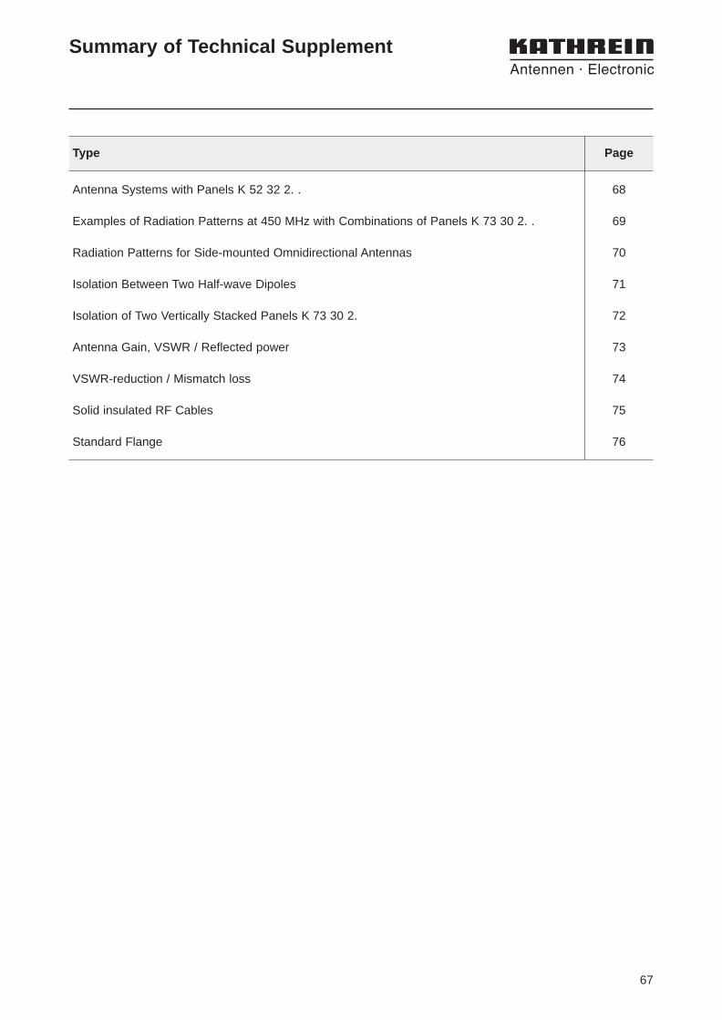
Antenna Systems with Panels K 52 32 2. . 68
Examples of Radiation Patterns at 450 MHz with Combinations of Panels K 73 30 2. . 69
Radiation Patterns for Side-mounted Omnidirectional Antennas 70
Isolation Between Two Half-wave Dipoles 71
Isolation of Two Vertically Stacked Panels K 73 30 2. 72
Antenna Gain, VSWR / Reflected power 73
VSWR-reduction / Mismatch loss 74
Solid insulated RF Cables 75
Standard Flange 76
Type Page
Summary of Technical Supplement
68
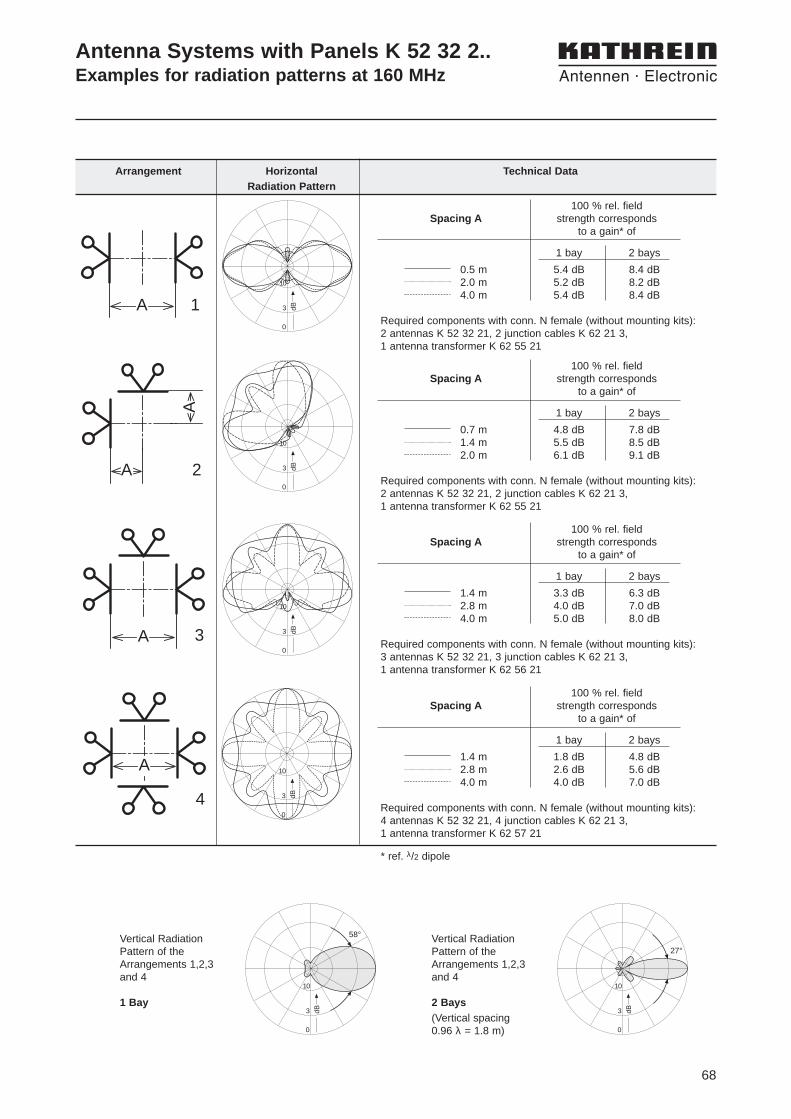
Antenna Systems with Panels K 52 32 2..Examples for radiation patterns at 160 MHz
Arrangement Horizontal Technical DataRadiation Pattern
A 1 3 dB10
0
100 % rel. field Spacing A strength corresponds
to a gain* of
1 bay 2 bays
0.5 m 5.4 dB 8.4 dB2.0 m 5.2 dB 8.2 dB4.0 m 5.4 dB 8.4 dB
Required components with conn. N female (without mounting kits):2 antennas K 52 32 21, 2 junction cables K 62 21 3, 1 antenna transformer K 62 55 21
A
A
2 3 dB
10
0
100 % rel. fieldSpacing A strength corresponds
to a gain* of
1 bay 2 bays
0.7 m 4.8 dB 7.8 dB1.4 m 5.5 dB 8.5 dB2.0 m 6.1 dB 9.1 dB
Required components with conn. N female (without mounting kits):2 antennas K 52 32 21, 2 junction cables K 62 21 3,1 antenna transformer K 62 55 21
A 3 3 dB
10
0
3 dB
10
0
100 % rel. fieldSpacing A strength corresponds
to a gain* of
1 bay 2 bays
1.4 m 3.3 dB 6.3 dB2.8 m 4.0 dB 7.0 dB4.0 m 5.0 dB 8.0 dB
Required components with conn. N female (without mounting kits): 3 antennas K 52 32 21, 3 junction cables K 62 21 3,1 antenna transformer K 62 56 21
A
4
3 dB
10
0
58°
100 % rel. fieldSpacing A strength corresponds
to a gain* of
1 bay 2 bays
1.4 m 1.8 dB 4.8 dB2.8 m 2.6 dB 5.6 dB4.0 m 4.0 dB 7.0 dB
Required components with conn. N female (without mounting kits): 4 antennas K 52 32 21, 4 junction cables K 62 21 3,1 antenna transformer K 62 57 21
* ref. λ/2 dipole
Vertical Radiation Pattern of the Arrangements 1,2,3 and 4
1 Bay3 dB
10
0
27°Vertical Radiation Pattern of theArrangements 1,2,3 and 4
2 Bays(Vertical spacing0.96 λ = 1.8 m)
69
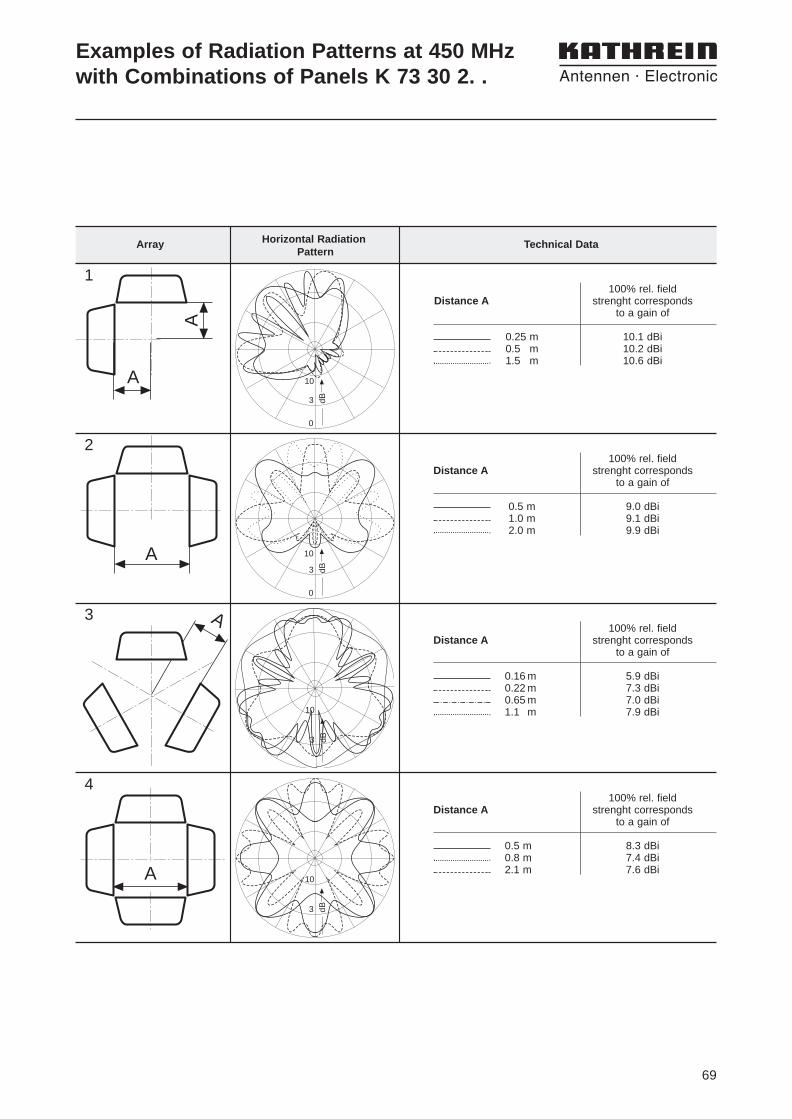
Examples of Radiation Patterns at 450 MHz with Combinations of Panels K 73 30 2. .
Horizontal RadiationArrayPattern
Technical Data
A
A
A
A
A
3 dB
0
10
3 dB
0
10
3 dB
10
3 dB
10
100% rel. fieldDistance A strenght corresponds
to a gain of
0.25 m 10.1 dBi0.5 m 10.2 dBi1.5 m 10.6 dBi
100% rel. fieldDistance A strenght corresponds
to a gain of
0.5 m 9.0 dBi1.0 m 9.1 dBi2.0 m 9.9 dBi
1
2
3
4
100% rel. fieldDistance A strenght corresponds
to a gain of
0.16 m 5.9 dBi0.22 m 7.3 dBi0.65 m 7.0 dBi1.1 m 7.9 dBi
100% rel. fieldDistance A strenght corresponds
to a gain of
0.5 m 8.3 dBi0.8 m 7.4 dBi2.1 m 7.6 dBi
70
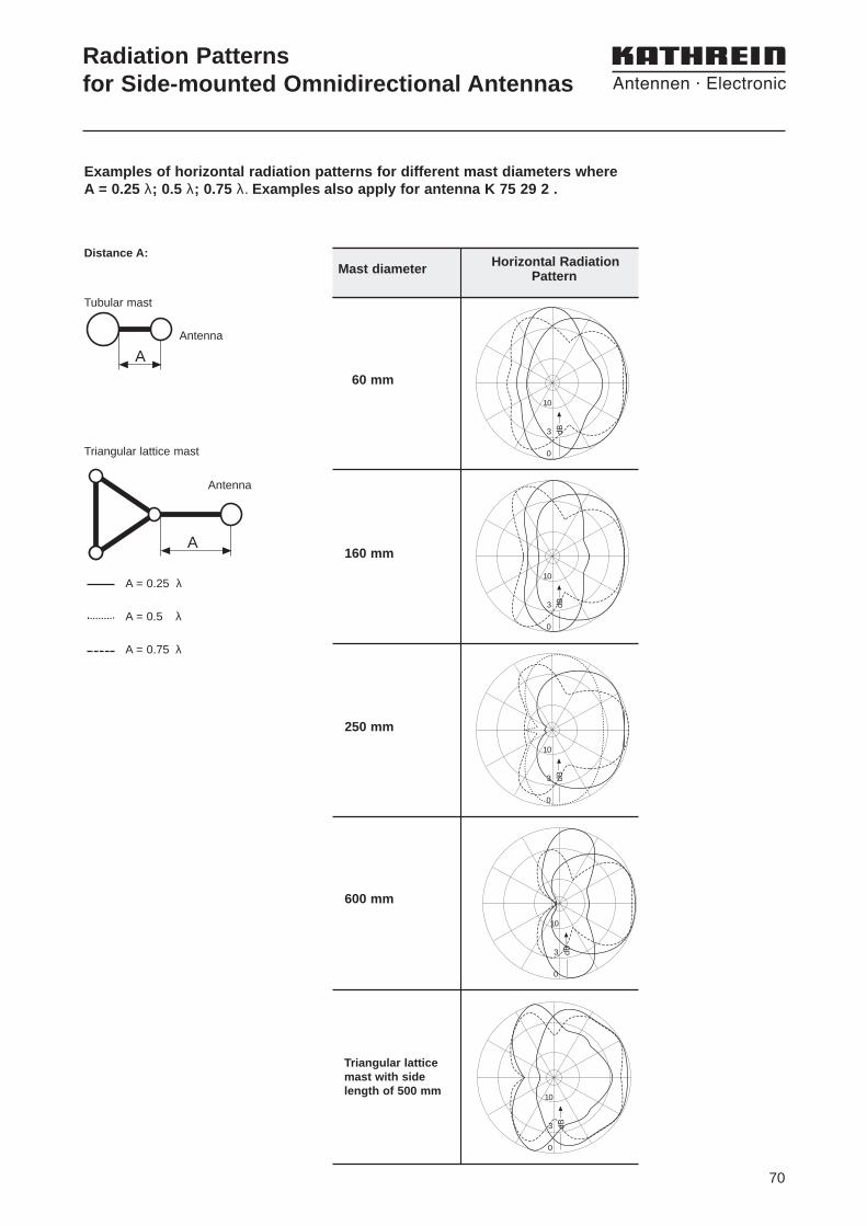
Radiation Patternsfor Side-mounted Omnidirectional Antennas
Examples of horizontal radiation patterns for different mast diameters where A = 0.25 λ; 0.5 λ; 0.75 λ. Examples also apply for antenna K 75 29 2 .
60 mm
160 mm
250 mm
600 mm
Triangular lattice mast with side length of 500 mm
3 dB
10
0
3 dB
10
0
3 dB
10
0
3 dB
10
0
3 dB
10
0
Distance A:
Tubular mast
Antenna
Triangular lattice mast
A = 0.25 λ
A = 0.5 λ
A = 0.75 λ
A
A
Antenna
Horizontal Radiation Mast diameter Pattern
71
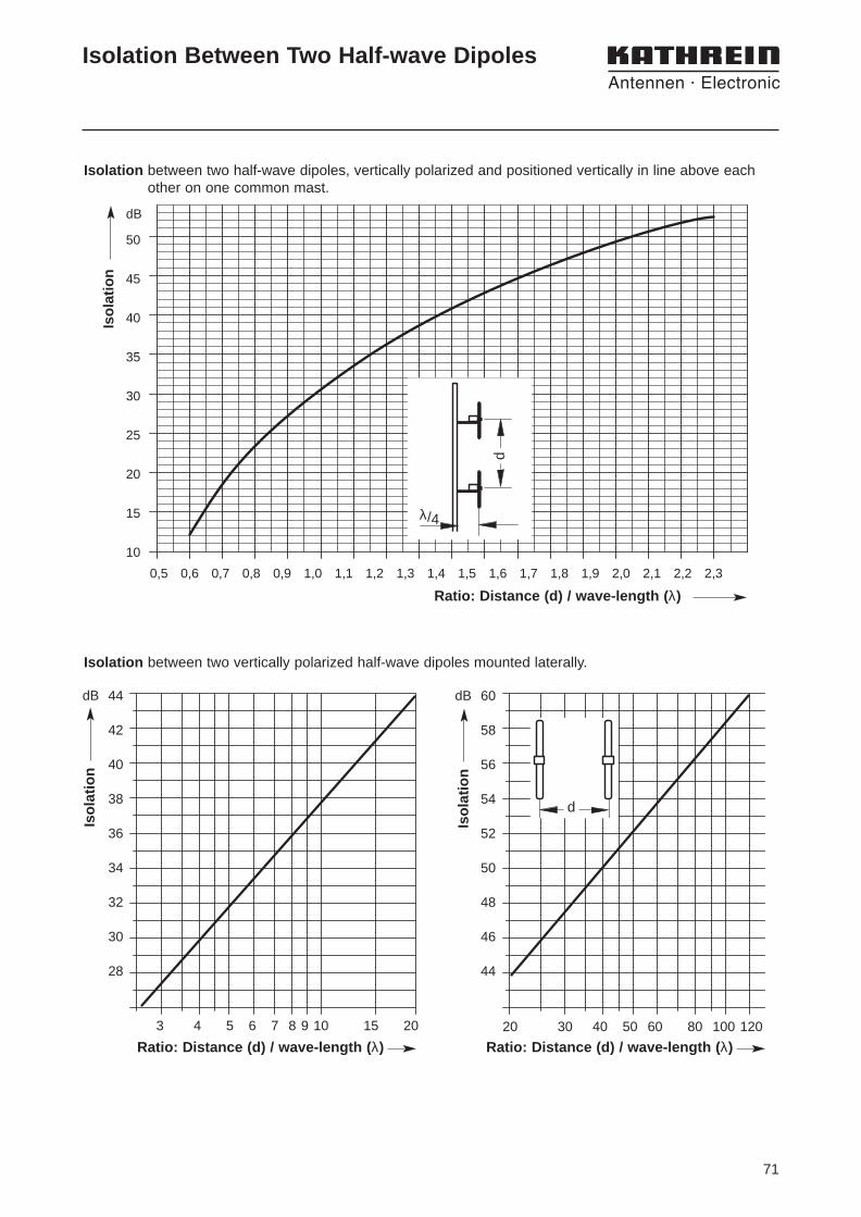
Isolation Between Two Half-wave Dipoles
44
42
40
38
36
34
32
30
28
Kop
peld
ämpf
ung
dB
3 4 5 6 7 8 9 10 15 20
Isolation between two vertically polarized half-wave dipoles mounted laterally.
60
58
56
54
52
50
48
46
44
Kop
peld
ämpf
ung
dB
20 30 40 50 60 80 100 120
50
45
40
35
30
25
20
15
10
Kop
peld
ämpf
ung
dB
0,5 0,6 0,7 0,8 0,9 1,0 1,1 1,2 1,3 1,4 1,5 1,6 1,7 1,8 1,9 2,0 2,1 2,2 2,3
Isolation between two half-wave dipoles, vertically polarized and positioned vertically in line above eachother on one common mast.
λ/4s
s
Isol
atio
n
Ratio: Distance (d) / wave-length ( λ)
Isol
atio
n
Isol
atio
n
d
d
Ratio: Distance (d) / wave-length ( λ) Ratio: Distance (d) / wave-length ( λ)

72
Isolation of Two Vertically Stacked Panels K 73 30 2.
45
40
35
dB
1000 1500 2000
Isolation depends on vertical spacing A (at 450 MHz)
Distance A/mm
Isol
atio
n
A

73
Antenna Gain, VSWR /Reflected power
Antenna Gain in power ratio vs gain in dB
Gain in dB
0 2 4 6 8
Gai
n in
pow
er r
atio
P1
/ P2
8
7
6
5
4
3
2
1
G / dB = 10 log P1P2
Gain in dB
9 10 11 12G
ain
in p
ower
rat
io P
1 / P
2
15
14
13
12
11
10
9
8
Reflection coefficient (r)
1.0
Vol
tage
Sta
ndin
g W
ave
Rat
io (
VS
WR
)
0.1 0.2 0.3 0.4 0.5 0.6 0.8 1.0 2 3 4 5 6 8 10 15 20
1.1
0
1.2
1.3
1.4
1.5
1.6
1.8
2.0
2.5
3.0
0 0.02 0.03 0.045 0.05 0.06 0.07 0.08 0.09 0.1 0.12 0.14 0.16 0.18 0.2 0.3 0.35 0.4
40 30 27 26 24 22 20 18 16 14 12 10 8
Return loss (ar) in dB
P (in %) =Reflected power
Forward power
s-1s+1s = = , r =
ar (in dB) = - 20 log r
P (in %) = (10 r)2 =
P (in %) = . 100
s = VSWR, r = Reflection coefficientar = Return loss
Reflected powerForward power
100100ar/20
10+ P/%10- P/%
1+r1-r
s - 1s + 1
Voltage Standing Wave Ratio (VSWR) vs Reflected power
74
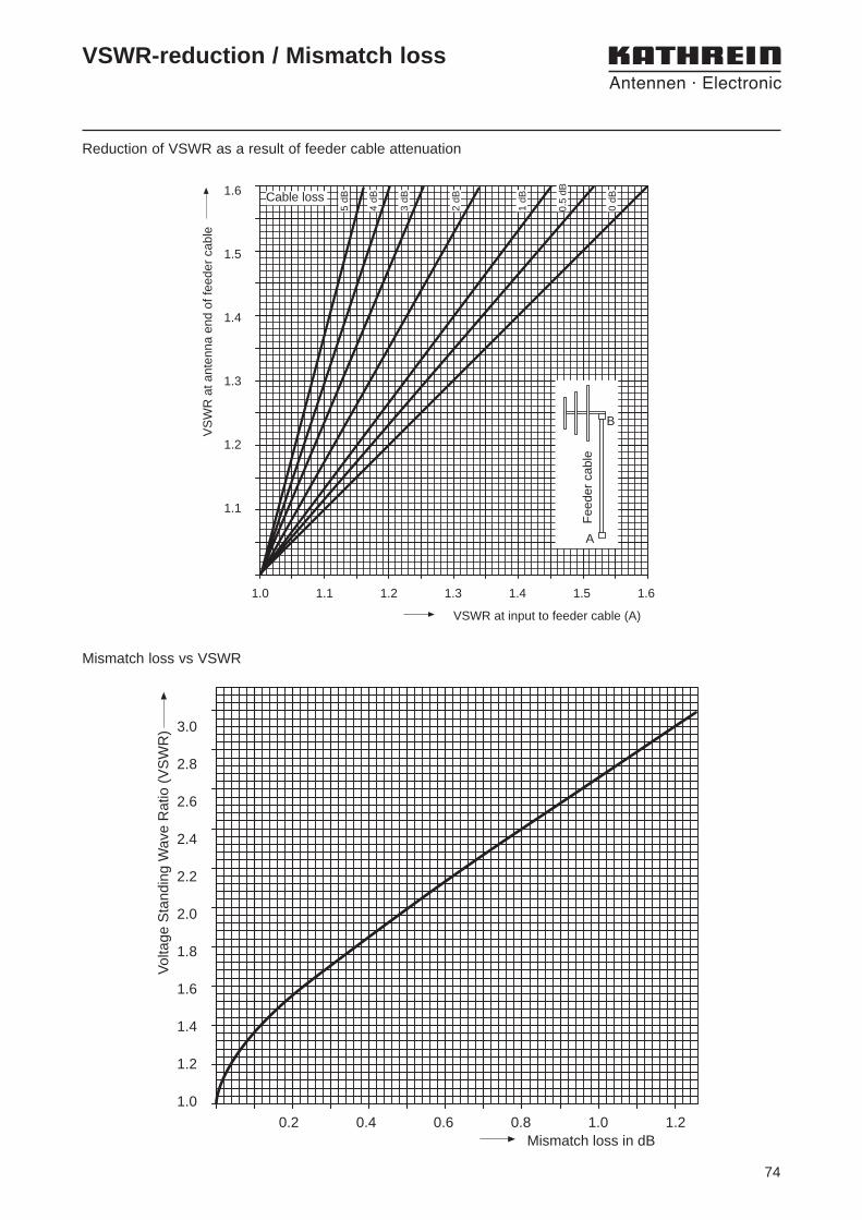
VSWR-reduction / Mismatch loss
Reduction of VSWR as a result of feeder cable attenuation
VSWR at input to feeder cable (A)
VS
WR
at a
nten
na e
nd o
f fee
der
cabl
e1.6
1.5
1.4
1.3
1.2
1.1
1.0 1.1 1.2 1.3 1.4 1.5 1.6F
eede
r ca
ble
A
B
5 dB
4 dB
3 dB
2 dB
1 dB
0.5
dB
0 dBCable loss
Mismatch loss vs VSWR
Mismatch loss in dB
Vol
tage
Sta
ndin
g W
ave
Rat
io (
VS
WR
) 3.0
2.8
2.6
2.4
2.2
2.0
1.8
1.6
1.4
1.2
1.0
0.2 0.4 0.6 0.8 1.0 1.2
75
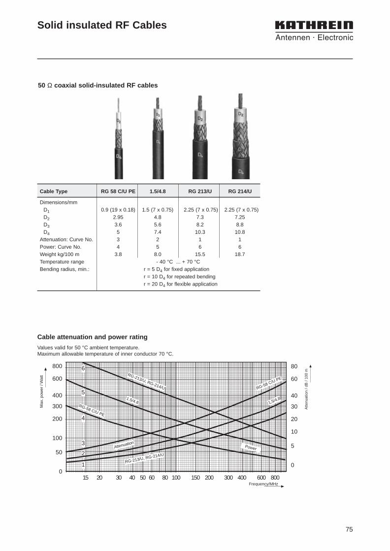
50 Ω coaxial solid-insulated RF cables
Cable Type RG 58 C/U PE 1.5/4.8 RG 213/U RG 214/U
Dimensions/mmD1 0.9 (19 x 0.18) 1.5 (7 x 0.75) 2.25 (7 x 0.75) 2.25 (7 x 0.75)D2 2.95 4.8 7.3 7.25D3 3.6 5.6 8.2 8.8D4 5 7.4 10.3 10.8
Attenuation: Curve No. 3 2 1 1Power: Curve No. 4 5 6 6Weight kg/100 m 3.8 8.0 15.5 18.7Temperature range - 40 °C ... + 70 °CBending radius, min.: r = 5 D4 for fixed application
r = 10 D4 for repeated bendingr = 20 D4 for flexible application
Solid insulated RF Cables
Cable attenuation and power rating
15 20 30 40 50 60 80 100 150 200 300 400 600 800
800
600
400
300
200
100
50
0
80
60
40
30
20
10
5
0
6RG-213/U, RG-214/U RG-58 C/U PE
1.5/4.8 1,5/4,8
RG-58 C/U PE
RG-213/U, RG-214/U
AttenuationPower
5
4
3
2
1
Frequency/MHz
Max
. pow
er /
Wat
t
Atte
nuat
ion
/ dB
/ 10
0 m
Values valid for 50 °C ambient temperature.Maximum allowable temperature of inner conductor 70 °C.
76
D5D4
D2D1
D3
n
A
s
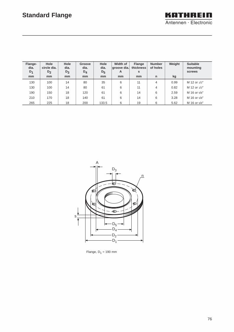
Flange, D1 = 190 mm
Flange- Hole Hole Groove Hole Width of Flange Number Weight Suitabledia. circle dia. dia. dia. dia. groove dia. thickness of holes mountingD1 D2 D3 D4 D5 A s screws
mm mm mm mm mm mm mm n kg
130 100 14 80 35 6 11 4 0.99 M 12 or 1/2″130 100 14 80 61 6 11 4 0.82 M 12 or 1/2″190 150 18 120 61 6 14 6 2.59 M 16 or 5/8″210 170 18 140 61 6 14 6 3.28 M 16 or 5/8″265 225 18 200 133.5 6 19 6 5.62 M 16 or 5/8″
Standard Flange

77

9986
.267
/090
0/2.
5/Z
W/H
AS
ubje
ct t
o al
tera
tion.
KATHREIN-Werke KG . Telephone (++49)8031/184-0 . Fax (++49)8031/184-991Anton-Kathrein-Straße 1 – 3 . P.O. Box 10 04 44 . D-83004 Rosenheim . Germany
Internet: http://www.kathrein.de
Antennen . Electronic
Please contact for:
Sales queries, orders, catalogues or CD-ROM:
Fax: (++49)8031/184-820E-Mail: [email protected]
Technical Information:Fax: (++49)8031/184-973E-Mail: [email protected]