2706-808, dl40 programming software user manual · solid state equipment has operational...
TRANSCRIPT

UserManual
Dataliner DL40Series MessageDisplay OfflineProgrammingSoftware
(Cat. No. 2706-ND1)
Allen-Bradley
Solid state equipment has operational characteristics differing from those ofelectromechanical equipment. “Safety Guidelines for the Application,Installation and Maintenance of Solid State Controls” (Publication SGI-1.1)describes some important differences between solid state equipment andhard–wired electromechanical devices. Because of this difference, and alsobecause of the wide variety of uses for solid state equipment, all personsresponsible for applying this equipment must satisfy themselves that eachintended application of this equipment is acceptable.
In no event will the Allen-Bradley Company be responsible or liable forindirect or consequential damages resulting from the use or application ofthis equipment or software.
The examples and diagrams in this manual are included solely for illustrativepurposes. Because of the many variables and requirements associated withany particular installation, the Allen-Bradley Company cannot assumeresponsibility or liability for actual use based on the examples and diagrams.
No patent liability is assumed by Allen-Bradley Company with respect to useof information, circuits, equipment, or software described in this manual.
Reproduction of the contents of this manual, in whole or in part, withoutwritten permission of the Allen-Bradley Company is prohibited.
Throughout this manual we use notes to make you aware of safetyconsiderations.
!ATTENTION: Identifies information about practices orcircumstances that can lead to personal injury or death, propertydamage, or economic loss.
Attentions help you:
• identify a hazard• avoid the hazard• recognize the consequences
Important: Identifies information that is especially important for successfulapplication and understanding of the product.
Important User Information

Dataliner DL40 Series Message DisplayUser Manual
Table of Contents
i
Chapter 1
What you need to know 1 – 1. . . . . . . . . . . . . . . . . . . . . . . . . . . . . . . . . . . . . . Contents of This Manual 1 – 1. . . . . . . . . . . . . . . . . . . . . . . . . . . . . . . . . . . . . . Conventions Used 1 – 2. . . . . . . . . . . . . . . . . . . . . . . . . . . . . . . . . . . . . . . . . . Related Publications 1 – 3. . . . . . . . . . . . . . . . . . . . . . . . . . . . . . . . . . . . . . . .
Chapter 2
Overview 2 – 1. . . . . . . . . . . . . . . . . . . . . . . . . . . . . . . . . . . . . . . . . . . . . . . . Main Features 2 – 2. . . . . . . . . . . . . . . . . . . . . . . . . . . . . . . . . . . . . . . . . . . . .
Offline Programming Software Option (Catalog Number 2706-ND1) 2 – 2. . . . . PLC-5 Remote I/O PassThrough Via DH+ 2 – 3. . . . . . . . . . . . . . . . . . . . . . . PLC-5E Remote I/O PassThrough Via Ethernet 2 – 4. . . . . . . . . . . . . . . . . . . Support for Extended ASCII Character Set 2 – 4. . . . . . . . . . . . . . . . . . . . . . . Onboard Editor 2 – 5. . . . . . . . . . . . . . . . . . . . . . . . . . . . . . . . . . . . . . . . . . Send ASCII Data to a PLC Via a Remote I/O Link 2 – 5. . . . . . . . . . . . . . . . . . Communications with Any Programmable Controller (Parallel Port Version) 2 – 5Backup Operations 2 – 5. . . . . . . . . . . . . . . . . . . . . . . . . . . . . . . . . . . . . . . Historical Events Stack 2 – 6. . . . . . . . . . . . . . . . . . . . . . . . . . . . . . . . . . . . . Clock Operations 2 – 6. . . . . . . . . . . . . . . . . . . . . . . . . . . . . . . . . . . . . . . . . RS-232 and RS-485 Ports 2 – 6. . . . . . . . . . . . . . . . . . . . . . . . . . . . . . . . . . Debug Mode (Parallel Port Version) 2 – 6. . . . . . . . . . . . . . . . . . . . . . . . . . . . Auxiliary Devices 2 – 7. . . . . . . . . . . . . . . . . . . . . . . . . . . . . . . . . . . . . . . . . Background Messages 2 – 7. . . . . . . . . . . . . . . . . . . . . . . . . . . . . . . . . . . . . Hidden Messages 2 – 7. . . . . . . . . . . . . . . . . . . . . . . . . . . . . . . . . . . . . . . . Embedded Variables 2 – 7. . . . . . . . . . . . . . . . . . . . . . . . . . . . . . . . . . . . . . Data Mode Selection 2 – 8. . . . . . . . . . . . . . . . . . . . . . . . . . . . . . . . . . . . . . Message Chaining 2 – 8. . . . . . . . . . . . . . . . . . . . . . . . . . . . . . . . . . . . . . . . Adjustable Parameters for Serial Communications 2 – 8. . . . . . . . . . . . . . . . .
Operating Modes 2 – 9. . . . . . . . . . . . . . . . . . . . . . . . . . . . . . . . . . . . . . . . . . . Run Mode 2 – 9. . . . . . . . . . . . . . . . . . . . . . . . . . . . . . . . . . . . . . . . . . . . . . Other Operating Modes 2 – 11. . . . . . . . . . . . . . . . . . . . . . . . . . . . . . . . . . . .
Special Messages 2 – 12. . . . . . . . . . . . . . . . . . . . . . . . . . . . . . . . . . . . . . . . . . System Requirements for Remote I/O Without PassThrough File Transfers 2 – 12. System Requirements for Remote I/O PassThrough Using DH+ 2 – 13. . . . . . . . . System Requirements for Remote I/O PassThrough Using Ethernet 2 – 13. . . . . . Catalog Numbers 2 – 14. . . . . . . . . . . . . . . . . . . . . . . . . . . . . . . . . . . . . . . . . . . Compatible Keyboards 2 – 14. . . . . . . . . . . . . . . . . . . . . . . . . . . . . . . . . . . . . . . Options & Accessories 2 – 15. . . . . . . . . . . . . . . . . . . . . . . . . . . . . . . . . . . . . . .
Overview
Introduction to the DL40
Dataliner DL40 Series Message DisplayUser Manual
Table of Contents
ii
Chapter 3
Personal Computer Requirements 3 – 1. . . . . . . . . . . . . . . . . . . . . . . . . . . . . . . Package Contents 3 – 1. . . . . . . . . . . . . . . . . . . . . . . . . . . . . . . . . . . . . . . . . . Memory Requirements 3 – 1. . . . . . . . . . . . . . . . . . . . . . . . . . . . . . . . . . . . . . . Memory Management 3 – 2. . . . . . . . . . . . . . . . . . . . . . . . . . . . . . . . . . . . . . . Installation 3 – 3. . . . . . . . . . . . . . . . . . . . . . . . . . . . . . . . . . . . . . . . . . . . . . . Basic Installation
(Without PassThrough file transfers) 3 – 3. . . . . . . . . . . . . . . . . . . . . . . . . . Installing the Software for DH+ PLC PassThrough 3 – 4. . . . . . . . . . . . . . . . . . .
Install and Configure Your DH+ Communication Interface Card 3 – 4. . . . . . . . Install the Offline Programming Software 3 – 4. . . . . . . . . . . . . . . . . . . . . . . . Install and Configure INTERCHANGE 3 – 4. . . . . . . . . . . . . . . . . . . . . . . . . . Create CFG_KT.INI File 3 – 6. . . . . . . . . . . . . . . . . . . . . . . . . . . . . . . . . . . .
Installing the Software for Ethernet PLC PassThrough 3 – 9. . . . . . . . . . . . . . . . Install Ethernet Card 3 – 9. . . . . . . . . . . . . . . . . . . . . . . . . . . . . . . . . . . . . . Install the PC/TCP Software 3 – 9. . . . . . . . . . . . . . . . . . . . . . . . . . . . . . . . . Install the Offline Programming Software 3 – 9. . . . . . . . . . . . . . . . . . . . . . . . Modify CONFIG.SYS & AUTOEXEC.BAT Files 3 – 10. . . . . . . . . . . . . . . . . . . Restart Your PC 3 – 10. . . . . . . . . . . . . . . . . . . . . . . . . . . . . . . . . . . . . . . . . . Configure Your PLC 3 – 11. . . . . . . . . . . . . . . . . . . . . . . . . . . . . . . . . . . . . . .
Starting the Program 3 – 11. . . . . . . . . . . . . . . . . . . . . . . . . . . . . . . . . . . . . . . . Establishing Initial Communications In Non-Networked Installations 3 – 11. . . . . . .
Chapter 4
Starting the Program 4 – 1. . . . . . . . . . . . . . . . . . . . . . . . . . . . . . . . . . . . . . . . Title Screen & Main Menu Bar 4 – 2. . . . . . . . . . . . . . . . . . . . . . . . . . . . . . . . . Getting Help 4 – 3. . . . . . . . . . . . . . . . . . . . . . . . . . . . . . . . . . . . . . . . . . . . . . The Setup Menu 4 – 4. . . . . . . . . . . . . . . . . . . . . . . . . . . . . . . . . . . . . . . . . . .
Configuring the Program to Match Your Monitor 4 – 5. . . . . . . . . . . . . . . . . . . Setting Time & Date 4 – 6. . . . . . . . . . . . . . . . . . . . . . . . . . . . . . . . . . . . . . .
Menu Key Control 4 – 7. . . . . . . . . . . . . . . . . . . . . . . . . . . . . . . . . . . . . . . . . . Shortcut Keys 4 – 7. . . . . . . . . . . . . . . . . . . . . . . . . . . . . . . . . . . . . . . . . . . . . Exiting the Program 4 – 8. . . . . . . . . . . . . . . . . . . . . . . . . . . . . . . . . . . . . . . . .
Chapter 5
Develop Menu Top Level 5 – 1. . . . . . . . . . . . . . . . . . . . . . . . . . . . . . . . . . . . . Special keys 5 – 2. . . . . . . . . . . . . . . . . . . . . . . . . . . . . . . . . . . . . . . . . . . . Notes 5 – 2. . . . . . . . . . . . . . . . . . . . . . . . . . . . . . . . . . . . . . . . . . . . . . . . .
File Selections Screen 5 – 3. . . . . . . . . . . . . . . . . . . . . . . . . . . . . . . . . . . . . . . Special keys 5 – 3. . . . . . . . . . . . . . . . . . . . . . . . . . . . . . . . . . . . . . . . . . . .
Installing the Software
Navigating the Software
The Develop Menu

Dataliner DL40 Series Message DisplayUser Manual
Table of Contents
iii
Notes 5 – 4. . . . . . . . . . . . . . . . . . . . . . . . . . . . . . . . . . . . . . . . . . . . . . . . . Create New File Pop-up Window 5 – 4. . . . . . . . . . . . . . . . . . . . . . . . . . . . . . . .
Special keys 5 – 4. . . . . . . . . . . . . . . . . . . . . . . . . . . . . . . . . . . . . . . . . . . . Notes 5 – 5. . . . . . . . . . . . . . . . . . . . . . . . . . . . . . . . . . . . . . . . . . . . . . . . .
Data Path Directory Pop-up Window 5 – 5. . . . . . . . . . . . . . . . . . . . . . . . . . . . . Special keys 5 – 6. . . . . . . . . . . . . . . . . . . . . . . . . . . . . . . . . . . . . . . . . . . . Notes 5 – 6. . . . . . . . . . . . . . . . . . . . . . . . . . . . . . . . . . . . . . . . . . . . . . . . .
Develop Screen Menu Bar 5 – 6. . . . . . . . . . . . . . . . . . . . . . . . . . . . . . . . . . . . Special keys 5 – 7. . . . . . . . . . . . . . . . . . . . . . . . . . . . . . . . . . . . . . . . . . . . Notes 5 – 7. . . . . . . . . . . . . . . . . . . . . . . . . . . . . . . . . . . . . . . . . . . . . . . . .
Messages Menu 5 – 8. . . . . . . . . . . . . . . . . . . . . . . . . . . . . . . . . . . . . . . . . . . Special keys 5 – 9. . . . . . . . . . . . . . . . . . . . . . . . . . . . . . . . . . . . . . . . . . . .
Edit Message Screen 5 – 9. . . . . . . . . . . . . . . . . . . . . . . . . . . . . . . . . . . . . . . . Special keys 5 – 10. . . . . . . . . . . . . . . . . . . . . . . . . . . . . . . . . . . . . . . . . . . .
Message Text Window 5 – 10. . . . . . . . . . . . . . . . . . . . . . . . . . . . . . . . . . . . . . . Special keys and Editing Rules 5 – 11. . . . . . . . . . . . . . . . . . . . . . . . . . . . . . . More about variables 5 – 12. . . . . . . . . . . . . . . . . . . . . . . . . . . . . . . . . . . . . .
Insert Formatted Variable With [CTRL][V] 5 – 12. . . . . . . . . . . . . . . . . . . . . . Change Formatted Variable With [CTRL][F] 5 – 12. . . . . . . . . . . . . . . . . . . . Insert ASCII or BCD Variable With [CTRL][W] 5 – 13. . . . . . . . . . . . . . . . . . . Insert Request for ASCII Input Data With [CTRL][X] 5 – 13. . . . . . . . . . . . . . Insert Time Into a Message With [CTRL][T] 5 – 14. . . . . . . . . . . . . . . . . . . . Insert Date Into a Message With [CTRL][Y] 5 – 14. . . . . . . . . . . . . . . . . . . .
Notes 5 – 14. . . . . . . . . . . . . . . . . . . . . . . . . . . . . . . . . . . . . . . . . . . . . . . . . Create New Message 5 – 15. . . . . . . . . . . . . . . . . . . . . . . . . . . . . . . . . . . . . . .
Notes 5 – 15. . . . . . . . . . . . . . . . . . . . . . . . . . . . . . . . . . . . . . . . . . . . . . . . . Copy (Messages) Screen 5 – 16. . . . . . . . . . . . . . . . . . . . . . . . . . . . . . . . . . . . .
Special keys 5 – 17. . . . . . . . . . . . . . . . . . . . . . . . . . . . . . . . . . . . . . . . . . . . Notes 5 – 17. . . . . . . . . . . . . . . . . . . . . . . . . . . . . . . . . . . . . . . . . . . . . . . . .
Delete (Message) Screen 5 – 18. . . . . . . . . . . . . . . . . . . . . . . . . . . . . . . . . . . . . Special keys 5 – 19. . . . . . . . . . . . . . . . . . . . . . . . . . . . . . . . . . . . . . . . . . . . Notes 5 – 19. . . . . . . . . . . . . . . . . . . . . . . . . . . . . . . . . . . . . . . . . . . . . . . . .
Renumber (Messages) Screen 5 – 19. . . . . . . . . . . . . . . . . . . . . . . . . . . . . . . . . Notes 5 – 20. . . . . . . . . . . . . . . . . . . . . . . . . . . . . . . . . . . . . . . . . . . . . . . . .
Text Search Screen 5 – 21. . . . . . . . . . . . . . . . . . . . . . . . . . . . . . . . . . . . . . . . . Special keys and Editing Rules 5 – 22. . . . . . . . . . . . . . . . . . . . . . . . . . . . . . .
Modify Message Attributes Screen 5 – 23. . . . . . . . . . . . . . . . . . . . . . . . . . . . . . Special keys 5 – 24. . . . . . . . . . . . . . . . . . . . . . . . . . . . . . . . . . . . . . . . . . . . More about Attributes 5 – 25. . . . . . . . . . . . . . . . . . . . . . . . . . . . . . . . . . . . . .
Display message on what line 5 – 25. . . . . . . . . . . . . . . . . . . . . . . . . . . . . . Scroll message 5 – 25. . . . . . . . . . . . . . . . . . . . . . . . . . . . . . . . . . . . . . . . Print message 5 – 25. . . . . . . . . . . . . . . . . . . . . . . . . . . . . . . . . . . . . . . . . Send message to Slave (address) number 5 – 26. . . . . . . . . . . . . . . . . . . . . Wait time for message 5 – 26. . . . . . . . . . . . . . . . . . . . . . . . . . . . . . . . . . . Clear message automatically 5 – 26. . . . . . . . . . . . . . . . . . . . . . . . . . . . . .

Dataliner DL40 Series Message DisplayUser Manual
Table of Contents
iv
Repeat message automatically 5 – 27. . . . . . . . . . . . . . . . . . . . . . . . . . . . . Chain message to another 5 – 27. . . . . . . . . . . . . . . . . . . . . . . . . . . . . . . . Energize relay 5 – 27. . . . . . . . . . . . . . . . . . . . . . . . . . . . . . . . . . . . . . . . . Send message to the stack 5 – 28. . . . . . . . . . . . . . . . . . . . . . . . . . . . . . . . Send message time to the stack 5 – 28. . . . . . . . . . . . . . . . . . . . . . . . . . . . Hide message on display 5 – 28. . . . . . . . . . . . . . . . . . . . . . . . . . . . . . . . . Acknowledge message 5 – 29. . . . . . . . . . . . . . . . . . . . . . . . . . . . . . . . . . Slave message color 5 – 29. . . . . . . . . . . . . . . . . . . . . . . . . . . . . . . . . . . . Slave message length 5 – 29. . . . . . . . . . . . . . . . . . . . . . . . . . . . . . . . . . . Echo relay to slave 5 – 30. . . . . . . . . . . . . . . . . . . . . . . . . . . . . . . . . . . . .
Notes 5 – 30. . . . . . . . . . . . . . . . . . . . . . . . . . . . . . . . . . . . . . . . . . . . . . . . . Message Attribute Default Screen 5 – 31. . . . . . . . . . . . . . . . . . . . . . . . . . . . . . .
Special keys 5 – 32. . . . . . . . . . . . . . . . . . . . . . . . . . . . . . . . . . . . . . . . . . . . Notes 5 – 32. . . . . . . . . . . . . . . . . . . . . . . . . . . . . . . . . . . . . . . . . . . . . . . . .
Options Menu 5 – 32. . . . . . . . . . . . . . . . . . . . . . . . . . . . . . . . . . . . . . . . . . . . . Special keys 5 – 34. . . . . . . . . . . . . . . . . . . . . . . . . . . . . . . . . . . . . . . . . . . .
Ports Menu 5 – 35. . . . . . . . . . . . . . . . . . . . . . . . . . . . . . . . . . . . . . . . . . . . . . . Special keys 5 – 35. . . . . . . . . . . . . . . . . . . . . . . . . . . . . . . . . . . . . . . . . . . . Notes 5 – 36. . . . . . . . . . . . . . . . . . . . . . . . . . . . . . . . . . . . . . . . . . . . . . . . .
RS-232 Port Settings 5 – 36. . . . . . . . . . . . . . . . . . . . . . . . . . . . . . . . . . . . RS-485 Port Settings 5 – 36. . . . . . . . . . . . . . . . . . . . . . . . . . . . . . . . . . . . RS-232 Printer Settings 5 – 36. . . . . . . . . . . . . . . . . . . . . . . . . . . . . . . . . . RS-232 Tape Recorder Settings 5 – 37. . . . . . . . . . . . . . . . . . . . . . . . . . . . Triggering Port Settings 5 – 37. . . . . . . . . . . . . . . . . . . . . . . . . . . . . . . . . .
Verify Menu 5 – 38. . . . . . . . . . . . . . . . . . . . . . . . . . . . . . . . . . . . . . . . . . . . . . . Special keys 5 – 39. . . . . . . . . . . . . . . . . . . . . . . . . . . . . . . . . . . . . . . . . . . . Communications via RS–485 5 – 40. . . . . . . . . . . . . . . . . . . . . . . . . . . . . . . . Communications via RS–232 5 – 41. . . . . . . . . . . . . . . . . . . . . . . . . . . . . . . . Message text window 5 – 42. . . . . . . . . . . . . . . . . . . . . . . . . . . . . . . . . . . . . .
Device 5 – 42. . . . . . . . . . . . . . . . . . . . . . . . . . . . . . . . . . . . . . . . . . . . . . . . . . Special keys 5 – 43. . . . . . . . . . . . . . . . . . . . . . . . . . . . . . . . . . . . . . . . . . . .
Chapter 6
Transfer Menu Top Level 6 – 1. . . . . . . . . . . . . . . . . . . . . . . . . . . . . . . . . . . . . Special keys 6 – 2. . . . . . . . . . . . . . . . . . . . . . . . . . . . . . . . . . . . . . . . . . . . Notes 6 – 2. . . . . . . . . . . . . . . . . . . . . . . . . . . . . . . . . . . . . . . . . . . . . . . . .
Downloading a File Via RS-232 or RS-485 6 – 3. . . . . . . . . . . . . . . . . . . . . . . . . Uploading a File Via RS-232 or RS-485 6 – 7. . . . . . . . . . . . . . . . . . . . . . . . . . . Downloading a File Via Remote I/O (PassThrough) 6 – 9. . . . . . . . . . . . . . . . . . Uploading a File Via Remote I/O (PassThrough) 6 – 12. . . . . . . . . . . . . . . . . . . . . Creating a New Communications File 6 – 13. . . . . . . . . . . . . . . . . . . . . . . . . . . .
Selecting a Hardware Device 6 – 15. . . . . . . . . . . . . . . . . . . . . . . . . . . . . . . . Setting Device Parameters for a DH+ Network 6 – 16. . . . . . . . . . . . . . . . . . . .
The Transfer Menu

Dataliner DL40 Series Message DisplayUser Manual
Table of Contents
v
DH+ Connection Type 6 – 16. . . . . . . . . . . . . . . . . . . . . . . . . . . . . . . . . . . DH+ Network Access 6 – 17. . . . . . . . . . . . . . . . . . . . . . . . . . . . . . . . . . . .
Setting Device Parameters for an Ethernet Network 6 – 17. . . . . . . . . . . . . . . . Routing 6 – 18. . . . . . . . . . . . . . . . . . . . . . . . . . . . . . . . . . . . . . . . . . . . . . Pushwheel 6 – 18. . . . . . . . . . . . . . . . . . . . . . . . . . . . . . . . . . . . . . . . . . . Channel 6 – 18. . . . . . . . . . . . . . . . . . . . . . . . . . . . . . . . . . . . . . . . . . . . .
Modifying an Existing Communications File 6 – 19. . . . . . . . . . . . . . . . . . . . . . . . Sending the Time and Date to a DL40 Via RS-232 or RS-485 6 – 19. . . . . . . . . . . Writing a File to Tape 6 – 20. . . . . . . . . . . . . . . . . . . . . . . . . . . . . . . . . . . . . . . . Reading a File from Tape 6 – 23. . . . . . . . . . . . . . . . . . . . . . . . . . . . . . . . . . . . .
Chapter 7
Reports Menu 7 – 1. . . . . . . . . . . . . . . . . . . . . . . . . . . . . . . . . . . . . . . . . . . . . Special keys 7 – 2. . . . . . . . . . . . . . . . . . . . . . . . . . . . . . . . . . . . . . . . . . . . Notes 7 – 2. . . . . . . . . . . . . . . . . . . . . . . . . . . . . . . . . . . . . . . . . . . . . . . . .
Select File Submenu 7 – 2. . . . . . . . . . . . . . . . . . . . . . . . . . . . . . . . . . . . . . . . Configure Ports Submenu 7 – 3. . . . . . . . . . . . . . . . . . . . . . . . . . . . . . . . . . . . Starting the Print Job 7 – 4. . . . . . . . . . . . . . . . . . . . . . . . . . . . . . . . . . . . . . . .
Chapter 8
Files Menu Top Level 8 – 1. . . . . . . . . . . . . . . . . . . . . . . . . . . . . . . . . . . . . . . . Special keys 8 – 2. . . . . . . . . . . . . . . . . . . . . . . . . . . . . . . . . . . . . . . . . . . .
Select Files Menu 8 – 3. . . . . . . . . . . . . . . . . . . . . . . . . . . . . . . . . . . . . . . . . . File Selections/File Picks Window 8 – 4. . . . . . . . . . . . . . . . . . . . . . . . . . . . . . . Copy File(s) 8 – 5. . . . . . . . . . . . . . . . . . . . . . . . . . . . . . . . . . . . . . . . . . . . . .
Copying single files 8 – 5. . . . . . . . . . . . . . . . . . . . . . . . . . . . . . . . . . . . . . . Copying multiple files 8 – 6. . . . . . . . . . . . . . . . . . . . . . . . . . . . . . . . . . . . . .
Delete File(s) 8 – 6. . . . . . . . . . . . . . . . . . . . . . . . . . . . . . . . . . . . . . . . . . . . . . Rename File(s) 8 – 7. . . . . . . . . . . . . . . . . . . . . . . . . . . . . . . . . . . . . . . . . . . .
Renaming or moving single files 8 – 7. . . . . . . . . . . . . . . . . . . . . . . . . . . . . . Moving multiple files 8 – 8. . . . . . . . . . . . . . . . . . . . . . . . . . . . . . . . . . . . . . .
Convert DL20 File(s) 8 – 8. . . . . . . . . . . . . . . . . . . . . . . . . . . . . . . . . . . . . . . . Converting single files 8 – 8. . . . . . . . . . . . . . . . . . . . . . . . . . . . . . . . . . . . . Converting multiple files 8 – 9. . . . . . . . . . . . . . . . . . . . . . . . . . . . . . . . . . . .
Appendix A
Using the Worksheets A – 1. . . . . . . . . . . . . . . . . . . . . . . . . . . . . . . . . . . . . . . Two Line Worksheet A – 1. . . . . . . . . . . . . . . . . . . . . . . . . . . . . . . . . . . . . . . . Four Line Worksheet A – 2. . . . . . . . . . . . . . . . . . . . . . . . . . . . . . . . . . . . . . . .
The Reports Menu
The Files Menu
Message Display Worksheets

Dataliner DL40 Series Message DisplayUser Manual
Table of Contents
vi
Appendix B
2706-NC12 B – 1. . . . . . . . . . . . . . . . . . . . . . . . . . . . . . . . . . . . . . . . . . . . . . . 2706-NC13 B – 1. . . . . . . . . . . . . . . . . . . . . . . . . . . . . . . . . . . . . . . . . . . . . . . 2706-NC14 B – 2. . . . . . . . . . . . . . . . . . . . . . . . . . . . . . . . . . . . . . . . . . . . . . . 2706-NC15 B – 2. . . . . . . . . . . . . . . . . . . . . . . . . . . . . . . . . . . . . . . . . . . . . . . DL40 to Allen-Bradley 1770-SA or -SB Tape Recorder B – 3. . . . . . . . . . . . . . . .
Appendix C
Standard ASCII Character Set C – 1. . . . . . . . . . . . . . . . . . . . . . . . . . . . . . . . . Extended ASCII Character Set C – 2. . . . . . . . . . . . . . . . . . . . . . . . . . . . . . . . .
Cables
ASCII Character Sets

Chapter
1Chapter 1Overview
Figure 1Table 1
1 – 1
Chapter 1
Overview
This chapter provides an overview of the Dataliner DL40 Series MessageDisplay Offline Programming Software User Manual. The topics it coversinclude:
• What you need to know
• Contents of the manual
• Conventions used throughout the manual
• Related publications
No special knowledge is required to read this manual or use the DL40Offline Programming Software (Catalog No. 2706-ND1). However, youshould be familiar with the operation of the DL40 and how it will beintegrated into your control system before trying to use the OfflineProgramming Software.
This manual provides the information necessary to use the DL40 OfflineProgramming Software. Refer to Table 1.A for a summary of this manual’scontents.
What you need to know
Contents of This Manual

Chapter 1Overview
1 – 2
Table 1.AManual Contents
Chapter Title Purpose
1 Overview Provides an overview of the manual.
2 Introduction to the DL40 Provides an overview of the DL40 Message Display
3 Installing the SoftwareDescribes how to install the DL40 OfflineProgramming Software for a variety ofenvironments
4 Navigating the Software
Provides a description of the overall design of thesoftware, including a summary of all menus. Alsoincludes instructions for setting up and exiting thesoftware.
5 The Develop Menu Describes the contents and use of the Developmenu
6 The Transfer Menu Describes the contents and use of the Transfermenu
7 The Reports Menu Describes the contents and use of the Reportsmenu
8 The Files Menu Describes the contents and use of the Files menu
A Message DisplayWorksheets Convenient forms for recording message contents
B Cables Cable pinout diagrams
C ASCII Character Set Summary of ASCII characters and their keyboardcodes
Index
The following conventions are used in this manual:
• All menus and screens reproduced in this manual are approximaterenderings of what you will see on your terminal screen. Allen-Bradleyreserves the right to make minor modifications to any menu or screen tohelp improve performance.
• A symbol or word in brackets represents a single key that you press.These include keys such as [A] or [Del] . Since the Dataliner can beprogrammed with a variety of keyboards or terminals, the printing onyour keyboard may be different from the symbol or word indicated inbrackets. This manual uses ↵ to specify the carriage return function of akeyboard. On your keyboard this may correspond to an [ENTER] , ↵ , or[Rtrn] key.
• The up caret, ^ , is the symbol for a control character. Example: ^W is thesymbol for a Control W character. On most computers this character isentered by pressing [Ctrl] and [W] simultaneously.
• In the following chapters we will refer to the Dataliner DL40 SeriesMessage Display as the DL40.
Conventions Used

Chapter 1Overview
1 – 3
Other publications to which you may want to refer include:
• Dataliner DL40 Series Message Display User Manual (Publication2706–807)
• Keyboard Interface Reader User Manual (Publication 2755-824)
• Keyboard Interface Readers for Bar Code Data Entry ProgrammingGuide (Publication 2755-824.1)
Related Publications
Chapter
2Chapter 2Introduction to the DL40
Figure 2Table 2
2 – 1
Chapter 2
Introduction to the DL40
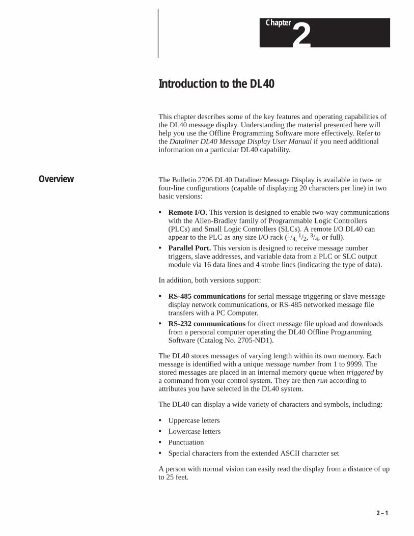
This chapter describes some of the key features and operating capabilities ofthe DL40 message display. Understanding the material presented here willhelp you use the Offline Programming Software more effectively. Refer tothe Dataliner DL40 Message Display User Manual if you need additionalinformation on a particular DL40 capability.
The Bulletin 2706 DL40 Dataliner Message Display is available in two- orfour-line configurations (capable of displaying 20 characters per line) in twobasic versions:
• Remote I/O. This version is designed to enable two-way communicationswith the Allen-Bradley family of Programmable Logic Controllers(PLCs) and Small Logic Controllers (SLCs). A remote I/O DL40 canappear to the PLC as any size I/O rack (1/4,
1/2, 3/4, or full).
• Parallel Port. This version is designed to receive message numbertriggers, slave addresses, and variable data from a PLC or SLC outputmodule via 16 data lines and 4 strobe lines (indicating the type of data).
In addition, both versions support:
• RS-485 communications for serial message triggering or slave messagedisplay network communications, or RS-485 networked message filetransfers with a PC Computer.
• RS-232 communications for direct message file upload and downloadsfrom a personal computer operating the DL40 Offline ProgrammingSoftware (Catalog No. 2705-ND1).
The DL40 stores messages of varying length within its own memory. Eachmessage is identified with a unique message number from 1 to 9999. Thestored messages are placed in an internal memory queue when triggered bya command from your control system. They are then run according toattributes you have selected in the DL40 system.
The DL40 can display a wide variety of characters and symbols, including:
• Uppercase letters
• Lowercase letters
• Punctuation
• Special characters from the extended ASCII character set
A person with normal vision can easily read the display from a distance of upto 25 feet.
Overview

Chapter 2Introduction to the DL40
2 – 2
The DL40 message display is a versatile tool that comes equipped with a fullrange of high-end programming and performance features. A summary ofthose features appears below.
Table 2.ASummary of DL40 capabilities
Capability Remote I/OVersion
Parallel PortVersion
Supports offline programming software Yes Yes
PLC-5 Remote I/O PassThrough via DH+ Yes No
PLC-5E Remote I/O PassThrough via Ethernet Yes No
Extended ASCII character set support Yes Yes
Onboard editor Yes Yes
Send ASCII data to a PLC via a Remote I/O link Yes No
Send ASCII data to a device via an RS-485 link Yes Yes
Communications with any programmable controller No Yes
Backup operations Yes Yes
Customizable historical events stack Yes Yes
Clock operations Yes Yes
RS-232 and RS-485 ports Yes Yes
Debug Mode No Yes
Support for auxiliary devices such as slave displays andprinters
Yes Yes
Background messages Yes Yes
Hidden messages Yes Yes
Embedded variables Yes Yes
Data mode selection Yes Yes
Message chaining Yes Yes
Adjustable parameters for serial communications Yes Yes
Offline Programming Software Option (Catalog Number 2706-ND1)
You can easily and quickly create and edit application files using this offlineprogramming utility. You can use its interactive menus on a personalcomputer to create messages, set message attributes, and download to one ormore DL40 message displays.
Main Features
Chapter 2Introduction to the DL40
2 – 3
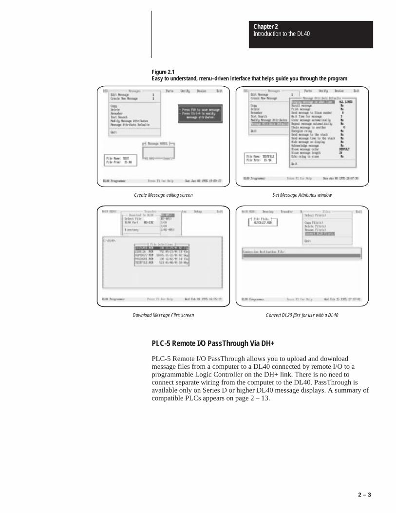
Figure 2.1Easy to understand, menu–driven interface that helps guide you through the program
Create Message editing screen Set Message Attributes window
Convert DL20 files for use with a DL40Download Message Files screen
PLC-5 Remote I/O PassThrough Via DH+
PLC-5 Remote I/O PassThrough allows you to upload and downloadmessage files from a computer to a DL40 connected by remote I/O to aprogrammable Logic Controller on the DH+ link. There is no need toconnect separate wiring from the computer to the DL40. PassThrough isavailable only on Series D or higher DL40 message displays. A summary ofcompatible PLCs appears on page 2 – 13.
Chapter 2Introduction to the DL40
2 – 4
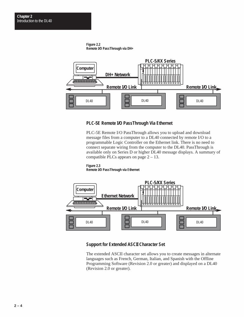
Figure 2.2Remote I/O PassThrough via DH+
ComputerDH+ Network
DL40
Remote I/O Link
DL40DL40
Remote I/O Link
PLC-5/XX Series
PLC-5E Remote I/O PassThrough Via Ethernet
PLC-5E Remote I/O PassThrough allows you to upload and downloadmessage files from a computer to a DL40 connected by remote I/O to aprogrammable Logic Controller on the Ethernet link. There is no need toconnect separate wiring from the computer to the DL40. PassThrough isavailable only on Series D or higher DL40 message displays. A summary ofcompatible PLCs appears on page 2 – 13.
Figure 2.3Remote I/O PassThrough via Ethernet
ComputerEthernet Network
DL40
Remote I/O Link
DL40DL40
Remote I/O Link
PLC-5/XX Series
Support for Extended ASCII Character Set
The extended ASCII character set allows you to create messages in alternatelanguages such as French, German, Italian, and Spanish with the OfflineProgramming Software (Revision 2.0 or greater) and displayed on a DL40(Revision 2.0 or greater).
Chapter 2Introduction to the DL40
2 – 5
Onboard Editor
The onboard editor lets you create or edit messages, select messageattributes, and set options and variable formats on a Version 2.XX or laterDL40 message display using any of a number of standard keyboards.
Send ASCII Data to a PLC Via a Remote I/O Link
Using Remote I/O communications, you can send ASCII data to your PLC.Simply attach an IBM compatible keyboard to the DL40 message display,and you can enter parts numbers, badge numbers, and similar information asrequired. The DL40 processes and displays the information, and then sends iton to the controller.
You can enter bar code data using a wedge attached to an Allen-Bradley barcode scanner. The DL40 displays scanned bar code information, then sendsthe data to the PLC through the Remote I/O. Refer to Publications 2755-824and 2755-824.1 for information on applications using Allen-Bradley wedges.
You can establish similar communications over an RS-485 link.
Communications with Any Programmable Controller (Parallel PortVersion)
The DL40 can accept information from any programmable controller over atotal of 20 input lines (16 data and 4 strobe lines).
Parallel Port versions of the DL40 also have a 12 VDC terminal that can beused to power outputs that pull data and strobe lines high.
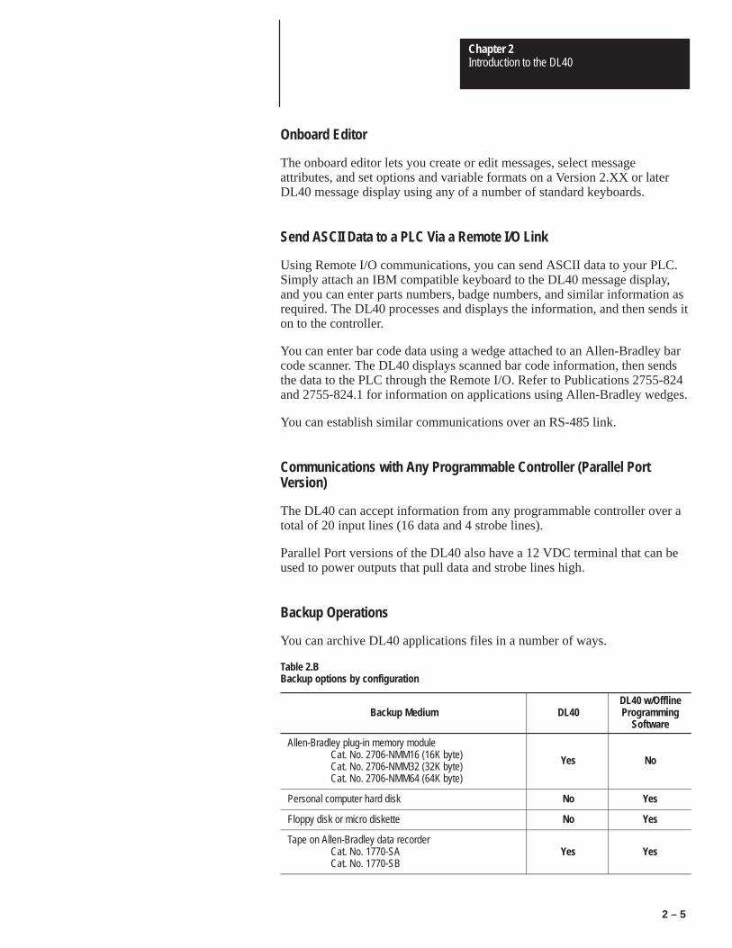
Backup Operations
You can archive DL40 applications files in a number of ways.
Table 2.BBackup options by configuration
Backup Medium DL40DL40 w/OfflineProgramming
Software
Allen-Bradley plug-in memory moduleCat. No. 2706-NMM16 (16K byte)Cat. No. 2706-NMM32 (32K byte)Cat. No. 2706-NMM64 (64K byte)
Yes No
Personal computer hard disk No Yes
Floppy disk or micro diskette No Yes
Tape on Allen-Bradley data recorderCat. No. 1770-SACat. No. 1770-SB
Yes Yes
Chapter 2Introduction to the DL40
2 – 6
Historical Events Stack
With the DL40’s Historical Events Stack you can record the occurrence andsequence of some or all of the messages or variable data values that havebeen triggered and/or displayed. The 16K bytes of memory available for thisrecord will hold about 1,000 events. You can view this record on the DL40itself, or obtain a printout for offline reference.
Clock Operations
The DL40 contains a real-time battery-backed clock that will keep accuratetime even when power is removed from the unit. The DL40 can display thecurrent time and/or date in either AM/PM or 24-hour military format.
Date and time information can be displayed as part of any triggered message,and passed on to a PLC. You can also date- or time-stamp events as they arerecorded in the Historical Events Stack.
You can set the DL40 internal clock from the front panel menus, from a PLC,or through the Offline Programming Software.
RS-232 and RS-485 Ports
The DL40 has both an RS-232 and RS-485 port.
The RS-232 port can be used to:
• upload or download message files from a computer
• print messages and/or Historical Event Stack contents
• upload or download message files using a data (tape) recorder
The RS-485 port can be used to:
• trigger messages with or without variable data content
• multi-drop upload or download message files from a personal computer
• send messages to slave message displays
• send ASCII data entered via keyboard or wedge to RS-485 link
Debug Mode (Parallel Port Version)
The DL40 allows you to display the binary status (1 or 0 value) of both thestrobe and data lines to check the output of a programmable controller.

Chapter 2Introduction to the DL40
2 – 7
Auxiliary Devices
You can connect a variety of useful auxiliary devices to the DL40 messagedisplay as needed to meet your own unique needs.
• Slave displays. You can address up to 126 DL10 or DL50 slave displaysover an RS-485 network at distances up to 2,500 feet (762 m) from theoriginating DL40. You can also control the annunciation relay on remoteDL50 Series slave displays. By assigning a specific address to each slavedisplay, you can control which slaves receive and display a givenmessage.
• Printers. A serial printer allows you obtain a hard copy of the HistoricalEvents Stack or a listing of the internal application file itself. The timeand date that a message was triggered can be included on the stackprintout if you so desire. You can also set message attributes so thattriggered messages will be sent via RS-232 immediately to the printer.
• Alarms. The alarm relay permits an external remote alarm or warninglight to be activated and deactivated. Individual message attributes can beset to energize or de-energize the alarm relay contacts
!ATTENTION: The DL40 alarm relay should be used forannunciation purposes only. It may not be used for controlapplications.
Background Messages
You can specify a background message that will be displayed whenever theDL40 has no other triggered messages in the queue to run.
Hidden Messages
You can also create hidden messages which will not appear on the DL40display or have any affect on what is being displayed, but can be sent to aslave display, printed, or stored on the Historical Events Stack.
Embedded Variables
The messages you create on the DL40 can contain variable data in responseto changing data input. Incoming variable data can be binary, BCD (binarycoded decimal), and/or ASCII. You can also embed time and dateinformation in a message from the DL40’s internal battery-backed real-timeclock.

Chapter 2Introduction to the DL40
2 – 8
Data Mode Selection
When using the DL40 message display, you can select from two data modes
• binary
• Binary Coded Decimal (BCD) either signed or unsigned
Within any application, triggers and variable data can be in either form. Forexample, message triggers can be in a binary format, while variable data canbe BCD.
Message Chaining
The DL40 allows you to create a chain of messages for display in sequence.Only the first event in the chain need be triggered from outside. Then eachmessage in the chain can trigger the next until the complete sequence hasrun.
Adjustable Parameters for Serial Communications
With the DL40 you can configure RS-232 or RS-485 port parameters asneeded for compatibility with printers, data recorders, slave displays, orcontrol computers. Configurable parameters include:
• Baud Rate. Available baud rates include: 300 48001200 96002400 19200
• Parity. You can transmit data with:Odd parityEven parityNo parity
• Handshake. You can choose from:SoftwareHardwareNone
• Data Bits per Character. Either 7 or 8
• Null Count. From 0 to 255
• Page Width. Between 20 and 132 characters

Chapter 2Introduction to the DL40
2 – 9
The DL40 Message Display offers a number of operating modes from whichto choose. Each provides you with the tools you need to perform a differentset of functions. The following paragraphs and the tables that accompanythem provide a brief overview of the various operating mode optionsavailable to you.
Refer to the DL40 Series Dataliner Message Display User Manual(Publication 2706–807) for additional information on any of the DL40’soperating modes.
Run Mode
Run Mode is the normal operating mode for the DL40. In Run Modemessages are triggered for display on the DL40 and (if desired) on slavemessage displays.
The Remote I/O version of the DL40 always comes up in the Run Mode afterreset. The Parallel Port version does, too, except when the message display’sRun Mode/Debug DIP switch is set to Debug.
Remote I/O DL40s offer four types of Run Modes:
• Message/Variable/Slave
• Message/Variable
• Message List
• Bit Trigger
Parallel Port DL40s offer two types of Run Modes:
• Message/Variable/Slave
• Message List
You can select the type of run mode you want as an Option using theOnboard Editor or Offline Programming Software.
Table 2.C and Table 2.D provide an overview of the differences among RunMode Types. You can find a complete discussion of Run Modes and RunMode Types in the DL40 Series Dataliner Message Display User Manual(Publication 2706–807).
Operating Modes

Chapter 2Introduction to the DL40
2 – 10
Table 2.CSummary of Remote I/O Run Mode Types
Feature Message/Variable/SlaveRun Mode
Message/Variable RunMode Message List Run Mode Bit Trigger Run Mode
Trigger messages Trigger a message with 1 to 40 variables, depending on racksize, trigger method, and variable type
Triggers a message list ofup to 20 messages inRound Robin Order
Triggers a Priority Messageand up to 496 messages inPriority and/or Round RobinOrder
Triggering method �1/4 rack – Block Transferonly
�1/2, 3/4, full rack – DiscreteI/O or Block Transfer
� Keyboard� RS-485 link
� Discrete I/O or Block Transfer� Keyboard Port� RS-485 link
� Discrete I/O or BlockTransfer
� Keyboard (for PriorityMessage only)
� RS-485 link (for PriorityMessage only)
Send messages to slavedisplay
Slave address for eachmessage can be specifiedwith message trigger.(Overrides addressspecified as MessageAttribute)
Slave address specified as a Message Attribute
Send variables to place inmessage
� Up to 10 (16 bit) binary or (4 digit) BCD� Up to 20 (8 bit) ASCII� Up to 40 (4 bit) BCD
No
Variable types Binary – Signed and Unsigned BCDASCII
Not Applicable
Handshaking Yes
Diagnostic code sent to PLC Yes
Message acknowledgement Yes
Input and display of ASCIIinput data (via keyboardport)
Up to 20 ASCII characters
Return ASCII input data toPLC via Remote I/O port
� Discrete I/O – Up to 12 characters, depending on rack size� Block Transfer – Up to 20 characters, independent of rack size
No
Return ASCII input data viaRS-485 port
Up to 20 characters, independent of rack size
Put message on HistoricalEvents Stack
Yes

Chapter 2Introduction to the DL40
2 – 11
Table 2.DSummary of Parallel Port Run Mode Types
Feature Message/Variable/Slave RunMode Message List Run Mode
Trigger messages Trigger a message with 1 to 40variables, depending on rack size,trigger method, and variable type
Triggers a message list of up to 20messages in Round Robin Order
Triggering method � Parallel Port� Keyboard Port� RS-485 link
Send messages to slave display Slave address for each messagecan be specified with messagetrigger. (Overrides addressspecified as Message Attribute)
Slave address specified as aMessage Attribute
Send variables to place inmessage
� Up to 10 (16 bit) binary or (4digit) BCD
� Up to 20 (8 bit) ASCII� Up to 40 (4 bit) BCD
No
Variable types Binary – Signed and Unsigned BCDASCII
Not Applicable
Message acknowledgement Yes
Input and display of ASCII inputdata (via keyboard port)
Up to 20 ASCII characters
Return ASCII input data viaRS-485 port
Up to 20 characters
Put message on Historical EventsStack
Yes
Other Operating Modes
In addition to the Run Modes described above, the DL40 offers the followingoperating modes:
• Help Mode
• Historical Recall Mode
• Remote Program Mode
• Backup Mode
• Set RS-232/RS-485 Port Mode
• Clock Mode
• Print Mode
• Debug Mode (on parallel port versions only)
Note: The DL40 display will read Remote Program Mode whenever youdownload using the Offline Programming Software.
Chapter 2Introduction to the DL40
2 – 12
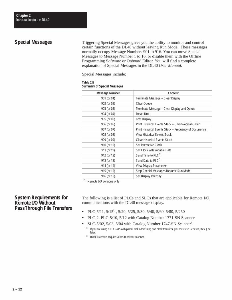
Triggering Special Messages gives you the ability to monitor and controlcertain functions of the DL40 without leaving Run Mode. These messagesnormally occupy Message Numbers 901 to 916. You can move SpecialMessages to Message Number 1 to 16, or disable them with the OfflineProgramming Software or Onboard Editor. You will find a completeexplanation of Special Messages in the DL40 User Manual.
Special Messages include:
Table 2.ESummary of Special Messages
Message Number Content
901 (or 01) Terminate Message – Clear Display
902 (or 02) Clear Queue
903 (or 03) Terminate Message – Clear Display and Queue
904 (or 04) Reset Unit
905 (or 05) Test Display
906 (or 06) Print Historical Events Stack – Chronological Order
907 (or 07) Print Historical Events Stack – Frequency of Occurrence
908 (or 08) View Historical Events Stack
909 (or 09) Clear Historical Events Stack
910 (or 10) Set Interactive Clock
911 (or 11) Set Clock with Variable Data
912 (or 12) Send Time to PLC➀
913 (or 13) Send Date to PLC➀
914 (or 14) View Display Parameters
915 (or 15) Stop Special Messages/Resume Run Mode
916 (or 16) Set Display Intensity➀ Remote I/O versions only
The following is a list of PLCs and SLCs that are applicable for Remote I/Ocommunications with the DL40 message display.
• PLC-5/11, 5/15➀ , 5/20, 5/25, 5/30, 5/40, 5/60, 5/80, 5/250
• PLC-2, PLC-5/10, 5/12 with Catalog Number 1771-SN Scanner
• SLC-5/02, 5/03, 5/04 with Catalog Number 1747-SN Scanner➁
➀ If you are using a PLC-5/15 with partial rack addressing and block transfers, you must use Series B, Rev. J orlater.
➁ Block Transfers require Series B or later scanner.
Special Messages
System Requirements forRemote I/O WithoutPassThrough File Transfers

Chapter 2Introduction to the DL40
2 – 13
The following tables list the Allen-Bradley PLCs and computer interfaceboards that are applicable for PassThrough file transfers with the DL40message display over a DH+ link.
Table 2.FApplicable PLC types for PassThrough file transfers over DH+
PLC Types Series Revision
PLC-5/11 All All
PLC-5/15 B N or later
PLC 5/20 All All
PLC 5/25 A J or later
PLC 5/30 A B or later
PLC 5/40 AB
E or later
PLC 5/60 AB
B or later
PLC 5/80 All All
PLC 5/250 All All
Table 2.GApplicable interface boards and modules for PassThrough file transfers over DH+
Catalog No. Description
1784-KT 1/2-slot interface board
1784-KTX 1/2-slot interface board
1784-KL Interface board for Allen-Bradley 1784-T45 or -T47
1784-KT2 Interface module for IBM PS2
1770-KF2 Serial to DH+ interface module
1784-PCMK PCMCIA interface board➀
➀ Requires 2706-ND1 Series D Version 3.0, which includes Interchange drivers.
The following table lists the Allen-Bradley PLCs that are applicable forPassThrough file transfers with the DL40 message display over an Ethernetlink.
Table 2.HApplicable PLC types for PassThrough file transfers over Ethernet
PLC Types Series Revision
PLC 5/40E AB
E or later
PLC 5/60E AB
B or later
PLC 5/80E All All
PLC 5/250 All All
System Requirements forRemote I/O PassThroughUsing DH+
System Requirements forRemote I/O PassThroughUsing Ethernet

Chapter 2Introduction to the DL40
2 – 14
Use one of the Allen-Bradley Ethernet computer interface boards (or itsequivalent) for PassThrough file transfers.
• Catalog Number 6628-A5
• Catalog Number 6628-A7
DL40 Message Displays are available with varying amounts of memory ineither two- or four-line versions.
Table 2.IProduct Identification and Catalog Numbers
Description Memory SizeRemote I/O
Communication VersionCatalog Number
Parallel Communication Port Versions Catalog
Number
Two Line Display 16 K MessageMemory
2706–E23J16B1 2706–E23J16
Two Line Display 32 K MessageMemory
2706–E23J32B1 2706–E23J32
Four Line Display 32 K MessageMemory
2706–E43J32B1 2706–E43J32
Four Line Display 64 K MessageMemory
2706–E43J64B1 2706–E43J64
Four Line Display 128 K MessageMemory
2706–E43J128B1 2706–E43J128
The following keyboards are compatible with the DL40 Message Display.
Table 2.JApplicable keyboards for use with the DL40 Message Display
Catalog No. Description
6120 & 6121 Allen-Bradley industrial computer standardkeyboards
1784-T50 Allen-Bradley industrial terminal keyboard
1784-T60 Allen-Bradley industrial terminal keyboard
IBM-PC or compatible -XT, -AT standard keyboard
IBM-PC or compatible -PC enhanced keyboard
NOTE: When used with the DL40, the Num Lock and Caps Lock indicatorswill not illuminate. We recommend you use the 1784-T60 terminal with NumLock turned off.
Catalog Numbers
Compatible Keyboards

Chapter 2Introduction to the DL40
2 – 15
The following options and accessories are available from Allen-Bradley forthe DL40 message display.
Table 2.KOptions and accessories for the DL40 message display
Item Description Catalog No.
OfflineProgramming
Software
Three 31/2 inch micro diskettes 2706-ND1
MemoryModules
Solid state backup for files and messages 16 Kbyte32 Kbyte64 Kbyte
2706-NMM162706-NMM322706-NMM64
CommunicationCables
For connecting the DL40 to a range of PCs, converters, andrecorders. Refer to Appendix B for detailed information oncables.
2706-NC122706-NC132706-NC142706-NC15
120 VoltParallel Input
Converter
Converter to connect 120 VAC input voltages to parallel inputport (2 required for each DL40)
2706-NG2
NEMAEnclosure
NEMA Type 12/13 enclosure complete with mounting holesand cutout for one DL40 display. Access door is gasketed.
Enclosure for two-line DL40Enclosure for four-line DL40
2706-NE12706-NE2
Keyboard FrontPanel Access
Kit
Panel mount 8-pin DIN keyboard connecter, NEMA 4 panelaccess cover, keyboard extension cable
2706-NKAK1
RS-232 FrontPanel Access
Kit
Panel mount 9-pin D shell connector, NEMA 4 panel accesscover, DL40 RS-232 extension cable
2706-NDAK2
Options & Accessories

Chapter
3Chapter 3Installing the Software
Figure 3Table 3
3 – 1
Chapter 3
Installing the Software
This chapter tells you how to install the DL40 Offline ProgrammingSoftware on your computer. It also explains the basic steps required toconfigure your system for use with PassThrough on systems equipped withan Allen-Bradley PLC capable of Remote I/O PassThrough file transfers.
The minimum equipment required to install and run the OfflineProgramming Software consists of an IBM compatible personal computer(PC) with:
• a 386 (or higher) processor
• 640K RAM
• one 31/2 inch micro diskette drive
• a hard disk with at least 1 Megabyte of available space
• one open serial port (COM1 or COM2)
• one open printer port (LPT1, LPT2, LPT3, LPT4, COM1, or COM2) forprinting messages
• a printer
In addition to this manual, the Offline Programming Software packageconsists of three disks and a number of documents. They include:
• a disk labeled DL40 Offline Programmer
• a disk labeled DL40 PassThrough
• a disk labeled INTERCHANGE DOS Runtime
After installing the software your PC will contain a DL40.EXE and aDL40.STP file to run the Offline Programming Software, as well as aPS.HLP file containing online help. If you install the PassThroughcapability you will also have the PassThrough files and their companion TSR(Terminate and Stay Resident) server files.
Important: In order for the Offline Programming Software to operatewithout generating warning messages about memory limitations, yourcomputer needs a minimum available memory of 570K RAM. Editing a128K message file requires the full 570K. Smaller message files will requireless computer memory.
With DOS versions prior to 5.0, use the CHKDSK↵ command at the DOSprompt to determine the available conventional RAM on your system. The
Personal ComputerRequirements
Package Contents
Memory Requirements

Chapter 3Installing the Software
3 – 2
available conventional RAM will be reported in bytes. Your system musthave 583,680 or more free bytes RAM to run the Offline ProgrammingSoftware and edit large application files.
With DOS versions 5.0 or higher, use CHKDSK ↵ or the MEM↵ command to accomplish the same task. (The MEM ↵ commands reportsmore quickly and in greater detail than does CHKDSK ↵ .) The valuereported for free conventional memory must be at least 570K.
The following table gives RAM recommendations for creating and editingmessage files and requirements for using PassThrough. If your computer hasless than the required bytes free, reduce the number of memory residentprograms (communications programs, mouse drivers, etc.) your computer isrunning. For additional information on increasing the amount of availablememory, refer to the configuration section of your computer’s DOS manual.
Table 3.APC memory requirements for typical activities
Function For a CHKDSK bytes free
Create and edit message files DL40 with 16 or 32Kbytemessage memory
460,000 bytes(recommended)
Create and edit message files DL40 with 64Kbytemessage memory
500,000 bytes(recommended)
Create and edit message files DL40 with 128Kbytemessage memory
580,000 bytes(recommended)
PLC–5 PassThrough w/DH+ PLC–5 with a DH+Communications Interface Card
515,000 bytes(required)
PLC–5 PassThrough w/EthernetPLC–5 with an Ethernet
Communications Interface Card &FTP’s PC/TCP Software
515,000 bytes(required)
Your PC’s system configuration at startup can affect the amount of RAMavailable for use by the Offline Programming Software. DOS offers anumber of options that can help increase the amount of RAM available toprograms.
With DOS versions 5.0 or earlier you can maximize available RAM byediting your CONFIG.SYS file. Your CONFIG.SYS should contain textlines similar the following:
DOS=HIGH, UMBDEVICE=C:\DOS\HIMEM.SYSBUFFERS=10FILES=10STACKS=9,128
In the example above, the BUFFERS, FILES, and STACKS values are set tolow values to conserve RAM for program operation.
Important: The line DOS=HIGH, UMB should be used only with DOSversions 5.0 or higher.
Memory Management

Chapter 3Installing the Software
3 – 3
DOS version 6.0 introduced the MEMMAKER command, which automatesmemory management and can often free large amounts of RAM. DOS 6.0and higher versions also allow you to create multiple configuration files fromwhich to choose at startup. This feature can prove useful on PCs used forprogramming the DL40 as well as other activities.
Refer to your DOS user manuals for information on creating and editingCONFIG.SYS files, techniques for optimizing memory, and using multipleconfiguration files on a single PC.
The Offline Programming Software can be installed and run in any of threedistinct environments:
• without PassThrough file transfers
• with PassThrough file transfers over a DH+ link
• with PassThrough file transfers over an Ethernet link
Installation of the basic Offline Programming Software is the same for allthree environments. You will have to perform additional steps to installPassThrough capability on either a DH+ or Ethernet link.
Use the following procedure to install the basic Offline ProgrammingSoftware files on an IBM PC. Note that prompts appearing here represent atypical PC. The prompts you see on your computer may vary slightly fromthose shown here.
1 Start your computer and log on to the hard disk (normally you will see theDOS prompt C:>).
Note: Depending on your installation, your DOS prompt may bedifferent.
2 Insert the DL40 Offline Programmer disk into the micro drive. Most oftenthis will be the A: drive.
3 At the DOS prompt (C:>), type:
A:INSTALL ↵
4 Follow the onscreen installation prompts until installation is complete andthe C:> prompt reappears. Note: If the Offline Programming Softwareprogram is already on disk, you will be able to overwrite the programduring installation.
5 The installation procedure automatically creates a default sub–directorywhich contains the Offline Programming Software program. By defaultthat directory is DL40. Change to that directory by typing:
CD\DL40 ↵
Installation
Basic Installation (Without PassThrough filetransfers)

Chapter 3Installing the Software
3 – 4
If you are using a DH+ link and want to enable PLC PassThrough filetransfers, you must perform the following additional steps after completingthe basic installation described above.
The following paragraphs outline only the most essential informationrequired to install and use PassThrough file transfers on a DH+ link. Refer tothe instructions that came with your DH+ add-in board.
Install and Configure Your DH+ Communication Interface Card
Install and configure your DH+ communication interface card. Refer to theinstructions that came with the card for information on how to install andconfigure it. As of the date this manual was prepared, the following DH+cards are supported by the Offline Programming Software:
– 1784-PCMK – 1784-KL
– 1770-KF2 – 1784-KT
– 1784-KT2 – 1784-KTX
Important: Be sure to record the IRQ and Card address for each interfacecard. You will need to know them later in the configurationprocess.
Install the Offline Programming Software
Perform the basic installation procedure described earlier in this chapter toinstall the Offline Programming Software on your personal computer.
Install and Configure INTERCHANGE
Your Offline Programming Software package contains a runtime version ofAllen-Bradley’s INTERCHANGE software and a number of other files.Installation of this package is required to perform PassThrough over a DH+network device.
INTERCHANGE software is an Application-Programming Interface (API)that provides a host computer running the MS-DOS operating system with alibrary of executable commands. INTERCHANGE software lets multipleapplications share a single common interface module to communicate withvarious devices on DH+ and/or DH-485 networks.
Use the following procedure to install INTERCHANGE:
1 Insert the INTERCHANGE disk into your 31/2 inch micro drive.
2 Start the automated installation procedure by typing:
A:INTCHG↵
Installing the Software forDH+ PLC PassThrough

Chapter 3Installing the Software
3 – 5
This program copies all required INTERCHANGE files to the directory\ABIC\BIN on your hard disk. Those files include the executableINTERCHANGE servers listed below:
– DTL_KT.EXE – CFG_DF1.EXE
– DTL_DF1.EXE – RNASTR.EXE
– CFG_KT.EXE – RNA.EXE
Important: The next part of the installation and configurationprocess depends on how you use your PC. If you useyour PC for other activities in addition to offlineprogramming, then you should create a new batch file asdescribed in step 3 below. If you use your PC solely forthe Offline Programming Software, then modify yourAUTOEXEC.BAT file as described in step 4 below.
3 If you use your PC for other activities in addition to offline programming,then create a new batch file containing the INTERCHANGE server fileslisted above. You can name the file anything you want, but it must endwith the extension .BAT. For purposes of illustration, assume you will callthe file ABICRUN.BAT, and assume your hard drive is drive C:
a. Create the file with any ASCII text editor. If you use the DOS texteditor, type:
EDIT C:\ABICRUN.BAT ↵
b. Type in the names of the INTERCHANGE server files. Put each filename on its own line followed by a hard return:
DTL_KT.EXEDTL_DF1.EXECFG_KT.EXECFG_DF1.EXERNASTR.EXERNA.EXE
c. Save the file. If you are using the DOS text editor, type:
[ALT]FXY
d. Skip step 4 and go on to step 5.
4 If you use your PC solely for the Offline Programming Software, youneed not create a new batch file. Instead, you should modify yourAUTOEXEC.BAT file to load the INTERCHANGE server fileswhenever you start your system.
a. Open the AUTOEXEC.BAT file with any ASCII text editor. If youuse the DOS text editor, type:
EDIT C:\AUTOEXEC.BAT ↵
Your AUTOEXEC.BAT file contents will appear in the editingwindow.
b. Move the cursor to the end of the file.

Chapter 3Installing the Software
3 – 6
c. Type in the names of the INTERCHANGE server files. Put each filename on its own line followed by a hard return:
DTL_KT.EXEDTL_DF1.EXECFG_KT.EXECFG_DF1.EXERNASTR.EXERNA.EXE
Do not close the file at this time.
5 If your AUTOEXEC.BAT is not open in your ASCII text editor, thenopen it now. If you use the DOS text editor, type:
EDIT C:\AUTOEXEC.BAT ↵
Your AUTOEXEC.BAT file contents will appear in the editing window.
6 Locate the line in your AUTOEXEC.BAT file that begins with the wordPATH. This is your system’s “Path Statement”, which tells DOS where tolook for executable files when no specific path is otherwise specified.
7 Move to the end of the Path line and insert the complete name for thedirectory in which the INTERCHANGE server files were stored. In astandard installation they are located in C:\ABIC\BIN. When you havefinished editing it, your Path Statement will look something like this:
PATH=C:\DOS;C:\APP1;C\APP2;C:\ABIC\BIN
Create CFG_KT.INI File
INTERCHANGE needs to know exactly what hardware you are using, andhow it is configured. It takes that information from a configuration file(CFG_KT.INI) you modify to match your own installation.
8 You can edit the file with any ASCII text editor. If you use the DOS texteditor, type:
EDIT C:\ABIC\BIN\CFG_KT.INI ↵
The CFG.INI file that installs with INTERCHANGE includesconfigurations for numerous cards. Lines preceded by a semicolor (;)have been commented out. To activate your interface card, edit anduncomment the appropriate options by removing the semicoloen at thebeginning of the line.
If you are using a card other than the 1770-KF2 to to step 9 below. If youare using the 1770-KF2 communications interface card skip step 9 belowand go directly to step 10.
Chapter 3Installing the Software
3 – 7
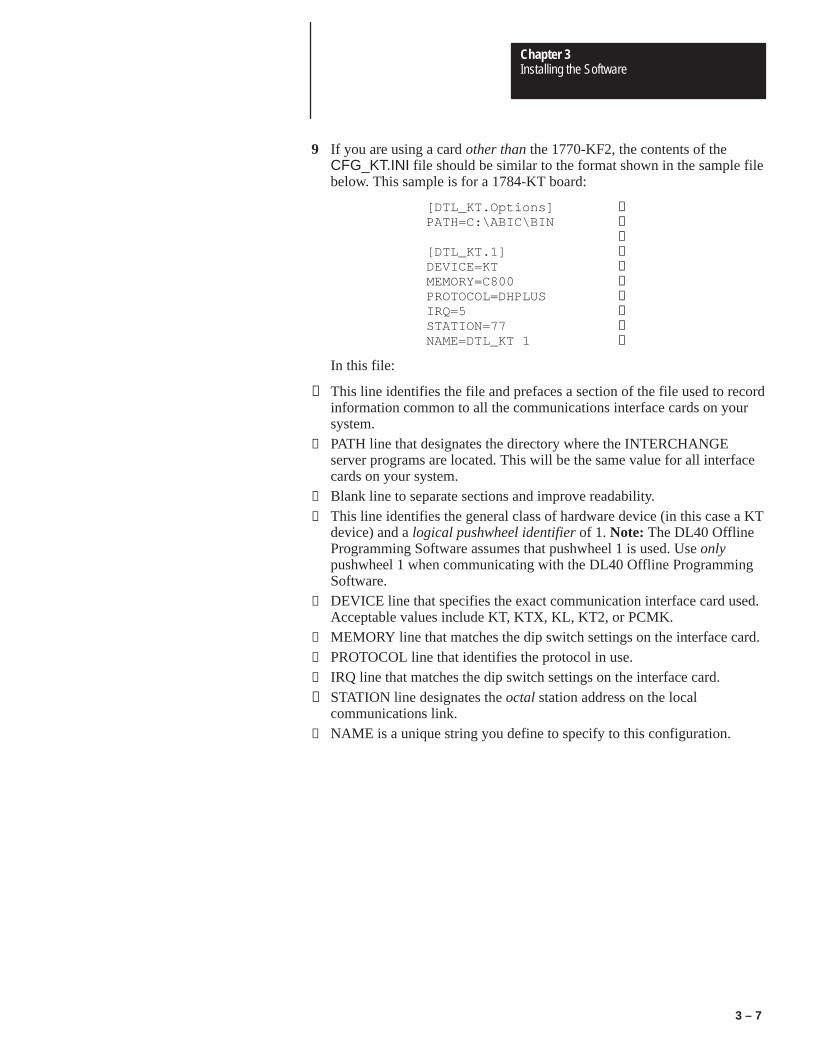
9 If you are using a card other than the 1770-KF2, the contents of theCFG_KT.INI file should be similar to the format shown in the sample filebelow. This sample is for a 1784-KT board:
[DTL_KT.Options] ①PATH=C:\ABIC\BIN ②
③[DTL_KT.1] ④DEVICE=KT ⑤MEMORY=C800 ⑥PROTOCOL=DHPLUS ⑦IRQ=5 ⑧STATION=77 ⑨NAME=DTL_KT 1 ⑩
In this file:
① This line identifies the file and prefaces a section of the file used to recordinformation common to all the communications interface cards on yoursystem.
② PATH line that designates the directory where the INTERCHANGEserver programs are located. This will be the same value for all interfacecards on your system.
③ Blank line to separate sections and improve readability.④ This line identifies the general class of hardware device (in this case a KT
device) and a logical pushwheel identifier of 1. Note: The DL40 OfflineProgramming Software assumes that pushwheel 1 is used. Use onlypushwheel 1 when communicating with the DL40 Offline ProgrammingSoftware.
⑤ DEVICE line that specifies the exact communication interface card used.Acceptable values include KT, KTX, KL, KT2, or PCMK.
⑥ MEMORY line that matches the dip switch settings on the interface card.⑦ PROTOCOL line that identifies the protocol in use.⑧ IRQ line that matches the dip switch settings on the interface card.⑨ STATION line designates the octal station address on the local
communications link.⑩ NAME is a unique string you define to specify to this configuration.

Chapter 3Installing the Software
3 – 8
Models for other interface cards appear below. Note that some of thevalues in these files will vary depending on your own installation.
1784-KT2
[DTL_KT.Options]PATH=C:\ABIC\BIN
[DTL_KT.1]DEVICE=KT2MEMORY=C400PROTOCOL=DHPLUSIRQ=5STATION=77NAME=DTL_KT2
1784-KL
[DTL_KT.Options]PATH=C:\ABIC\BIN
[DTL_KT.1]DEVICE=KLMEMORY=E000PROTOCOL=DHPLUSIRQ=2STATION=77NAME=DTL_KL 1
1784-KTX
[DTL_KT.Options]PATH=C:\ABIC\BIN
[DTL_KT.1]DEVICE=KTXMEMORY=D400PROTOCOL=DHPLUSIRQ=10STATION=77NAMWE=DTL_KTX1
1784-PCMK
[DTL_KT.Options]PATH=C:\ABIC\BIN
[DTL_KT.1]DEVICE=PCMKMEMORY=CF00PROTOCOL=DHPLUSIRQ=7STATION=77NAME=DTL_PCMK

Chapter 3Installing the Software
3 – 9
10 If you are using the 1770-KF2 communications interface card, thecontents of the CFG_KT.INI file should be similar to the format shown inthe sample file below:
[DTL_KT.Options]PATH=C:\ABIC\BIN
[DTL_DF1.1]DEVICE=DF1BAUD=9600IRQ=4COM_PORT=2NAME=DTL_DF1ERROR=1 ①PARITY=0 ②DUPLEX=1 ③
① 0=BCC,1=CRC② 0=No Parity, 1=Even Parity③ 0=Half Duplex, 1=Full Duplex
11 Save the file. If you are using the DOS text editor, type:
[ALT]FXY
If you are using an Ethernet link and want to enable PLC PassThrough filetransfers, you must first modify your CONFIG.SYS and AUTOEXEC.BATfiles, and install and configure the following products on your PC:
• Allen-Bradley Ethernet communications interface card (Cat. Nos.6628-A5 or -A7) or equivalent
• FTP’s PC/TCP Software for DOS/Windows (FTP Cat. No. PC-210)
Install Ethernet Card
Follow the instructions that came with your Allen-Bradley Ethernetcommunications interface card to install and configure it on your personalcomputer.
Install the PC/TCP Software
Follow the instructions that came with FTP’s PC/TCP Software to install iton your personal computer.
Install the Offline Programming Software
Perform the basic installation procedure described earlier in this chapter toinstall the Offline Programming Software on your personal computer.
Installing the Software forEthernet PLC PassThrough

Chapter 3Installing the Software
3 – 10
Modify CONFIG.SYS & AUTOEXEC.BAT Files
The following steps show a sample network setup. Consult with yournetwork administrator to determine if this setup applies in your environment.
1 Change to the directory containing the PC/TCP drivers. Type:
CD \PCTCP↵
2 At the C:\PCTCP> prompt, type:
RENAME FTP22DOS.INI PROTOCOL.INI
3 Open the CONFIG.SYS file with any ASCII text editor. If you use theDOS text editor, type:
EDIT C:\CONFIG.SYS ↵
Your CONFIG.SYS file contents will appear in the editing window.
4 Move the cursor to the end of the file.
5 Assuming you have installed the Ethernet Board drivers in the directoryC:\PCTCP (the default), be sure the following lines appear in yourCONFIG.SYS file.
DEVICE=C:\PCTCP\PROTMAN.DOS /I:C:\PCTCPDEVICE=C:\PCTCP\SMC8000.DOSDEVICE=C:\PCTCP\DIS_PKT.GUP
6 Save the file. If you are using the DOS text editor, type:
[ALT]FXY
7 Open the AUTOEXEC.BAT file with any ASCII text editor. If you usethe DOS text editor, type:
EDIT C:\AUTOEXEC.BAT ↵
Your AUTOEXEC.BAT file contents will appear in the editing window.
8 Move the cursor to the end of the file.
9 The following lines should appear in the AUTOEXEC.BAT file. If theyare not there, add them now.
SET PCTCP=C:\PCTCP\PCTCP.INIC:\PCTCP\NETBIND.COMC:\PCTCP\ETHDRV.EXE
For additional information regarding installation of your PC/TCP software,refer to the section on installing an NDIS driver in the PC/TCP SoftwareInstallation Guide.
Restart Your PC
When installation is complete, remove the installation diskette from the 31/2inch micro drive and store all installation software in a safe place. Finally,

Chapter 3Installing the Software
3 – 11
restart your PC to activate your changes to the CONFIG.SYS andAUTOEXEC.BAT files.
Configure Your PLC
Use Allen-Bradley’s 6200 Series PLC-5 programming software or theEIBOOT utility to set the PLC’s IP address. Refer to the documentation thatcame with your PLC for additional information on configuration.
If you have installed the Offline Programming Software withoutPassThrough processing, your computer will return to the DOS prompt,C:\DL40>. If you have installed PassThrough processing, your computerwill return to whatever directory it displayed when you began thePassThrough processing installation.
If you do not return to the C:\DL40> directory, change directories by typing:
CD C:\DL40 ↵
You may then start the the Offline Programming Software program bytyping:
DL40↵
The communication port settings on your computer and the DL40 must bethe same in order to communicate.
• the port usage on the RS-485 port must be set to PRGMR to performmessage file transfers via the RS-485 port.
• the DL40 RS-232 port is always configured for communications with theDL40 Offline Programming Software.
• set your computer’s serial communication port to the following:
– baud rate 9600
– data bits 8
– parity none
– handshaking none
• Use the [SELECT] and [ENTER] push buttons on the front panel of theDL40 to select SET RS232 PORT?–PGMR/PRNTER SETUP or SETRS-485 PORT?–PRGMR and set the parameters to match the setting ofyour computer’s serial communication port.Note: Select Enable DIP switch (SW2-9) must be ON.
• You can also change the settings of the DL40’s serial ports with the[CTRL]R command using the DL40’s Onboard Editor and an IBMcompatible keyboard connected to the rear keyboard port of the DL40display.
Starting the Program
Establishing InitialCommunications InNon-Networked Installations

Chapter
4Chapter 4Navigating the Software
Figure 4Table 4
4 – 1
Chapter 4
Navigating the Software
This chapter provides the basic understanding you will need to move aroundin the DL40 Offline Programming Software. The information it contains willhelp you:
• start the program
• move around within the program
• exit the program
After you have installed and set up the Offline Programming Software onyour PC, you can run the program at any time. The most basic way to do sois to:
1 Start your computer.
2 Make sure you are logged on to the C: drive by typing:
C: ↵
3 Go to the directory C:\DL40 by typing:
CD C:\DL40 ↵
4 Start the program by typing:
DL40↵
Starting the Program

Chapter 4Navigating the Software
4 – 2
The program opens with the Title screen shown in Figure 4.1. The screenidentifies the product, and indicates the revision number and date of thatcopy of the software. You can close this screen and open the Main Screen(shown in Figure 4.2) by pressing any key.
Figure 4.1Opening screen
Figure 4.2Main screen
Cursor Menu Bar
Date & Time
Menu Title
Menu Choice
Title Screen & Main Menu Bar

Chapter 4Navigating the Software
4 – 3
The Offline Programming Software offers context-sensitive online Help atany time. To use Help:
• press [F1] to access a Help screen offering information about thehighlighted menu item.
• press [F1] again to replace the current Help screen with the Menu KeyControl Help screen.
• press [ESC] to close the Menu Key Control Help screen and return to thecontext-sensitive Help screen
• press [ESC] to close the context-sensitive Help screen and return to theMain screen
Figure 4.3Sample Help Screen
Getting Help

Chapter 4Navigating the Software
4 – 4
Use the Setup menu to match the software to your color or monochromemonitor, and to set the date and time. You can get to the Setup menu by usingthe right and left arrow keys to move to Setup and pressing [↵ ], or bypressing [S] at the Main menu.
Figure 4.4The Setup Menu
The Setup Menu

Chapter 4Navigating the Software
4 – 5
Configuring the Program to Match Your Monitor
The Offline Programming Software supports both color and monochromedisplays. To change the display type, move the cursor to Setup on the Mainmenu and press [↵ ]. Select Colors, and then select either Color orMonochrome. Select Yes to confirm your choice, the press [↵ ]. A pop-upmessage will appear briefly in the center of your screen to indicate that thesoftware is saving your selection to its setup file. Press [Q] or [ESC]repeatedly to return to the Main menu.
Figure 4.5The Setup→Colors Screen

Chapter 4Navigating the Software
4 – 6
Setting Time & Date
You can set the time and date by selecting Setup→Time & Date or bypressing [S][T] from the the Main menu bar. The Date & Time window willappear showing the current date and time setting of the personal computer.The cursor will highlight Time when the window first opens. Press [↵ ] andinput the desired time using military style (24-hour) format. Press [↵ ] torecord your changes and move the cursor to Date. Press [↵ ] and input thedesired date. Press [↵ ] to record your changes and move the cursor to Quit.
Figure 4.6The Setup→Time & Date Screen
Chapter 4Navigating the Software
4 – 7
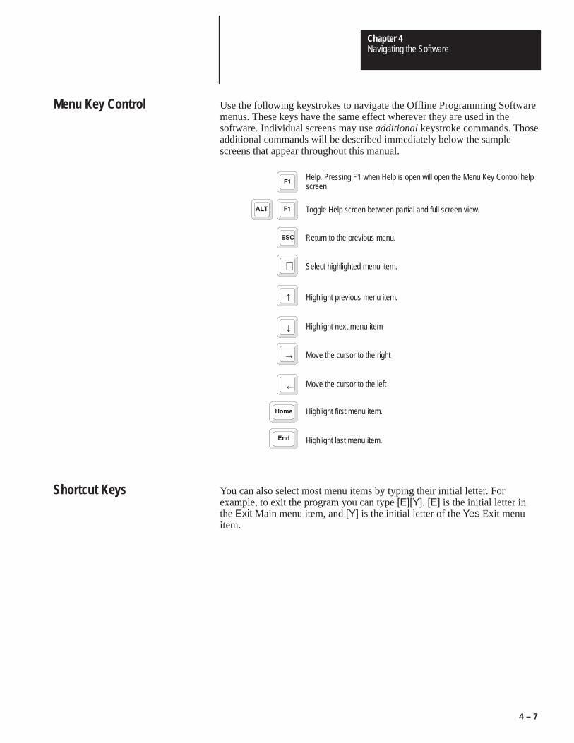
Use the following keystrokes to navigate the Offline Programming Softwaremenus. These keys have the same effect wherever they are used in thesoftware. Individual screens may use additional keystroke commands. Thoseadditional commands will be described immediately below the samplescreens that appear throughout this manual.
Help. Pressing F1 when Help is open will open the Menu Key Control helpscreen
Toggle Help screen between partial and full screen view.
Return to the previous menu.
↵ Select highlighted menu item.
↑ Highlight previous menu item.
↓ Highlight next menu item
→ Move the cursor to the right
← Move the cursor to the left
Highlight first menu item.
Highlight last menu item.
You can also select most menu items by typing their initial letter. Forexample, to exit the program you can type [E][Y]. [E] is the initial letter inthe Exit Main menu item, and [Y] is the initial letter of the Yes Exit menuitem.
Menu Key Control
Shortcut Keys
Chapter 4Navigating the Software
4 – 8
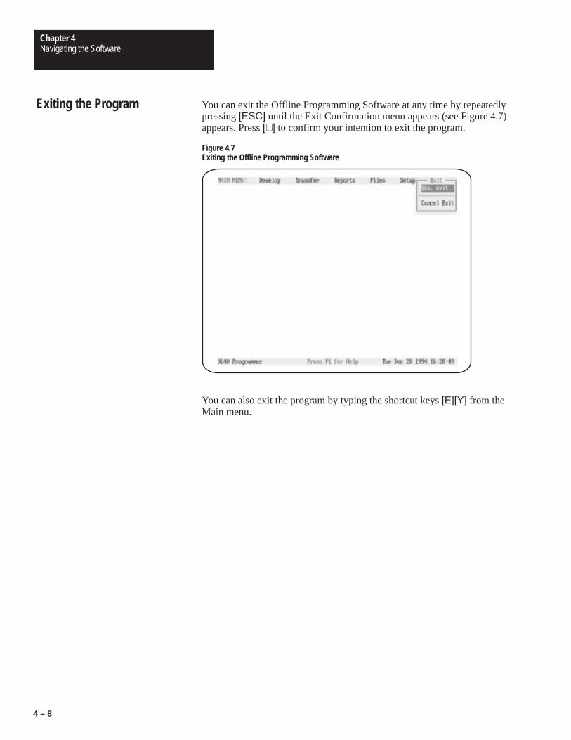
You can exit the Offline Programming Software at any time by repeatedlypressing [ESC] until the Exit Confirmation menu appears (see Figure 4.7)appears. Press [↵ ] to confirm your intention to exit the program.
Figure 4.7Exiting the Offline Programming Software
You can also exit the program by typing the shortcut keys [E][Y] from theMain menu.
Exiting the Program

Chapter
5Chapter 5The Develop Menu
Figure 5Table 5
5 – 1
Chapter 5
The Develop Menu
This chapter describes the functions available to you from the Develop menu.As its name implies, the options available from this menu provide the toolsneeded to create and manage your application files for the DL40 messagedisplay.
To open the Develop menu, use the right and left arrow keys to highlightDevelop on the Main menu bar, then press [↵ ].
Selecting Develop on the Main menu bar will result in display of theDevelop menu.
Figure 5.1Develop Menu
Develop Menu Top Level
Chapter 5The Develop Menu
5 – 2
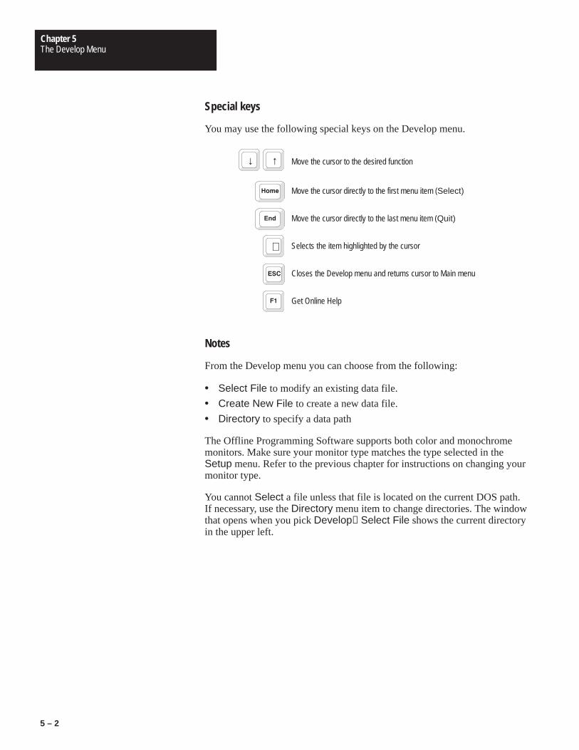
Special keys
You may use the following special keys on the Develop menu.
↓ ↑ Move the cursor to the desired function
Move the cursor directly to the first menu item (Select)
Move the cursor directly to the last menu item (Quit)
↵ Selects the item highlighted by the cursor
Closes the Develop menu and returns cursor to Main menu
Get Online Help
Notes
From the Develop menu you can choose from the following:
• Select File to modify an existing data file.
• Create New File to create a new data file.
• Directory to specify a data path
The Offline Programming Software supports both color and monochromemonitors. Make sure your monitor type matches the type selected in theSetup menu. Refer to the previous chapter for instructions on changing yourmonitor type.
You cannot Select a file unless that file is located on the current DOS path.If necessary, use the Directory menu item to change directories. The windowthat opens when you pick Develop→Select File shows the current directoryin the upper left.

Chapter 5The Develop Menu
5 – 3
When Select File is selected, a window will appear with the default path inthe upper left corner and a list of the files found in that path. If you want toedit files under a different path, press [ESC], highlight Directory, and press[↵ ]. You can then edit the program’s data path in the pop-up window shownin Figure 5.4.
Figure 5.2File Selections screen showing typical application file list
Path
Time file was createdor last edited
Date file was created orlast edited
File length in bytes
Special keys
You may use the following special keys on the File Selections screen.
↓ ↑ Move the cursor to the desired file
Move the cursor directly to the first file
Move the cursor directly to the last file
↵ Selects the item highlighted by the cursor (Goes to Develop Screenillustrated in Figure 5.5)
Returns to the top level of the Develop menu
Get Online Help
File Selections Screen

Chapter 5The Develop Menu
5 – 4
Notes
Use the arrow keys to move to the file you want to edit and press [↵ ]. If thename of the file you want to edit does not appear here, you may be using thewrong data path. You can change the data path by backing up and selectingDirectory on the Develop menu.
When Create New File is selected on the Develop menu, the program willpresent a window in which you can type name a new file. Type in the filename and press [↵ ]. You can type a drive and directory path as well if youdo not want to store the file on the current data path.
Figure 5.3Create New File pop-up window
Flashing cursor
If the default path is to be used, enter onlythe file name. If a path other than thedefault path is to be used, enter the pathin the form: Drive:\Directory\File.
Special keys
You may use the following special keys on this window.
← → Moves the cursor forward or backward through the file name to allowediting
↵ Accepts the file name (and path, if applicable). (Goes to Develop Screenillustrated in Figure 5.5)
Returns to the top level of the Develop menu
Get Online Help
Create New File Pop-upWindow

Chapter 5The Develop Menu
5 – 5
Notes
When creating a new file you will be asked to specify a path and filename inthe form:
Drive:\Directory\File
If you do not specify a path, then the currently active path will be used.
When you press [↵ ] to accept the file name in the Create a New File pop-upwindow, the Device menu (illustrated in Figure 5.22) will appear.
You can change data path directories by selecting Develop→Directory fromthe Main menu bar. When you enter a complete directory path in theDirectory pop-up window the Offline Programming Software will use thatpath as a default for all file activities. You can override the Directory settingby typing another complete data path when naming files.
Figure 5.4Data Path Directory window
Data Path Directory Pop-upWindow

Chapter 5The Develop Menu
5 – 6
Special keys
You may use the following special keys on this window.
← → Moves the cursor forward or backward through the data path description toallow editing
↵ Accepts the data path directory you have entered in the pop-up window
Returns to the top level of the Develop menu
Get Online Help
Notes
When creating a new data path, specify the path in the form:
Drive:\Directory1\Directory2\Directory3
You can change the selected data path directory at any time the Messagemenu is displayed. The change will become effective immediately.
Editing an existing file and creating a new file both involve the same steps,so the same screen can be used for both activities. After you have specifiedthe name and data path of a file to create or change, the screen shown belowappears. Notice that the Main menu bar has been replaced by a the Developmenu bar. You can navigate on this menu bar exactly as you would on theMain menu bar.
Develop Screen Menu Bar

Chapter 5The Develop Menu
5 – 7
Figure 5.5Develop Screen menu bar as it appears after selecting or creating a file
Remaining (free) memory
Special keys
You may use the following special keys on this menu.
← → Moves the cursor to the desired function
Moves the cursor directly to the desired function: Messages, Options,Ports, Verify, or Exit.
Moves cursor directly to the first function (Messages)
or Moves cursor directly to the last function (Exit)
↵ Selects the function highlighted by the cursor
Get Online Help
Notes
The Messages, Options, Ports, Verify, and Device branch menus allowyou to exercise precise control over every aspect of your message file. It isgood practice to work through each of these menus in turn to avoidomissions and mistakes.

Chapter 5The Develop Menu
5 – 8
You must specify a selection for every item on the Develop menu bar branchmenus. If you have not edited every selection, then you will see a SystemAttribute Warning message when you save the file.
Each branch menu available from the Develop menu bar is illustrated andexplained in the pages that follow.
Use the selections on the Messages menu to create, edit, and control thedisplay format of messages intended for display on the DL40.
Figure 5.6Messages menu
Messages Menu

Chapter 5The Develop Menu
5 – 9
Special keys
You may use the following special keys on this menu.
↓ ↑ Move the cursor to the desired function
Move the cursor directly to the first menu item
Move the cursor directly to the last menu item (Quit)
↵ Selects the item highlighted by the cursor
Closes the Develop menu and returns cursor to Main menu
Get Online Help
After you have selected Edit Message, the Message Selections pop-upwindow shown in Figure 5.7 will open on the screen. Select the message youwant to edit, then press [↵ ] to open the Message Text window shown inFigure 5.8.
Figure 5.7Message Selections pop-up, which appears after you select Edit Message
Edit Message Screen
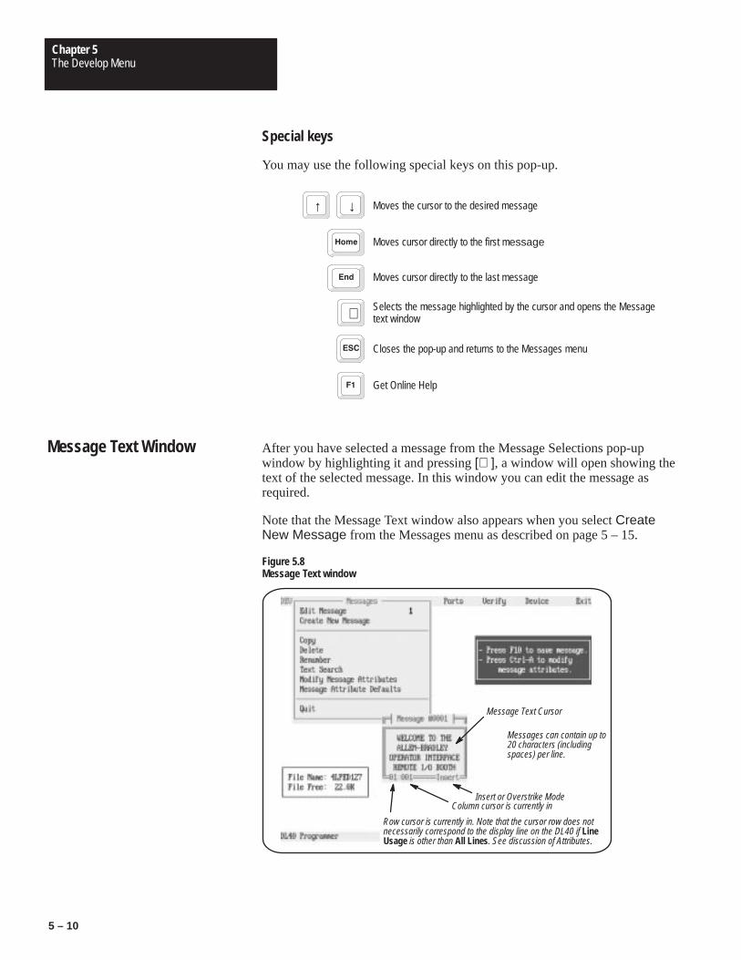
Chapter 5The Develop Menu
5 – 10
Special keys
You may use the following special keys on this pop-up.
↑ ↓ Moves the cursor to the desired message
Moves cursor directly to the first message
Moves cursor directly to the last message
↵ Selects the message highlighted by the cursor and opens the Messagetext window
Closes the pop-up and returns to the Messages menu
Get Online Help
After you have selected a message from the Message Selections pop-upwindow by highlighting it and pressing [↵ ], a window will open showing thetext of the selected message. In this window you can edit the message asrequired.
Note that the Message Text window also appears when you select CreateNew Message from the Messages menu as described on page 5 – 15.
Figure 5.8Message Text window
Message Text Cursor
Messages can contain up to20 characters (includingspaces) per line.
Insert or Overstrike ModeColumn cursor is currently in
Row cursor is currently in. Note that the cursor row does notnecessarily correspond to the display line on the DL40 if LineUsage is other than All Lines. See discussion of Attributes.
Message Text Window

Chapter 5The Develop Menu
5 – 11
Special keys and Editing Rules
You may use the following keys to move through and edit your message text.
↑ ↓ Moves the cursor up or down one line at a time
← → Moves the cursor right or left without changing the underlying text
or Moves cursor directly to the beginning or end of the message
or Moves cursor exactly 1 display window forward or backward through themessage (except when Scroll attribute is set as described on page 5 – 25
Toggles between insert and overstrike. If there is a character at the positionof the cursor, then the insert mode inserts a character immediately to theleft of the cursor. In overstrike mode the character at the cursor position isreplaced by any new character you type.
Deletes the character to the left of the cursor
Deletes the character at the cursor position
↵ Inserts a return to start a new line
ALT Press the [ALT] key while entering a number from the numeric keypadwill insert an ASCII or Extended ASCII character. See Appendix C
Any alphabetic or numeric key Inserts that character at the position of the cursor.
plus V F W X T Yor Add or modify variables (see below)
ALets you set Message Attributes for only the message being created oredited.
BStart and end marker for blinking characters. Must be used in pairs. Thetext between the markers will blink on the message display.
EErases message text, but leaves message number intact. You will beasked to confirm this action before it takes effect.
N Centers or un-centers the active message in the Edit Message window.
Returns to Messages menu. Note that the Abort Message Edit confirmationpop-up will appear if you have changed the message in any way. Thepop-up will ask if you want to discard your changes.
Get Online Help
Toggles size of Message Text window between 40 and 200 characters
F10 Saves changes and returns to the Messages menu

Chapter 5The Develop Menu
5 – 12
More about variables
You can send variables to the DL40 from a PLC or via the Parallel InputPort. Variables can be sent to message only in the Message/Variable/Slave orMessage/Variable Run Modes. You can insert variables by using the [CTRL]key in combination with a letter. Commands to add or modify variablesinclude:
Command Function
[CTRL][V] Insert a BCD or binary variable
[CTRL][F] Change the formatting parameters of a variable
[CTRL]W] Insert ASCII or BCD variable data
[CTRL][X] Insert request for ASCII input data
[CTRL][T] Insert the system time into a message
[CTRL][Y] Insert the system date into a message
The number of variables you can insert in any one message depends uponyour hardware and the Run Mode you have chosen.
Insert Formatted Variable With [CTRL][V]
Use [CTRL][V] to insert a BCD or binary variable into a message. Specifythe variable type.
When you press [CTRL][V], the software will ask you to enter 3 parameters:
Parameter Acceptable values
Variable Size 1 to 7 (including decimal point)
Decimal Point Position(number of placed after thedecimal point)
0 to 6 (the maximum value is one less than thevariable size selected above)
Suppress Zeroes(appearing in front of thefirst significant digit)
Yes or No
The variable symbol _____�____ will appear in your message at thevariable’s location.
The difference between a formatted variable entered with [CTRL][V] and anunformatted variable entered with [CTRL][W] lies in the flexibility providedby the ability to modify the parameters shown above.
Note that neither AutoRun Messages or Background Messages supportinserted variable data.
Change Formatted Variable With [CTRL][F]
Use [CTRL][F] to change the formatting parameters of a variable. To do so,place the cursor under the symbol for the variable you want to change, then

Chapter 5The Develop Menu
5 – 13
press [CTRL][F]. The software will ask you to modify any one or more of the3 formatting parameters described above:
Parameter Acceptable values
Variable Size 1 to 7 (including decimal point)
Decimal Point Position(number of placed after thedecimal point)
0 to 6 (the maximum value is one less than thevariable size selected above)
Suppress Zeroes(appearing in front of thefirst significant digit)
Yes or No
Insert ASCII or BCD Variable With [CTRL][W]
You can send a single word ASCII or BCD variable for insertion into amessage. Use [CTRL][W] to specify the insertion position. The software willprompt you to specify either ASCII or BCD. The software will insert thesymbol for an ASCII or BCD variable (↕).
Note: BCD data consists of 4 digits per word, and ASCII data consists of 2characters per word.
Note: Variables can be strung together to form compound variables up to 20ASCII or 40 BCD characters long in any combination as long as the totaldoes not exceed 10 words.
Insert Request for ASCII Input Data With [CTRL][X]
A data request requires that ASCII Input Data, an 8-bit ASCII character, beentered through the keyboard port into the message being displayed.
• When returning ASCII Input Data via RS-485 Port, the messagerequesting the data must be triggered via the RS-485 Port. This is true forboth Parallel Port and Remote I/O units. Data is automatically enteredwhen you press [↵ ].Note: Data is returned to the triggering device without solicitation by thedevice and without an checking that data was received by the device.
• With Remote I/O units, the ASCII input data will be sent via Remote I/OPort to your PLC as part of the Return Message Number Being Displayed(described in the Bulletin 2706 Dataliner Message Display DL40 SeriesUser Manual, Publication 2706-807). Data can be returned to your PLCin:
– Message/Variable/Slave Run Mode
– Message/Variable Run Mode
– Message List Run Mode

Chapter 5The Develop Menu
5 – 14
User requested data is sent to the PLC as part of the I/O scan. Up to 20ASCII characters can be sent with Block Transfer. Up to 12 ASCIIcharacters can be sent with Discrete, depending on rack size.
The Enter bit will be set only after all ASCII data requested has been putinto the message. Data should not be considered valid until the Enter bit isset.
Important: If more ASCII data is requested than can be returned tothe PLC, the excess data will be lost.
To enter a data request, place the cursor just after the point where you wantto insert the request. Use [CTRL][X] to specify the insertion position. Thesoftware will insert the symbol for a single byte data request (↑ ).
Insert Time Into a Message With [CTRL][T]
To enter the time into a message, place the cursor just after the point whereyou want the time inserted. Use [CTRL][T] to specify the insertion position.The software will insert the symbol for a time variable (HH:MM:SS).
Note: The time variable occupies 8 of the available 20 characters on adisplay line.
You can use the time variable in any Run Mode.
Insert Date Into a Message With [CTRL][Y]
To enter the date into a message, place the cursor just after the point whereyou want the date to appear, and then press [CTRL][Y]. The software willinsert the date symbol (DAY MON DT).
Note: The date variable occupies 10 of the available 20 characters on adisplay line.
You can use one date variable in any message in any Run Mode.
Notes
We recommend setting individual message attributes such as DisplayMessage on What Line and Scroll Message before typing in the words ofthe message. This allows you to verify the placement of characters as youtype them.
If Line Usage is other than All Lines, then the display line on the DL40does not necessarily correspond to the cursor row value shown on themessage editing window during editing.

Chapter 5The Develop Menu
5 – 15
After you have pressed [↵ ] to select Create New Message from theMessages menu, the message number field (to the right of the menu item)will open. Enter the message number you want to assign to the new messageand press [↵ ] again. The Message Text window shown below and describedin detail on page 5 – 10 will open. You can use the Message Text window todevelop and format your message text.
Figure 5.9Create New Message screen and Message Text window
Notes
We recommend setting individual message attributes such as DisplayMessage on What Line and Scroll Message before typing in the words ofthe message. This allows you to verify the placement of characters as youtype them.
If Line Usage is other than All Lines, then the display line on the DL40does not necessarily correspond to the cursor row value shown on themessage editing window during editing.
If the message number you have assigned is already being used for anexisting message, the software will display a warning message. You can thenchoose between cancelling the creation or editing the existing message.
If adding new messages would exceed the capacity of your DL40, thesoftware will display a warning message and automatically cancel the createfunction.
Create New Message

Chapter 5The Develop Menu
5 – 16
When you select Copy from the Messages menu, the MessageSelections/Message Picks pop-up window opens. All message numbers in thecurrent file will appear in the Message Selections column.
After you have moved all the messages to be copied into the Message Pickscolumn, press [F10] and the Start/Increment pop-up window will appear.When it does, press [↵ ] to open the Starting Message Location field. Inputthe new message number you want to assign to the first message on your list.Insert a value in the Increment field if you are copying multiple messages.
For example, suppose you want to copy message numbers 1, 2, and 3 to astarting number of 10 and an increment of 5. As a result:
Message 1 would be copied, and the copy assigned a messagenumber of 10.
Message 2 would be copied, and the copy assigned a messagenumber of 15.
Message 3 would be copied, and the copy assigned a messagenumber of 20.
When you press [F10] to accept your Message Picks, the Copy Messageconfirmation pop-up- will appear. Use the arrow keys to highlight yourchoice and press [↵ ].
Figure 5.10Copy (Messages) screen showing the Message Picks/Message Selections pop-up with messagesone and two selected. Also show are the Start/Increment pop-up and the Copy Messagesconfirmation pop-up.
Start/Incrementpop-up window
.
Copy (Messages) Screen

Chapter 5The Develop Menu
5 – 17
Special keys
You may use the following special keys on this screen.
← → Moves the Message Select cursor to the Message Selections or MessagePicks column
↑ ↓ Moves the Message Select cursor up or down within a column
↵ Moves the highlighted message number from one column to the other
Get Online Help
Accept message picks
Closes the Message Selections/Message Picks pop-up without takingaction
Notes
To copy a block of messages, move the cursor to the first message on theblock and press [CTRL][B] to mark the beginning of the block. Then movethe cursor to the last message in the block and press [↵ ]. The entire blockwill be moved to the opposite column.
If you leave the increment set to 0, the spacing between messages will beretained . For example, copying message numbers 1, 3, and 7 to messagenumber 10 with an increment of 0 will result in new copies with messagenumbers 10, 12, and 16.
If any of the destination message numbers you have assigned are alreadybeing used for an existing message, the software will display a warningmessage. You can cancel the copy, continue and overwrite the selectedexisting message, skip this message, or continue and overwrite all existingmessages.
If adding new messages would exceed the capacity of your DL40, thesoftware will display a warning message and automatically cancel the copyfunction.
Messages will be copied with the following conditions:
• Messages selected for copying appear on the Message Picks list in theorder they were selected. They do not need to be listed in numeric order.The message with the lowest number will always be copied to the Startnumber, the message with the next lowest number will be copied to thefirst Increment number, and so on.
• In any of the destination message numbers are already in use by anexisting message, a warning will appear and give you a chance to cancel

Chapter 5The Develop Menu
5 – 18
the operation, continue the copy and overwrite the existing message, orcontinue and overwrite all existing messages.
• If adding newly copied messages will exceed the capacity of your DL40,a warning message will appear, and the copy function will be cancelled.
When you select Delete from the Messages menu, the MessageSelections/Message Picks pop-up window opens. All message numbers in thecurrent file will appear in the Message Selections column. After you havemoved all the messages to be deleted into the Message Picks column, press[F10].
When you press [F10] to accept your Message Picks, the Delete Messageconfirmation pop-up will appear. Use the arrow keys to highlight your choiceand press [↵ ].
Figure 5.11Delete (Message) screen with Delete Message confirmation pop-up window
Delete MessageConfirm pop-up window
Delete (Message) Screen

Chapter 5The Develop Menu
5 – 19
Special keys
You may use the following special keys on this screen.
← → Moves the Message Select cursor to the Message Selections or MessagePicks column
↑ ↓ Moves the Message Select cursor up or down within a column
↵ Moves the highlighted message number from one column to the other
Get Online Help
Accept message picks
Closes the Message Selections/Message Picks pop-up without takingaction
Notes
To select a block of messages, move the cursor to the first message on theblock and press [CTRL][B] to mark the beginning of the block. Then movethe cursor to the last message in the block and press [↵ ]. The entire blockwill be moved to the opposite column.
When you select Delete from the Messages menu, the MessageSelections/Message Picks pop-up window opens. All message numbers in thecurrent file will appear in the Message Selections column. To move amessage from the Message Selections column to the Message Picks column,press [↵ ].
After you have moved all the messages to be renumbered into the MessagePicks column, press [F10] and the Start/Increment pop-up window willappear. When it does, press [↵ ] to open the Starting Message Location field.Input the new message number you want to assign to the first message onyour list. Insert a value in the Increment field if you are renumberingmultiple messages.
For example, suppose you want to renumber message numbers 1, 2, and 3 toa starting number of 10 and an increment of 5. As a result:
Message 1 would become message number 10.
Message 2 would become message number 15.
Message 3 would become message number 20.
Renumber (Messages)Screen

Chapter 5The Develop Menu
5 – 20
When you press [F10] to accept your Message Picks, the Renumber Messageconfirmation pop-up will appear. Use the arrow keys to highlight your choiceand press [↵ ].
Figure 5.12Renumber (Messages) screen showing Message Selections/Message Picks and other pop-ups
Start/Incrementpop-up window
You may use the following special keys on this screen.
← → Moves the Message Select cursor to the Message Selections or MessagePicks column
↑ ↓ Moves the Message Select cursor up or down within a column
↵ Moves the highlighted message number from one column to the other
Get Online Help
Accept message picks
Closes the Message Selections/Message Picks pop-up without takingaction
Notes
To select a block of messages, move the cursor to the first message on theblock and press [CTRL][B] to mark the beginning of the block. Then movethe cursor to the last message in the block and press [↵ ]. The entire blockwill be moved to the opposite column.

Chapter 5The Develop Menu
5 – 21
If you leave the increment set to 0, the spacing between messages will beretained . For example, renumbering message numbers 1, 3, and 7 to messagenumber 10 with an increment of 0 will result in new copies with messagenumbers 10, 12, and 16.
Messages will be renumbered with the following condition:
• Messages selected for renumbering appear on the Message Picks list inthe order they were selected. They do not need to be listed in numericorder. The message with the lowest number will always be assigned theStart number, the message with the next lowest number will be assignedthe first Increment number, and so on.
Text Search is a message editing aid that helps you edit a string of charactersthat appears in several messages. Text Search will find the first occurrence ofyour string, let you edit the string, and then continue on to the nextoccurrence of that string.
Strings can consist of combinations of:
• alphabetic characters • numeric characters
• spaces • control characters for variables
• ASCII input data • time
• date • blinking character delimiter
• [CTRL][V] • [CTRL][W]
• [CTRL][X] • [CTRL][T]
• [CTRL][Y] • [CTRL][B]
Highlight Text Search on the Messages menu, the press [↵ ]. The SearchText pop-up window will open. Enter the string you want to edit and press[↵ ]. A second window, the Found in Message window will open. Across thetop of this window will appear the message number of the first message inwhich the string was found. Inside the window the text of the message willappear. The search string text will be highlighted. From here you can edit themessage text as described below, or search for the next occurrence of the textsearch string.
Text Search Screen

Chapter 5The Develop Menu
5 – 22
Figure 5.13Text Search screen with Search Text, Found in Message, and Text Search pop-up windows
Special keys and Editing Rules
You may use the following keys to move through and edit your message text.
↑ ↓ Moves the cursor up or down one line at a time
← → Moves the cursor right or left without changing the underlying text
or Moves cursor directly to the beginning or end of the message
or Moves cursor exactly 1 display window forward or backward through themessage (except when Scroll attribute is set as described on <<TK>>)
Toggles between insert and overstrike. If there is a character at the positionof the cursor, then the insert mode inserts a character immediately to theleft of the cursor. In overstrike mode the character at the cursor position isreplaced by any new character you type.
Deletes the character to the left of the cursor
Deletes the character at the cursor position
↵ Inserts a return to start a new line
ALT Press the [ALT] key while entering a number from the numeric keypadwill insert an ASCII or Extended ASCII character. See Appendix C
Any alphabetic or numeric key Inserts that character at the position of the cursor.

Chapter 5The Develop Menu
5 – 23
plus V F W X T Yor Add or modify variables (see page 5 – 12).
ALets you set Message Attributes for only the message being created oredited.
BStart and end marker for blinking characters. Must be used in pairs. Thetext between the markers will blink on the message display.
EErases message text, but leaves message number intact. You will beasked to confirm this action before it takes effect.
N Centers or un-centers the active message in the Edit Message window.
Returns to Messages menu. Note that the Abort Message Edit confirmationpop-up will appear if you have changed the message in any way. Thepop-up will ask if you want to discard your changes.
Get Online Help
Toggles size of Message Text window between 40 and 200 characters
F10 Saves changes and returns to the Messages menu
Attributes define how a message will appear and act when triggered in theRun Mode. Message Attribute Defaults are the attributes automaticallyassigned to a message when it is created. Using the Offline ProgrammingSoftware you can change the Message Attribute Defaults (as described laterin this chapter), or you can change the attributes for individual messagesafter you have created them.
Use Messages→Modify Message Attributes to change the messageattributes for one or more existing messages. Current attributes can be defaultmessage attributes or message attributes selected with [Ctrl][A].
When you select Modify Message Attributes, the MessageSelection/Message Picks pop-up window will open. All message numbers inthe current file will appear in the Message Selections column. To move amessage from the Message Selections column to the Message Picks column,press [↵ ].
After you accept your message picks, the Message Attribute pop-up windowwill open. Use the arrow keys to highlight the attribute you want to changeand press [↵ ]. You will be able to select the new attribute value from a list,or enter a number. Press [↵ ] apply the new attribute.
An explanation of each message attribute appears below.
When you have finished choosing attribute settings, move the cursor to Quitand press [↵ ].
Modify Message AttributesScreen

Chapter 5The Develop Menu
5 – 24
Figure 5.14Modify Message Attribute screens
Special keys
You may use the following special keys on this screen.
← → Moves the Message Select cursor to the Message Selections or MessagePicks column
↑ ↓ Moves the Message Select cursor up or down within a column; in theMessage Attributes window moves cursor up or down the attribute list
↵ Moves the highlighted message number from one column to the other; inthe Message Attributes window lists or accepts attribute choices
Moves cursor to first attribute
Moves cursor directly to Quit
Get Online Help
Accept message picks
Closes the Message Selections/Message Picks pop-up without takingaction; exits the Message Attribute window without taking action.

Chapter 5The Develop Menu
5 – 25
More about Attributes
The modifiable message attributes you can control from the MessageAttributes menu appear below, along with a brief description of their use.
• Display message on what line
• Scroll message
• Print message
• Send message to Slave number
• Wait Time for message
• Clear message automatically
• Repeat message automatically
• Chain message to another
• Energize relay
• Send message to the stack
• Send message time to the stack
• Hide message on display
• Acknowledge message
• Slave message color
• Slave message length
• Echo relay to slave
Display message on what line
Controls where on the DL40 display the message will appear. Options aredifferent for 2 and 4 line versions.
With 2 line units, choose from With 4 line units, choose from
All Lines All Lines
Line 1 Only Line 1 Only
Line 2 Only Line 2 Only
Line 3 Only
Line 4 Only
Scroll message
This message attribute determines whether the message will scroll across theDL40 Message Display. You can activate scrolling only if the Line Usageattribute (described above) has been set to use a single line. Select Yes toactivate or No to deactivate.
Print message
If the Print message attribute is set to Yes, then the DL40 Message Displaywill send any triggered message to a printer via the DL40 RS-232 Port. Themessage will be printed only once (even if the Repeat message
Chapter 5The Develop Menu
5 – 26
automatically attribute is active) unless the message contains changedvariable data. If new variable data is received while the message is running,then the message will be printed more than once. Select Yes to activate orNo to deactivate.
Send message to Slave (address) number
If you enter a slave number here and a message is triggered via the RemoteI/O or Parallel or Keyboard ports, the message will be sent to the slave withthe specified address. This attribute is valid for all Run Modes. However, theslave address set when operating in the Message/Variable/Slave Run Modeoverrides this attribute.
Important: To send any message to a slave, Ports→RS-485 Port→PortUse must be set to DL Slaves. Refer to page 5 – 35 forinformation on the Ports menu.
If the Repeat message automatically attribute is active, the message willbe sent to the slave each time it repeats. If the message has embeddedvariables, it will be sent to the slave each time new variable values arereceived during the message wait time. Possible values for this field include:
Entry: Which means:
0 Don’t send to slave
1 through 126 Send to the single identified slave address
127 Send to all slaves
Wait time for message
This setting can mean either of two things to the message display.
If you have activated Scroll message, the value here represents thescrolling rate in tenths of a second. For example, a value of 8 here will resultin display of the next new character in a message every 0.8 seconds.
If Scroll message is not active, then the value here represents the numberof seconds a message will appear on the message display. For example, avalue of 5 here will assure that the message will appear on screen for 5seconds whenever it runs.
A value of zero (0) will allow the message to remain displayed until the nextmessage trigger is received. This will allow the PLC or SLC to controlmessaging times.
Acceptable values for this field can range from 0 through 31.
Clear message automatically
Sometimes referred to as AutoClear, activating this menu item instructs theDL40 to clear the message from the display after the Wait Time formessage has expired even if no other messages have been triggered.

Chapter 5The Develop Menu
5 – 27
This value applies only to the lines used by a single message. For example, ifthis message uses only lines 2 and 3, then only lines 2 and 3 will be cleared.Lines 1 and 4 will remain unchanged.
Important: AutoClear will de-energize the alarm relay only if the messagewhich was cleared had energized the relay. A DL50 messagedisplay must always be sent a message that de-energizes therelay.
Select Yes to activate or No to deactivate.
Repeat message automatically
This attribute (also referred to as AutoRepeat) causes the display to repeat amessage continually as long as no other message is in the queue waiting torun. This attribute only functions if the DL40 message display is operating inthe Message/Variable/Slave or Message/Variable Run Mode.
This attribute is useful when you need to update variables repeatedly within amessage.
Select Yes to activate or No to deactivate.
Chain message to another
With this attribute you can link two messages together so that the secondmessage will run automatically after the Wait Time for message hasexpired. The second message requires no additional triggering and no specialmodification of its attributes to respond. Also, the link is independent of thesecond message, which means that the second message can also runindependently under other circumstances.
The second message will have its own attributes, which may be differentfrom those of the first message. There is no limit to the number of messagesthat can be chained together, and messages can be chained to SpecialMessages.
Note: The Chain message to another attribute will be disabled ifAutoRepeat is active.
Activate this attribute by entering a valid message number.
Energize relay
Activating this attribute will display the message and energize the DL40message display’s alarm relay whenever the message is triggered.
Important: The alarm relay will not de-energize even after the Wait Timefor message has expired. The relay will de-energize when:
• a message is run for which the Energize relay attribute isnot activated
• any Special Message runs

Chapter 5The Develop Menu
5 – 28
• the DL40 message display leaves the Run Mode
Important: AutoClear will de-energize the alarm relay only if the messagewhich is cleared has the Energize relay enabled.
!ATTENTION: Use the relay for annunciator purposes only. Donot use it for control.
Select Yes to activate or No to deactivate.
Send message to the stack
When a message is triggered, enabling this attribute will put the messagenumber on the Historical Events Stack. Variables will also be placed on thestack. Stacked messages can also be time stamped with the time the messagewas triggered and/or run.
Important Even if AutoRepeat is enabled, the message number (and time)will be put on the Historical Events Stack only once each timethe message is triggered and/or run rather than each time itrepeats. The message number, variables, and time (if applicable)will be put on the Historical Events Stack while the message isrunning or repeating only when updates to variables arereceived by the DL40
For more information on the Historical Events Stack and time stamping, referto the Bulletin 2706 Dataliner Message Display DL40 Series User Manual(Publication 2706-807).
Select Yes to activate or No to deactivate.
Send message time to the stack
Enabling this attribute allows for time and date stamping of messages sent tothe Historical Events Stack.
Select Yes to activate or No to deactivate.
Hide message on display
When activated, the message will not appear on the DL40, but rather will besent to a slave display, printer, tape recorder, or placed on the HistoricalEvents Stack. The other attribute settings for the message determine itsdestination(s).
For example, assume Hide message on display is enabled, as are Printmessage and Send message to slave number 2. There will be nochange on the DL40 display when the message runs, although a copy of themessage will be printed and it will be displayed on the slave addressed as 2.

Chapter 5The Develop Menu
5 – 29
Note: When used with [CTRL][X] (ASCII Input Data), the underscoreprompt for this data will still be displayed on the DL40 message display evenwhen Hide message on display is active.
Select Yes to activate or No to deactivate.
Acknowledge message
Enabling this attribute will instruct the DL40 message display to hold themessage until you press the [MSG ACK] button on the front of the DL40display. The next message will be displayed only after the [MSG ACK]button has been pushed.
Note: We recommend that you enable message queueing (from the Optionsmenu) when using Acknowledge message attribute.
Select Yes to activate or No to deactivate.
Slave message color
This attribute allows you to control the color of a message sent to acolor-capable slave display such as the Dataliner DL50 Tri-Color MarqueeDisplay. The setting options available to you include:
For DL10 or DL20 For red DL50 For color DL50
Default Default Default
Red
Green
Amber
Important: The factory setting for this attribute in the Message AttributeDefaults menu is Default. We recommend leaving that valueunchanged. Do not use any selection other than Default forDL10, DL20, or Red DL50 slave displays.
Note: This attribute is not available from the DL40 message display onboardeditor. It is only accessible through the Offline Programming Software.
Slave message length
Use the Slave message length attribute only with DL50 slave displays. Itspurpose is to allow display of 10-character messages on “short” DL50displays operating in large text mode. Large text mode displays charactersthat are 4.8 in. (12.2 cm) tall. Applicable displays include Catalog No.2706-F11J (Red DL50 Message Display) and 2706-F11JC (Tri–color capableDL50 Message Display).
Acceptable values for this attribute include:

Chapter 5The Develop Menu
5 – 30
For DL10 or DL20 For DL50
20 20
10
The factory setting for the Slave message length attribute is 20, whichmeans the slave message length will always be set to 20 when you create amessage unless you have specified a new setting on the Message AttributeDefaults menu.
Note: This attribute is not available from the DL40 message display onboardeditor. It is only accessible through the Offline Programming Software.
Echo relay to slave
The Echo relay to slave attribute sends the energize or de-energize relaycommands to the DL50 slave addressed in the Send message to slavenumber attribute. These commands are sent in addition to any specifiedmessage text.
After this attribute sends a relay command to the slave, the slave relay willnot de-energize until another message is sent to the slave that meets both ofthe following conditions:
• Energize relay is set to No (to de-energize the relay)
• Echo relay to slave is set to Yes (to send a de-energize command to theslave display)
Acceptable values for this attribute include:
For DL10 or DL20 For DL50
No No
Yes
The factory setting for the Echo relay to slave attribute is No, which meansthe Echo relay to slave attribute is always set to No when you create amessage unless you have specified a Yes on the Message Attribute Defaultsmenu.
!ATTENTION: Use the slave relay for annunciator purposesonly. Do not use it for control.
Note: This attribute is not available from the DL40 message display onboardeditor. It is only accessible through the Offline Programming Software.

Chapter 5The Develop Menu
5 – 31
Notes
The attributes shown on the Message Attributes pop-up window are thoseassigned to the message with the lowest message number currently in theMessage Picks list.
If Line Usage is other than All Lines, then the display line on the DL40does not necessarily correspond to the cursor row value shown on themessage editing window during editing.
To select a block of messages, move the cursor to the first message on theblock and press [CTRL][B] to mark the beginning of the block. Then movethe cursor to the last message in the block and press [↵ ]. The entire blockwill be moved to the opposite column.
The Slave message color, Slave message length, and Echo relay toslave message attribute selections are only available through the OfflineProgramming Software. You cannot change those attributes with the DL40Onboard Editor.
Message Attribute Defaults are the attributes assigned to all messages in afile when they are created.
After you have selected Message Attribute Defaults, the Message AttributeDefaults window will open. Use the arrow keys to highlight the attribute youwant to change and press [↵ ]. You will be able to select the new attributevalue from a list, or enter a number. Press [↵ ] apply the new attribute.
When you have finished choosing attribute settings, move the cursor to Quitand press [↵ ].
Message Attribute DefaultScreen

Chapter 5The Develop Menu
5 – 32
Figure 5.15Message Attribute Default screen
Special keys
You can use the following special keys on this screen.
↑ ↓ Moves the cursor up or down the attribute list
↵ Lists or accepts attribute choices
Moves cursor to first attribute
Moves cursor directly to Quit
Get Online Help
Closes the Message Attribute Defaults window without taking action.
Notes
Refer to the previous section for descriptions of each message attribute.
If Line Usage is other than All Lines, then the display line on the DL40does not necessarily correspond to the cursor row value shown on themessage editing window during editing.

Chapter 5The Develop Menu
5 – 33
To select a block of messages, move the cursor to the first message on theblock and press [CTRL][B] to mark the beginning of the block. Then movethe cursor to the last message in the block and press [↵ ]. The entire blockwill be moved to the opposite column.
The Slave message color, Slave message length, and Echo relay toslave message attribute selections are only available through the OfflineProgramming Software. You cannot change those attributes with the DL40Onboard Editor.
The items on the Options menu allow you to control a variety of hardwareand display options. Contents of this menu include:
• Run Mode – Highlighting Run Mode and pressing [↵ ] will open awindow from which you can choose a run mode for the DL40. Refer toChapter 2 of this manual for additional information on run modes.
• Newest Message on Line 1 – Selecting Yes will cause display of thenewest message to be triggered on line 1, and shift previously triggeredmessages down. The message on the bottom line will be shifted off thedisplay. This supersedes the message attribute Message on Line # Only.Messages are still displayed in 20–character pieces. This setting iseffective with all run modes.
• Auto Run Message # – An Auto Run Message is a message that willbe displayed when your DL40 is powered up. It can be any message,including a message in the Message List. The Auto Run Message does notsupport inserted variable data. Specify a message number, or enter 0 forno Auto Run Message.Note for Remote I/O units only: If communications between a DL40and a PLC are not established at startup, Auto Run Message will run onlyif Switch 8 on Switch Bank #2 (Last State) is ON.
• Background Message Number – The Background Message runs fora minimum of 2 seconds after the last message triggered has finished itsdisplay wait time. This message will be displayed until a valid message istriggered or until the Run Mode is exited. The Background Message doesnot support inserted variable data. Specify a message number, or enter 0for no Background Message.
• Special Message Start Number – Special messages give you theability to monitor and control certain functions of the DL40. Thesemessages can occupy message numbers 1 through 16, 901 through 916, orbe disabled. Specify your choice.
• Message Queueing Enabled – Choosing Yes allows you to put up to20 messages in the Queue. These messages will be displayed in the orderthey were received as soon as the previous message has completedrunning.Note: If Message Queueing is turned Off, the queue size is set to 1, whichpermits only one (1) additional message trigger to be received while thecurrent message is being run or displayed.
Options Menu

Chapter 5The Develop Menu
5 – 34
• Time Format – You can choose between AM/PM or 24Hr (militarystyle) display of the time.
Figure 5.16Options menu
Special keys
You can use the following special keys on this screen.
↑ ↓ Moves the cursor up or down the attribute list
↵ Lists or accepts attribute choices
Moves cursor to first attribute
Moves cursor directly to Quit
Get Online Help
Closes the Message Attribute Defaults window without taking action.

Chapter 5The Develop Menu
5 – 35
The Ports menu allows you to control the communication settings for DL40Message Display. You can select from RS-232, RS-485, or the currentlyselected trigger port settings active file.
After you have selected Ports, the Ports menu will open. Use the arrow keysto highlight a menu item and press [↵ ]. You will be able to select a newvalue from a list, or enter a number. Press [↵ ] apply any change you make.
Figure 5.17The Ports menu
Special keys
You may use the following special keys on this menu.
↑ ↓ Moves the cursor up or down the menu
↵ Lists or accepts choices
Moves cursor to first menu item
Moves cursor directly to Quit
Get Online Help
Closes the Ports menu without taking action.
Ports Menu
Chapter 5The Develop Menu
5 – 36
Notes
Important: The communications parameter settings selected here mustmatch the communications settings of the device that isconnected to the DL40 Message Display.
The following paragraphs list communications parameters and the choicesavailable for each. Refer to the Bulletin 2706 Dataliner Message DisplayDL40 Series User Manual (Publication 2706-807) for more detailedinformation on setting the RS-232 or RS-485 port parameters for the DL40Message Display.
RS-232 Port Settings
The following settings are available from this menu item. The default valueappears in bold.
Parameter Available choices
Baud Rate 300, 1200, 2400, 4800, 9600, 19200
Data Bits 7 or 8
Parity None, Odd, Even
Handshaking None, Software, Hardware
RS-485 Port Settings
The following settings are available from this menu item. The default valueappears in bold.
Parameter Available choices
Baud Rate 300, 1200, 2400, 4800, 9600, 19200
Data Bits 7 or 8➀
Parity None, Odd, Even➁
Port Use DL40 Programmer, DL Slaves, Devices UsingOpen Protocol
➀ This setting should always be 8 if Port Use is set to Programmer.
➁ This setting should always be None if Port Use is set to Programmer.
Important: Do not set Port Usage to DL Slaves or Devices Using OpenProtocol if downloading message files to the DL40 via theRS-485 Port.
RS-232 Printer Settings
These are the settings of the RS-232 Port when the Print Stack or Print Modefunction is active. The following settings are available from this menu item.

Chapter 5The Develop Menu
5 – 37
Parameter Available choices
Null Count 0 to 255
Width 20 to 132
RS-232 Tape Recorder Settings
Note that RS-232 Tape Recorder Settings are valid only when writing toor reading from a tape drive, and that communications to a tape recorder canbe made only via the RS-232 port.
Baud rate is the only modifiable parameter applicable while using a taperecorder. Your choices are listed below. The default value appears in bold.
Parameter Available choices
Baud Rate 300, 1200, 2400, 4800, 9600
This setting will revert to normal RS-232 Port settings (described above)when the Tape function is finished.
Triggering Port Settings
The parameters presented here will differ between Remote I/O and ParallelPort versions of the DL40 Message Display. The following settings areavailable from this menu item on Remote I/O units. The default valueappears in bold.
Parameter Available choices
Message Format Binary, BCD
Variable Format Binary, BCD
Control-W Format BCD, ASCII
Bit Trigger Priority SectionSize
0 to 31 words
Always Send Clock Data Yes or No➀
➀ If selection is Yes, only clock data will be returned to a PLC no matter what attributesare set or what data is requested.
The following settings are available from this menu item on Parallel Portunits. The default value appears in bold.

Chapter 5The Develop Menu
5 – 38
Parameter Available choices
Message Format Binary, BCD
Variable Format Binary, BCD
Control-W Format BCD, ASCII
High True Logic Yes or No
Using AC/DC Converter Yes or No
Data Hold Time 40 to 255 msec➀ or 10 to 255 msec➁
➀ If using AC/DC Converter
➁ If not using AC/DC Converter
After you have finished with the Messages, Options, and Ports menus, youcan use the Verify menu to display individual messages on the DL40 to besure their format is correct. You can even insert binary, BCD, and ASCIIvariables into the message you are testing.
Important: The file for the message you want to test must exactly match theInternal Application Memory of the DL40 Message Display. Toassure that is the case, you must download the file to the DL40before testing any message in that file.
Depending on whether you select RS-485 or RS-232 communications, youwill follow one of two different paths through the Verify menu. The basicsteps for each communications protocol appear below.
Verify
PathDefault/
Temporary
DL40 PortSelection
COM PortSelection/
Configuration
Downloadto DL40
MessageSelection
TestMessage
Downloadto DL40
AddressSelection
COM PortSelection/
Configuration
MessageSelection
TestMessage
RS–232 RS–485
Verify Menu

Chapter 5The Develop Menu
5 – 39
Highlight Verify, then press [↵ ]. To change communications method,highlight DL40 Port and press [↵ ]. Select RS–232 or RS–485 and press[↵ ]. Highlight Download to DL40 and press [↵ ].
Figure 5.18Verify menu
Special keys
You may use the following special keys on the Verify menus.
↑ ↓ Moves the cursor up or down the menu
↵ Lists or accepts choices
Moves cursor to first menu item
Moves cursor directly to Quit
Get Online Help
Closes the menu without taking action.
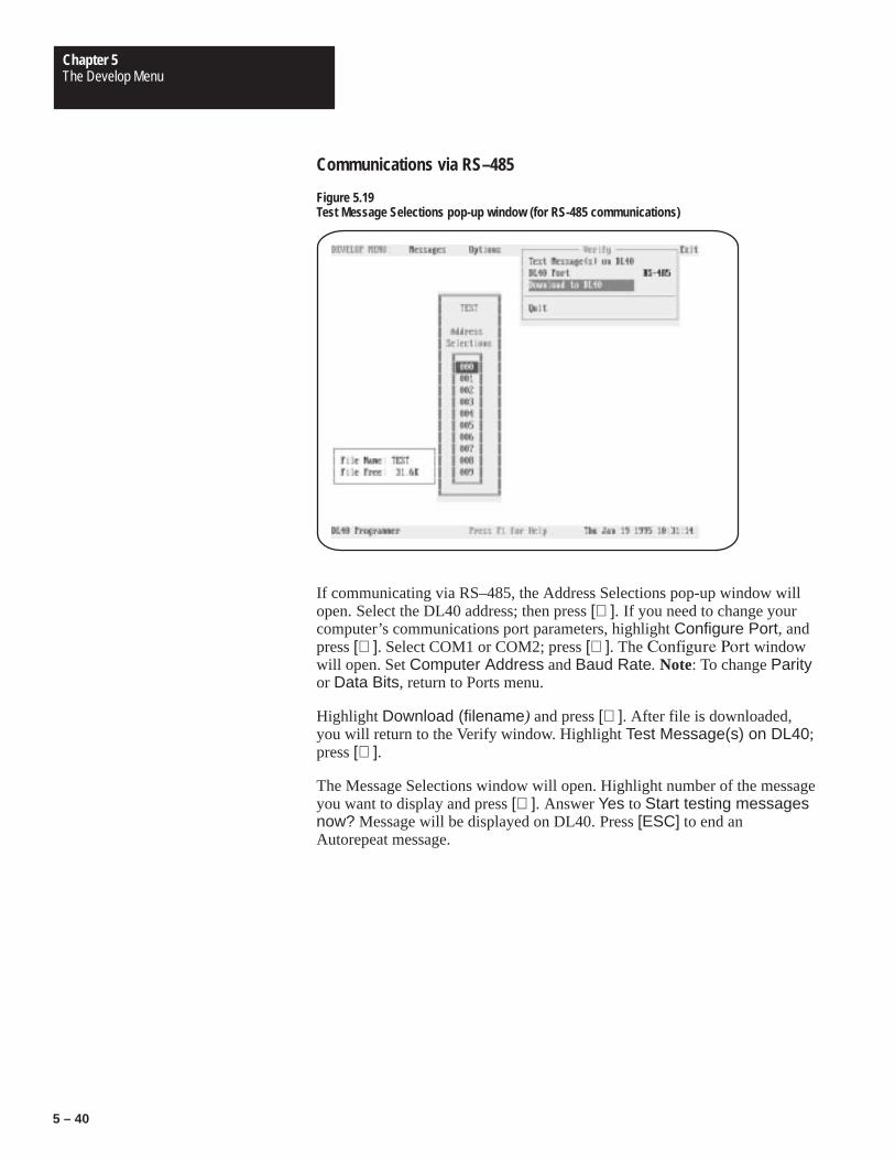
Chapter 5The Develop Menu
5 – 40
Communications via RS–485
Figure 5.19Test Message Selections pop-up window (for RS-485 communications)
If communicating via RS–485, the Address Selections pop-up window willopen. Select the DL40 address; then press [↵ ]. If you need to change yourcomputer’s communications port parameters, highlight Configure Port, andpress [↵ ]. Select COM1 or COM2; press [↵ ]. The ������� �� windowwill open. Set Computer Address and Baud Rate. Note: To change Parityor Data Bits, return to Ports menu.
Highlight Download (filename) and press [↵ ]. After file is downloaded,you will return to the Verify window. Highlight Test Message(s) on DL40;press [↵ ].
The Message Selections window will open. Highlight number of the messageyou want to display and press [↵ ]. Answer Yes to Start testing messagesnow? Message will be displayed on DL40. Press [ESC] to end anAutorepeat message.

Chapter 5The Develop Menu
5 – 41
Communications via RS–232
Figure 5.20Test Message Selections pop-up window (for RS-232 communications)
Communicating via RS–232, no Address Selection window will open. Tochange your computer’s communications port parameters, highlightConfigure Port; press [↵ ]. Select COM1 or COM2; press [↵ ]. TheConfigure Port window will open. Set Baud Rate. Note: To change Parityor Data Bits, return to the Ports menu.
Highlight Download (filename) and press [↵ ]. After file is downloaded,you will return to the Verify window. Highlight Test Message(s) on DL40and press [↵ ]. Note: Handshake must be set to None. See page 5–4.
The Message Selections window will open. Highlight the number of themessage you want to display and press [↵ ]. Answer Yes to Start testingmessages now? The message will be displayed on the DL40. Press [ESC]to end an Autorepeat message.
If your message contains variables, you must put in a value for the variableswhen testing the message. When you answer Yes to Start testingmessages now?, a message text window and an Enter variable window forthe first variable will open. Enter value for your first variable; press [↵ ]. Thewindow for your second variable will open. Continue to enter values for all[CTRL][W] and [CTRL][W] variables.
Note: Values for [CTRL][X] variables are entered into a message via akeyboard while it is being displayed.
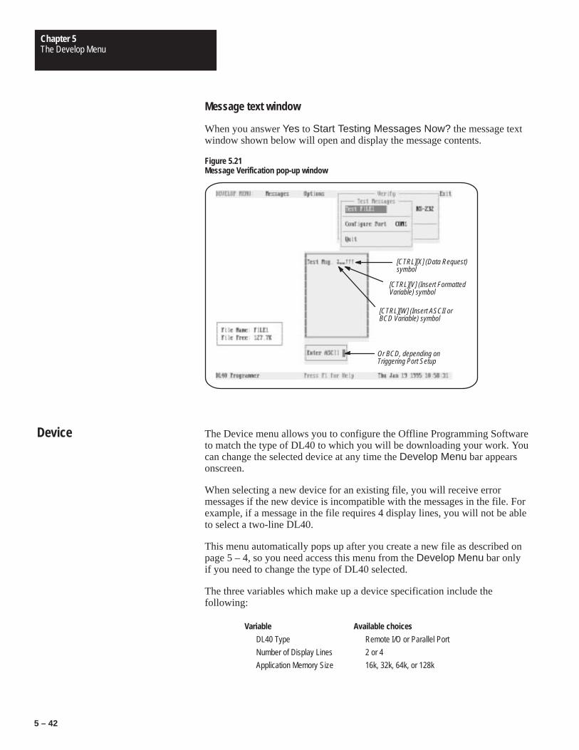
Chapter 5The Develop Menu
5 – 42
Message text window
When you answer Yes to Start Testing Messages Now? the message textwindow shown below will open and display the message contents.
Figure 5.21Message Verification pop-up window
[CTRL][X] (Data Request)symbol
[CTRL][V] (Insert FormattedVariable) symbol
[CTRL][W] (Insert ASCII orBCD Variable) symbol
Or BCD, depending onTriggering Port Setup
The Device menu allows you to configure the Offline Programming Softwareto match the type of DL40 to which you will be downloading your work. Youcan change the selected device at any time the Develop Menu bar appearsonscreen.
When selecting a new device for an existing file, you will receive errormessages if the new device is incompatible with the messages in the file. Forexample, if a message in the file requires 4 display lines, you will not be ableto select a two-line DL40.
This menu automatically pops up after you create a new file as described onpage 5 – 4, so you need access this menu from the Develop Menu bar onlyif you need to change the type of DL40 selected.
The three variables which make up a device specification include thefollowing:
Variable Available choices
DL40 Type Remote I/O or Parallel Port
Number of Display Lines 2 or 4
Application Memory Size 16k, 32k, 64k, or 128k
Device

Chapter 5The Develop Menu
5 – 43
Figure 5.22Device menu
Special keys
You may use the following special keys on this menu.
↑ ↓ Moves the cursor up or down the menu
↵ Lists or accepts choices
Moves cursor to first menu item
Moves cursor directly to Quit
Get Online Help
Closes the menu without taking action.

Chapter
6Chapter 6The Transfer Menu
Figure 6Table 6
6 – 1
Chapter 6
The Transfer Menu
This chapter describes the functions available to you from the Transfer menu.As its name implies, the options available from this menu provide the toolsneeded to move files and data between the Offline Programming Softwareand the devices to which it is connected.
To open the Transfer menu, use the right and left arrow keys to highlightTransfer on the Main menu bar, then press [↵ ]
Selecting Transfer on the Main menu bar will result in display of theTransfer menu.
Figure 6.1Transfer menu top level
Transfer Menu Top Level

Chapter 6The Transfer Menu
6 – 2
Special keys
You may use the following special keys on the Transfer menu or on any ofthe submenus described in this chapter.
↓ ↑ Move the cursor to the desired function
Move the cursor directly to the first menu item
Move the cursor directly to the last menu item (Quit)
↵ Selects the item highlighted by the cursor, opens the next menu, or selectsfrom a pop-up list of options
Closes the menu or screen and returns cursor to the previous menu
Get Online Help
Notes
From the Transfer menu you can perform the following activities:
• download a file to a DL40 using RS-232 or RS-485
• upload a file from a DL40 using RS-232 or RS-485
• download a file to a DL40 using Remote I/O via DH+ or EthernetPassThrough
• upload a file from a DL40 using Remote I/O via DH+ or EthernetPassThrough
• send the time to a DL40 using RS-232 or RS-485
• write a file to a tape recorder
• read a file from a tape recorder
You can transfer one file at a time to or from a DL40 or tape recorder.
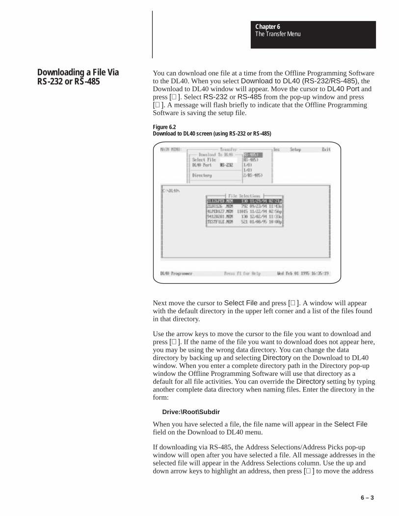
Chapter 6The Transfer Menu
6 – 3
You can download one file at a time from the Offline Programming Softwareto the DL40. When you select Download to DL40 (RS-232/RS-485), theDownload to DL40 window will appear. Move the cursor to DL40 Port andpress [↵ ]. Select RS-232 or RS-485 from the pop-up window and press[↵ ]. A message will flash briefly to indicate that the Offline ProgrammingSoftware is saving the setup file.
Figure 6.2Download to DL40 screen (using RS-232 or RS-485)
Next move the cursor to Select File and press [↵ ]. A window will appearwith the default directory in the upper left corner and a list of the files foundin that directory.
Use the arrow keys to move the cursor to the file you want to download andpress [↵ ]. If the name of the file you want to download does not appear here,you may be using the wrong data directory. You can change the datadirectory by backing up and selecting Directory on the Download to DL40window. When you enter a complete directory path in the Directory pop-upwindow the Offline Programming Software will use that directory as adefault for all file activities. You can override the Directory setting by typinganother complete data directory when naming files. Enter the directory in theform:
Drive:\Root\Subdir
When you have selected a file, the file name will appear in the Select Filefield on the Download to DL40 menu.
If downloading via RS-485, the Address Selections/Address Picks pop-upwindow will open after you have selected a file. All message addresses in theselected file will appear in the Address Selections column. Use the up anddown arrow keys to highlight an address, then press [↵ ] to move the address
Downloading a File ViaRS-232 or RS-485

Chapter 6The Transfer Menu
6 – 4
to the Address Picks column. After you have moved all the addresses to bedownloaded into the Address Picks column, press [F10].
To select a block of addresses, move the cursor to the first address on theblock and press [CTRL][B] to mark the beginning of the block. Then movethe cursor to the last address in the block and press [↵ ]. The entire block willbe moved to the opposite column.
Figure 6.3RS-485 Address Selections/Address Picks window

Chapter 6The Transfer Menu
6 – 5
You may use the following special keys on the Address Selections/AddressPicks window.
← → Moves the cursor to the Address Selections or Address Picks column
↑ ↓ Moves the cursor up or down within a column
↵ Moves the highlighted address from one column to the other
Move the cursor directly to the first item
Move the cursor directly to the last item
Get Online Help
Accept address picks
Closes the Address Selections/Address Picks pop-up without taking action
When you have specified a file and (in the case of an RS-485 download)your desired addresses, the Select File window will open.
The Offline Programming Software allows you to download a completemessage file or only the currently selected file’s parameters. Specify whichyou want by selecting All or Parameters in the Select Download Typefield of the Download to DL40 menu.
Note: To use Verify you must select All in the Select Download Type field.
To configure your computer’s communication port, select Configure Port onthe Download to DL40 menu, then press [↵ ]. Select COM1 or COM2, press[↵ ], and select a baud rate in the Configure Port pop-up window.
Note: To change parity or data bits, return to the Develop→Ports menu.
Important: The software will warn you if the configuration of the DL40 towhich you are writing is different than the configuration of thefile you are downloading. Device type, number of lines, andmemory size must all match.
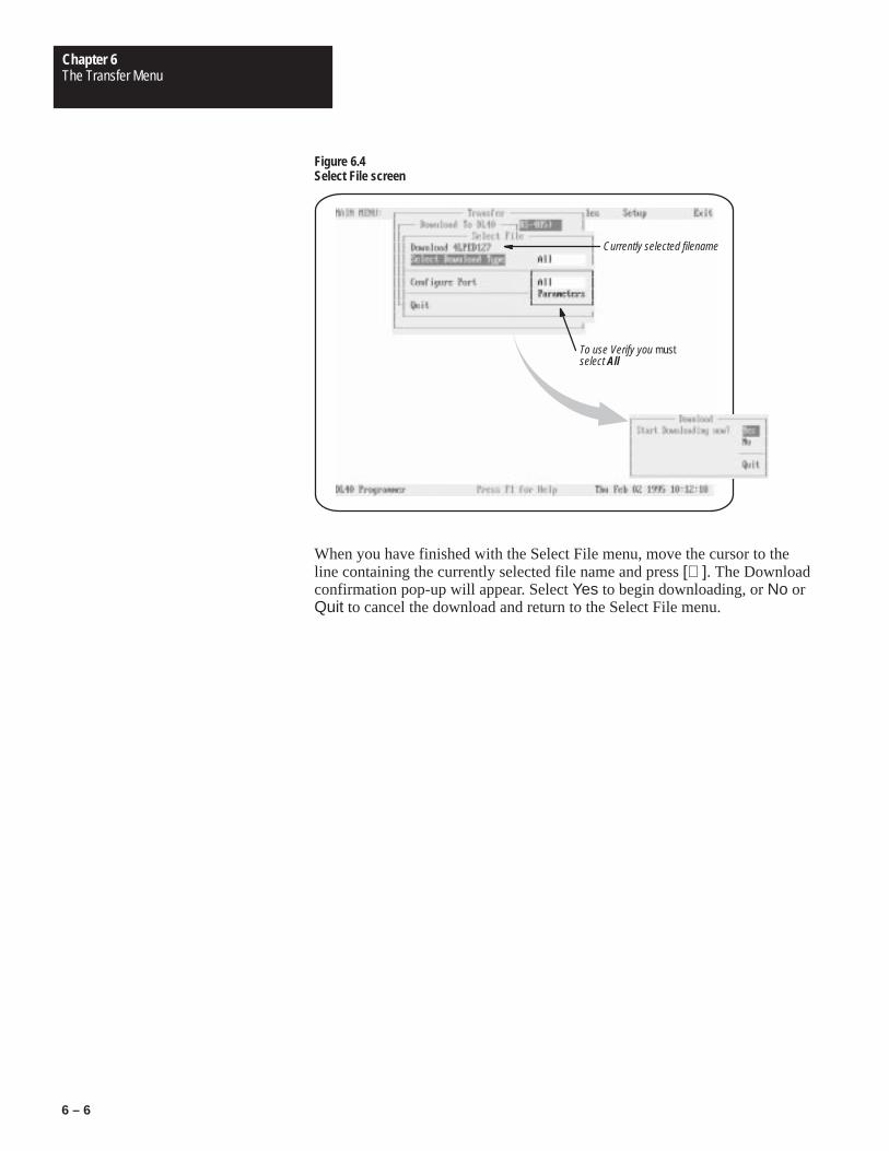
Chapter 6The Transfer Menu
6 – 6
Figure 6.4Select File screen
Currently selected filename
To use Verify you mustselect All
When you have finished with the Select File menu, move the cursor to theline containing the currently selected file name and press [↵ ]. The Downloadconfirmation pop-up will appear. Select Yes to begin downloading, or No orQuit to cancel the download and return to the Select File menu.

Chapter 6The Transfer Menu
6 – 7
You can upload one file at a time from a DL40 to the Offline ProgrammingSoftware. When you select Upload from DL40 (RS-232/RS-485), theUpload File from DL40 window will appear. Move the cursor to DL40 Portand press [↵ ]. Select RS-232 or RS-485 from the pop-up window andpress [↵ ]. A message will flash briefly to indicate that the OfflineProgramming Software is saving the setup file.
Figure 6.5Upload File from DL40 screen (via RS-232)
To configure your computer’s communication port, select Configure Port onthe Upload to DL40 menu, then press [↵ ]. Select COM1 or COM2, press[↵ ], specify your computer’s address (if using RS-485), and select a baudrate in the Configure Port pop-up window.
Note: To change parity or data bits, return to the Develop→Ports menu.
If necessary, you can select Directory to change the currently selected datadirectory for the uploaded files.
Uploading a FileVia RS-232 or RS-485

Chapter 6The Transfer Menu
6 – 8
Figure 6.6Address Selections screen when uploading via RS-485
If uploading via RS-485, the Address Selections pop-up window will openwhen you select Upload File. Use the up and down arrow keys to highlightan address, then press [↵ ] to select the highlighted address and return to theUpload File from DL40 menu.
When you have finished making changes on the Upload File from DL40menu, move the cursor to the line containing the words Upload File andpress [↵ ]. The Upload confirmation pop-up will appear. Select Yes to beginuploading, or No or Quit to cancel the upload and return to the Upload Filefrom DL40 menu.

Chapter 6The Transfer Menu
6 – 9
You can download one file at a time from the Offline Programming Softwareto the DL40. When you select Download to DL40 (Remote I/O) and press[↵ ], the Download (Remote I/O) window will appear.
Important: The DL40 must be operating in Block Transfer mode to useRemote I/O PassThrough.
Figure 6.7Download (Remote I/O) file selection screen
Move the cursor to Select File and press [↵ ]. The program will display abrief message indicating it is searching for data files, then display the FileSelections pop-up window. Use the cursor keys to highlight a file name andpress [↵ ]. When you do so the Message Selections pop-up window will bereplaced by an expanded version of the Download (Remote I/O) window.Included in this window are the be address parameters of the currentlyselected communication (.UDU) file, including DL40 Rack (address), DL40Group (number), and PLC Address. In addition, the window includes theDownload FILENAME item and menu choices allowing you to modify anexisting Communication File or create a new one.
NOTE: There is no default Communication File. You must create at leastone file to upload or download over Remote I/O via DH+ or Ethernet.Procedures for creating a new or modifying an existing Communication Fileappear beginning on page 6 – 13.
Downloading a File ViaRemote I/O (PassThrough)
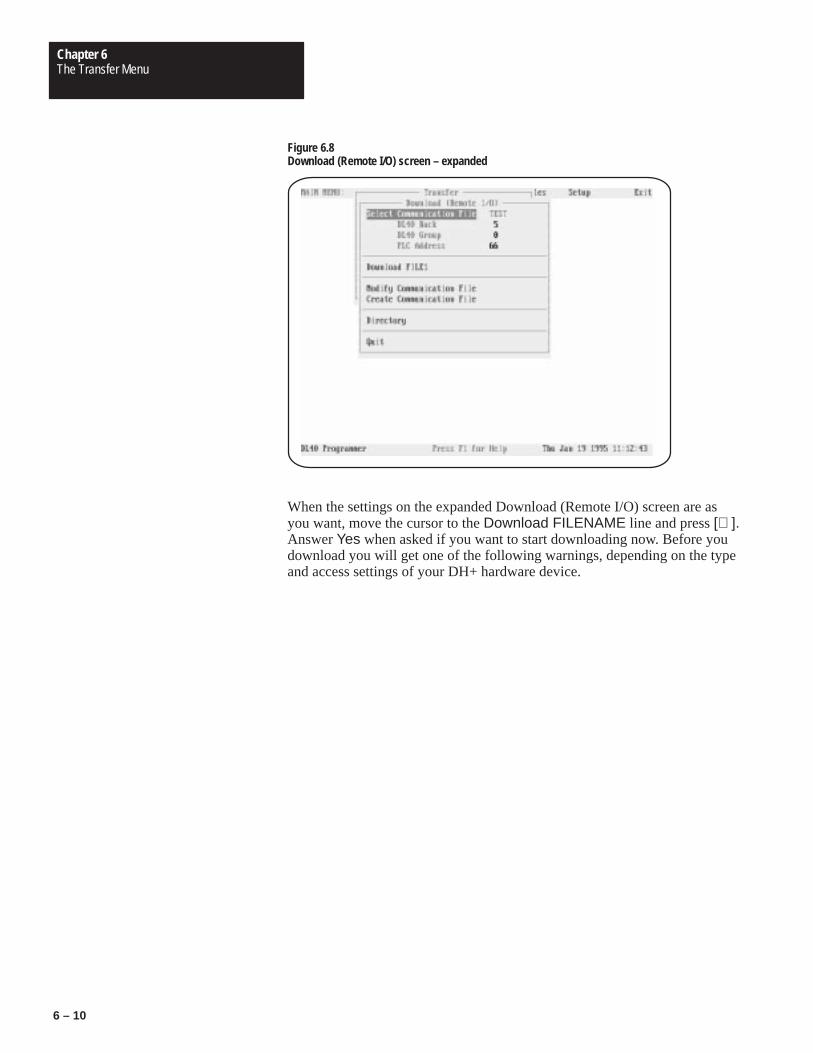
Chapter 6The Transfer Menu
6 – 10
Figure 6.8Download (Remote I/O) screen – expanded
When the settings on the expanded Download (Remote I/O) screen are asyou want, move the cursor to the Download FILENAME line and press [↵ ].Answer Yes when asked if you want to start downloading now. Before youdownload you will get one of the following warnings, depending on the typeand access settings of your DH+ hardware device.

Chapter 6The Transfer Menu
6 – 11
!
ATTENTION: Before the download begins, you will see one ofthe following warnings. Which one you see depends on the typeand access settings of your DH+ or Ethernet hardware device.
WARNING: Incorrect address selection could corrupt data ina non-DL40 device. Verify that the correct CommunicationFile is selected.
WARNING: Incorrect address selection could corrupt data ina non-DL40 device. Verify that the correct CommunicationFile is selected.DH+ Network Access is set to Local.
WARNING: Incorrect address selection could corrupt data ina non-DL40 device. Verify that the correct CommunicationFile is selected.DH+ Network Access is set to Remote (Bridge)
– Local Address is __.– Remote Bridge Address is __.
Be sure the selected communication file has the correctaddress parameters, and change them if necessary beforecontinuing.
NOTE: When downloading via Remote I/O, Download Type isautomatically set to All. You can’t transfer just Parameters.

Chapter 6The Transfer Menu
6 – 12
You can upload one file at a time from the DL40 to the Offline ProgrammingSoftware. When you select Upload to DL40 (Remote I/O), the Upload(Remote I/O) window will appear.
Figure 6.9Upload via Remote I/O screen
Included in this window are the address parameters of the currently selectedcommunication (.UDU) file, including DL40 Rack (address), DL40 Group(number), and PLC Address. In addition, the window includes the UploadFile item and menu choices allowing you to modify an existingCommunication File or create a new one.
NOTE: There is no default Communication File. You must create at leastone file to upload or download over Remote I/O via DH+ or EthernetPassThrough. Procedures for creating a new or modifying an existingCommunication File appear beginning on page 6 – 13.
When the settings on the Upload (Remote I/O) screen are as you want, movethe cursor to the Upload File line and press [↵ ]. Answer Yes when asked ifyou want to start uploading now. Before you upload you will get one of thefollowing warnings, depending on the type and access settings of your DH+hardware device.
Uploading a File ViaRemote I/O (PassThrough)

Chapter 6The Transfer Menu
6 – 13
!
ATTENTION: Before the upload begins, you will see one of thefollowing warnings. Which one you see depends on the type andaccess settings of your DH+ or Ethernet hardware device.
WARNING: Incorrect address selection could corrupt data ina non-DL40 device. Verify that the correct CommunicationFile is selected.
WARNING: Incorrect address selection could corrupt data ina non-DL40 device. Verify that the correct CommunicationFile is selected.DH+ Network Access is set to Local.
WARNING: Incorrect address selection could corrupt data ina non-DL40 device. Verify that the correct CommunicationFile is selected.DH+ Network Access is set to Remote (Bridge)
– Local Address is __.– Remote Bridge Address is __.
Be sure the selected communication file has the correctaddress parameters, and change them if necessary beforecontinuing.
To specify a new Communication File, highlight Create CommunicationFile (in either the Download (Remote I/O) or Upload (Remote I/O) menus)and press [↵ ]. You will be asked to specify a file name. To create a file inanother directory, highlight Directory and press [↵ ] and the Program Datadirectory window will open. Enter the directory in the form:
Drive:\Root\Subdir
Press [↵ ]. The Communication File window will open. Highlight theparameter you want to set and press [↵ ]. Select parameter setting and press[↵ ]. When you highlight Hardware Device and press [↵ ], a pop-upwindow will open from which you can select the hardware device you areusing. Set device parameters.
Creating a NewCommunications File
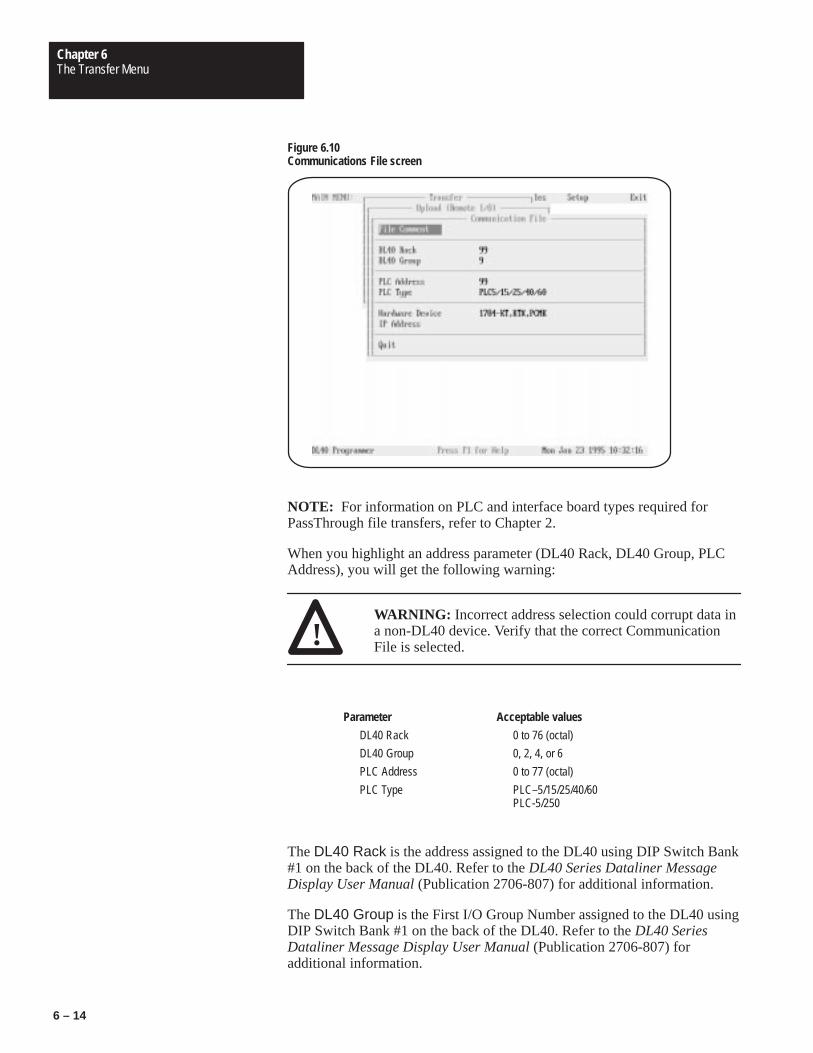
Chapter 6The Transfer Menu
6 – 14
Figure 6.10Communications File screen
NOTE: For information on PLC and interface board types required forPassThrough file transfers, refer to Chapter 2.
When you highlight an address parameter (DL40 Rack, DL40 Group, PLCAddress), you will get the following warning:
!WARNING: Incorrect address selection could corrupt data ina non-DL40 device. Verify that the correct CommunicationFile is selected.
Parameter Acceptable values
DL40 Rack 0 to 76 (octal)
DL40 Group 0, 2, 4, or 6
PLC Address 0 to 77 (octal)
PLC Type PLC–5/15/25/40/60PLC-5/250
The DL40 Rack is the address assigned to the DL40 using DIP Switch Bank#1 on the back of the DL40. Refer to the DL40 Series Dataliner MessageDisplay User Manual (Publication 2706-807) for additional information.
The DL40 Group is the First I/O Group Number assigned to the DL40 usingDIP Switch Bank #1 on the back of the DL40. Refer to the DL40 SeriesDataliner Message Display User Manual (Publication 2706-807) foradditional information.

Chapter 6The Transfer Menu
6 – 15
The PLC Address is the station number of the PLC-5 on the DH+ link towhich the DL40 is attached. This address must match the DIP switch settingson the PLC.
The PLC Type is the type of Allen-Bradley PLC-5 on the DH+ link to whichthe DL40 is attached. Use the PLC-5/250 choice for a PLC mounted in aPyramid Integrator chassis.
Selecting a Hardware Device
As shown below, you can select from a number of hardware devices forperforming PassThrough file transfers.
Figure 6.11Hardware Device pop-up window
Your hardware device choices appear on a pop-up list.
Parameter Acceptable values
Hardware Device 1784-KL①1784-KT, KTX, PCMK①1770-KF2②1784-KT2③ETHERNET
① DH+ Device
② DH+ Device, Serial Interface
③ DH+ Device, Microchannel Bus

Chapter 6The Transfer Menu
6 – 16
If you choose ETHERNET, you must then specify an IP Address in theappropriate field. IP Addresses take the following form:
X.X.X.X
where X is a decimal number from 0 through 255. Consult your networkadministrator to obtain an IP Address.
Setting Device Parameters for a DH+ Network
Additional transfer parameters may be necessary when you select DH+communications devices. For card numbers 1784-KT, 1784-KT2, 1784-KL,1784-KTX, and 1784-PCMK devices, you must specify the DH+Connection Type and DH+ Network Access.
Figure 6.121784-KT, KTX, PCMK configuration screen for DH+ network
Parameter Acceptable values
DH+ Connection Type DirectMultidrop
DH+ Network Access LocalRemote (Bridge)
DH+ Connection Type
Select Direct if your programming computer and your PLC-5 are the onlydevices on the DH+ link, or if there are multiple devices on the link and yourprogramming computer is the first or the last physical device on the link.
Select Multidrop if there are multiple devices on the link and yourprogramming computer is not first or last physical device on the link.

Chapter 6The Transfer Menu
6 – 17
DH+ Network Access
Select Local if the PLC to which the DL40 is attached is on the same DH+link as the programming computer.
Select Remote (Bridge) if the PLC to which the DL40 is attached is on aseparate DH+ link from the DH+ link to which your programming computeris attached, with the two connected by Data Highway.
If you select Remote (Bridge), then you must specify the Local and RemoteBridge Addresses.
Parameter Acceptable values
Local Bridge Address 0 to 376 (octal)
Remote Bridge Address 0 to 376 (octal)
The Local Bridge Address is the Data Highway address that you assign tothe module connecting the DH+ link on which your programming computerresides to the Data Highway. This address must match the settings of the DIPswitches on the module.
The Remote Bridge Address is the Data Highway address that you assignto the module connecting the DH+ link on which the PLC-5 to which theDL40 is connected resides to the Data Highway. This address must match thesettings of the DIP switches on the module.
Setting Device Parameters for an Ethernet Network
Additional transfer parameters may be necessary when you select an Ethernetcommunications device. For Ethernet devices, you must specify the Routing,Pushwheel, and Channel.

Chapter 6The Transfer Menu
6 – 18
Figure 6.13Ethernet Parameters configuration screen
Parameter Acceptable values
Routing PLC 5E5130-RM5130-KA
Pushwheel 1 to 8
Channel 23
Routing
The Routing value will most often be set to a PCL 5E, which indicates thatthe Remote I/O link is attached directly to the PLC being addressed. Choosethe 5130-KA or 5130-RM selections if your are performing transfers via aPLC-5/250 in a Pyramid Integrator chassis.
Pushwheel
A Pushwheel must be specified when the 5130-KA module has beenselected in the Routing field. This value should match the configuration ofthe PLC-5/250.
Channel
You need to specify a Channel if you select either a 5130-KA or 5130-RMmodule. The value in this field should be either 2 or 3 as previously selectedon the PLC-5/250.
After all parameters are set, highlight Quit and press[↵ ].
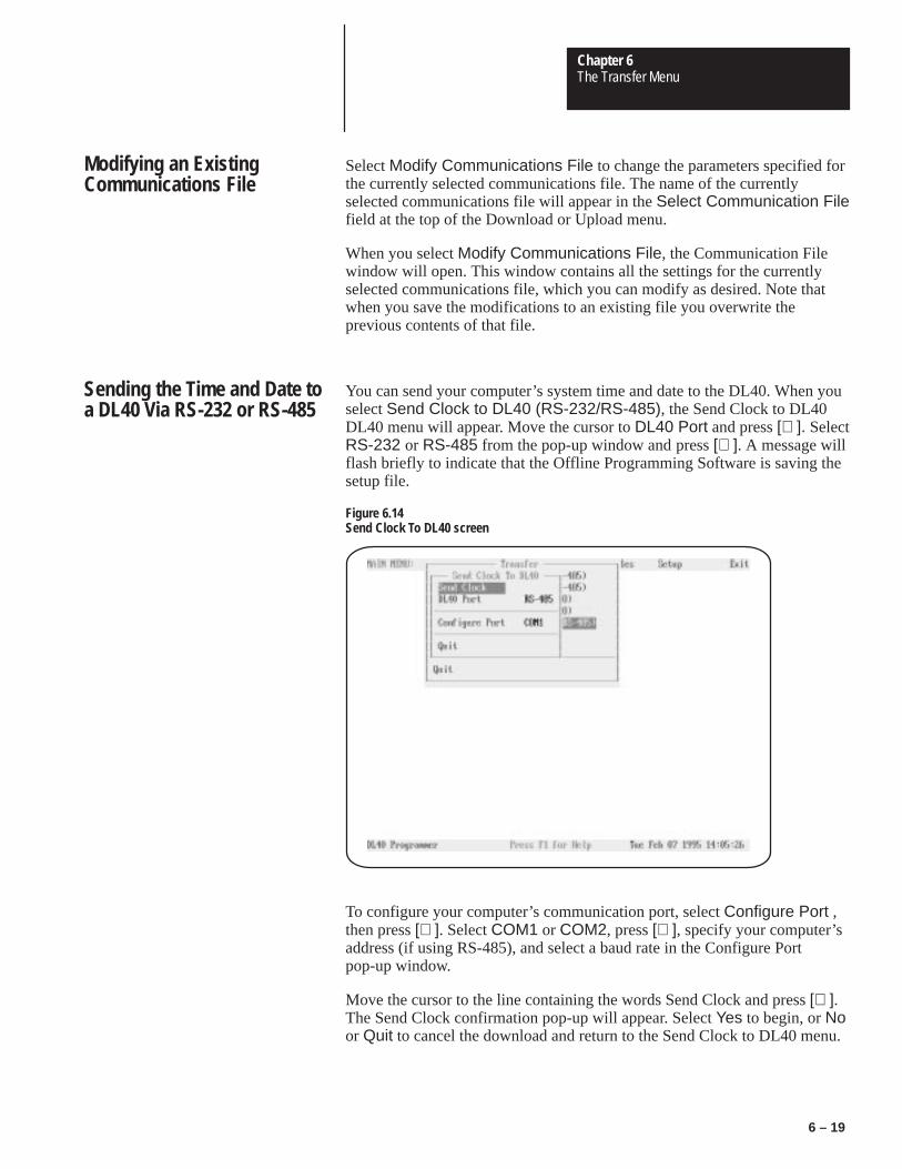
Chapter 6The Transfer Menu
6 – 19
Select Modify Communications File to change the parameters specified forthe currently selected communications file. The name of the currentlyselected communications file will appear in the Select Communication Filefield at the top of the Download or Upload menu.
When you select Modify Communications File, the Communication Filewindow will open. This window contains all the settings for the currentlyselected communications file, which you can modify as desired. Note thatwhen you save the modifications to an existing file you overwrite theprevious contents of that file.
You can send your computer’s system time and date to the DL40. When youselect Send Clock to DL40 (RS-232/RS-485), the Send Clock to DL40DL40 menu will appear. Move the cursor to DL40 Port and press [↵ ]. SelectRS-232 or RS-485 from the pop-up window and press [↵ ]. A message willflash briefly to indicate that the Offline Programming Software is saving thesetup file.
Figure 6.14Send Clock To DL40 screen
To configure your computer’s communication port, select Configure Port ,then press [↵ ]. Select COM1 or COM2, press [↵ ], specify your computer’saddress (if using RS-485), and select a baud rate in the Configure Portpop-up window.
Move the cursor to the line containing the words Send Clock and press [↵ ].The Send Clock confirmation pop-up will appear. Select Yes to begin, or Noor Quit to cancel the download and return to the Send Clock to DL40 menu.
Modifying an ExistingCommunications File
Sending the Time and Date toa DL40 Via RS-232 or RS-485

Chapter 6The Transfer Menu
6 – 20
If using RS-485, the Address Selections/Address Picks pop-up window willopen. All message addresses in the selected file will appear in the AddressSelections column. Use the up and down arrow keys to highlight an address,then press [↵ ] to move the address to the Address Picks column. After youhave moved all the addresses to be updated with new time and date into theAddress Picks column, press [F10].
To select a block of addresses, move the cursor to the first address on theblock and press [CTRL][B] to mark the beginning of the block. Then movethe cursor to the last address in the block and press [↵ ]. The entire block willbe moved to the opposite column.
You can download one file at a time from the Offline Programming Softwareto a tape recorder. When you select Write to Tape Recorder, the Write ToTape window will appear.
Figure 6.15Write To Tape menu
Next move the cursor to Select File and press [↵ ]. The File Selectionswindow will appear with the default directory in the upper left corner and alist of the files found in that directory.
Writing a File to Tape

Chapter 6The Transfer Menu
6 – 21
Figure 6.16File Selections pop-up window
Use the arrow keys to move the cursor to the file you want to download totape and press [↵ ]. If the name of the file you want to download does notappear here, you may be using the wrong data directory. You can change thedata directory by backing up and selecting Directory on the Write To Tapemenu. When you enter a complete directory path in the Directory pop-upwindow the Offline Programming Software will use that directory as adefault for all file activities. You can override the Directory setting by typinganother complete data directory when naming files. Enter the directory in theform:
Drive:\Root\Subdir
When you have selected a file, the wording in the Select File field on theWrite To Tape menu will change to the word Write followed by the file nameyou have selected. The Writing confirmation pop-up will appear. Select Yesto begin, or No or Quit to cancel the download and return to the Select Filemenu.
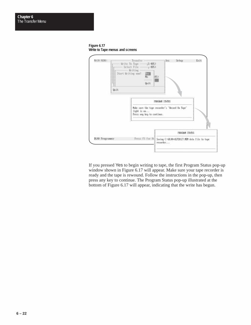
Chapter 6The Transfer Menu
6 – 22
Figure 6.17Write to Tape menus and screens
If you pressed Yes to begin writing to tape, the first Program Status pop-upwindow shown in Figure 6.17 will appear. Make sure your tape recorder isready and the tape is rewound. Follow the instructions in the pop-up, thenpress any key to continue. The Program Status pop-up illustrated at thebottom of Figure 6.17 will appear, indicating that the write has begun.

Chapter 6The Transfer Menu
6 – 23
You can upload one file at a time from a tape recorder to the OfflineProgramming Software. When you select Read From Tape Recorder, theRead From Tape window will appear.
Figure 6.18Read From Tape menus and screens
To configure your computer’s communication port, select Configure Port ,then press [↵ ]. Select COM1 or COM2, press [↵ ], and select a baud rate inthe Configure Port pop-up window.
When you have initiated the upload, the Reading File confirmation pop-upwill appear. Select Yes to begin, or No or Quit to cancel the download andreturn to the Read from Tape menu.
If you pressed Yes to begin reading from tape, the first Program Statuspop-up window shown in Figure 6.18 will appear. Make sure your taperecorder is ready and the tape is rewound. Press the recorder’s READFROM TAPE button, then press any key to continue. The Program Statuspop-up illustrated at the bottom of Figure 6.18 will appear, indicating that thewrite has begun.
After the file is uploaded, the Save Data File As window will open showingthe directory and filename of the uploaded file. You can override thedisplayed data directory by typing another complete data directory whennaming files. Enter the directory in the form:
Drive:\Root\Subdir\Filename
Press [↵ ] to accept the new directory and file name.
Reading a File from Tape

Chapter
7Chapter 7The Reports Menu
Figure 7Table 7
7 – 1
Chapter 7
The Reports Menu
This chapter describes the functions available to you from the Reports menu.As its name implies, the options available from this menu provide the toolsneeded to control the Offline Programming Software’s reporting functions.
To open the Reports menu, use the right and left arrow keys to highlightReports on the Main menu bar, then press [↵ ].
Selecting Reports on the Main menu bar will result in display of the Reportsmenu. You can print one file at a time on your printer.
Highlight Select File, then press [↵ ]. A message will appear brieflyindicating that the software is looking for data files., then the File Selectionswindow will open showing a list of all Message Files found under the currentdirectory. Select the file you want to print, then press [↵ ]. A message willappear briefly indicating that the software is reading the data files, then theSelect File menu will appear.
Figure 7.1Reports menu with File Selections pop–up window
Reports Menu

Chapter 7The Reports Menu
7 – 2
Special keys
You may use the following special keys on the Reports menu or on any of thesubmenus described in this chapter.
↓ ↑ Move the cursor to the desired function
Move the cursor directly to the first menu item
Move the cursor directly to the last menu item (Quit)
↵ Selects the item highlighted by the cursor, opens the next menu, or selectsfrom a pop-up list of options
Closes the menu or screen and returns cursor to the previous menu
Get Online Help
Notes
You can change data path directories by selecting Reports→Directory.When you enter a complete directory path in the resulting pop-up windowthe Offline Programming Software will use that path as a default for all fileactivities. When creating a new data path, specify the path in the form:
Drive:\Directory\Directory1\Directory2
You can change the directory path at any time the Reports menu is displayed.The change will become effective immediately.
In the Select File menu, move the cursor to the Report Type field and press[↵ ]. The Report Type menu will open.
Select File Submenu

Chapter 7The Reports Menu
7 – 3
Figure 7.2Select File menu
Options available to you on the Report Type window include the following:
Parameter Acceptable values
System Attributes Printed Yes or No
All Messages Printed Yes or No
Message Attributes Yes or No
When you have set the Report Type parameters to meet your needs, press[↵ ] to accept your settings and close the Report Type menu.
Choose Configure Port from the Select File and press [↵ ] to identify andconfigure the communication port to which your printer is connected. Apop-up window will appear listing the ports available to you. Use the up anddown arrow keys to select a port and press [↵ ].
Depending on which type of port you select, one of two windows will open.One window allows you to set communication parameters for a COM port,and the other allows you to set the parameters for an LPT port.
The parameters for LPT ports include:
Configure Ports Submenu

Chapter 7The Reports Menu
7 – 4
Parameter Acceptable values
Null Count 0
Page Width 20 to 132
Figure 7.3Configure Ports menus
COM PortConfiguration
LPT PortConfiguration
The parameters for COM ports include:
Parameter Acceptable values
Null Count 0
Page Width 20 to 132
Baud 110. 150, 300, 600, 1200, 2400, 4800, 9600
Parity None, Odd, Even
Data Bits 7 bits, 8 bits
Stop Bits 1 bit, 2 bits
Handshake None, Software, Hardware
When the settings on the Configure Port window meet your needs, press[END] or use the down arrow key to move to the last line of the window andhighlight Quit. Press [↵ ] to close the Configure Port window and return tothe Select File menu.
Check to make sure your printer is properly connected and turned ON. Movethe cursor to the Print FILENAME line on the Select File menu and press[↵ ].
Starting the Print Job

Chapter
8Chapter 8The Files Menu
Figure 8Table 8
8 – 1
Chapter 8
The Files Menu
This chapter describes the functions available to you from the Files menu.On this menu you will find the tools you need to work with application files.
From the File menu you can perform the following activities:
• copy files from one directory to another
• delete files
• rename files
• convert DL20 Message Display application files to make them usablewith a DL40
• change working directories
To open the Files menu, use the right and left arrow keys to highlight Fileson the Main menu bar, then press [↵ ].
Selecting Files on the Main menu bar will result in display of the Filesmenu.
Figure 8.1Files menu top level
Files Menu Top Level

Chapter 8The Files Menu
8 – 2
Special keys
You may use the following special keys on the Files menu or on any of thesubmenus described in this chapter.
↓ ↑ Move the cursor to the desired function or up and down a column in theFile Selections/File Picks window.
← → In the File Selections/File Picks window, moves the cursor from onecolumn to the other
Move the cursor directly to the first menu item
Move the cursor directly to the last menu item (Quit)
↵ Selects the item highlighted by the cursor, opens the next menu, or selectsfrom a pop-up list of options
Closes the menu or screen and returns cursor to the previous menu
Get Online Help
In the File Selections/File Picks window, accepts picks

Chapter 8The Files Menu
8 – 3
Before copying, deleting, renaming, or converting files you must first selectthe files you want to affect. To do so, move the cursor to Select File(s) andpress [↵ ]. The Select File(s) menu will open. From this menu you canchoose to select from a list of:
• DL40 message files only
• communications files only
• all DOS files in the currently selected directory
If necessary, you can select Directory to change the currently selected datapath for the uploaded files.
Highlight one of the menu items and press [↵ ]. The File Selections/FilePicks pop-up window will open.
Figure 8.2Select Files menu
Select Files Menu

Chapter 8The Files Menu
8 – 4
After you have selected the file type you want from the Select File(s) menu,the File Selections/File Picks pop-up window will open. Listed here you willsee all files in the currently selected directory that match the file type youhave specified. Use the up and down arrow keys to highlight a file name,then press [↵ ] to move the file name to the File Picks column. After youhave moved the names of all the files you want to work with into the FilePicks column, press [F10].
To select a block of file names, move the cursor to the first name on theblock and press [CTRL][B] to mark the beginning of the block. Then movethe cursor to the last file name in the block and press [↵ ]. The entire blockwill move to the opposite column.
After you have moved the names of all the files you want to work with intothe File Picks column, press [F10] to accept your selection. The FileSelections/File Picks Column will disappear, and the Files top level menuwill reappear.
Note that you cannot copy, delete, rename, or convert files unless you haveselected at least one file name through the Select File(s) menu. If a selectionis currently in effect, you will see the small File Picks pop-up window in theupper left corner of the screen listing the current selections (as shown inFigure 8.4, for example). The File Picks pop-up will appear only if you haveselected one or more files.
Figure 8.3File Selections/File Picks pop-up window
File Selections/File PicksWindow
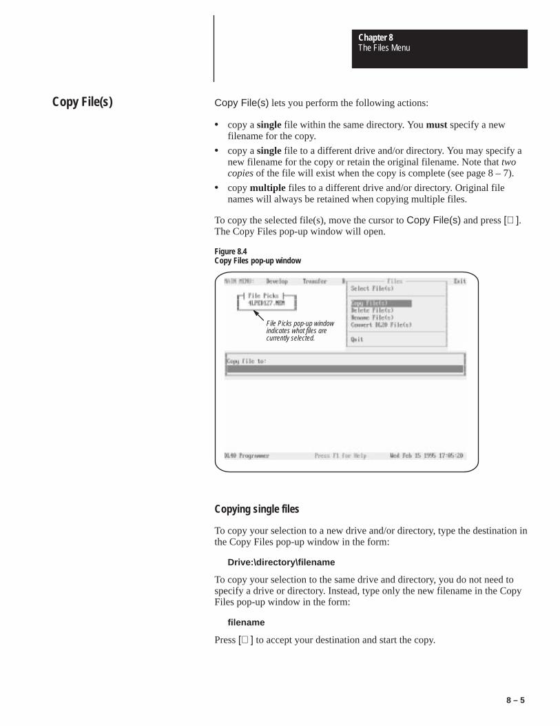
Chapter 8The Files Menu
8 – 5
Copy File(s) lets you perform the following actions:
• copy a single file within the same directory. You must specify a newfilename for the copy.
• copy a single file to a different drive and/or directory. You may specify anew filename for the copy or retain the original filename. Note that twocopies of the file will exist when the copy is complete (see page 8 – 7).
• copy multiple files to a different drive and/or directory. Original filenames will always be retained when copying multiple files.
To copy the selected file(s), move the cursor to Copy File(s) and press [↵ ].The Copy Files pop-up window will open.
Figure 8.4Copy Files pop-up window
File Picks pop-up windowindicates what files arecurrently selected.
Copying single files
To copy your selection to a new drive and/or directory, type the destination inthe Copy Files pop-up window in the form:
Drive:\directory\filename
To copy your selection to the same drive and directory, you do not need tospecify a drive or directory. Instead, type only the new filename in the CopyFiles pop-up window in the form:
filename
Press [↵ ] to accept your destination and start the copy.
Copy File(s)
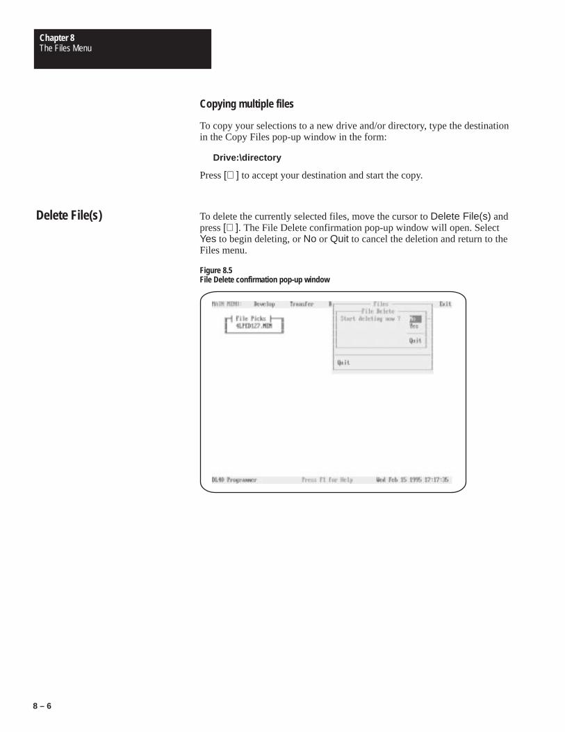
Chapter 8The Files Menu
8 – 6
Copying multiple files
To copy your selections to a new drive and/or directory, type the destinationin the Copy Files pop-up window in the form:
Drive:\directory
Press [↵ ] to accept your destination and start the copy.
To delete the currently selected files, move the cursor to Delete File(s) andpress [↵ ]. The File Delete confirmation pop-up window will open. SelectYes to begin deleting, or No or Quit to cancel the deletion and return to theFiles menu.
Figure 8.5File Delete confirmation pop-up window
Delete File(s)

Chapter 8The Files Menu
8 – 7
Rename File(s) lets you perform the following actions:
• rename a single file within the same directory.
• move a single file to a different drive and/or directory. You may specify anew filename for the copy or retain the original filename. Note that this isa move and not a copy. Only a single copy of the file will exist when themove is complete (See page 8 – 5).
• move multiple files to a different drive and/or directory. Original filenames will always be retained when moving multiple files.
To rename or move the selected file(s), move the cursor to Rename File(s)and press [↵ ]. The Rename Files pop-up window will open.
Figure 8.6Rename File pop-up window
Renaming or moving single files
To rename or move your selection to a new drive and/or directory, type thedestination in the Rename Files pop-up window in the form:
Drive:\directory\filename
To rename your selection without moving it type only the new filename inthe Rename Files pop-up window in the form:
filename
Press [↵ ] to accept the new name.
Rename File(s)

Chapter 8The Files Menu
8 – 8
Moving multiple files
To move your selections to a new drive and/or directory, type the destinationin the Rename Files pop-up window in the form:
Drive:\directory
Press [↵ ] to accept your destination and move the files.
Convert DL20 File(s) lets you perform the following actions:
• convert a single DL20 S Record file to a DL40 file residing in the originaldirectory. You may specify a new filename or retain the original filename.
• convert a single DL20 S Record file to a different drive and/or directory.You may specify a new filename for the converted file or retain theoriginal filename.
• convert multiple DL20 S Record files to DL40 files. Original file nameswill always be retained, but the file name extension will be changed to.MEM.
To convert the selected file(s), move the cursor to Convert DL20 File(s) andpress [↵ ]. The Conversion Destination File pop-up window will open.
Figure 8.7Conversion Destination File pop-up window
Converting single files
To convert your selection type the conversion destination in the ConversionDestination File pop-up window in the form:
Convert DL20 File(s)
Chapter 8The Files Menu
8 – 9
Drive:\directory\filename
Do not provide a file name extension. The Offline Programming Softwarewill automatically add the extension .MEM to the file name you provide.
To convert your selection without moving it type only the new filename inthe Conversion Destination File pop-up window in the form:
filename
Do not provide a file name extension. The Offline Programming Softwarewill automatically add the extension .MEM to the file name you provide.Press [↵ ] to accept the new name.
Converting multiple files
To convert your selections to a new drive and/or directory, type thedestination in the Conversion Destination Files pop-up window in the form:
Drive:\directory
Do not provide a file name extension. The Offline Programming Softwarewill automatically add the extension .MEM to the file name you provide.Press [↵ ] to accept your destination and move the files.

Appendix
AAppendix AMessage Display Worksheets
Figure ATable A
A – 1
Appendix A
Message Display Worksheets
Use a photocopy of this worksheet to record the message number and contentof the messages you create with the Offline Programming Software. For yourconvenience, we’ve provided worksheets for both two-line and four-lineversions of the DL40.
Two Line Worksheet
MESSAGE NUMBER __________
MESSAGE NUMBER __________
MESSAGE NUMBER __________
MESSAGE NUMBER __________
MESSAGE NUMBER __________
Using the Worksheets

Appendix AMessage Display Worksheets
A – 2
Four Line Worksheet
MESSAGE NUMBER __________
MESSAGE NUMBER __________
MESSAGE NUMBER __________
MESSAGE NUMBER __________

Appendix
BAppendix BCables
Figure BTable B
B – 1
Appendix B
Cables
1
2
3
4
5
6
7
8
9
8
3
2
20
7
6
4
5
22
1
DCD
TXD
DTR
COMDSR
RTS
CTS
RI
RXD
DCD
RXDTXD
DTR
COMDSR
RTS
CTS
RI
ChassisGround
DL40 Serial Port Female DB-9* Connector
Allen-Bradley 1784-T47 Laptop or IBM Compatible Serial Port Female DB-25* Connector
* Gender specified is for the cable connectors.
1
2
3
4
5
6
7
8
9
1
2
3
4
5
6
7
8
9
DCD
TXD
DTR
COMDSR
RTS
CTS
RXD
DCD
RXDTXD
DTR
COMDSR
RTS
CTS
DL40 Serial PortFemaleDB-9* Connector
Allen-Bradley 6121 Computer, 1784-T47 Laptop,1784-T60 or IBM AT Copatible Serial Port Female DB-9* Connector
* Gender specified is for the cable connectors.
2706-NC12
2706-NC13
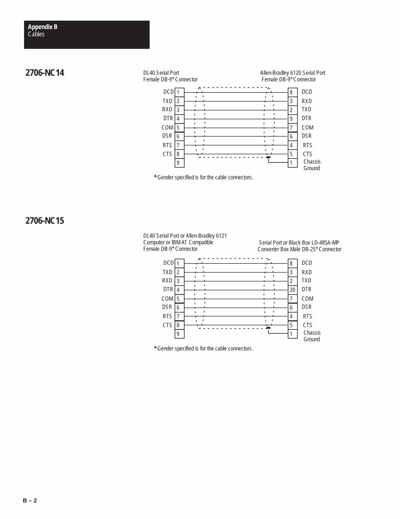
Appendix BCables
B – 2
1
2
3
4
5
6
7
8
9
8
3
2
9
7
6
4
5
1
DCD
TXD
DTR
COMDSR
RTS
CTS
RXD
DCD
RXDTXD
DTR
COMDSR
RTS
CTSChassisGround
DL40 Serial PortFemale DB-9* Connector
Allen-Bradley 6120 Serial Port Female DB-9* Connector
* Gender specified is for the cable connectors.
1
2
3
4
5
6
7
8
9
8
3
2
20
7
6
4
5
1
DCD
TXD
DTR
COMDSR
RTS
CTS
RXD
DCD
RXDTXD
DTR
COMDSR
RTS
CTSChassisGround
DL40 Serial Port or Allen-Bradley 6121Computer or IBM AT CompatibleFemale DB-9* Connector
Serial Port or Black Box LD-485A-MPConverter Box Male DB-25* Connector
* Gender specified is for the cable connectors.
2706-NC14
2706-NC15

Appendix BCables
B – 3
This cable must be assembled by the user.
2
3
5
6
7
8
2
3
7
6
20
5
4
1 ChassisGround
DL40 Serial PortFemale DB-9* Connector
Allen-Bradley 1770-SA or -SB Male DB-25* Connector
* Gender specified is for the cable connectors.
DL40 to Allen-Bradley1770-SA or -SB TapeRecorder

Appendix
CAppendix CExtended ASCII Character Set
Figure CTable C
C – 1
Appendix C
ASCII Character Sets
Standard ASCII Character Set

Appendix CExtended ASCII Character Set
C – 2
Extended ASCII Character SetTo enter an extended ASCII character, use the [ALT] key in combination with thenumeric keypad section on your keyboard. Hold down the [ALT] key, then enterone of the decimal values found in the extended ASCII character chart below.The selected character will appear in the offline message window when yourelease the [ALT] key. Extended ASCII characters are not available with theonboard editor.

Index
Index – 1
Symbols.INI file, 3 – 6.UDU file, 6 – 12[CTRL]F, 5 – 12[CTRL]T, 5 – 14[CTRL]V, 5 – 12[CTRL]W, 5 – 13[CTRL]X, 5 – 13, 5 – 28, 5 – 41[MSG ACK], 5 – 29
AAccessories, 2 – 15Acknowledge message, 5 – 29
and message queueing, 5 – 29Address Selections screen, 6 – 8Address Selections/Address Picks
window, 6 – 4Alarm relay, 2 – 7, 5 – 27All lines, 5 – 30, 5 – 32Archive media, 2 – 5Arrow keys, 5 – 4ASCII data, 2 – 5
request for, 5 – 13word length, 5 – 13
ASCII variable, insert, 5 – 13Attributes, priority of, 5 – 30Auto run message #, 5 – 33AutoClear, 5 – 26
with relay, 5 – 27AUTOEXEC.BAT file, 3 – 10AutoRepeat, 5 – 27
and Historical Events Stack,5 – 28
Auxiliary devices, 2 – 7
BBackground message number,
5 – 33Backup media, 2 – 5Bar code data, 2 – 5BCD data, 2 – 8
word length, 5 – 13BCD variable, insert, 5 – 13Binary Coded Decimal data. See
BCD dataBinary data, 2 – 8
Block Transfer Mode, duringdownload, 6 – 9
Buffers, 3 – 2
CCaps Lock key, 2 – 14Catalog numbers, 2 – 14Chain messages, 2 – 8, 5 – 27
with AutoRepeat, 5 – 27Change formatted variable, 5 – 12Changing Message Attributes,
5 – 23, 5 – 31Channel, 6 – 17, 6 – 18Checkdisk command, 3 – 1Clear message automatically,
5 – 26Clock data, 2 – 6Color monitor, 4 – 5Color slave, 5 – 29Communications File screen,
6 – 14Communications parameters,
5 – 36, 6 – 5, 6 – 9, 6 – 12,6 – 19, 6 – 23
Compound variables, 5 – 13CONFIG.SYS file, 3 – 2, 3 – 10Configure Ports menu, 7 – 4Conversion Destination pop-up,
8 – 8Copy (Message), rules governing,
5 – 17Copy (Messages) Screen, 5 – 16Copy Files pop-up, 8 – 5Create New Message, 5 – 15Create New Message screen,
5 – 15Creating a new file, 5 – 4Cursor, 4 – 2
DData mode, 2 – 8Data Path, 5 – 2, 5 – 5Data Path Directory window,
5 – 5Date, 2 – 6
insert in message, 5 – 14
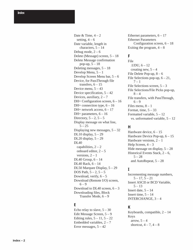
Index
Index – 2
Date & Time, 4 – 2setting, 4 – 6
Date variable, length incharacters, 5 – 14
Debug mode, 2 – 6Delete (Message) screen, 5 – 18Delete Message confirmation
pop-up, 5 – 18Deleting messages, 5 – 18Develop Menu, 5 – 1Develop Screen Menu bar, 5 – 6Device, for PassThrough file
transfers, 6 – 15Device menu, 5 – 43Device specification, 5 – 42Devices, auxiliary, 2 – 7DH+ Configuration screen, 6 – 16DH+ connection type, 6 – 16DH+ network access, 6 – 17DH+ parameters, 6 – 16Directory, 5 – 2, 5 – 5Display message on what line,
5 – 25Displaying new messages, 5 – 32DL10 display, 5 – 29DL20 display, 5 – 29DL40
capabilities, 2 – 2onboard editor, 2 – 5versions, 2 – 1
DL40 Group, 6 – 14DL40 Rack, 6 – 14DL50 Marquee Display, 5 – 29DOS Path, 5 – 2, 5 – 5Download, verify, 6 – 5Download (Remote I/O) screen,
6 – 9Download to DL40 screen, 6 – 3Downloading files, Block
Transfer Mode, 6 – 9
EEcho relay to slave, 5 – 30Edit Message Screen, 5 – 9Editing rules, 5 – 11, 5 – 22Embedded variables, 2 – 7Error messages, 5 – 42
Ethernet parameters, 6 – 17Ethernet Parameters
Configuration screen, 6 – 18Exiting the program, 4 – 8
FFile
.UDU, 6 – 12creating new, 5 – 4
File Delete Pop-up, 8 – 6File Selections pop-up, 6 – 21,
7 – 1File Selections screen, 5 – 3File Selections/File Picks pop-up,
8 – 4File transfers, with PassThrough,
6 – 9Files menu, 8 – 1Format, time, 5 – 33Formatted variable, 5 – 12
vs. unformatted variable, 5 – 12
HHardware device, 6 – 15Hardware Device Pop-up, 6 – 15Hardware versions, 2 – 1Help Screen, 4 – 3Hide message on display, 5 – 28Historical Events Stack, 2 – 6,
5 – 28and AutoRepeat, 5 – 28
IIncrementing message numbers,
5 – 17, 5 – 21Insert ASCII or BCD Variable,
5 – 13Insert date, 5 – 14Insert time, 5 – 14INTERCHANGE, 3 – 4
KKeyboards, compatible, 2 – 14Keys
arrow, 5 – 4shortcut, 4 – 7, 4 – 8

Index
Index – 3
special, 4 – 7, 5 – 11, 5 – 22
LLine usage, 5 – 30, 5 – 32Line usage setting, 5 – 14, 5 – 15Local Bridge, 6 – 17
MMain Menu bar, 4 – 2Main screen, 4 – 2Manual contents, 1 – 1Marquee Display, 5 – 29MEM command, 3 – 2MEMMAKER command, 3 – 3Memory, management of, 3 – 2Menu
Configure Ports, 7 – 4Develop, 5 – 1Device, 5 – 43Files, 8 – 1Messages, 5 – 8Options, 5 – 34Ports, 5 – 35Read From Tape, 6 – 23Reports, 7 – 1Select File, 7 – 3Select Files, 8 – 3Setup, 4 – 4Transfer, 6 – 1Verify, 5 – 39Write to Tape, 6 – 20
Menu barDevelop Screen, 5 – 6Main Menu, 4 – 2
Menu choice, 4 – 2Menu Title, 4 – 2Message
sending to stack, 5 – 28System Attribute Warning, 5 – 8
Message Attribute Defaults,5 – 31
Message Attribute Defaultsscreen, 5 – 31
Message Attribute pop-up, 5 – 23Message attributes
defined, 5 – 25for new messages, 5 – 15
priority of, 5 – 30with variables, 5 – 14
Message chaining, 2 – 8, 5 – 27disabled with AutoRepeat,
5 – 27Message number
assigned during copy, 5 – 16,5 – 19
background, 5 – 33duplicate, 5 – 15, 5 – 17
Message Queueing, 5 – 33Message Selection/Message Picks
Pop-up, 5 – 16, 5 – 18,5 – 19, 5 – 21, 5 – 23, 5 – 31
Message Selections, 5 – 16,5 – 18, 5 – 19, 5 – 21, 5 – 23,5 – 31
Message Selections pop-up, 5 – 9Message Selections/Message
Picks Pop-up, 5 – 20Message Selections/Message
Picks pop-up, 5 – 16Message Text window, 5 – 10,
5 – 15Message time, sending to stack,
5 – 28Message Verification pop-up,
5 – 42Messages
copying, 5 – 16deleting, 5 – 18error, 5 – 42incrementing numbers, 5 – 17,
5 – 21memory, 3 – 1renumbering, 5 – 19selecting multiple, 5 – 17,
5 – 19, 5 – 20, 5 – 31,5 – 32
special, 2 – 12too many messages, 5 – 15,
5 – 17Messages Menu, 5 – 8Modify Message Attributes
screen, 5 – 24Monitor type, 4 – 5Monochrome monitor, 4 – 5Multidrop Mode, 6 – 16

Index
Index – 4
NNew messages, 5 – 32
message attributes with, 5 – 15Num Lock key, 2 – 14
OOnboard editor, 2 – 5, 5 – 29,
5 – 30, 5 – 31, 5 – 32Options menu, 5 – 34
PParallel port units, 5 – 37Parameters
communication, 6 – 5communications, 6 – 9, 6 – 12,
6 – 19, 6 – 23for DH+ PassThrough file
transfers, 6 – 16PassThrough file transfers, 2 – 3,
6 – 9PATH, 5 – 2, 5 – 5PLC Address, 6 – 15PLC Type, 6 – 15PLC-5, with DH+, 6 – 17PLC-5/250, with Ethernet, 6 – 18Pop-up
Address Selections/AddressPicks, 6 – 4
Conversion Destination, 8 – 8Copy Files, 8 – 5Create New File, 5 – 4Data Path Directory, 5 – 5Delete Message confirmation,
5 – 18File Delete, 8 – 6File Selections, 6 – 21, 7 – 1File Selections/File Picks, 8 – 4Hardware Device, 6 – 15Message Selections, 5 – 9Message Selections/Message
Picks, 5 – 16, 5 – 20Message Verification, 5 – 42Rename File, 8 – 7Start/Increment, 5 – 16Text Message Selections
RS-232, 5 – 41RS-485, 5 – 40
Port settingsfor slave display, 5 – 26RS-232, 5 – 36RS-485, 5 – 36triggering, 5 – 37
Ports, report configuration, 7 – 3Ports menu, 5 – 35Print message, 5 – 25Printer port settings, RS-232,
5 – 36Printers, 2 – 7Priority of message attributes,
5 – 30Prompt, underscore, 5 – 28Pushwheel, 6 – 17, 6 – 18
QQueue, enabling, 5 – 33Quitting the program, 4 – 8
RRead From Tape menus &
screens, 6 – 23Relay, 5 – 27
echo to slave, 5 – 30with AutoClear, 5 – 27
Remote (Bridge), 6 – 17Remote I/O units, 5 – 37
and Auto Run, 5 – 33Rename File pop-up, 8 – 7Renumber (Message), rules
governing, 5 – 21Renumber (Messages) screen,
5 – 20Renumbering messages, 5 – 19Repeat message, 5 – 26Repeat message automatically,
5 – 27Repeating messages, 5 – 27Reports, type, 7 – 3Reports menu, 7 – 1Request for ASCII data, 5 – 13Requirements
hardware, 3 – 1memory, 3 – 1
Routing, 6 – 17, 6 – 18

Index
Index – 5
RS-232, testing messages via,5 – 41
RS-232 port settings, 5 – 36RS-232 printer port settings,
5 – 36RS-232 tape recorder settings,
5 – 37RS-485, testing messages via,
5 – 40RS-485 port settings, 5 – 36Run Mode, 5 – 32Run modes, 2 – 9–2 – 12
SScreen
Address Selections, 6 – 8Communications File, 6 – 14Copy (Messages), 5 – 16Create New Message, 5 – 15Delete (Message), 5 – 18Delete (Messages), 5 – 18DH+ Configuration, 6 – 16Download (Remote I/O), 6 – 9Download to DL40, 6 – 3Edit Message, 5 – 9Ethernet Parameters
Configuration, 6 – 18File Selections, 5 – 3Main, 4 – 2Message Attribute Defaults,
5 – 31Modify Message Attributes,
5 – 23, 5 – 24, 5 – 31Read From Tape, 6 – 23Renumber (Messages), 5 – 19,
5 – 20Select File, 6 – 6Send Clock to DL40, 6 – 19Text Search, 5 – 21, 5 – 22Upload File from DL40, 6 – 7Upload Via Remote I/O, 6 – 12
Scroll message, 5 – 25, 5 – 26Searching for text, 5 – 21Select File menu, 7 – 3Select File screen, 6 – 6Select Files menu, 8 – 3
Selecting a block of messages,5 – 17, 5 – 19, 5 – 20, 5 – 31,5 – 32
Send Clock to DL40 screen,6 – 19
Send message time to the stack,5 – 28
Send message to slave, 5 – 26Send message to the stack, 5 – 28Setting time & date, 4 – 6Settings, communications, 5 – 36Setup Menu, 4 – 4Shortcut keys, 4 – 7, 4 – 8Slave, echo relay to, 5 – 30Slave devices, 5 – 36Slave display, 2 – 7, 5 – 29
Port settings for, 5 – 26Slave message color, 5 – 29Slave message length, 5 – 29Special keys, 4 – 7, 5 – 11, 5 – 22Special messages, 2 – 12, 5 – 33Specifying a device, 5 – 42Stack
Historical Events, 5 – 28sending message time to, 5 – 28
Stacks, 3 – 2Start number of special messages,
5 – 33Start/Increment pop-up, 5 – 16System Attribute Warning
message, 5 – 8
TTape recorder, RS-232 port
settings, 5 – 37TCP/IP, 3 – 9Testing messages
via RS–485, 5 – 40via RS-232, 5 – 41
Text Message Selections pop-upRS-232, 5 – 41RS-485, 5 – 40
Text Search screen, 5 – 22Time, 2 – 6
insert in message, 5 – 14

Index
Index – 6
Time & Date, setting, 4 – 6Time format, 5 – 33Time variable, length in
characters, 5 – 14Transfer menu, 6 – 1Triggering port settings, 5 – 37
UUnderscore prompt, 5 – 28Upload File from DL40 screen,
6 – 7Upload Via Remote I/O screen,
6 – 12
VVariable, formatted, 5 – 12
Variable data, message attributeswith, 5 – 14
Variables, 5 – 12compound, 5 – 13embedded, 2 – 7
Verify, during download, 6 – 5Verify menu, 5 – 39
WWait time for message, 5 – 26Window
Create New File, 5 – 4Data Path Directory, 5 – 5Message Text, 5 – 10, 5 – 15
Word length, ASCII or BCD data,5 – 13
Write to Tape menu, 6 – 20

DL20 EDIT COMMANDS
FunctionKeys Pressed
(Simultaneously)
Forward One Space Ctrl [L]
Back One Space Ctrl [H]
Up a Line(Move 20 characters to left within message)
Ctrl [K]
Down a Line(Move 20 characters to right within message)
Ctrl [J]
Delete a Character Ctrl [D]
Change or Review Message Attributes Ctrl [A]
Run Message Ctrl [R]
Erase Message Ctrl [E]
Toggle Uppercase Lock Ctrl [U]
Show Free Memory Ctrl [F]
Imbed Non-Decimal Point Variable Ctrl [V]
Imbed Formatted Decimal Point Variable Ctrl [X]
Change Variable Format Ctrl [C]
Imbed time and Date Ctrl [T]
Show Edit Commands Ctrl [S]
Quit Edit Ctrl [Q]

2
Rockwell Automation helps its customers receive a superior return on their investment by bringingtogether leading brands in industrial automation, creating a broad spectrum of easy-to-integrateproducts. These are supported by local technical resources available worldwide, a global networkof system solutions providers, and the advanced technology resources of Rockwell.
Worldwide representation.
Argentina • Australia • Austria • Bahrain • Belgium • Bolivia • Brazil • Bulgaria • Canada • Chile • China, People’s Republic of • Colombia • Costa Rica • Croatia • CyprusCzech Republic • Denmark • Dominican Republic • Ecuador • Egypt • El Salvador • Finland • France • Germany • Ghana • Greece • Guatemala • Honduras • Hong KongHungary • Iceland • India • Indonesia • Iran • Ireland • Israel • Italy • Jamaica • Japan • Jordan • Korea • Kuwait • Lebanon • Macau • Malaysia • Malta • Mexico • MoroccoThe Netherlands • New Zealand • Nigeria • Norway • Oman • Pakistan • Panama • Peru • Philippines • Poland • Portugal • Puerto Rico • Qatar • Romania • Russia • SaudiArabia • Singapore • Slovakia • Slovenia • South Africa, Republic of • Spain • Sweden • Switzerland • Taiwan • Thailand • Trinidad • Tunisia • Turkey • United Arab EmiratesUnited Kingdom • United States • Uruguay • Venezuela
Rockwell Automation Headquarters, 1201 South Second Street, Milwaukee, WI 53204-2496 USA, Tel: (1) 414 382-2000 Fax: (1) 414 382-4444Rockwell Automation European Headquarters, Avenue Hermann Debroux, 46, 1160 Brussels, Belgium, Tel: (32) 2 663 06 00, Fax: (32) 2 663 06 40Rockwell Automation Asia Pacific Headquarters, 27/F Citicorp Centre, 18 Whitfield Road, Causeway Bay, Hong Kong, Tel: (852) 2887 4788, Fax: (852) 2508 1846World Wide Web: http://www.ab.com
Publication 2706-808 – July 1995Supersedes Catalog Number 2706-ND002, Series B
Supersedes Catalog Number 2706-ND003, Series B
40061-277-01(A)Copyright 1995 Allen-Bradley Company, Inc. Printed in USA