28 9781587202438 appb.qxp 9/1/10 11:49 am page...
TRANSCRIPT
28_9781587202438_appb.qxp 9/1/10 11:49 AM Page 432
Note: Coverage of this topic should be integrated into your study of Chapter 11,“Multilayer Switching,” right before the section “Multilayer Switching with CEF.”
APPENDIX B
SWITCH Exam Updates: Version 1.1
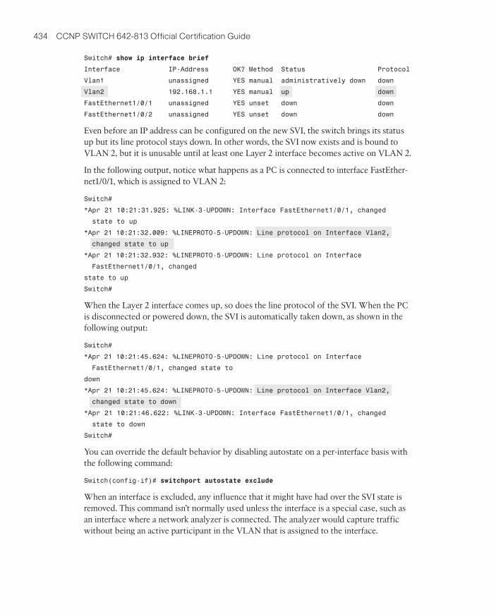
Controlling the Automatic State of an SVIBecause a Layer 3 SVI is bound to a Layer 2 VLAN on a switch, it normally follows thestate of the VLAN on that switch automatically. If the switch has at least one Layer 2interface that is up and active on the VLAN, the Layer 3 SVI will be brought up, too. Ifall the Layer 2 interfaces assigned to the VLAN are down, the Layer 3 interface will bebrought down.
This is the default “autostate” behavior. The idea is to bring the Layer 3 interface downso that routing protocols will cease advertising a route to the IP subnet if no activeswitch interfaces exist on the VLAN where the subnet exists.
When the SVI autostate feature is enabled, a Layer 3 SVI can come up only if the fol-lowing three conditions are met:
■ The VLAN bound to the SVI exists and is active in the VLAN database on the switch
■ The SVI is not administratively shut down
■ At least one Layer 2 interface is assigned to the SVI’s VLAN and is in the up state,with STP forwarding
As an example, a switch has VLAN 2 defined and assigned to a variety of Layer 2 inter-faces, but none of the interfaces are up. A Layer 3 SVI called interface vlan2 is then de-fined. Watch what happens to interface vlan2 in the following console output:
Switch(config)#interface vlan2
Switch(config-if)#
*Apr 21 10:13:10.949: %LINK-3-UPDOWN: Interface Vlan2, changed state to up
Switch(config-if)#
Switch(config-if)#ip address 192.168.1.1 255.255.255.0
Switch(config-if)#^Z
Switch#
28_9781587202438_appb.qxp 9/1/10 11:49 AM Page 433
434 CCNP SWITCH 642-813 Official Certification Guide
Switch# show ip interface brief
Interface IP-Address OK? Method Status Protocol
Vlan1 unassigned YES manual administratively down down
Vlan2 192.168.1.1 YES manual up down
FastEthernet1/0/1 unassigned YES unset down down
FastEthernet1/0/2 unassigned YES unset down down
Even before an IP address can be configured on the new SVI, the switch brings its statusup but its line protocol stays down. In other words, the SVI now exists and is bound toVLAN 2, but it is unusable until at least one Layer 2 interface becomes active on VLAN 2.
In the following output, notice what happens as a PC is connected to interface FastEther-net1/0/1, which is assigned to VLAN 2:
Switch#
*Apr 21 10:21:31.925: %LINK-3-UPDOWN: Interface FastEthernet1/0/1, changed
state to up
*Apr 21 10:21:32.009: %LINEPROTO-5-UPDOWN: Line protocol on Interface Vlan2,
changed state to up
*Apr 21 10:21:32.932: %LINEPROTO-5-UPDOWN: Line protocol on Interface
FastEthernet1/0/1, changed
state to up
Switch#
When the Layer 2 interface comes up, so does the line protocol of the SVI. When the PCis disconnected or powered down, the SVI is automatically taken down, as shown in thefollowing output:
Switch#
*Apr 21 10:21:45.624: %LINEPROTO-5-UPDOWN: Line protocol on Interface
FastEthernet1/0/1, changed state to
down
*Apr 21 10:21:45.624: %LINEPROTO-5-UPDOWN: Line protocol on Interface Vlan2,
changed state to down
*Apr 21 10:21:46.622: %LINK-3-UPDOWN: Interface FastEthernet1/0/1, changed
state to down
Switch#
You can override the default behavior by disabling autostate on a per-interface basis withthe following command:
Switch(config-if)# switchport autostate exclude
When an interface is excluded, any influence that it might have had over the SVI state isremoved. This command isn’t normally used unless the interface is a special case, such asan interface where a network analyzer is connected. The analyzer would capture trafficwithout being an active participant in the VLAN that is assigned to the interface.
28_9781587202438_appb.qxp 9/1/10 11:49 AM Page 434
Appendix B: SWITCH Exam Updates: Version 1.1 435
Note: Coverage of these topics should be integrated into your study of Chapter 13,“Layer 3 High Availability.”
Monitoring the Network to Maximize AvailabilityYou can (and should) design and implement a highly available network by leveraging manyof the features presented in this book. For example, you can bring up redundant links be-tween switches, redundant gateways between switches, and redundant route processors toprovide as much “uptime” as possible for the end users and mission-critical applications.Once configured, these features are all automatic, requiring no further intervention.
But how will you know when some event occurs to trigger a high availability feature? Sup-pose a redundant link goes down for some reason. If you don’t know about it and aren’table to fix it right away, then you no longer have redundant links to mitigate another fu-ture failure.
This section covers the following three important ways you can monitor the network todetect failures and gather information about switch activity:
■ Syslog messages
■ SNMP
■ IP SLA
Syslog Messages
Catalyst switches can be configured to generate an audit trail of messages describing im-portant events that have occurred. These system message logs (syslog) can then be col-lected and analyzed to determine what has happened, when it happened, and how severethe event was.
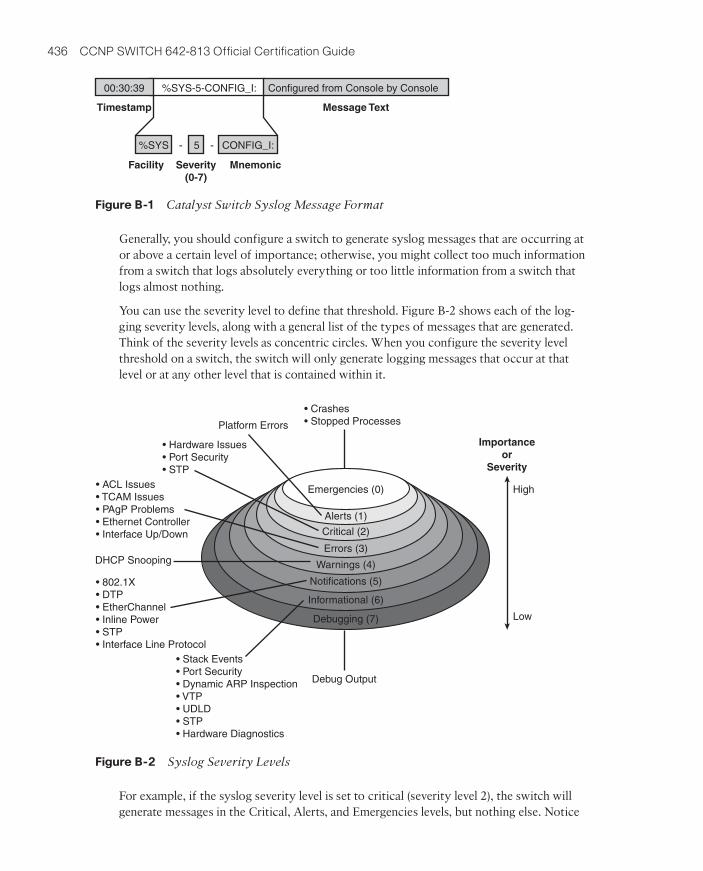
When system messages are generated, they always appear in a consistent format, as shownin Figure B-1. Each message contains the following fields:
■ Timestamp—The date and time from the internal switch clock. By default, theamount of time that the switch has been up is used.
■ Facility Code—A system identifier that categorizes the switch function or modulethat has generated the message; the facility code always begins with a percent sign.
■ Severity—A number from 0 to 7 that indicates how important or severe the event is;a lower severity means the event is more critical.
■ Mnemonic—A short text string that categorizes the event within the facility code.
■ Message Text—A description of the event or condition that triggered the systemmessage.
In Figure B-1, an event in the “System” or SYS facility has triggered the system message.The event is considered to be severity level 5. From the mnemonic CONFIG_I, you can in-fer that something happened with the switch configuration. Indeed, the text descriptionsays that the switch was configured by someone connected to the switch console port.
28_9781587202438_appb.qxp 9/1/10 11:49 AM Page 435
436 CCNP SWITCH 642-813 Official Certification Guide
Generally, you should configure a switch to generate syslog messages that are occurring ator above a certain level of importance; otherwise, you might collect too much informationfrom a switch that logs absolutely everything or too little information from a switch thatlogs almost nothing.
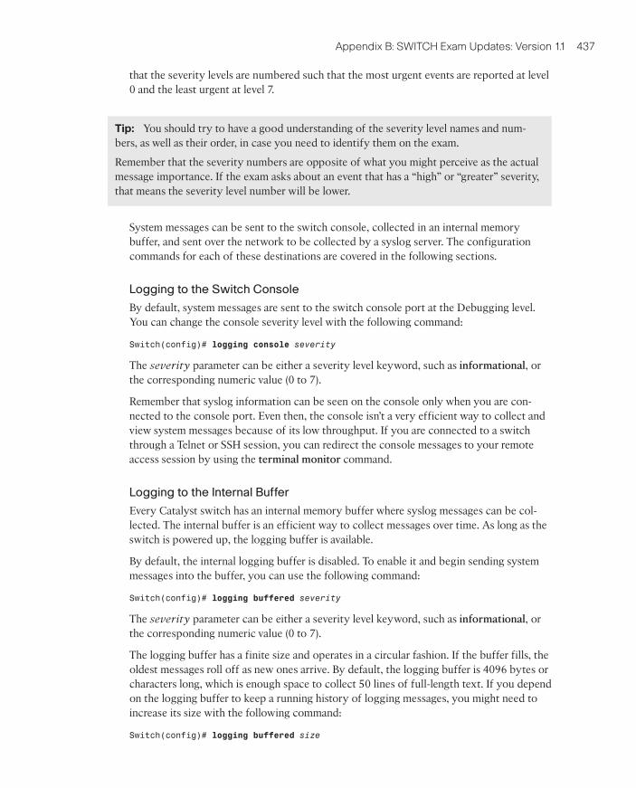
You can use the severity level to define that threshold. Figure B-2 shows each of the log-ging severity levels, along with a general list of the types of messages that are generated.Think of the severity levels as concentric circles. When you configure the severity levelthreshold on a switch, the switch will only generate logging messages that occur at thatlevel or at any other level that is contained within it.
For example, if the syslog severity level is set to critical (severity level 2), the switch willgenerate messages in the Critical, Alerts, and Emergencies levels, but nothing else. Notice
%SYS-5-CONFIG_I:00:30:39
Timestamp
Facility Severity(0-7)
Mnemonic
Message Text
%SYS 5 CONFIG_I:- -
Configured from Console by Console
Figure B-1 Catalyst Switch Syslog Message Format
Platform Errors
Debug Output
DHCP Snooping
• Crashes• Stopped Processes
• Hardware Issues• Port Security• STP
• Stack Events• Port Security• Dynamic ARP Inspection• VTP• UDLD• STP• Hardware Diagnostics
• ACL Issues• TCAM Issues• PAgP Problems• Ethernet Controller• Interface Up/Down
• 802.1X• DTP• EtherChannel• Inline Power• STP• Interface Line Protocol
Importanceor
Severity
Emergencies (0)
Alerts (1)
Critical (2)
Errors (3)
Warnings (4)
Notifications (5)
Informational (6)
Debugging (7)
High
Low
Figure B-2 Syslog Severity Levels
28_9781587202438_appb.qxp 9/1/10 11:49 AM Page 436
Appendix B: SWITCH Exam Updates: Version 1.1 437
that the severity levels are numbered such that the most urgent events are reported at level0 and the least urgent at level 7.
Tip: You should try to have a good understanding of the severity level names and num-bers, as well as their order, in case you need to identify them on the exam.
Remember that the severity numbers are opposite of what you might perceive as the actualmessage importance. If the exam asks about an event that has a “high” or “greater” severity,that means the severity level number will be lower.
System messages can be sent to the switch console, collected in an internal memorybuffer, and sent over the network to be collected by a syslog server. The configurationcommands for each of these destinations are covered in the following sections.
Logging to the Switch Console
By default, system messages are sent to the switch console port at the Debugging level.You can change the console severity level with the following command:
Switch(config)# logging console severity
The severity parameter can be either a severity level keyword, such as informational, orthe corresponding numeric value (0 to 7).
Remember that syslog information can be seen on the console only when you are con-nected to the console port. Even then, the console isn’t a very efficient way to collect andview system messages because of its low throughput. If you are connected to a switchthrough a Telnet or SSH session, you can redirect the console messages to your remote access session by using the terminal monitor command.
Logging to the Internal Buffer
Every Catalyst switch has an internal memory buffer where syslog messages can be col-lected. The internal buffer is an efficient way to collect messages over time. As long as theswitch is powered up, the logging buffer is available.
By default, the internal logging buffer is disabled. To enable it and begin sending systemmessages into the buffer, you can use the following command:
Switch(config)# logging buffered severity
The severity parameter can be either a severity level keyword, such as informational, orthe corresponding numeric value (0 to 7).
The logging buffer has a finite size and operates in a circular fashion. If the buffer fills, theoldest messages roll off as new ones arrive. By default, the logging buffer is 4096 bytes orcharacters long, which is enough space to collect 50 lines of full-length text. If you dependon the logging buffer to keep a running history of logging messages, you might need toincrease its size with the following command:
Switch(config)# logging buffered size
28_9781587202438_appb.qxp 9/1/10 11:49 AM Page 437
438 CCNP SWITCH 642-813 Official Certification Guide
The buffer length is set to size (4096 to 2147483647) bytes. Be careful not to set thelength too big because the switch reserves the logging buffer space from the memory itmight need for other operations.
To review the internal logging buffer at any time, you can use the show logging command.
Logging to a Remote Syslog Server
Syslog servers provide the most robust method of logging message collection. Messagesare sent from a switch to a syslog server over the network using UDP port 514. This meansthat a syslog server can be located anywhere, as long as it is reachable by the switch. Asyslog server can collect logs from many different devices simultaneously and can archivethe logging information for a long period of time.
To identify a syslog server and begin sending logging messages to it, you can use the fol-lowing commands:
Switch(config)# logging host
Switch(config)# logging trap severity
The syslog server is located at hostname or IP address host. You can enter the logging
host command more than once if you have more than one syslog server collecting logginginformation. The syslog server severity level can be either a severity level keyword, such asinformational, or the corresponding numeric value (0 to 7).
Tip: Notice that each of the logging message destinations can have a unique severity levelconfigured. For example, you might collect messages of severity level Debugging into theinternal buffer, while collecting severity level Notifications to a syslog server.
Tip: By default, a switch will generate a system message every time it detects an interfacegoing up or down. That sounds like a good thing, until you realize that the syslog server willbe receiving news of every user powering their PC on and off each day. Each link statechange will generate a message at the Errors (3) severity level, as well as a line protocol statechange at Notifications (5) severity level. To prevent this from happening with Access layerinterfaces where end users are connected, you can use the following interface configurationcommand:Switch(config-if)# no logging event link-status
Adding Timestamps to Syslog Messages
If you are watching system messages appear in real time, it’s obvious what time thoseevents have occurred. However, if you need to review messages that have been collectedand archived in the internal logging buffer or on a syslog server, message timestamps be-come really important.
By default, Catalyst switches add a simple “uptime” timestamp to logging messages. Thisis a cumulative counter that shows the hours, minutes, and seconds since the switch hasbeen booted up. Suppose you find an important event in the logs and you want to know
28_9781587202438_appb.qxp 9/1/10 11:49 AM Page 438
Appendix B: SWITCH Exam Updates: Version 1.1 439
exactly when it occurred. With the uptime timestamp, you would have to backtrack andcompute the time of the event based on how long the switch has been operating.
Even worse, as time goes on, the uptime timestamp becomes more coarse and difficult tointerpret. In the following output, an interface went down 20 weeks and 2 days after theswitch was booted. Someone made a configuration change 21 weeks and 3 days after theswitch booted. At exactly what date and time did that occur? Who knows!
20w2d: %LINK-3-UPDOWN: Interface FastEthernet1/0/27, changed state to down
21w3d: %SYS-5-CONFIG_I: Configured from console by vty0 (172.25.15.246)
Instead, you can configure the switch to add accurate clock-like timestamps that are easilyinterpreted. Sometimes you also will need to correlate events in the logs of several net-work devices. In that case, it’s important to synchronize the clocks (and timestamps)across all those devices.
Don’t assume that a switch already has its internal clock set to the correct date and time.You can use the show clock command to find out, as in the following example:
Switch# show clock
*00:54:09.691 UTC Mon Mar 1 1993
Switch#
Here the clock has been set to its default value, and it’s March 1, 1993! Clearly, that isn’tuseful at all.
You can use the following commands as a guideline to define the time zone and summer(daylight savings) time, and set the clock:
Switch(config)# clock timezone name offset-hours [offset-minutes]
Switch(config)# clock summer-time name date start-month date year hh:mm
end-month day year hh:mm
[offset-minutes]
–OR-
Switch(config)# clock summer-time name recurring [start-week day month
hh:mm end-week day month hh:mm [offset-minutes]
Switch(config)# exit
Switch# clock set hh:mm:ss
In the following example, the switch is configured for the Eastern time zone in the U.S.and the clock is set for 3:23pm. If no other parameters are given with the clock summer-
time recurring command, U.S. daylight savings time is assumed.
Switch(config)# clock timezone EST -5
Switch(config)# clock summer-time EDT recurring
Switch(config)# exit
Switch# clock set 15:23:00
To synchronize the clocks across multiple switches in your network from common,trusted time sources, you should use the Network Time Protocol (NTP). As a simple ex-
28_9781587202438_appb.qxp 9/1/10 11:49 AM Page 439
440 CCNP SWITCH 642-813 Official Certification Guide
ample, the following commands are used to enable NTP and use the NTP server at192.43.244.18 (time.nist.gov) as an authoritative source:
Switch(config)# ntp server 192.43.244.18
After NTP is configured and enabled, you can use the show ntp status command to verifythat the switch clock is synchronized to the NTP server.
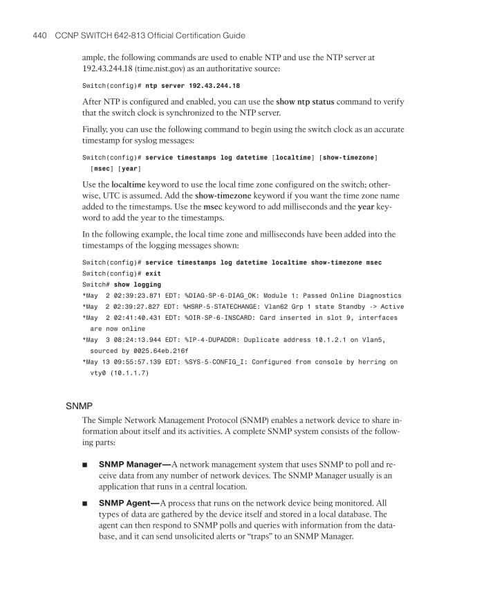
Finally, you can use the following command to begin using the switch clock as an accuratetimestamp for syslog messages:
Switch(config)# service timestamps log datetime [localtime] [show-timezone]
[msec] [year]
Use the localtime keyword to use the local time zone configured on the switch; other-wise, UTC is assumed. Add the show-timezone keyword if you want the time zone nameadded to the timestamps. Use the msec keyword to add milliseconds and the year key-word to add the year to the timestamps.
In the following example, the local time zone and milliseconds have been added into thetimestamps of the logging messages shown:
Switch(config)# service timestamps log datetime localtime show-timezone msec
Switch(config)# exit
Switch# show logging
*May 2 02:39:23.871 EDT: %DIAG-SP-6-DIAG_OK: Module 1: Passed Online Diagnostics
*May 2 02:39:27.827 EDT: %HSRP-5-STATECHANGE: Vlan62 Grp 1 state Standby -> Active
*May 2 02:41:40.431 EDT: %OIR-SP-6-INSCARD: Card inserted in slot 9, interfaces
are now online
*May 3 08:24:13.944 EDT: %IP-4-DUPADDR: Duplicate address 10.1.2.1 on Vlan5,
sourced by 0025.64eb.216f
*May 13 09:55:57.139 EDT: %SYS-5-CONFIG_I: Configured from console by herring on
vty0 (10.1.1.7)
SNMP
The Simple Network Management Protocol (SNMP) enables a network device to share in-formation about itself and its activities. A complete SNMP system consists of the follow-ing parts:
■ SNMP Manager—A network management system that uses SNMP to poll and re-ceive data from any number of network devices. The SNMP Manager usually is anapplication that runs in a central location.
■ SNMP Agent—A process that runs on the network device being monitored. Alltypes of data are gathered by the device itself and stored in a local database. Theagent can then respond to SNMP polls and queries with information from the data-base, and it can send unsolicited alerts or “traps” to an SNMP Manager.
28_9781587202438_appb.qxp 9/1/10 11:49 AM Page 440
Appendix B: SWITCH Exam Updates: Version 1.1 441
In the case of Catalyst switches in the network, each switch automatically collects dataabout itself, its resources, and each of its interfaces. This data is stored in a ManagementInformation Base (MIB) database in memory and is updated in real time.
The MIB is organized in a structured, hierarchical fashion, forming a tree structure. In fact,the entire MIB is really a collection of variables that are stored in individual, more granularMIBs that form the branches of the tree. Each MIB is based on the Abstract Syntax Nota-tion 1 (ASN.1) language. Each variable in the MIB is referenced by an object identifier(OID), which is a long string of concatenated indexes that follow the path from the root ofthe tree all the way to the variable’s location.
Fortunately, only the SNMP manager and agent need to be concerned with interpretingthe MIBs. As far as the SWITCH exam and course go, you should just be aware that theMIB structure exists and that it contains everything about a switch that can be monitored.
To see any of the MIB data, an SNMP manager must send an SNMP poll or query to theswitch. The query contains the OID of the specific variable being requested so that theagent running on the switch knows what information to return. An SNMP manager can usethe following mechanisms to communicate with an SNMP agent, all over UDP port 161:
■ Get Request—The value of one specific MIB variable is needed.
■ Get Next Request—The next or subsequent value following an initial Get Requestis needed.
■ Get Bulk Request—Whole tables or lists of values in a MIB variable are needed.
■ Set Request—A specific MIB variable needs to be set to a value.
SNMP polls or requests are usually sent by the SNMP manager at periodic intervals. Thismakes real-time monitoring difficult because changing variables won’t be noticed until thenext poll cycle. However, SNMP agents can send unsolicited alerts to notify the SNMPmanager of real-time events at any time. Alerts can be sent using the following mecha-nisms over UDP port 162:
■ SNMP Trap—News of an event (interface state change, device failure, and so on) issent without any acknowledgement that the trap has been received.
■ Inform Request—News of an event is sent to an SNMP manager, and the manageris required to acknowledge receipt by echoing the request back to the agent.
As network management has evolved, SNMP has developed into three distinct versions.The original, SNMP version 1 (SNMPv1), is defined in RFC1157. It uses simple one-vari-able Get and Set requests, along with simple SNMP traps. SNMP managers can gain ac-cess to SNMP agents by matching a simple “community” text string. When a managerwants to read or write a MIB variable on a device, it sends the community string in theclear, as part of the request. The request is granted if that community string matches theagent’s community string.
In theory, only managers and agents belonging to the same community should be able tocommunicate. In practice, any device has the potential to read or write variables to anagent’s MIB database by sending the right community string, whether it’s a legitimateSNMP manager or not. This creates a huge security hole in SNMPv1.
28_9781587202438_appb.qxp 9/1/10 11:49 AM Page 441
442 CCNP SWITCH 642-813 Official Certification Guide
The second version of SNMP, SNMPv2C (RFC 1901), was developed to address some effi-ciency and security concerns. For example, SNMPv2c adds 64-bit variable counters, ex-tending the useful range of values over the 32-bit counters used in SNMPv1. In addition,SNMPv2C offers the Bulk Request, making MIB data retrieval more efficient. It also of-fers Inform Requests, which make real-time alerts more reliable by requiring confirmationof receipt.
Despite the intentions of its developers, SNMPv2C does not address any security con-cerns over that of SNMPv1. SNMPv2C does offer 64-bit variable counters, which extendthe capability to keep track of very large numbers, such as byte counters found on high-speed interfaces. With SNMPv2C, MIB variables can be obtained in a bulk form with asingle request. In addition, event notifications sent from an SNMPv2C agent can be in theform of SNMP traps or inform requests. The latter form requires an acknowledgementfrom the SNMP manager that the inform message was received.
The third generation of SNMP, SNMPv3, is defined in RFCs 3410 through 3415. It ad-dresses the security features that are lacking in the earlier versions. SNMPv3 can authenti-cate SNMP managers through usernames. When usernames are configured on the SNMPagent of a switch, they can be organized into SNMPv3 group names.
Each SNMPv3 group is defined with a security level that describes the extent to whichthe SNMP data will be protected. Data packets can be authenticated to preserve their in-tegrity, encrypted to obscure their contents, or both. The following security levels areavailable. The naming scheme uses “auth” to represent packet authentication and “priv” torepresent data privacy or encryption.
■ noAuthNoPriv—SNMP packets are neither authenticated nor encrypted.
■ authNoPriv—SNMP packets are authenticated but not encrypted.
■ authPriv—SNMP packets are authenticated and encrypted.
As a best practice, you should use SNMPv3 to leverage its superior security featureswhenever possible. If you must use SNMPv1 for a device, you should configure the switchto limit SNMP access to a read-only role. Never permit read-write access because the sim-ple community string authentication can be exploited to make unexpected changes to aswitch configuration.
Catalyst switches offer one additional means of limiting SNMP access—an access list canbe configured to permit only specific SNMP manager IP addresses. You should configureand apply an access list to your SNMP configurations whenever possible.
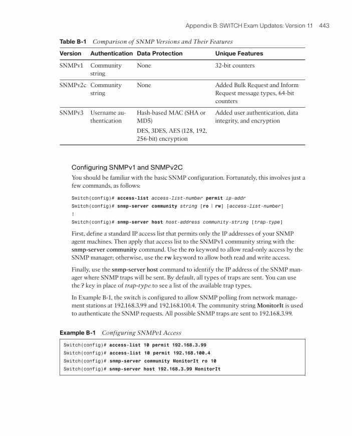
Because SNMP is a universal method for monitoring all sorts of network devices, it isn’tunique to LAN switches. Therefore, you should understand the basics of how SNMPworks, the differences between the different SNMP versions, and how you might applySNMP to monitor a switched network. You can use Table B-1 as a memory aid for yourexam study.
28_9781587202438_appb.qxp 9/1/10 11:49 AM Page 442
Appendix B: SWITCH Exam Updates: Version 1.1 443
Configuring SNMPv1 and SNMPv2C
You should be familiar with the basic SNMP configuration. Fortunately, this involves just afew commands, as follows:
Switch(config)# access-list access-list-number permit ip-addr
Switch(config)# snmp-server community string [ro | rw] [access-list-number]
!
Switch(config)# snmp-server host host-address community-string [trap-type]
First, define a standard IP access list that permits only the IP addresses of your SNMPagent machines. Then apply that access list to the SNMPv1 community string with thesnmp-server community command. Use the ro keyword to allow read-only access by theSNMP manager; otherwise, use the rw keyword to allow both read and write access.
Finally, use the snmp-server host command to identify the IP address of the SNMP man-ager where SNMP traps will be sent. By default, all types of traps are sent. You can usethe ? key in place of trap-type to see a list of the available trap types.
In Example B-1, the switch is configured to allow SNMP polling from network manage-ment stations at 192.168.3.99 and 192.168.100.4. The community string MonitorIt is usedto authenticate the SNMP requests. All possible SNMP traps are sent to 192.168.3.99.
Example B-1 Configuring SNMPv1 Access
Switch(config)# access-list 10 permit 192.168.3.99
Switch(config)# access-list 10 permit 192.168.100.4
Switch(config)# snmp-server community MonitorIt ro 10
Switch(config)# snmp-server host 192.168.3.99 MonitorIt
Table B-1 Comparison of SNMP Versions and Their Features
Version Authentication Data Protection Unique Features
SNMPv1 Communitystring
None 32-bit counters
SNMPv2c Communitystring
None Added Bulk Request and InformRequest message types, 64-bitcounters
SNMPv3 Username au-thentication
Hash-based MAC (SHA orMD5)
DES, 3DES, AES (128, 192,256-bit) encryption
Added user authentication, dataintegrity, and encryption
28_9781587202438_appb.qxp 9/1/10 11:49 AM Page 443
444 CCNP SWITCH 642-813 Official Certification Guide
Configuring SNMPv2C
Configuring SNMPv2C is similar to configuring SNMPv1. The only difference is withSNMP trap or inform configuration. You can use the following commands to configurebasic SNMPv2C operation:
Switch(config)# access-list access-list-number permit ip-addr
Switch(config)# snmp-server community string [ro | rw] [access-list-number]
!
Switch(config)# snmp-server host host-address [informs] version 2c community-string
In the snmp-server host command, use the version 2c keywords to identify SNMPv2Coperation. By default, regular SNMP traps are sent. To use inform requests instead, addthe informs keyword.
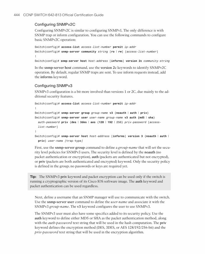
Configuring SNMPv3
SNMPv3 configuration is a bit more involved than versions 1 or 2C, due mainly to the ad-ditional security features.
Switch(config)# access-list access-list-number permit ip-addr
!
Switch(config)# snmp-server group group-name v3 {noauth | auth | priv}
Switch(config)# snmp-server user user-name group-name v3 auth {md5 | sha}
auth-password priv {des | 3des | aes {128 | 192 | 256} priv-password [access-
list-number]
!
Switch(config)# snmp-server host host-address [informs] version 3 {noauth | auth |
priv} user-name [trap-type]
First, use the snmp-server group command to define a group-name that will set the secu-rity level policies for SNMPv3 users. The security level is defined by the noauth (nopacket authentication or encryption), auth (packets are authenticated but not encrypted),or priv (packets are both authenticated and encrypted) keyword. Only the security policyis defined in the group; no passwords or keys are required yet.
Tip: The SNMPv3 priv keyword and packet encryption can be used only if the switch isrunning a cryptographic version of its Cisco IOS software image. The auth keyword andpacket authentication can be used regardless.
Next, define a username that an SNMP manager will use to communicate with the switch.Use the snmp-server user command to define the user-name and associate it with theSNMPv3 group-name. The v3 keyword configures the user to use SNMPv3.
The SNMPv3 user must also have some specifics added to its security policy. Use theauth keyword to define either MD5 or SHA as the packet authentication method, alongwith the auth-password text string that will be used in the hash computation. The priv
keyword defines the encryption method (DES, 3DES, or AES 128/192/256-bit) and thepriv-password text string that will be used in the encryption algorithm.
28_9781587202438_appb.qxp 9/1/10 11:49 AM Page 444
Appendix B: SWITCH Exam Updates: Version 1.1 445
The same SNMPv3 username, authentication method and password, and encryptionmethod and password must also be defined on the SNMP manager so it can successfullytalk to the switch.
Finally, you can use the snmp-server host command to identify the SNMP manager thatwill receive either traps or informs. The switch can use SNMPv3 to send traps and in-forms, using the security parameters that are defined for the SNMPv3 user-name.
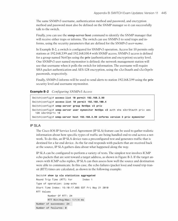
In Example B-2, a switch is configured for SNMPv3 operation. Access list 10 permits onlystations at 192.168.3.99 and 192.168.100.4 with SNMP access. SNMPv3 access is definedfor a group named NetOps using the priv (authentication and encryption) security level.One SNMPv3 user named mymonitor is defined; the network management station willuse that username when it polls the switch for information. The username will requireSHA packet authentication and AES-128 encryption, using the s3cr3tauth and s3cr3tpr1vpasswords, respectively.
Finally, SNMPv3 informs will be used to send alerts to station 192.168.3.99 using the priv
security level and username mymonitor.
Example B-2 Configuring SNMPv3 Access
Switch(config)# access-list 10 permit 192.168.3.99
Switch(config)# access-list 10 permit 192.168.100.4
Switch(config)# snmp-server group NetOps v3 priv
Switch(config)# snmp-server user mymonitor NetOps v3 auth sha s3cr3tauth priv aes
128 s3cr3tpr1v 10
Switch(config)# snmp-server host 192.168.3.99 informs version 3 priv mymonitor
IP SLA
The Cisco IOS IP Service Level Agreement (IP SLA) feature can be used to gather realisticinformation about how specific types of traffic are being handled end-to-end across a net-work. To do this, an IP SLA device runs a preconfigured test and generates traffic that isdestined for a far-end device. As the far end responds with packets that are received backat the source, IP SLA gathers data about what happened along the way.
IP SLA can be configured to perform a variety of tests. The simplest test involves ICMPecho packets that are sent toward a target address, as shown in Figure B-3. If the target an-swers with ICMP echo replies, IP SLA can then assess how well the source and destinationwere able to communicate. In this case, the echo failures (packet loss) and round trip tran-sit (RTT) times are calculated, as shown in the following example:
Switch# show ip sla statistics aggregated
Round Trip Time (RTT) for Index 1
Type of operation: icmp-echo
Start Time Index: 15:10:17.665 EDT Fri May 21 2010
RTT Values
Number Of RTT: 24
RTT Min/Avg/Max: 1/1/4 ms
Number of successes: 24
Number of failures: 0
28_9781587202438_appb.qxp 9/1/10 11:49 AM Page 445

446 CCNP SWITCH 642-813 Official Certification Guide
ICMP Echo Request
Any IP DeviceCisco IOS IP SLA
IP SLA Operation:icmp-echo
ICMP Echo Response2
1
Figure B-3 IP SLA ICMP Echo Test Operation
For the ICMP echo test, IP SLA can use any live device at the far end—after all, most net-worked devices will reply when they are pinged. IP SLA also can test some network proto-cols, such as DNS, by sending requests to a server at the far end. Cisco IOS is needed onlyat the source of the IP SLA test because the far end is simply responding to ordinary re-quest packets.
However, IP SLA is capable of running much more sophisticated tests. Table B-2 showssome sample test operations that are available with IP SLA.
Table B-2 IP SLA Test Operations
Test Type Description IP SLA Requiredon Target?
icmp-echo ICMP Echo response time No
path-echo Hop-by-hop and end-to-end response times over pathdiscovered from ICMP Echo
No
path-jitter Hop-by-hop jitter over ICMP Echo path Yes
dns DNS query response time No
dhcp DHCP IP address request response time No
ftp FTP file retrieval response time No
http Web page retrieval response time No
udp-echo End-to-end response time of UDP echo No
udp-jitter Round trip delay, one-way delay, one-way jitter, one-way packet loss, and connectivity using UDP packets
Yes
tcp-connect Response time to build a TCP connection with a host No
28_9781587202438_appb.qxp 9/1/10 11:49 AM Page 446
Appendix B: SWITCH Exam Updates: Version 1.1 447
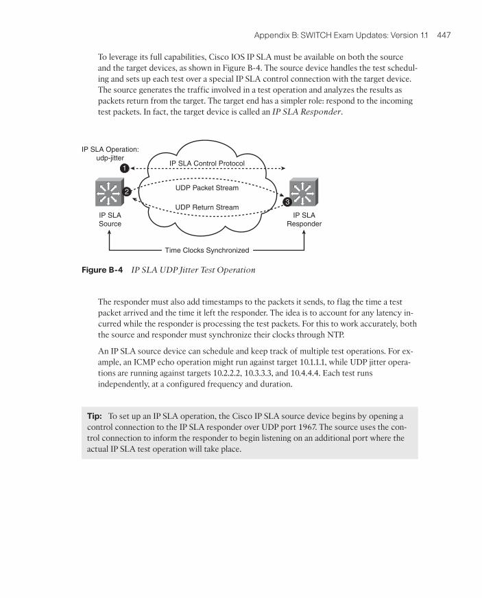
To leverage its full capabilities, Cisco IOS IP SLA must be available on both the sourceand the target devices, as shown in Figure B-4. The source device handles the test schedul-ing and sets up each test over a special IP SLA control connection with the target device.The source generates the traffic involved in a test operation and analyzes the results aspackets return from the target. The target end has a simpler role: respond to the incomingtest packets. In fact, the target device is called an IP SLA Responder.
The responder must also add timestamps to the packets it sends, to flag the time a testpacket arrived and the time it left the responder. The idea is to account for any latency in-curred while the responder is processing the test packets. For this to work accurately, boththe source and responder must synchronize their clocks through NTP.
An IP SLA source device can schedule and keep track of multiple test operations. For ex-ample, an ICMP echo operation might run against target 10.1.1.1, while UDP jitter opera-tions are running against targets 10.2.2.2, 10.3.3.3, and 10.4.4.4. Each test runsindependently, at a configured frequency and duration.
Tip: To set up an IP SLA operation, the Cisco IP SLA source device begins by opening acontrol connection to the IP SLA responder over UDP port 1967. The source uses the con-trol connection to inform the responder to begin listening on an additional port where theactual IP SLA test operation will take place.
IP SLA Control Protocol
IP SLAResponder
IP SLASource
IP SLA Operation:udp-jitter
UDP Return Stream
UDP Packet Stream2
1
3
Time Clocks Synchronized
Figure B-4 IP SLA UDP Jitter Test Operation
28_9781587202438_appb.qxp 9/1/10 11:49 AM Page 447
448 CCNP SWITCH 642-813 Official Certification Guide
What in the world does this have to do with LAN switching, and why would you want torun IP SLA on a Catalyst switch anyway? Here’s a two-fold answer:
■ IP SLA will likely appear on your SWITCH exam
■ IP SLA is actually a useful tool in a switched campus network
To run live tests and take useful measurements without IP SLA, you would need to placesome sort of probe devices at various locations in the network—all managed from a cen-tral system. With IP SLA, you don’t need probes at all! Wherever you have a Catalystswitch, you already have an IP SLA “probe.”
By leveraging IP SLA test operations, you can take advantage of some fancy features:
■ Generate SNMP traps when certain test thresholds are exceeded
■ Schedule further IP SLA tests automatically when test thresholds are crossed
■ Track an IP SLA test to trigger a next-hop gateway redundancy protocol, such as HSRP
■ Gather voice quality measurements from all over a network
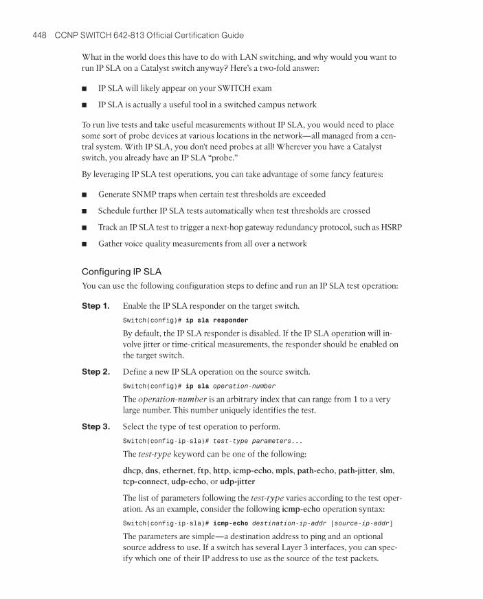
Configuring IP SLA
You can use the following configuration steps to define and run an IP SLA test operation:
Step 1. Enable the IP SLA responder on the target switch.
Switch(config)# ip sla responder
By default, the IP SLA responder is disabled. If the IP SLA operation will in-volve jitter or time-critical measurements, the responder should be enabled onthe target switch.
Step 2. Define a new IP SLA operation on the source switch.
Switch(config)# ip sla operation-number
The operation-number is an arbitrary index that can range from 1 to a verylarge number. This number uniquely identifies the test.
Step 3. Select the type of test operation to perform.
Switch(config-ip-sla)# test-type parameters...
The test-type keyword can be one of the following:
dhcp, dns, ethernet, ftp, http, icmp-echo, mpls, path-echo, path-jitter, slm,tcp-connect, udp-echo, or udp-jitter
The list of parameters following the test-type varies according to the test oper-ation. As an example, consider the following icmp-echo operation syntax:
Switch(config-ip-sla)# icmp-echo destination-ip-addr [source-ip-addr]
The parameters are simple—a destination address to ping and an optionalsource address to use. If a switch has several Layer 3 interfaces, you can spec-ify which one of their IP address to use as the source of the test packets.
28_9781587202438_appb.qxp 9/1/10 11:49 AM Page 448
Appendix B: SWITCH Exam Updates: Version 1.1 449
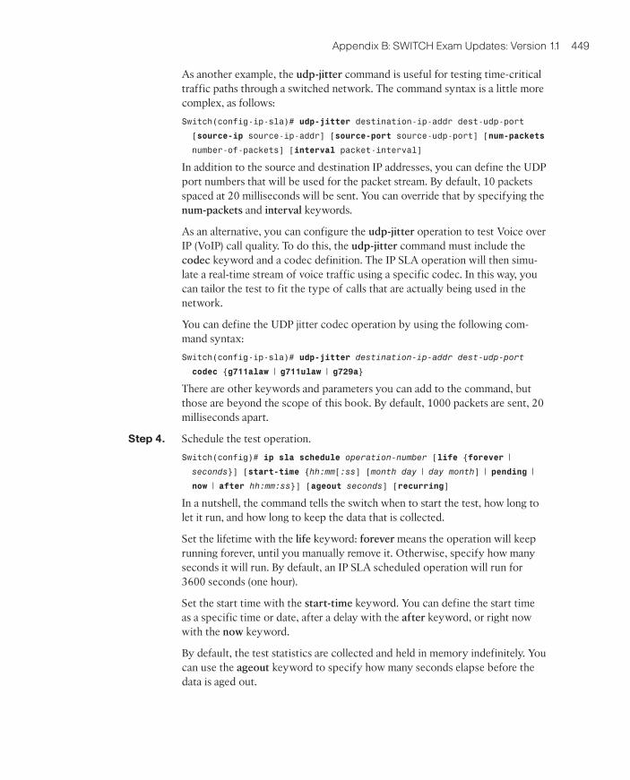
As another example, the udp-jitter command is useful for testing time-criticaltraffic paths through a switched network. The command syntax is a little morecomplex, as follows:
Switch(config-ip-sla)# udp-jitter destination-ip-addr dest-udp-port
[source-ip source-ip-addr] [source-port source-udp-port] [num-packets
number-of-packets] [interval packet-interval]
In addition to the source and destination IP addresses, you can define the UDPport numbers that will be used for the packet stream. By default, 10 packetsspaced at 20 milliseconds will be sent. You can override that by specifying thenum-packets and interval keywords.
As an alternative, you can configure the udp-jitter operation to test Voice overIP (VoIP) call quality. To do this, the udp-jitter command must include thecodec keyword and a codec definition. The IP SLA operation will then simu-late a real-time stream of voice traffic using a specific codec. In this way, youcan tailor the test to fit the type of calls that are actually being used in thenetwork.
You can define the UDP jitter codec operation by using the following com-mand syntax:
Switch(config-ip-sla)# udp-jitter destination-ip-addr dest-udp-port
codec {g711alaw | g711ulaw | g729a}
There are other keywords and parameters you can add to the command, butthose are beyond the scope of this book. By default, 1000 packets are sent, 20milliseconds apart.
Step 4. Schedule the test operation.
Switch(config)# ip sla schedule operation-number [life {forever |
seconds}] [start-time {hh:mm[:ss] [month day | day month] | pending |
now | after hh:mm:ss}] [ageout seconds] [recurring]
In a nutshell, the command tells the switch when to start the test, how long tolet it run, and how long to keep the data that is collected.
Set the lifetime with the life keyword: forever means the operation will keeprunning forever, until you manually remove it. Otherwise, specify how manyseconds it will run. By default, an IP SLA scheduled operation will run for3600 seconds (one hour).
Set the start time with the start-time keyword. You can define the start timeas a specific time or date, after a delay with the after keyword, or right nowwith the now keyword.
By default, the test statistics are collected and held in memory indefinitely. Youcan use the ageout keyword to specify how many seconds elapse before thedata is aged out.
28_9781587202438_appb.qxp 9/1/10 11:49 AM Page 449
450 CCNP SWITCH 642-813 Official Certification Guide
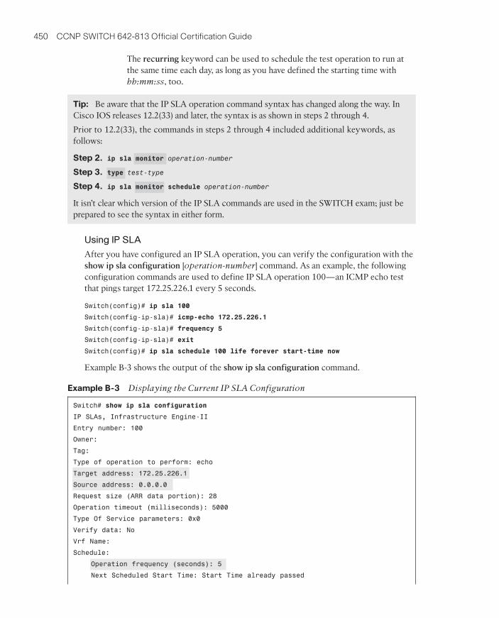
The recurring keyword can be used to schedule the test operation to run atthe same time each day, as long as you have defined the starting time withhh:mm:ss, too.
Using IP SLA
After you have configured an IP SLA operation, you can verify the configuration with theshow ip sla configuration [operation-number] command. As an example, the followingconfiguration commands are used to define IP SLA operation 100—an ICMP echo testthat pings target 172.25.226.1 every 5 seconds.
Switch(config)# ip sla 100
Switch(config-ip-sla)# icmp-echo 172.25.226.1
Switch(config-ip-sla)# frequency 5
Switch(config-ip-sla)# exit
Switch(config)# ip sla schedule 100 life forever start-time now
Example B-3 shows the output of the show ip sla configuration command.
Example B-3 Displaying the Current IP SLA Configuration
Switch# show ip sla configuration
IP SLAs, Infrastructure Engine-II
Entry number: 100
Owner:
Tag:
Type of operation to perform: echo
Target address: 172.25.226.1
Source address: 0.0.0.0
Request size (ARR data portion): 28
Operation timeout (milliseconds): 5000
Type Of Service parameters: 0x0
Verify data: No
Vrf Name:
Schedule:
Operation frequency (seconds): 5
Next Scheduled Start Time: Start Time already passed
Tip: Be aware that the IP SLA operation command syntax has changed along the way. InCisco IOS releases 12.2(33) and later, the syntax is as shown in steps 2 through 4.
Prior to 12.2(33), the commands in steps 2 through 4 included additional keywords, asfollows:
Step 2. ip sla monitor operation-number
Step 3. type test-type
Step 4. ip sla monitor schedule operation-number
It isn’t clear which version of the IP SLA commands are used in the SWITCH exam; just beprepared to see the syntax in either form.
28_9781587202438_appb.qxp 9/1/10 11:49 AM Page 450
Appendix B: SWITCH Exam Updates: Version 1.1 451
Group Scheduled : FALSE
Randomly Scheduled : FALSE
Life (seconds): Forever
Entry Ageout (seconds): never
Recurring (Starting Everyday): FALSE
Status of entry (SNMP RowStatus): Active
Threshold (milliseconds): 5000
Distribution Statistics:
Number of statistic hours kept: 2
Number of statistic distribution buckets kept: 1
Statistic distribution interval (milliseconds): 20
History Statistics:
Number of history Lives kept: 0
Number of history Buckets kept: 15
History Filter Type: None
Enhanced History:
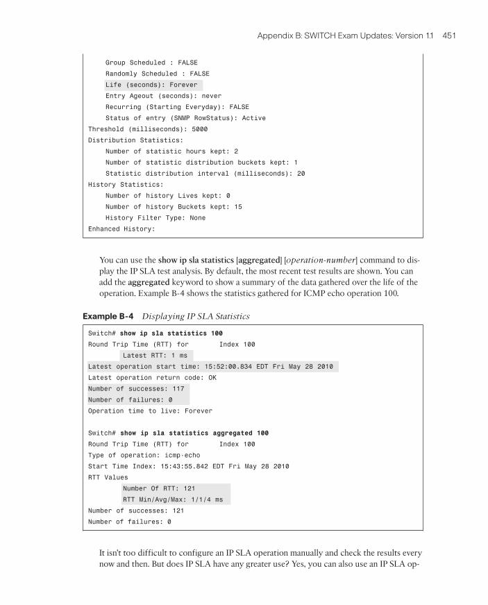
You can use the show ip sla statistics [aggregated] [operation-number] command to dis-play the IP SLA test analysis. By default, the most recent test results are shown. You canadd the aggregated keyword to show a summary of the data gathered over the life of theoperation. Example B-4 shows the statistics gathered for ICMP echo operation 100.
Example B-4 Displaying IP SLA Statistics
Switch# show ip sla statistics 100
Round Trip Time (RTT) for Index 100
Latest RTT: 1 ms
Latest operation start time: 15:52:00.834 EDT Fri May 28 2010
Latest operation return code: OK
Number of successes: 117
Number of failures: 0
Operation time to live: Forever
Switch# show ip sla statistics aggregated 100
Round Trip Time (RTT) for Index 100
Type of operation: icmp-echo
Start Time Index: 15:43:55.842 EDT Fri May 28 2010
RTT Values
Number Of RTT: 121
RTT Min/Avg/Max: 1/1/4 ms
Number of successes: 121
Number of failures: 0
It isn’t too difficult to configure an IP SLA operation manually and check the results everynow and then. But does IP SLA have any greater use? Yes, you can also use an IP SLA op-
28_9781587202438_appb.qxp 9/1/10 11:49 AM Page 451

452 CCNP SWITCH 642-813 Official Certification Guide
eration to make some other switch features change behavior automatically, without anyother intervention.
For example, HSRP can track the status of an IP SLA operation to automatically decre-ment the priority value when the target device stops answering ICMP echo packets. To dothis, begin by using the track command to define a unique track object-number indexthat will be bound to the IP SLA operation number.
Switch(config)# track object-number ip sla operation-number {state | reachability}
You can use the state keyword to track the return code or state of the IP SLA operation;the state is up if the IP SLA test was successful or down if it wasn’t. The reachability key-word is slightly different—the result is up if the IP SLA operation is successful or hasrisen above a threshold; otherwise, the reachability is down.
Next, configure the HSRP standby group to use the tracked object to control the prioritydecrement value. As long as the tracked object (the IP SLA operation) is up or successful,the HSRP priority stays unchanged. If the tracked object is down, then the HSRP priorityis decremented by decrement-value (default 10).
Switch(config-if)# standby group track object-number decrement decrement-value
In Example B-5, SwitchA and SwitchB are configured as an HSRP pair, sharing gatewayaddress 192.168.1.1. SwitchA has a higher priority than SwitchB, so it is normally the ac-tive gateway. However, it is configured to ping an upstream router at 192.168.70.1 everyfive seconds; if that router doesn’t respond, SwitchA will decrement its HSRP priority by50, permitting SwitchB to take over.
Example B-5 Tracking an IP SLA Operation in an HSRP Group
Switch(config)# ip sla 10
Switch(config-ip-sla)# icmp-echo 192.168.70.1
Switch(config-ip-sla)# frequency 5
Switch(config-ip-sla)# exit
Switch(config)# ip sla schedule 10 life forever start-time now
Switch(config)# track 1 ip sla 10 reachability
Switch(config)# interface vlan10
Switch(config-if)# ip address 192.168.1.3 255.255.255.0
Switch(config-if)# standby 1 priority 200
Switch(config-if)# standby 1 track 1 decrement 50
Switch(config-if)# no shutdown
28_9781587202438_appb.qxp 9/1/10 11:49 AM Page 452
Appendix B: SWITCH Exam Updates: Version 1.1 453
In some cases, you might need many IP SLA operations to take many measurements in anetwork. For example, you could use UDP jitter operations to measure voice call qualityacross many different parts of the network. Manually configuring and monitoring morethan a few IP SLA operations can become overwhelming and impractical. Instead, you canleverage a network management application that can set up and monitor IP SLA tests auto-matically. To do this, the network management system needs SNMP read and write accessto each switch that will use IP SLA. Tests are configured by writing to the IP SLA MIB,and results are gathered by reading the MIB.
28_9781587202438_appb.qxp 9/1/10 11:49 AM Page 453