28 feb 2000isat 3001 resistance temperature detectors (rtds)
TRANSCRIPT
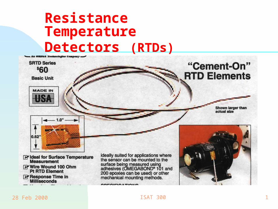
28 Feb 2000 ISAT 300 1
Resistance Temperature Detectors (RTDs)
28 Feb 2000 ISAT 300 2
Bridge CircuitsISAT 300
Spring 1999

28 Feb 2000 ISAT 300 3
Wheatstone Bridge
A circuit designed to measure changes in resistance
In Instrumentation it is used as signal conditioning for strain gages

28 Feb 2000 ISAT 300 4
Vs
R1 R2
R3R4
+
-
- +Vo
A
B
C
D

28 Feb 2000 ISAT 300 5
Build a Wheatstone Bridge
Vs
+
-
R2
R3
V2
V3
32
33
32
22
RR
RVV
RR
RVV
s
s

28 Feb 2000 ISAT 300 6
Build A Wheatstone Bridge
Vs
+
-
R2
R3
V2
V3
R1
R4
V1
V4
Vo
41
1
32
2
12
RR
RV
RR
RVV
VVV
sso
o
Or
41
4
32
3
RR
RV
RR
RVV sso
430 VVV
Apply Kirchoff’s Voltage Law:

28 Feb 2000 ISAT 300 7
Balancing the Bridge
41
4
32
3
RR
RV
RR
RVV sso
Governing Equation
Multiply by a common denominator
4132
2413
RRRR
RRRRVV so
3241
324
4132
413
RRRR
RRRV
RRRR
RRRVV sso
Simplify

28 Feb 2000 ISAT 300 8
Balance The Bridge
The bridge is balanced if the output is zero
0.00 V
0
if 0
2413
4132
2413
RRRR
RRRR
RRRRVV so
28 Feb 2000 ISAT 300 9
]2
2[
][
2
221
21
2
41
4
2
41
4
32
3
os
osRTD
RTD
RTD
s
o
RTD
RTDso
sRTD
RTDso
sso
VV
VVRR
RR
R
V
V
RR
RVV
RR
RV
RR
RVV
RR
RV
RR
RVV
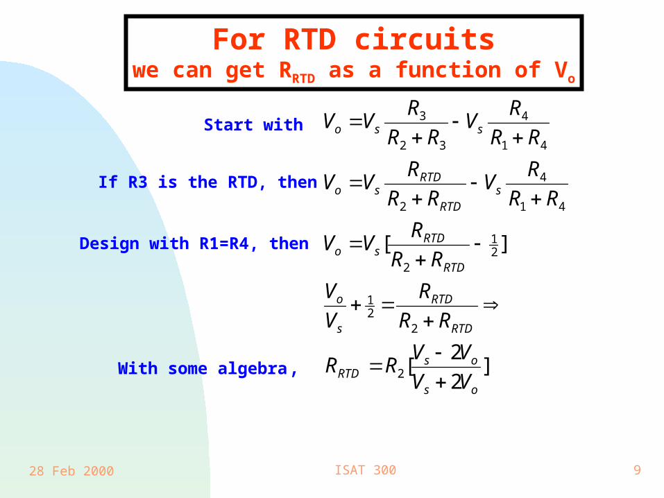
If R3 is the RTD, then
With some algebra,
For RTD circuitswe can get RRTD as a function of Vo
Start with
Design with R1=R4, then
28 Feb 2000 ISAT 300 10
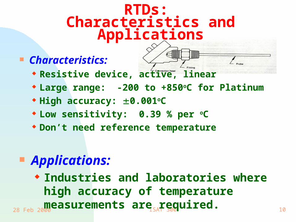
RTDs: Characteristics and Applications
Characteristics: Resistive device, active, linear Large range: -200 to +850oC for Platinum High accuracy: 0.001oC Low sensitivity: 0.39 % per oC Don’t need reference temperature
Applications: Industries and laboratories where high
accuracy of temperature measurements are required.

28 Feb 2000 ISAT 300 11
Thin-Film RTDs
Thin-film RTD design is a newer technology and is gaining favor due to lower cost. It is designed to minimize strain on the platinum due to thermal expansion since strain also cause changes in resistance, R =(L/A).

28 Feb 2000 ISAT 300 12
Calendar-Van Dusen Equation
For platinum, the resistance temperature relationship is given by the Calendar-Van Dusen equation:
R R T T T T TT o { [ ( . )( . ) ( . )( . ) ]}1 0 0 1 1 0 0 1 0 0 1 1 0 0 1 3
w h ere an d a re co n s tan ts , d ep en d en t o n
th e p u rity o f p la tin u m . , an d fo r
an d fo r .
, ,
1 4 9 0 0
0 11 0
. = T >
= . T <
For the U. S. calibration curve, = 0.003851/°C
(U.S. calibration curve, text p 248)

28 Feb 2000 ISAT 300 13
Platinum RTD: R versus T (U.S. Calibration)
0
50
100
150
200
250
300
-100 0 100 200 300 400
Temperature (C)
Re
sis
tan
ce (
Oh
m)
Equation (9.10)
Table 9.3
28 Feb 2000 ISAT 300 14
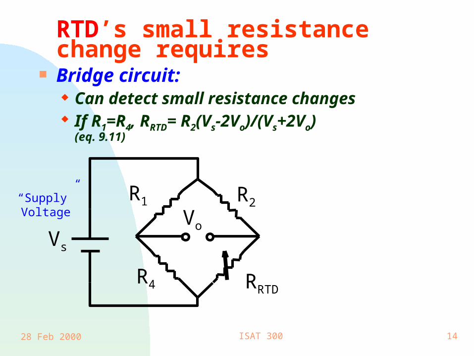
RTD’s small resistance change requires
Bridge circuit: Can detect small resistance changes If R1=R4, RRTD= R2(Vs-2Vo)/(Vs+2Vo)
(eq. 9.11)
R1 R2
RRTDR4
VoVs
“Supply”Voltage
28 Feb 2000 ISAT 300 15
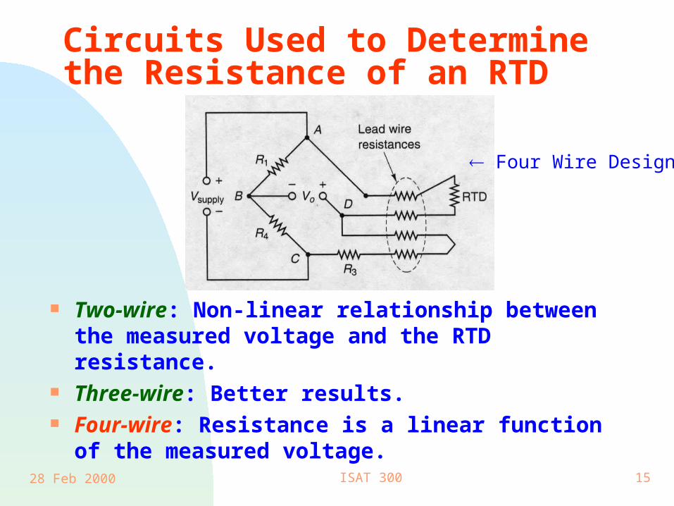
Circuits Used to Determine the Resistance of an RTD
Two-wire: Non-linear relationship between the measured voltage and the RTD resistance.
Three-wire: Better results. Four-wire: Resistance is a linear function of the
measured voltage.
Four Wire Design

28 Feb 2000 ISAT 300 16
Example: An RTD probe has a resistance of 100 at 0oC. The Calendar-Van Dusen constants are = 0.00392, = 1.49, and = 0 for T > 0oC. What will be the resistance at 350oC.
R T
1 0 0 1 0 0 0 3 9 2 3 5 0 1 4 9 0 0 1 3 5 0 1 0 0 1 3 5 0
0 0 0 0 1 3 5 0 1 0 0 1 3 5 0
2 3 2 0 8
3
{ . [ . ( . )( . )
. ( . )( . ) ]}
. .
Alternatively, we could use table 9.3 (p248) and obtain RT = 231.89 .
(RT=RRTD)

28 Feb 2000 ISAT 300 17
Summary Thermocouples
Passive, non-linear, increase temperature increase voltages, big temperature range.
Types K and T are common devices. Need reference temperature
Thermistors Active, highly non-linear, increase temperature
decrease resistance. Medical use, not available above 300oC.
RTD’s Requires a Bridge, Linear by nature. High accuracy, use in industry & laboratory.
ALL: time constant of a first order system