2.810 manufacturing processes and...
TRANSCRIPT
1
2.810 manufacturing processes
and systems
Prof. Tim Gutowski, [email protected]
September 5, 2018
Prereq: 2.001, 2.006, 2.008
(translation: solid & fluid mech, heat transfer, mfg)
2
Today’s Agenda
• Business
– Administrative stuff
– Your background
• Concepts
– Manufacturing Enterprise – Big Picture
– Processes
– Systems
3
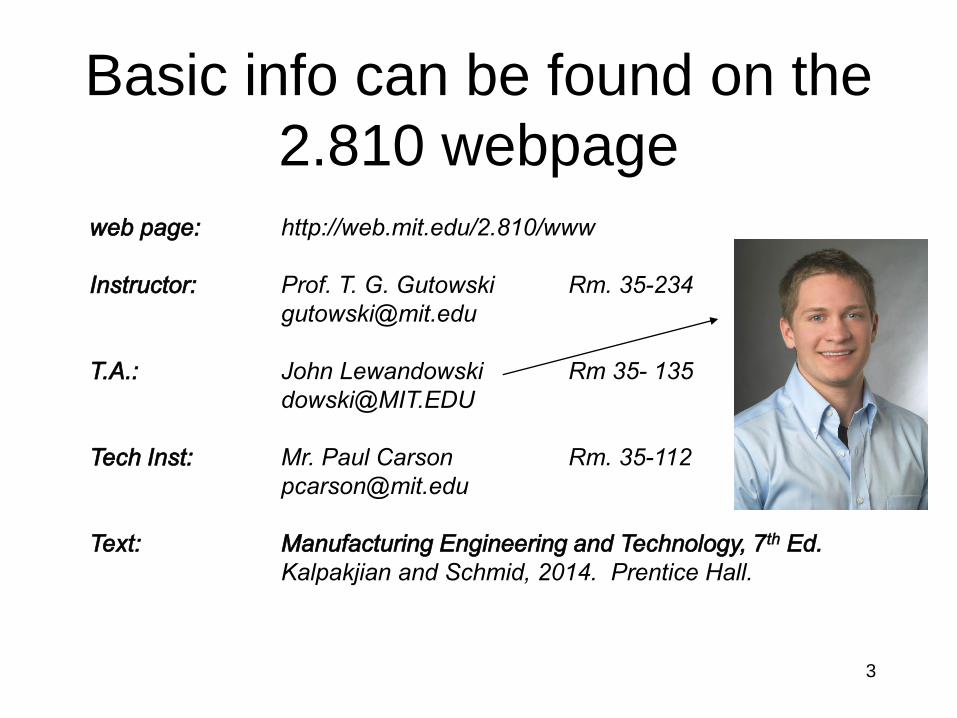
Basic info can be found on the
2.810 webpage
web page: http://web.mit.edu/2.810/www
Instructor: Prof. T. G. Gutowski Rm. 35-234
T.A.: John Lewandowski Rm 35- 135
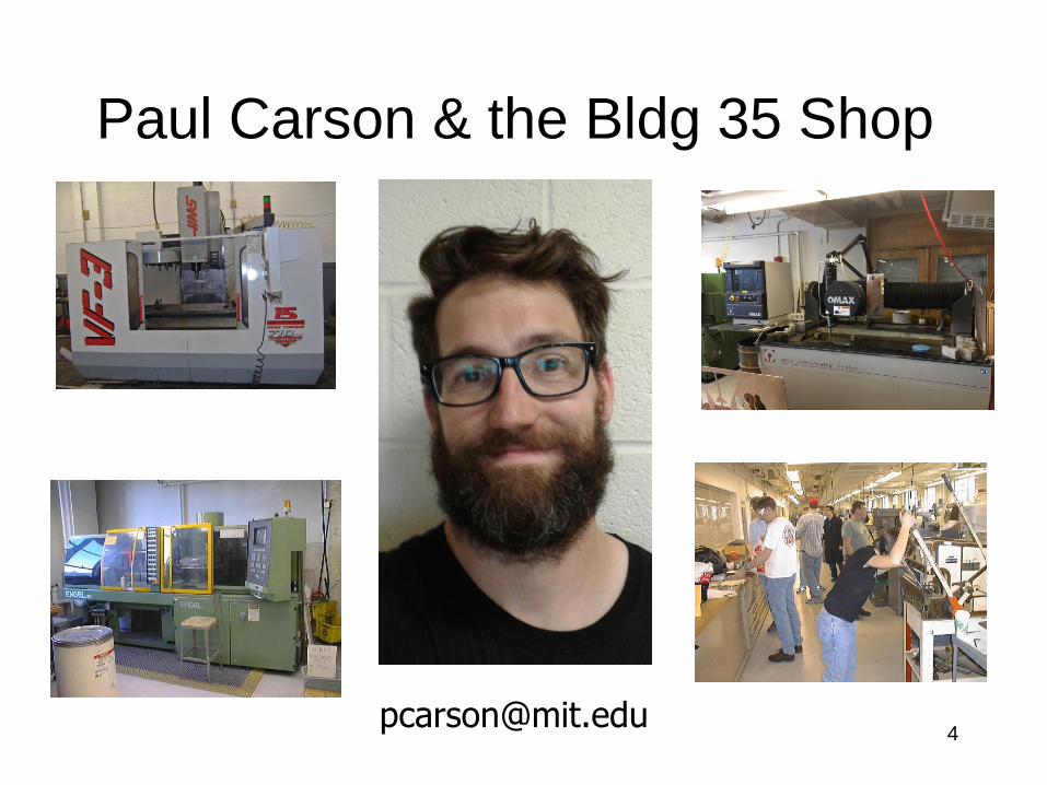
Tech Inst: Mr. Paul Carson Rm. 35-112
Text: Manufacturing Engineering and Technology, 7th Ed.
Kalpakjian and Schmid, 2014. Prentice Hall.
5
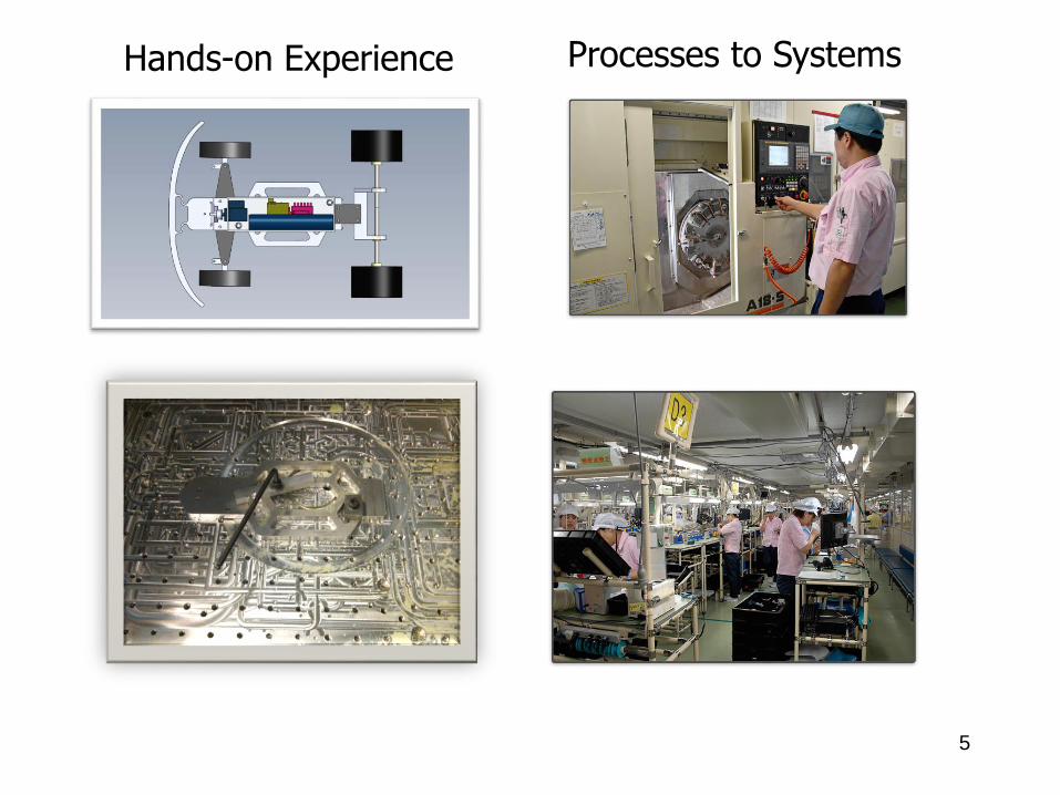
Hands-on Experience Processes to Systems
6
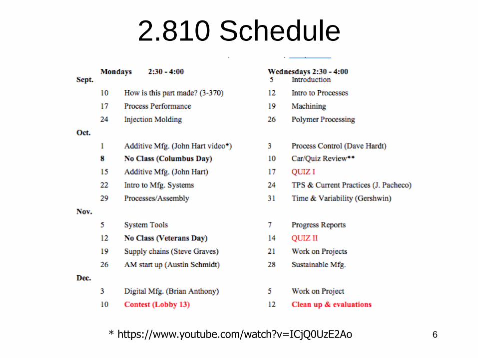
2.810 Schedule
* https://www.youtube.com/watch?v=ICjQ0UzE2Ao
7
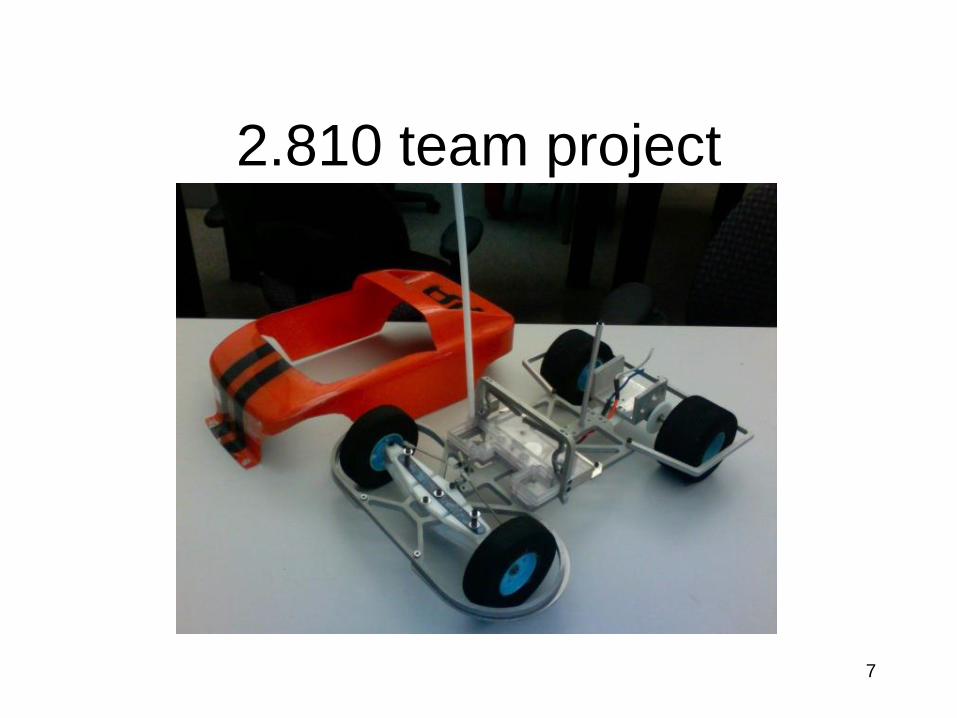
2.810 team project
8
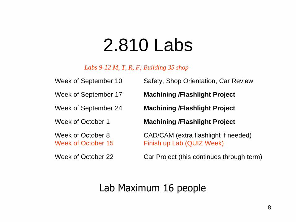
2.810 LabsLabs 9-12 M, T, R, F; Building 35 shop
Week of September 10 Safety, Shop Orientation, Car Review
Week of September 17 Machining /Flashlight Project
Week of September 24 Machining /Flashlight Project
Week of October 1 Machining /Flashlight Project
Week of October 8 CAD/CAM (extra flashlight if needed)
Week of October 15 Finish up Lab (QUIZ Week)
Week of October 22 Car Project (this continues through term)
Lab Maximum 16 people
9
Teams and Labs are Different
• Labs occur at the beginning of the term:
basic skills some CNC
• Teams are to build cars: you select your
team members, usually 4 to 6 per team
10
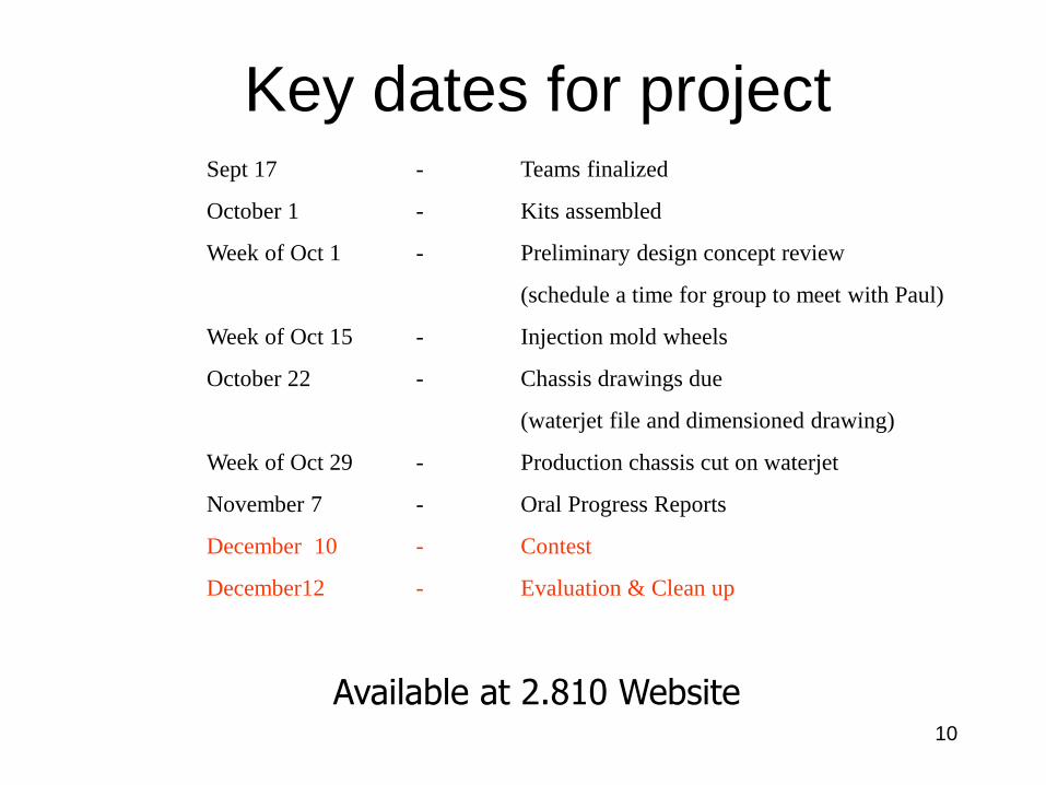
Key dates for project
Available at 2.810 Website
Sept 17 - Teams finalized
October 1 - Kits assembled
Week of Oct 1 - Preliminary design concept review
(schedule a time for group to meet with Paul)
Week of Oct 15 - Injection mold wheels
October 22 - Chassis drawings due
(waterjet file and dimensioned drawing)
Week of Oct 29 - Production chassis cut on waterjet
November 7 - Oral Progress Reports
December 10 - Contest
December12 - Evaluation & Clean up
11
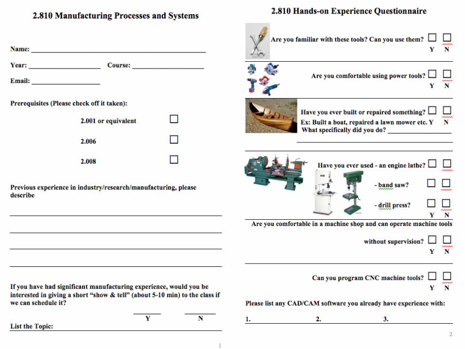
Please fill out information form;
background, interests, skills
•Basic information
•Experience in shop
•Experience in mfg
12

13
Lab Sign-up
• See Google Doc: web & email
• State your availability & preference
• See schedule (don’t miss first 5 weeks)
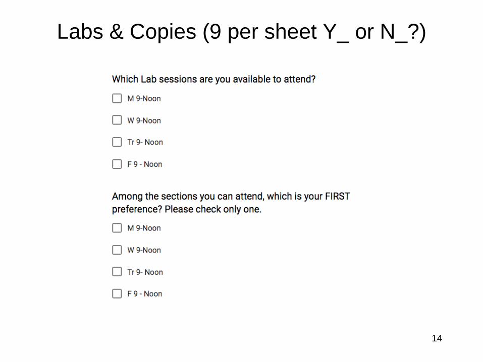
Labs & Copies (9 per sheet Y_ or N_?)
14
15
16
The Mfg Enterprise – Big Picture
• Industrialization and Economic Growth
• Big Push Industrialization
• Divergence
• Democracy and Political Development
• The Future: Growth? Employment?
Environment?
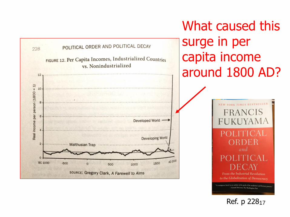
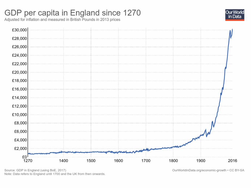
What caused this surge in percapita income around 1800 AD?
Ref. p 22817
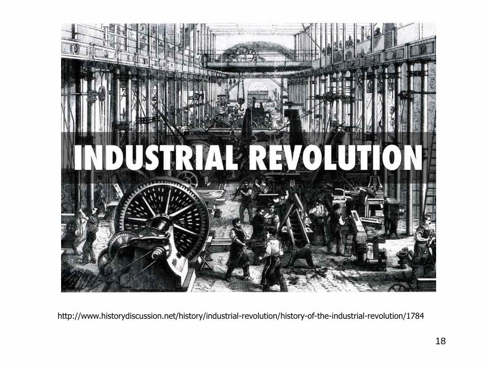
18
http://www.historydiscussion.net/history/industrial-revolution/history-of-the-industrial-revolution/1784
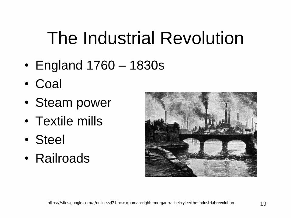
The Industrial Revolution
• England 1760 – 1830s
• Coal
• Steam power
• Textile mills
• Steel
• Railroads
19https://sites.google.com/a/online.sd71.bc.ca/human-rights-morgan-rachel-rylee/the-industrial-revolution
20
21
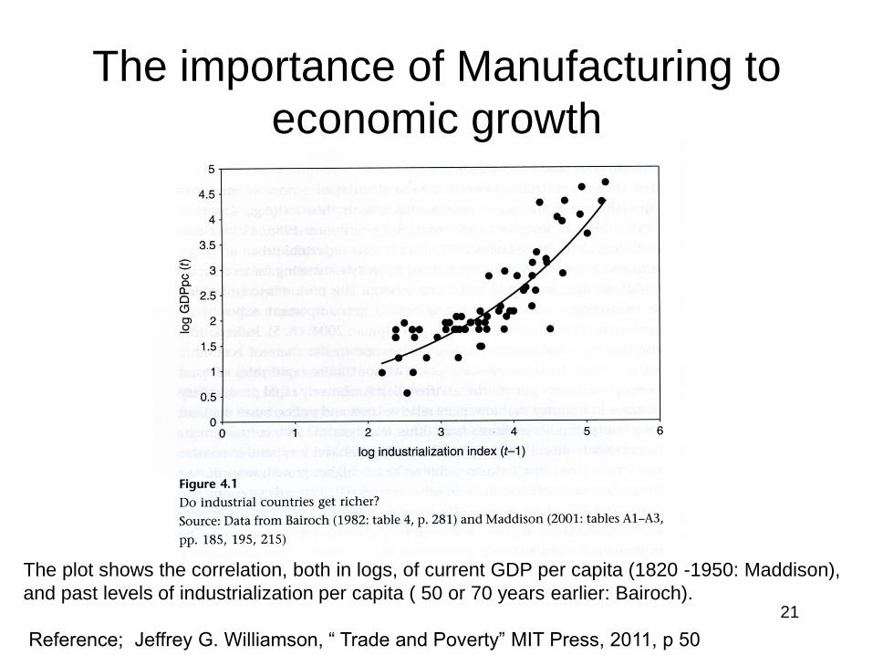
The plot shows the correlation, both in logs, of current GDP per capita (1820 -1950: Maddison),
and past levels of industrialization per capita ( 50 or 70 years earlier: Bairoch).
Reference; Jeffrey G. Williamson, “ Trade and Poverty” MIT Press, 2011, p 50
The importance of Manufacturing to
economic growth
22
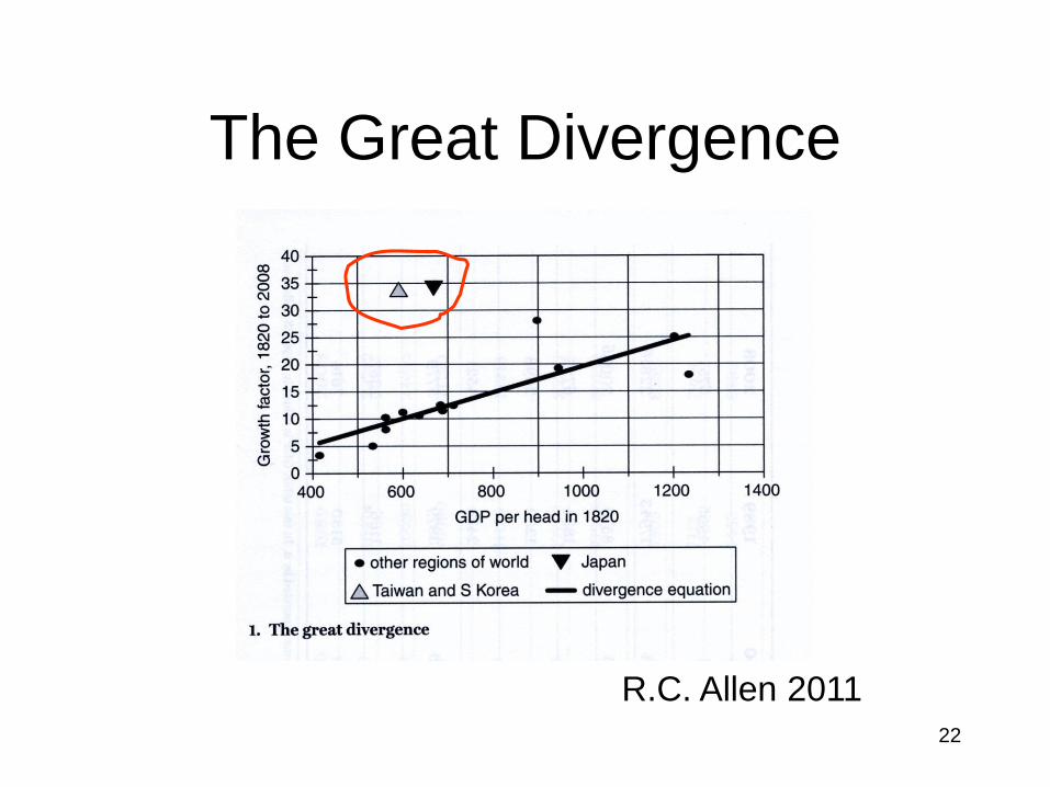
The Great Divergence
R.C. Allen 2011
23
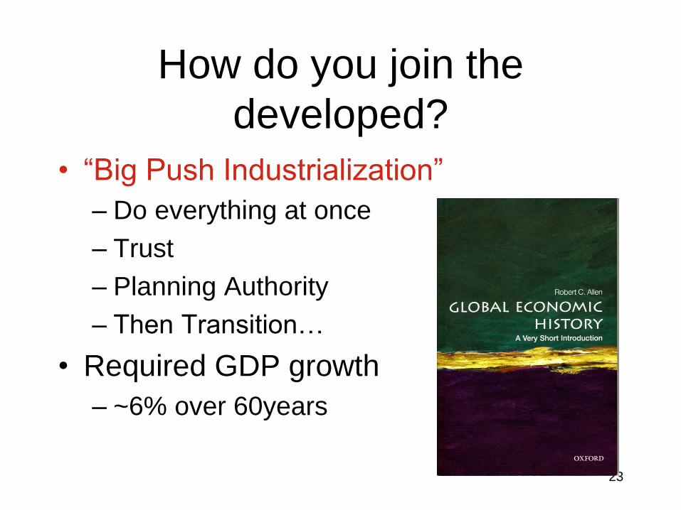
How do you join the
developed?
• “Big Push Industrialization”
– Do everything at once
– Trust
– Planning Authority
– Then Transition…
• Required GDP growth
– ~6% over 60years

24
How do you join the
developed?• “Big Push Industrialization”
– Japan
– South Korea
– Taiwan
• Less successful
– Russia
– South America
25
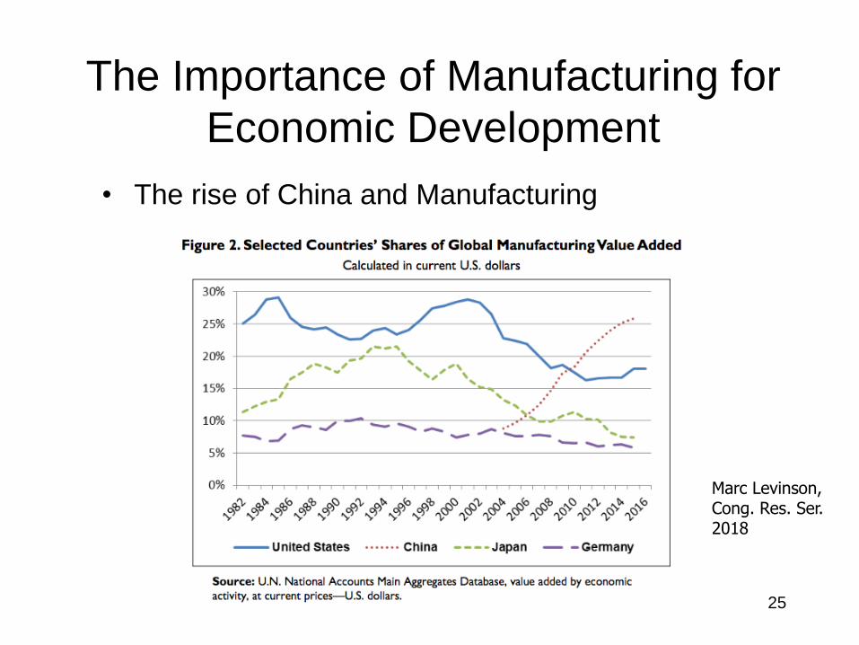
The Importance of Manufacturing for
Economic Development
• The rise of China and Manufacturing
Marc Levinson,Cong. Res. Ser.2018
26
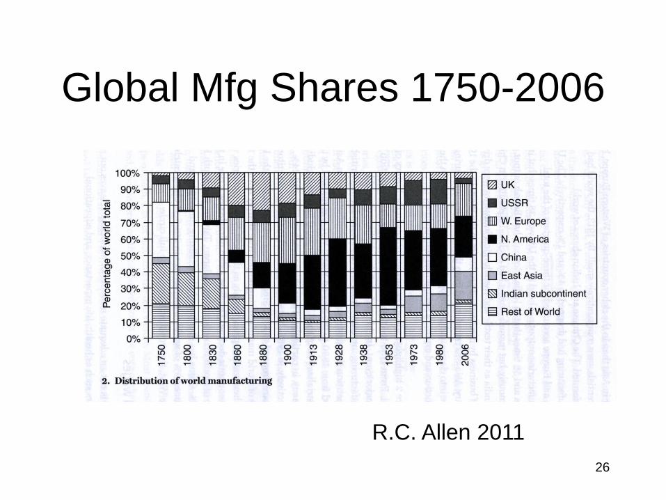
Global Mfg Shares 1750-2006
R.C. Allen 2011
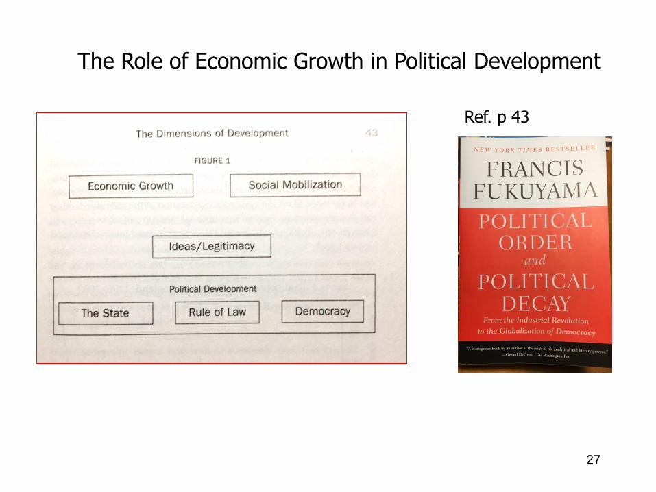
Ref. p 43
The Role of Economic Growth in Political Development
27
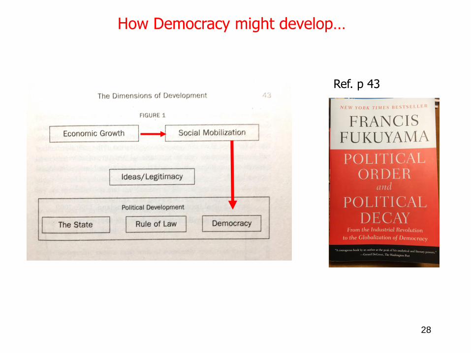
Ref. p 43
How Democracy might develop…
28
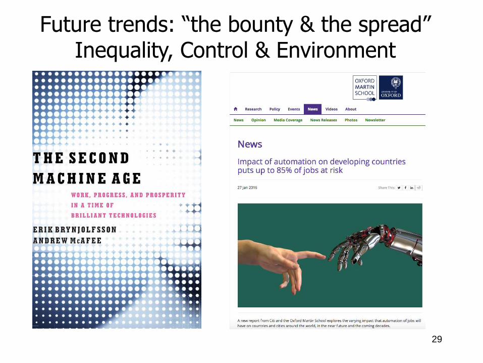
29
Future trends: “the bounty & the spread”Inequality, Control & Environment
30
31
Basic Concepts for 2.810
1. Manufacturing
Processes
– Abstraction
– Performance
Attributes
– Classification
Schemes
2. Manufacturing
Systems
– Physical part
– Required machines
– Process steps
– Equipment
arrangements
32
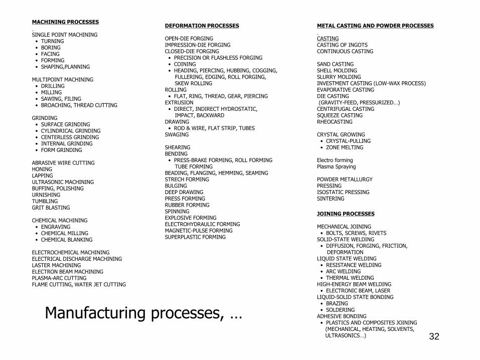
MACHINING PROCESSES
SINGLE POINT MACHINING• TURNING• BORING• FACING• FORMING• SHAPING,PLANNING
MULTIPOINT MACHINING• DRILLING• MILLING• SAWING, FILING• BROACHING, THREAD CUTTING
GRINDING• SURFACE GRINDING• CYLINDRICAL GRINDING• CENTERLESS GRINDING• INTERNAL GRINDING• FORM GRINDING
ABRASIVE WIRE CUTTINGHONINGLAPPINGULTRASONIC MACHININGBUFFING, POLISHINGURNISHINGTUMBLINGGRIT BLASTING
CHEMICAL MACHINING• ENGRAVING• CHEMICAL MILLING• CHEMICAL BLANKING
ELECTROCHEMICAL MACHININGELECTRICAL DISCHARGE MACHININGLASTER MACHININGELECTRON BEAM MACHININGPLASMA-ARC CUTTINGFLAME CUTTING, WATER JET CUTTING
DEFORMATION PROCESSES
OPEN-DIE FORGINGIMPRESSION-DIE FORGINGCLOSED-DIE FORGING
• PRECISION OR FLASHLESS FORGING• COINING• HEADING, PIERCING, HUBBING, COGGING,
FULLERING, EDGING, ROLL FORGING, SKEW ROLLING
ROLLING• FLAT, RING, THREAD, GEAR, PIERCING
EXTRUSION• DIRECT, INDIRECT HYDROSTATIC,
IMPACT, BACKWARDDRAWING
• ROD & WIRE, FLAT STRIP, TUBESSWAGING
SHEARINGBENDING
• PRESS-BRAKE FORMING, ROLL FORMINGTUBE FORMING
BEADING, FLANGING, HEMMING, SEAMINGSTRECH FORMINGBULGINGDEEP DRAWINGPRESS FORMINGRUBBER FORMINGSPINNINGEXPLOSIVE FORMINGELECTROHYDRAULIC FORMINGMAGNETIC-PULSE FORMINGSUPERPLASTIC FORMING
METAL CASTING AND POWDER PROCESSES
CASTINGCASTING OF INGOTSCONTINUOUS CASTING
SAND CASTINGSHELL MOLDINGSLURRY MOLDINGINVESTMENT CASTING (LOW-WAX PROCESS)EVAPORATIVE CASTINGDIE CASTING(GRAVITY-FEED, PRESSURIZED…)
CENTRIFUGAL CASTINGSQUEEZE CASTINGRHEOCASTING
CRYSTAL GROWING• CRYSTAL-PULLING• ZONE MELTING
Electro formingPlasma Spraying
POWDER METALLURGYPRESSINGISOSTATIC PRESSINGSINTERING
JOINING PROCESSES
MECHANICAL JOINING• BOLTS, SCREWS, RIVETS
SOLID-STATE WELDING• DIFFUSION, FORGING, FRICTION,
DEFORMATIONLIQUID STATE WELDING
• RESISTANCE WELDING• ARC WELDING• THERMAL WELDING
HIGH-ENERGY BEAM WELDING• ELECTRONIC BEAM, LASER
LIQUID-SOLID STATE BONDING• BRAZING• SOLDERING
ADHESIVE BONDING• PLASTICS AND COMPOSITES JOINING
(MECHANICAL, HEATING, SOLVENTS,ULTRASONICS…)
Manufacturing processes, …
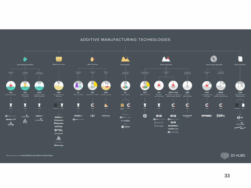
33
34
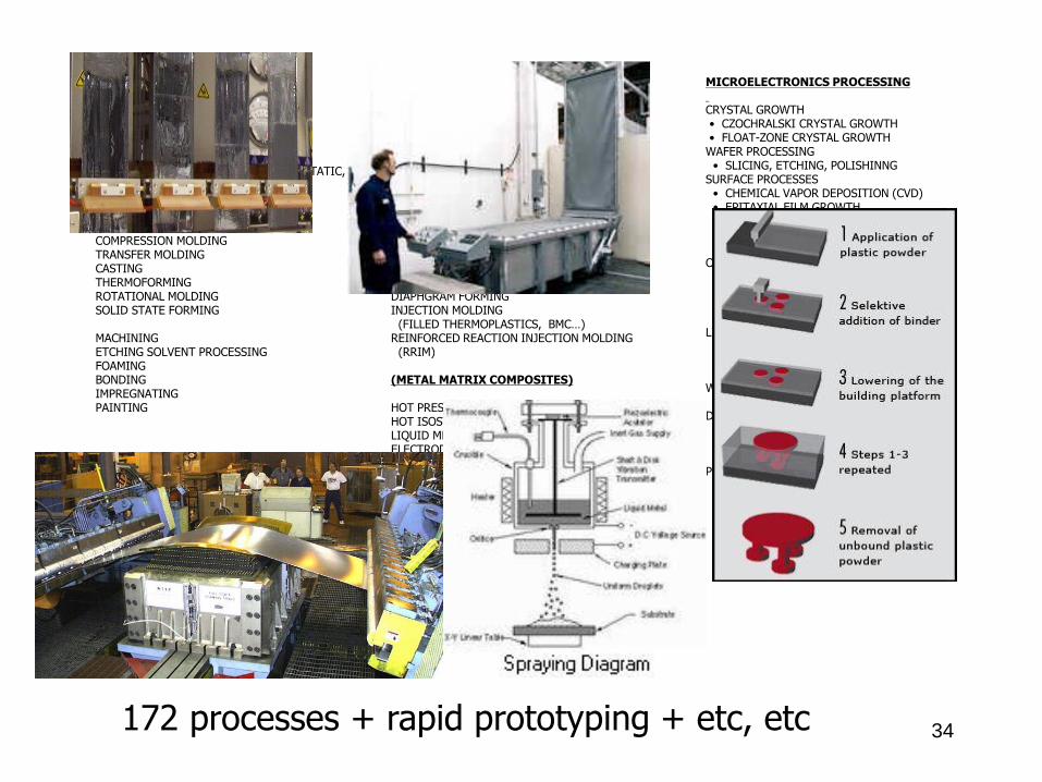
MICROELECTRONICS PROCESSING
CRYSTAL GROWTH• CZOCHRALSKI CRYSTAL GROWTH• FLOAT-ZONE CRYSTAL GROWTH
WAFER PROCESSING• SLICING, ETCHING, POLISHINNG
SURFACE PROCESSES• CHEMICAL VAPOR DEPOSITION (CVD)• EPITAXIAL FILM GROWTH• POLY CRYSTALLINE FILM GROWTH• S102 FILMS• OTHER (DIELECTRICS, METALS)
OXIDATION• ION IMPLANTATION• PHYSICAL VAPOR DEPOSITION• SPUTTERING• EVAPORATION
LITHOGRAPHY• PHOTORESIST• ELECTRON BEAM, X-RAY, ION BEAM
LITHOGRAPHYWET ETCHING
• CHEMICALDRY ETCHING• PLASMA• SPUTTER• REACTIVE ION
PACKAGING• DICING• DIE ATTACHMENT• WIRE BONDING• ENCAPSULATION
POLYMER PROCESSES
EXTRUSIONFIBER SPINNINGCALANDERINGFILM BLOWINGCOATING(MELTS, SOLUTION, PLASMA, ELECTROSTATIC,PLASTISOL, UV CURABLE…)
BLOW MOLDINGINJECTION MOLDINGREACTION INJECTION MOLDING (RIM)COMPRESSION MOLDINGTRANSFER MOLDINGCASTINGTHERMOFORMINGROTATIONAL MOLDINGSOLID STATE FORMING
MACHININGETCHING SOLVENT PROCESSINGFOAMINGBONDINGIMPREGNATINGPAINTING
COMPOSITES PROCESSES
(POLYMER COMPOSITES)
PULTRUSIONFILAMENT WINDINGPULL FORMINGBRAIDINGAUTOCLAVE MOLDINGCOMPRESSION MOLDING (SMC)RESIN TRANSFER MOLDINGAUTOCOMP MOLDINGHAND LAY-UPSPRAY-UPAUTOMATIC TAPE LAY-UPSTAMPINGDIAPHGRAM FORMINGINJECTION MOLDING
(FILLED THERMOPLASTICS, BMC…)REINFORCED REACTION INJECTION MOLDING
(RRIM)
(METAL MATRIX COMPOSITES)
HOT PRESSURE BONDINGHOT ISOSTATIC PRESSINGLIQUID METAL INFILTRATIONELECTRODEPOSITIONPLASMA SPRAY DEPOSITION
CERAMICS PROCESSES
POWER PROCESSES• CONSOLIDATION• SINTERING
MELT PROCESSES• CRYSTALLINE MATERIALS (SILICON)• GLASSES• DRAWING, CASTING, BLOWING, TEMPERING
(OPTICAL & STRUCTURAL FILTERS)• COATING
SOL-GEL CERAMICS PROCESSING
172 processes + rapid prototyping + etc, etc
35
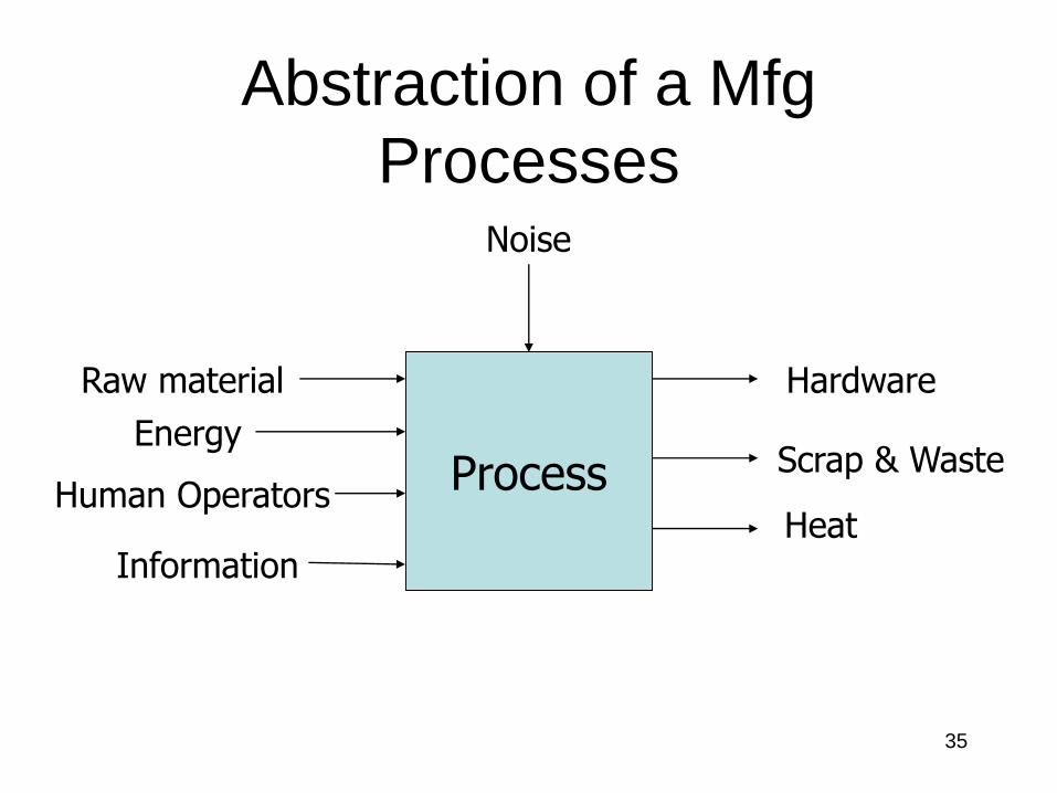
Abstraction of a Mfg
Processes
Process
Hardware
Scrap & Waste
Raw material
Energy
Noise
Information
Human OperatorsHeat
36
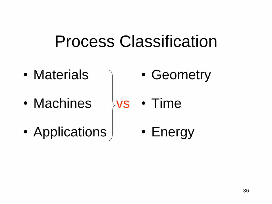
Process Classification
• Materials
• Machines vs
• Applications
• Geometry
• Time
• Energy
37
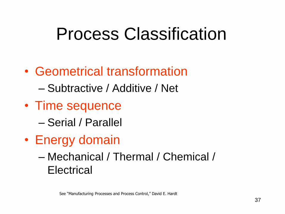
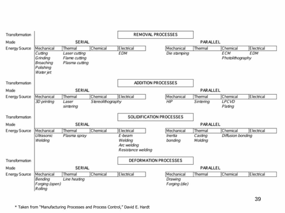
Process Classification
• Geometrical transformation
– Subtractive / Additive / Net
• Time sequence
– Serial / Parallel
• Energy domain
– Mechanical / Thermal / Chemical /
Electrical
See “Manufacturing Processes and Process Control,” David E. Hardt
38
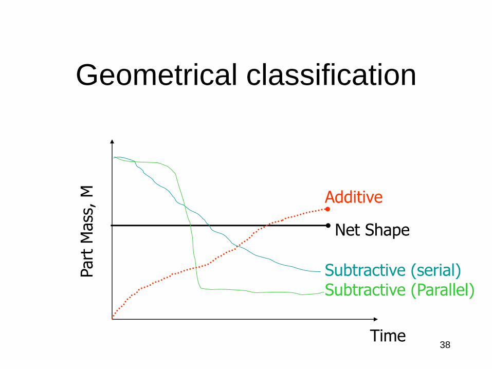
Geometrical classification
Time
Part
Mass
, M
Subtractive (serial)Subtractive (Parallel)
Net Shape
Additive
39
* Taken from “Manufacturing Processes and Process Control,” David E. Hardt
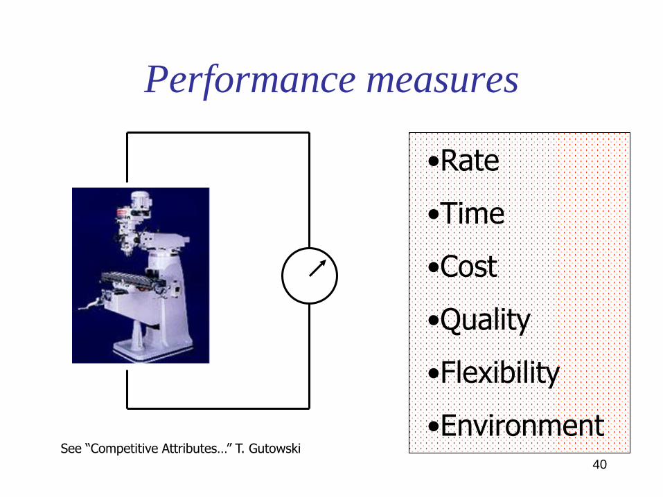
40
Performance measures
•Rate
•Time
•Cost
•Quality
•Flexibility
•EnvironmentSee “Competitive Attributes…” T. Gutowski
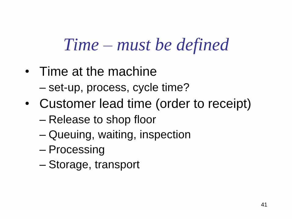
41
Time – must be defined
• Time at the machine
– set-up, process, cycle time?
• Customer lead time (order to receipt)
– Release to shop floor
– Queuing, waiting, inspection
– Processing
– Storage, transport
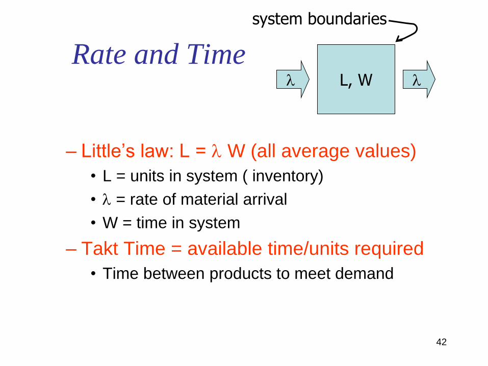
42
Rate and Time
– Little’s law: L = W (all average values)
• L = units in system ( inventory)
• = rate of material arrival
• W = time in system
– Takt Time = available time/units required
• Time between products to meet demand
L, W
system boundaries
43
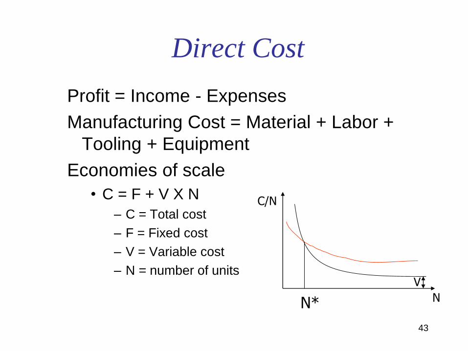
Direct Cost
Profit = Income - Expenses
Manufacturing Cost = Material + Labor +
Tooling + Equipment
Economies of scale
• C = F + V X N
– C = Total cost
– F = Fixed cost
– V = Variable cost
– N = number of units
C/N
N
V
N*
44
Quality
• Satisfied Customer (systems level)
• Deviation from target (process level)
• material properties
• geometry
• appearance, etc
45
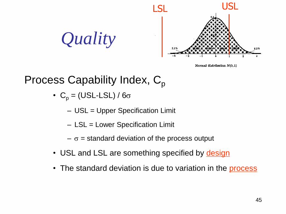
Quality
Process Capability Index, Cp
• Cp = (USL-LSL) / 6
– USL = Upper Specification Limit
– LSL = Lower Specification Limit
– = standard deviation of the process output
• USL and LSL are something specified by design
• The standard deviation is due to variation in the process
LSL USL
46
Flexibility
• Ability to accommodate different
geometries, materials, production
volumes
• Measured as D cost, D time, etc,
47
Environmental performance
• LCA Process and Product
• Enterprise Level
• Global Level
48
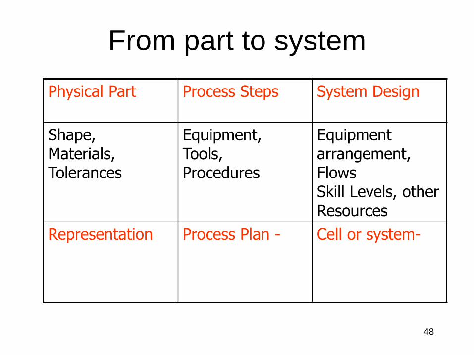
From part to system
Physical Part Process Steps System Design
Shape,Materials,Tolerances
Equipment,Tools, Procedures
Equipment arrangement,FlowsSkill Levels, other Resources
Representation Process Plan - Cell or system-
49
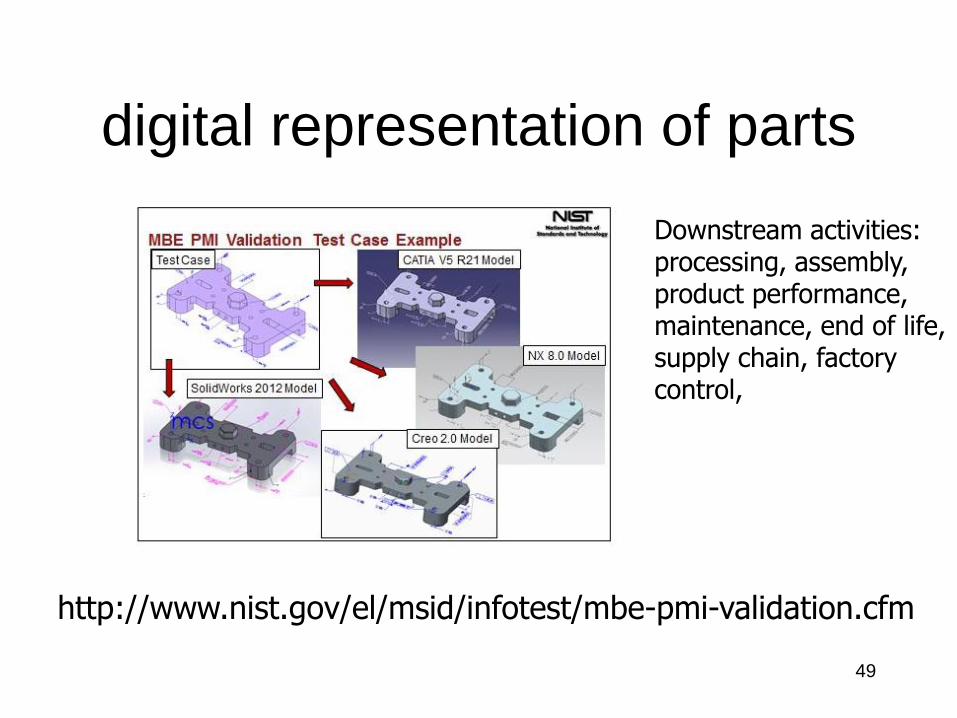
http://www.nist.gov/el/msid/infotest/mbe-pmi-validation.cfm
digital representation of parts
Downstream activities:processing, assembly, product performance,maintenance, end of life, supply chain, factory control,
50
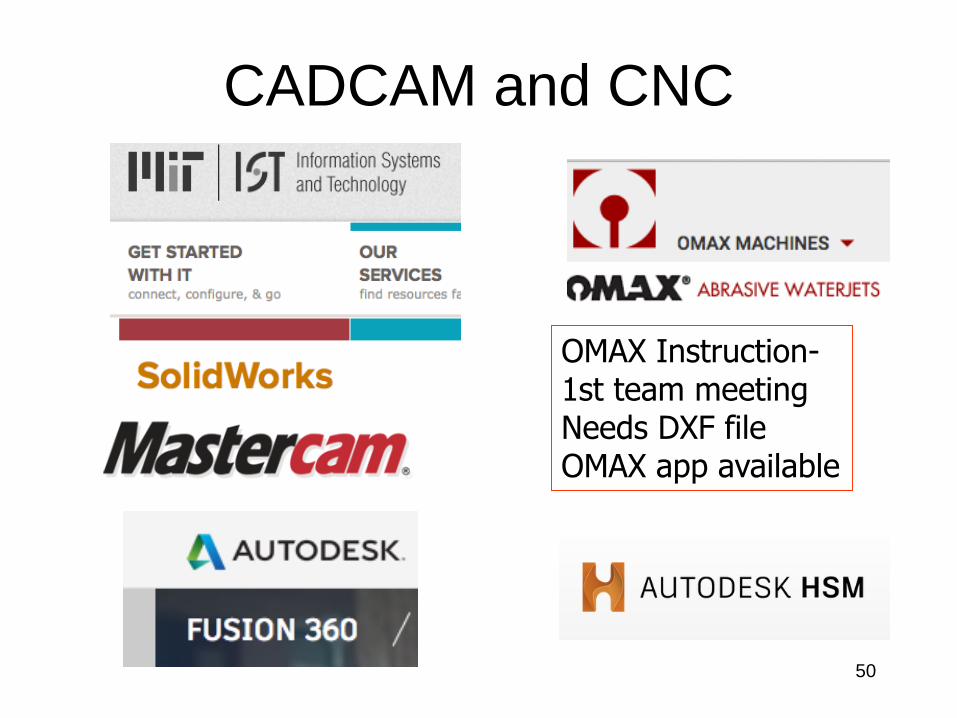
CADCAM and CNC
OMAX Instruction-1st team meetingNeeds DXF file OMAX app available
51
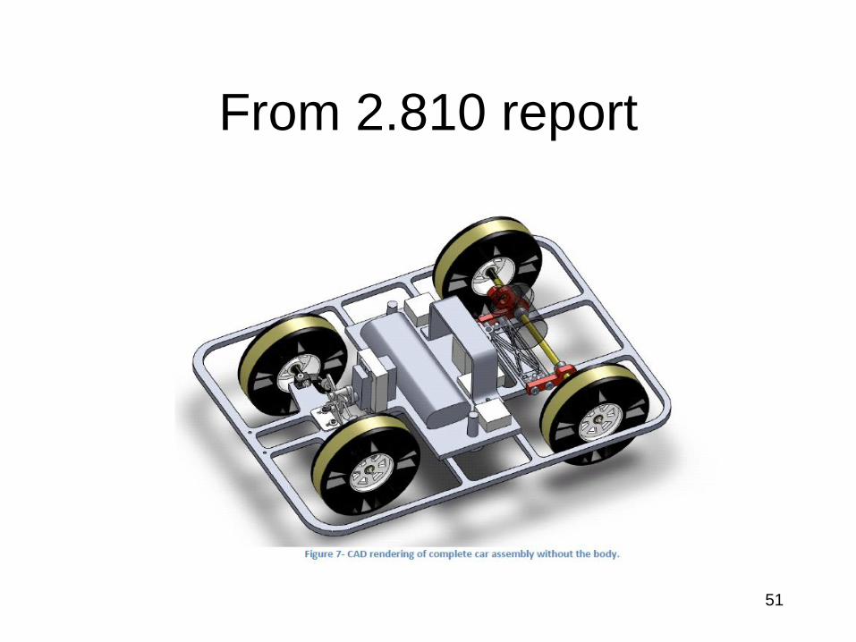
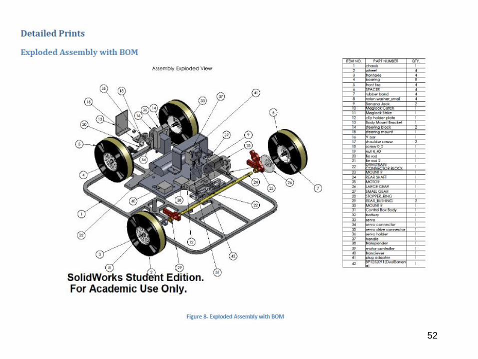
From 2.810 report
52
53
Process Planning
• Identify machines
• Tools
• Settings
• Steps required to produce a geometry
to tolerance
• Time estimation
54
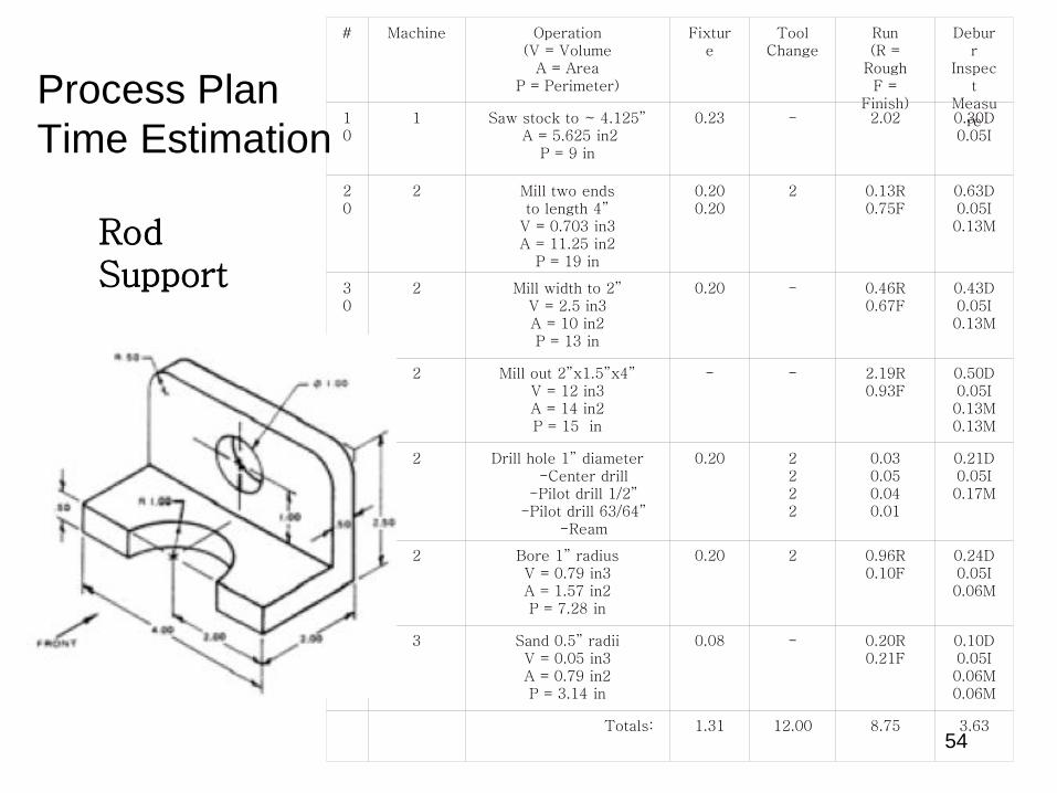
Process Plan
Time Estimation
# Machine Operation(V = Volume
A = AreaP = Perimeter)
Fixture
Tool Change
Run(R =
RoughF =
Finish)
Deburr
Inspect
Measure1
01 Saw stock to ~ 4.125”
A = 5.625 in2P = 9 in
0.23 - 2.02 0.30D0.05I
20
2 Mill two endsto length 4”
V = 0.703 in3A = 11.25 in2
P = 19 in
0.200.20
2 0.13R0.75F
0.63D0.05I0.13M
30
2 Mill width to 2”V = 2.5 in3A = 10 in2P = 13 in
0.20 - 0.46R0.67F
0.43D0.05I0.13M
40
2 Mill out 2”x1.5”x4”V = 12 in3A = 14 in2P = 15 in
- - 2.19R0.93F
0.50D0.05I0.13M0.13M
50
2 Drill hole 1” diameter-Center drill
-Pilot drill 1/2”-Pilot drill 63/64”
-Ream
0.20 2222
0.030.050.040.01
0.21D0.05I0.17M
60
2 Bore 1” radiusV = 0.79 in3A = 1.57 in2P = 7.28 in
0.20 2 0.96R0.10F
0.24D0.05I0.06M
70
3 Sand 0.5” radiiV = 0.05 in3A = 0.79 in2P = 3.14 in
0.08 - 0.20R0.21F
0.10D0.05I0.06M0.06M
Totals: 1.31 12.00 8.75 3.63
RodSupport
55
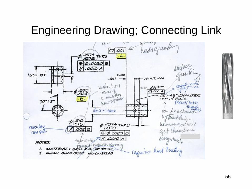
Engineering Drawing; Connecting Link
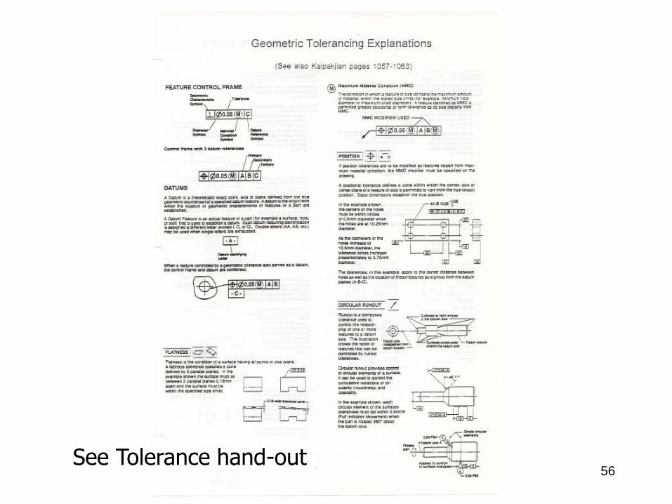
56See Tolerance hand-out
57
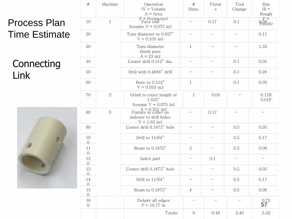
Process Plan
Time Estimate
1
3
# Machine Operation(V = Volume
A = AreaP = Perimeter)
# Dims.
Fixture
Tool Change
Run(R =
RoughF =
Finish)10 Face end
Assume V = 0.075 in3
- 0.17 0.1 0.08
20 Turn diameter to 0.827”V = 0.105 in3
- - - 0.11
30 Turn diameterfinish passA = 23 in2
1 - - 1.35
40 Center drill 0.512” dia. - - 0.1 0.05
50 Drill with 0.4688” drill - - 0.1 0.28
60 Bore to 0.512”V = 0.033 in3
1 0.1 0.05
70 2 Grind to exact length of 1.635”
Assume V = 0.075 in3
A = 0.331 in2
1 0.04 - 0.11R0.01F
80 Fixture in collet on indexer to drill holes
V = 1.65 in3
- 0.17 - -
90 Center drill 0.1875” hole - - 0.5 0.05
100
Drill to 11/64” - - 0.5 0.17
110
Ream to 0.1875” 2 - 0.5 0.06
120
Index part - 0.1 - -
130
Center drill 0.1875” hole - - 0.5 0.05
140
Drill to 11/64” - - 0.5 0.17
150
Ream to 0.1875” 4 - 0.5 0.06
160
Deburr all edgesP = 10.77 in
- - - 0.72
Totals: 9 0.48 3.40 3.32
ConnectingLink
58
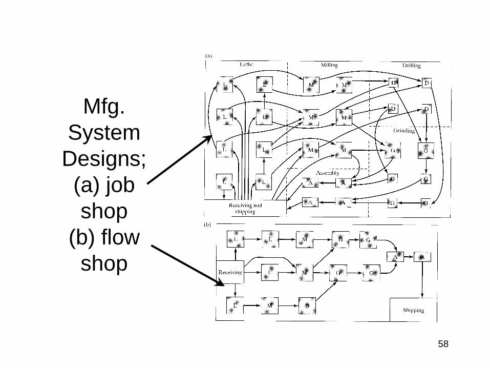
Mfg.
System
Designs;
(a) job
shop
(b) flow
shop
59
Manufacturing Systems
• Configurations
• Analysis tools (time performance)
• Historical development
• Current practice
• Future trends
60
Check List
Hand in information sheets
Fill in Google doc for labs ASAP
Attend Lab next week
Read:
1. “Competitive Attributes…”
2. “Mfg Processes and Control”
3. “Geometric Tolerancing”
4. skim Kalpakjian Ch 1-9.
Homework #1
61
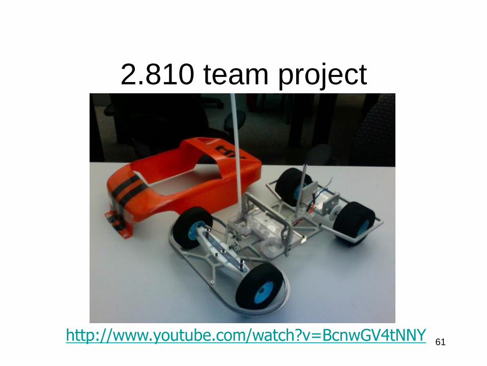
2.810 team project
http://www.youtube.com/watch?v=BcnwGV4tNNY