2a€¦ · features and benefits: • can be ordered as enclosure only, allowing for field...
TRANSCRIPT
www.crouse-hinds.com US: 1-866-764-5454 CAN: 1-800-265-0502 Copyright© 2010 Cooper Crouse-Hinds 647
2A
2ASwitchesHazardous and Non-hazardous
Description Page No.
Application/Selection see page 648
Enclosed Switches
Heavy Duty
FLS see page 652
N2RS see page 657
WST/W2ST see page 663
General Use Snap Switches
EFD, EFDC, EDS, EDSC see pages 661–662
FSPC see page 659
GUSC see page 658
Manual Contactors see page 667
Disconnect Switches
EID see page 649
EBM see page 650
NRS see pages 665–666
NST see pages 668–669
GHG see pages 653–656
Light Switch
GHG273 see page 660

www.crouse-hinds.com US: 1-866-764-5454 CAN: 1-800-265-0502 Copyright© 2010 Cooper Crouse-Hinds648
2A
2A SwitchesApplication and Selection
Quick Selector Chart
Applications:• Switches and enclosures are used in
hazardous and non-hazardous areas todisconnect motor, lighting and othercircuits and prevent arcing of theenclosed switch from igniting hazardousatmospheres.
Considerations forSelection:Enclosure Location:
• NEC/CEC and NEMA/EEMACcompliances for hazardous areas and/orwet and dirty locations
Electrical:
• Consistency with the functions to beperformed
Application:
• Selection of appropriate switch andoperating mechanism
Options:• Optional material and finishes available
for highly corrosive atmospheres• Various hub sizes are available to suit
particular applications
Quick Selector Chart
Electrical Rating
Switch
Enclosure
NEC/CEC & NEMA/EEMAC
Compliances
Max.
Amps
Max.
Volts
Max.
HP
Switch
Type
Fused or
Unfused
WST NEMA/EEMAC: 3R, 4, 12 100 600VAC250VDC
75 Visible bladeHeavy duty
Fused & unfused
EDS, EDSC,EFD, EFDC
Cl. I, Div. 1 & 2, Groups B, C, D;Cl. II, Div. 1, Groups E, F, G;Cl. II, Div. 2, Groups F, G;Cl. III;NEMA/EEMAC: 3, 7BCD, 9EFG, 12
30 277VAC 2 General use snap Unfused
FSPC Cl. I, Div. 1 & 2, Groups A, B, C, D;Cl. II, Div. 1, Groups E, F, G;Cl. II, Div. 2, Groups F, G;Cl. III;NEMA/EEMAC: 3, 7ABCD, 9EFG, 12
20 277VAC 2 General use snap Unfused
GUSC Cl. I, Div. 1 & 2, Groups C, D;Cl. II, Div. 1, Groups E, F, G;Cl. II, Div. 2, Groups F, G;Cl. III;NEMA/EEMAC: 3, 7CD, 9EFG, 12
30 600VAC 2 General use snap Unfused
FLS Cl. I, Div. 1 & 2, Groups C, D;Cl. II, Div. 1, Groups E, F, G;Cl. II, Div. 2, Groups F, G;Cl. III;NEMA/EEMAC: 3, 4, 7CD, 9EFG, 12
100 600VAC 50 Visible bladeDisconnect
Unfused
EBM Cl. I, Div. 1 & 2, Groups B, C, D;Cl. II, Div. 1, Groups E, F, G;Cl. II, Div. 2, Groups F, G;Cl. III;NEMA/EEMAC 3, 4, 7BCD, 9EFG, 12
100 600VAC 75 Visible bladeDisconnect
Fused & unfused
NRS NEMA/EEMAC: 3, 4X, 12 100 600VAC 75 Rotary - Disconnect Fused & unfused
N2RS Cl. I, Div. 2, Groups B, C, D;NEMA: 3, 4X, 12
100 600VAC 60 Rotary - Disconnect Unfused
NST NEMA: 3, 4X, 12 200 600VAC250VDC
125 Visible bladeDisconnect
Fused & unfused
ManualContactors
NEMA/EEMAC: 3R 30 600VAC 15 Contacts, snap Unfused
GHG Cl. I, Div. 2, Groups A, B, C, D;Cl. II, Div. 1, Groups E, F, G;Cl. I, Zones 1 & 2, Ex de IIB+H, Ex de IIC
180 600VAC 150 Rotary, snap Unfused
EID Cl. I, Div. 1 & 2, Groups B, C, D;Cl. I, Zones 1 & 2;Cl. II, Div. 1, Groups E, F, G;Cl. III
100 600VAC 50 Rotary - Disconnect Unfused

www.crouse-hinds.com US: 1-866-764-5454 CAN: 1-800-265-0502 Copyright© 2010 Cooper Crouse-Hinds 649
2A
2AEID Disconnect Assembly Cl. I, Div. 1 & 2, Groups B,C,DCl. I, Zones 1 & 2Cl. II, Div. 1, Groups E,F,GCl. III
UL/cUL ListedEnclosure Type 3, 3R, 4, 4X*,7BCD, 9EFG
Applications:• Provides an explosionproof disconnect
switch assembly for hazardous areaelectrical systems
• Incorporates Cooper Crouse-Hinds' highintegrity manufacturing standards forreliability and safety in a compact,space-efficient NEMA 4 enclosure
Features and Benefits:• Can be ordered as enclosure only,
allowing for field installation of switchwhile maintaining product certification
• NEMA 4X breather and drain** providesa moisture control solution in hose-downapplications
• Small, compact footprint - less mountingspace required
• Large red painted aluminum rotaryhandle operator mounted on coverassembly provides rugged, reliableperformance in the field and allows forthe position of the switch to be easilyidentified from a distance
• Neoprene cover gasket provides ULType 4 (hosetight) environmental rating
• Detachable/adjustable mounting feetprovide flexible mounting alternatives forease of installation; no need to replacethe entire enclosure if a mounting foot isbroken
• Stainless steel hinges provide easyaccess to inside of enclosure for wiringand maintenance
• (2) Conduit entries, one on top and oneon bottom (EIDA—1" NPT entries,EIDB—1 1/2" NPT entries) for easy top orbottom feed of conductors
• (2) 1/2" NPT conduit entries, one on topand one on bottom, for field addition ofbreather and/or drain or for use withauxiliary contacts; †holes come pluggedwith Cooper Crouse-Hinds PLGexplosionproof as standard
• Provides lockout/tagout capability whichcomplies with OSHA requirements,allowing for locking in the ON or OFFposition for standard maintenancechecks
• Complies with NEC Article 312 wirebending requirements for max gaugewire, allowing for easy and safeinstallation, and reliable operation ofproduct
Certifications:• Class I, Divisions 1 & 2, Groups B, C & D• Class I, Zones 1 & 2• Class II, Division 1, Groups E, F, & G• Class III• Enclosure Type 3, 3R, 4 or 4X*, 7BCD,
9EFG• UL Standard 886• cUL to CSA C22.2 No. 30
Ordering Information:Switch Rating
(amps)
Enclosure
Only
Enclosure
with Switch
30 EIDA EIDA303060 EIDA EIDA3060100 EIDB EIDB3100
Options:Description Suffix
• Auxiliary Contact (single block).... S784• Auxiliary Contacts (two blocks).... S785• Breather and Drain........................S756V• Epoxy Powder Coat Finish
(external only)................................S752• Epoxy Powder Coat Finish
(internal and external)................... S753• External Ground Lug.....................S214
Standard Materials:• Body and Cover—Copper-free
Aluminum• Gasket—Neoprene• Cover Bolts—Steel• Hinges—Stainless Steel• Mounting Plate Sheet—Aluminum• Rotary Actuating Handle—Aluminum
Standard Finishes:• Copper-free Aluminum—Natural• Steel—Electro-galvanized
Electrical Ratings:• 600 VAC• Amperages and Horse Power Ratings
AmpRating
HP Rating at:
200V 208V 240V 480V 600V
30 10 10 10 20 3060 20 20 20 40 40100 25 25 30 50 50
Weights:EIDA 36 lbs 16 kgEIDB 62 lbs 28 kg
*When ordered with S752 or S753 suffix.**When ordered with S756V suffix.†For both drains and auxiliary contacts, please contact factory.
EIDA EIDB
A 9.65" 11.75"245mm 298mm
B5" 7"127mm 178mm
C10.47" 12.53"266mm 318mm
D11.13" 15.13"283mm 384mm
E12.47" 16.53"317mm 420mm
F 2.75" 2.75"
Dimensions:
www.crouse-hinds.com US: 1-866-764-5454 CAN: 1-800-265-0502 Copyright© 2010 Cooper Crouse-Hinds650
2A
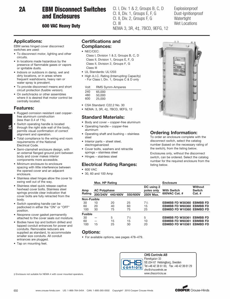
2A EBM Disconnect Switches and Enclosures600 VAC Heavy Duty
Cl. I, Div. 1 & 2, Groups B, C, DCl. II, Div. 1, Groups E, F, GCl. II, Div. 2, Groups F, GCl. IIINEMA 3, 3R, 4‡, 7BCD, 9EFG, 12
ExplosionproofDust-IgnitionproofWatertightWet Locations
Applications:EBM series hinged cover disconnectswitches are used:• To disconnect motor, lighting and other
circuits.• In locations made hazardous by the
presence of flammable gases or vaporsor ignitable dusts.
• Indoors or outdoors in damp, wet anddirty locations, or in areas wherefrequent washdowns, heavy rain orwater spray is prevalent.
• To provide disconnect means and shortcircuit protection (fusible version).
• On switchracks or other assemblieswhere it is desired that motor control becentrally located.
Features:• Rugged corrosion resistant cast copper-
free aluminum construction (less than 0.4 of 1%).
• Switch operating handle is locatedthrough the right side wall of the body,permits visual confirmation of correctalignment and operation.
• Total compliance to the wiring end roomrequirements of the National Electrical Code.
• Semi-clamshell enclosure design, withan external flanged ground joint betweenbody and cover makes interiorcomponents more accessible.
• Minimum enclosure-to-enclosurespacing with little interference betweenthe opened cover and an adjacentenclosure.
• Stainless steel hinges allow the cover toswing well out of the way.
• Stainless steel quick release captivehexhead cover bolts. Stainless steelsprings provide clear indication thatcover bolts are fully retracted from thebody.
• Switch operating handle can bepadlocked in either the "ON" or "OFF"position.
• Neoprene cover gasket permanentlyattached to the cover seals out moisture.
• Bodies have top and bottom drilled andtapped conduit entrances for power andconduits. Removable reducers aresupplied as standard, to accommodatesmaller size conduits. All conduitentrances are plugged.
• Tap on mounting feet.
Certifications andCompliances:• NEC/CEC:
Class I, Division 1 & 2, Groups B, C, DClass II, Division 1, Groups E, F, GClass II, Division 2, Groups F, GClass III
• UL Standards: UL1203• High A.I.C. Rating (Interrupting Capacity)
- For Class I, Div. 1, Groups C & D only
Volt RMS Symm-Amperes
240480600
65,00050,00025,000
• CSA Standard: C22.2 No. 30• NEMA: 3, 3R, 4‡, 7BCD, 9EFG, 12
Standard Materials:• Body and cover – copper-free aluminum• Operating handle – copper-free
aluminum• Operating shaft and bushing – stainless
steel• Interior parts – sheet steel,
electrogalvanized• Cover bolts, washers and retractile
springs – stainless steel• Hinges – stainless steel
Electrical Rating Ranges:• 600 VAC• 30, 60 and 100 Amp
Ordering Information:To order an enclosure complete with thedisconnect switch, select the catalognumber (based on the necessary rating ofthe switch), from the listing below.
Enclosures only, without the disconnectswitch, can be ordered. Select the catalognumber for the required enclosure from thelisting below.
Max. HP Rating Enclosure
Amp AC Polyphase
DC using 2
poles only With Switch
Without
SwitchRating 200/240V 440/480V 550/600V 250V Max. 600VAC Cat. # Cat. #
Non-Fusible
30 10 20 25 71/2 EBMBB FD W30360 EBMBB FD60 20 40 60 15 EBMBB FD W60360 EBMBB FD100 30 75 75 25 EBMBD FD W10360 EBMBD FD
Fusible
30 — 5 71/2 5 EBMBB FD W30361 EBMBB FD60 — 15 15 10 EBMBB FD W60361 EBMBB FD100 15 25 30 20 EBMBD FD W10361 EBMBD FD
Options:• For available options, see pages 478–479.
‡ Enclosure not suitable for NEMA 4 with cover mounted operators.

www.crouse-hinds.com US: 1-866-764-5454 CAN: 1-800-265-0502 Copyright© 2010 Cooper Crouse-Hinds 651
2A
2AEBM Disconnect Switches and Enclosures600 VAC Heavy Duty
Cl. I, Div. 1 & 2, Groups B, C, DCl. II, Div. 1, Groups E, F, GCl. II, Div. 2, Groups F, GCl. IIINEMA 3, 3R, 4‡, 7BCD, 9EFG, 12
ExplosionproofDust-IgnitionproofWatertightWet Locations
DimensionsIn Inches:
Dimensions are approximate, not for construction purposes.*1" D & T conduit entry for control conductors supplied with PLG plug top and bottom.
**Conduit entrance(s) for power conductors (top and bottom). (All conduit entrance(s) supplied with RE reducer and PLG plug.)
Enclosure
Only
Enclosure
Size
**J Conduit
Entry Trade
SizeCat. # Symbol A B C D E F G D&T† w/RE K L M P
30 and 60Amp Frame EBMBB B 25.75 24.75 26.90 6.00 13.03 14.46 10.25 2" 1.5" 3.25 3.13 10.25 22.00
100 AmpFrame EBMBD D 28.25 27.25 29.40 6.00 13.03 14.46 10.25 3" 2.5" 3.25 3.13 10.25 24.50
‡ Enclosure not suitable for NEMA 4 with cover mounted operators. †Drilled & Tapped.
www.crouse-hinds.com US: 1-866-764-5454 CAN: 1-800-265-0502 Copyright© 2010 Cooper Crouse-Hinds652
2A
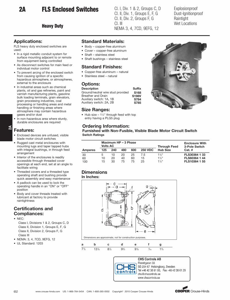
2A FLS Enclosed Switches
Heavy Duty
Cl. I, Div. 1 & 2, Groups C, DCl. II, Div. 1, Groups E, F, GCl. II, Div. 2, Groups F, GCl. IIINEMA 3, 4, 7CD, 9EFG, 12
ExplosionproofDust-IgnitionproofRaintightWet Locations
Applications:FLS heavy duty enclosed switches areused:• In a rigid metallic conduit system for
surface mounting adjacent to or remotefrom equipment being controlled
• As disconnect switches for main feed orindividual motor control
• To prevent arcing of the enclosed switchfrom causing ignition of a specifichazardous atmosphere, or atmospheres,external to the enclosure
• In industrial areas such as chemicalplants, oil and gas refineries, paint andvarnish manufacturing plants, gasolinebulk loading terminals, grain elevators,grain processing industries, coalprocessing or handling areas and metalhandling or finishing areas whereatmosphere may contain hazardousgases and/or dust
• In non-hazardous area where sturdy,durable enclosures are required
Features:• Enclosed devices are unfused, visible
blade motor circuit switches• Rugged cast metal enclosures with
mounting lugs and taper tapped hubswith integral bushings, in through feedarrangement
• Interior of the enclosures is readilyaccessible through threaded coveropenings at each end, set at an angle tofacilitate wiring
• Threaded covers and a threaded typeoperating shaft and bushing providequick assembly and easy maintenance
• A padlock can be used to lock theoperating handle in an "ON" or "OFF"position
• Body and cover threads treated withlubricant at factory to provideraintightness
Certifications andCompliances:• NEC:
Class I, Divisions 1 & 2, Groups C, DClass II, Division 1, Groups E, F, GClass II, Division 2, Groups F, GClass III
• NEMA: 3, 4, 7CD, 9EFG, 12• UL Standard: 1203
Standard Materials:• Body – copper-free aluminum• Cover – copper-free aluminum• Shaft – stainless steel• Shaft bushings – stainless steel
Standard Finishes:• Copper-free aluminum – natural• Stainless steel – natural
Options:Description Suffix
Ground/neutral wire stud provided S168Breather and Drain S198VAuxiliary switch: 1A, 1B S784Auxiliary switch: 2A, 2B S785
Size Ranges:• Hub size – 11/2" through feed with top
entry having a PLG5 plug
Ordering Information:Furnished with Non-Fusible, Visible Blade Motor Circuit SwitchSwitch Ratings
Maximum HP – 3 Phase
Volts ACEnclosure With
3-Pole SwitchAmperes 125 240 480 600 250 VDC
Through Feed
Hub Size Cat. #
30 5 10 20 25 7.5 11/2" FLS30364 1 33
60 10 20 40 60 15 11/2" FLS60364 1 44
100 15 30 75 75 25 11/2" FLS10364 1 55
DimensionsIn Inches:
Dimensions are approximate, not for construction purposes.
a b c d e f g
71/2 131/8 81/2 93/4 91/87/16 13/4
www.crouse-hinds.com US: 1-866-764-5454 CAN: 1-800-265-0502 Copyright© 2010 Cooper Crouse-Hinds 653
2A
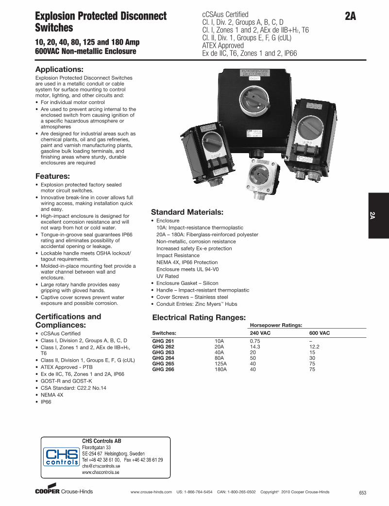
2AExplosion Protected DisconnectSwitches10, 20, 40, 80, 125 and 180 Amp600VAC Non-metallic Enclosure
cCSAus CertifiedCl. I, Div. 2, Groups A, B, C, DCl. I, Zones 1 and 2, AEx de IIB+H2, T6Cl. II, Div. 1, Groups E, F, G (cUL)ATEX ApprovedEx de IIC, T6, Zones 1 and 2, IP66
Applications:Explosion Protected Disconnect Switchesare used in a metallic conduit or cablesystem for surface mounting to controlmotor, lighting, and other circuits and:• For individual motor control• Are used to prevent arcing internal to the
enclosed switch from causing ignition ofa specific hazardous atmosphere oratmospheres
• Are designed for industrial areas such aschemical plants, oil and gas refineries,paint and varnish manufacturing plants,gasoline bulk loading terminals, andfinishing areas where sturdy, durableenclosures are required
Features:• Explosion protected factory sealed
motor circuit switches.• Innovative break-line in cover allows full
wiring access, making installation quickand easy.
• High-impact enclosure is designed forexcellent corrosion resistance and willnot warp from hot or cold water.
• Tongue-in-groove seal guarantees IP66rating and eliminates possibility ofaccidental opening or leakage.
• Lockable handle meets OSHA lockout/tagout requirements.
• Molded-in-place mounting feet provide awater channel between wall andenclosure.
• Large rotary handle provides easygripping with gloved hands.
• Captive cover screws prevent waterexposure and possible corrosion.
Certifications andCompliances:• cCSAus Certified• Class I, Division 2, Groups A, B, C, D• Class I, Zones 1 and 2, AEx de IIB+H2,
T6• Class II, Division 1, Groups E, F, G (cUL)• ATEX Approved - PTB• Ex de IIC, T6, Zones 1 and 2A, IP66• GOST-R and GOST-K• CSA Standard: C22.2 No.14• NEMA 4X• IP66
Electrical Rating Ranges:Horsepower Ratings:
Switches: 240 VAC 600 VAC
GHG 261 10A 0.75 –GHG 262 20A 14.3 12.2GHG 263 40A 20 15GHG 264 80A 50 30GHG 265 125A 40 75GHG 266 180A 40 75
Standard Materials:• Enclosure
10A: Impact-resistance thermoplastic20A – 180A: Fiberglass-reinforced polyesterNon-metallic, corrosion resistanceIncreased safety Ex-e protectionImpact ResistanceNEMA 4X, IP66 ProtectionEnclosure meets UL 94-V0UV Rated
• Enclosure Gasket – Silicon• Handle – Impact-resistant thermoplastic• Cover Screws – Stainless steel• Conduit Entries: Zinc Myers™ Hubs

www.crouse-hinds.com US: 1-866-764-5454 CAN: 1-800-265-0502 Copyright© 2010 Cooper Crouse-Hinds654
2A
2A Explosion Protected DisconnectSwitches10, 20, 40, 80, 125 and 180 Amp600VAC Non-metallic Enclosure
cCSAus CertifiedCl. I, Div. 2, Groups A, B, C, DCl. I, Zones 1 and 2, AEx de IIB+H2, T6Cl. II, Div. 1, Groups E, F, G (cUL)ATEX ApprovedEx de IIC, T6, Zones 1 and 2, IP66
Ordering Information:10 AMP 20 AMP 40 AMP
Pole 3 Pole 3 Pole 6 Pole 3 Pole 6 Pole
Rated Voltage 500 V 690 V 690 V 690 V 690 V
Auxiliary Contact1 NO, making – laggingbreaking – leading
1 NO, making – laggingbreaking – leading 1 NC 1 NO, making – lagging
breaking – leading 1 NC
Auxiliary
Connection
14 AWG2 x 2.5 mm2
12 AWG2 x 4 mm2
12 AWG2 x 4 mm2
12 AWG2 x 16 mm2
12 AWG2 x 16 mm2
Connection
Terminals14 AWG 12 AWG 12 AWG 6 AWG 6 AWG
Conduit Entries 1 x 3/4" 2 x 3/4" 2 x 3/4" 2 x 3/4" 2 x 1"
Cat. # GHG 261 0005 L0002 GHG 262 2301 L0003 GHG 262 2601 L0002 GHG 263 2301 L0002 GHG 263 0050 L0002
Weight 0.55 kg 1.2 lbs. 1.5 kg 3.3 lbs. 2.3 kg 5.1 lbs. 2.3 kg 5.1 lbs. 6.5 kg 14.3 lbs.
Dimensions See Figure 1 See Figure 2 See Figure 3 See Figure 4 See Figure 5
Wall Mounting
PlateGHG6101953R0101 GHG 610 1953 R0104 GHG 610 1953 R0118 GHG 610 1953 R0118 not required
80 AMP 125 AMP 180 AMP
Pole 3 Pole 6 Pole 3 Pole 3 Pole
Rated Voltage 690 V 690 V 690 V 690 V
Auxiliary Contact1 NO, making – laggingbreaking – leading 1 NC 1 NO, making – lagging
breaking – leading1 NO, making – laggingbreaking – leading
Auxiliary Connection12 AWG2 x 50 mm2
12 AWG2 x 50 mm2
12 AWG1 x 70 mm2
12 AWG1 x 120 mm2
Connection Terminals 2 AWG 2 AWG 2 / 0 AWG 4 / 0 AWG
Conduit Entries 1 x 11/2" 2 x 11/2" 2 x 11/2" 2 x 2"
Cat. # GHG 264 0020 L0002 GHG 264 0021 L0002 GHG 265 0010 L0003 GHG 266 0006 L0002
Weight 6.5 kg 14.3 lbs. 9.0 kg 19.8 lbs. 16.0 kg 35.2 lbs. 16.5 kg 36.3 lbs.
Dimensions See Figure 6 See Figure 7 See Figure 8 See Figure 8
Wall Mounting Plate not required not required not required not required
For Variable Speed, Three Phase Drives20 AMP 40 AMP 80 AMP
Pole 3 Pole 3 Pole 3 Pole
Rated Voltage 690 V 690 V 690 V
Auxiliary Contact1 NO, making – laggingbreaking – leading
1 NO, making – laggingbreaking – leading
1 NO, making – laggingbreaking – leading
Auxiliary Connection12 AWG2 x 4 mm2
6 AWG2 x 16 mm2
2 AWG2 x 35 mm2
Connection
Terminals12 AWG 6 AWG 2 AWG
Conduit Entries 2 x 3/4" 1 x 1" + 1 x 1/2" 1 x 11/2" + 1 x 1/2"
Cat. # GHG 262 0014 L0001 GHG 263 0053 L0001 GHG 264 0024 L0001
Weight 1.6 kg 3.5 lbs. 2.3 kg 5.1 lbs. 3.5 kg 7.7 lbs.
Dimensions See Figure 9 See Figure 10 See Figure 11
Wall Mounting Plate GHG 610 1953 R0118 GHG 610 1953 R0118 GHG6101953R0110
Switches can be mounted directly onto a wall. The optional wall mounting plate offers a more convenient method of mounting.

www.crouse-hinds.com US: 1-866-764-5454 CAN: 1-800-265-0502 Copyright© 2010 Cooper Crouse-Hinds 655
2A
DimensionsIn Inches:
Figure 1 - 10 Amp, 3 Pole
Figure 2 - 20 Amp, 3 Pole Figure 3 - 20 Amp, 6 Pole
Figure 4 - 40 Amp, 3 Pole Figure 5 - 40 Amp, 6 Pole
Explosion Protected DisconnectSwitches10, 20, 40, 80, 125 and 180 Amp600VAC Non-metallic Enclosure
cCSAus CertifiedCl. I, Div. 2, Groups A, B, C, DCl. I, Zones 1 and 2, AEx de IIB+H2, T6Cl. II, Div. 1, Groups E, F, G (cUL)ATEX ApprovedEx de IIC, T6, Zones 1 and 2, IP66
Figure 6 - 80 Amp, 3 Pole Figure 7 - 80 Amp, 6 Pole
www.crouse-hinds.com US: 1-866-764-5454 CAN: 1-800-265-0502 Copyright© 2010 Cooper Crouse-Hinds656
2A
2A Explosion Protected DisconnectSwitches10, 20, 40, 80, 125 and 180 Amp600VAC Non-metallic Enclosure
cCSAus CertifiedCl. I, Div. 2, Groups A, B, C, DCl. I, Zones 1 and 2, AEx de IIB+H2, T6Cl. II, Div. 1, Groups E, F, G (cUL)ATEX ApprovedEx de IIC, T6, Zones 1 and 2, IP66
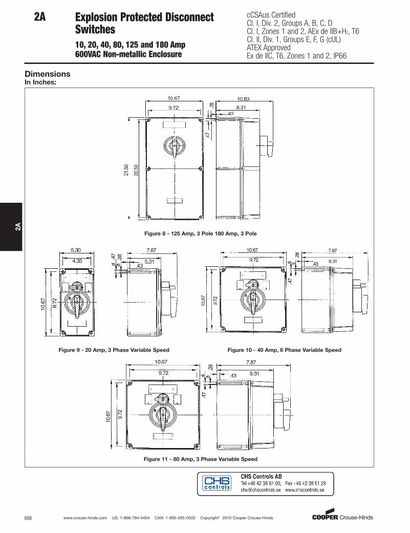
DimensionsIn Inches:
Figure 8 - 125 Amp, 3 Pole 180 Amp, 3 Pole
Figure 9 - 20 Amp, 3 Phase Variable Speed Figure 10 - 40 Amp, 6 Phase Variable Speed
Figure 11 - 80 Amp, 3 Phase Variable Speed

www.crouse-hinds.com US: 1-866-764-5454 CAN: 1-800-265-0502 Copyright© 2010 Cooper Crouse-Hinds 657
2A
2AN2RS Enclosed Switches
Heavy-Duty
Cl. I, Div. 2, Groups B, C, DNEMA 3, 4X, 7 (B, C, D Div. 2), 12WatertightDust-tightFactory Sealed
Applications:N2RS heavy-duty enclosed switches areused:• In a rigid metallic conduit or cable
system for surface mounting adjacent toor remote from equipment beingcontrolled.
• For individual motor control.• To prevent arcing internal to the
enclosed switch from causing ignition ofa specific hazardous atmosphere, oratmospheres.
• In industrial areas such as chemicalplants, oil and gas refineries, paint andvarnish manufacturing plants, gasolinebulk loading terminals, and finishingareas where atmospheres may containhazardous gases.
• In non-hazardous areas where sturdy,durable enclosures are required.
• When controlling motor, lighting andother circuits.
Features:• Enclosed devices are unfused, factory
sealed motor circuit switches.• Exceeds NEC® wiring end room
requirements for ease of installation.• RSWP factory sealed industrial control
switch, no external seals are required.• Enclosure is made of Krydon® high-
impact strength fiberglass-reinforcedpolyester material having excellentcorrosion resistance and stability to heat.
• Krydon material hubs with integralbushings, for dead-end or through-feedarrangements are supplied.
• Krydon material mounting feet supplied.• Suitable for wash down and corrosive
areas (Type 4X).• A padlock can be used to lock the
operating handle in the "OFF" position.• Rotary actuator with snap action.• Unitized, strong and durable
construction provides longer service lifefor equipment.
• Factory sealed 10A, 600 VAC auxiliarycontact switch provided.
Standard Materials:• Enclosure – Krydon material• External Hardware – Stainless Steel• Operating Handle – Nylon
Size Ranges:• Hub size:
(2) 11/2" (30, 60 amps)(2) 21/2" (100 amps)
Krydon material hubs included (notmounted)
Ordering InformationFurnished with Non-Fusible, Factory Sealed Motor Circuit SwitchSwitch Ratings
Maximum HP – 3 Phase Volts AC Enclosure with 3-Pole Switch
Amperes 240 480 600 Hub Size Cat. #
30 10 20 25 11/2" N2RS60360 15 30 40 11/2" N2RS603100 20 40 60 21/2" N2RS1003
DimensionsIn Inches:
Certifications andCompliances:• NEC:
Class I, Division 2, Groups B, C, D• NEMA: 3, 4X, 7 (B, C, D Div. 2), 12• UL Standard: 508, 1604• cUL to CSA Standard C22.2 No.213• IP65
www.crouse-hinds.com US: 1-866-764-5454 CAN: 1-800-265-0502 Copyright© 2010 Cooper Crouse-Hinds658
2A
2A GUSC Enclosures
with General Use Snap Switches
Cl. I, Div. 1 & 2, Groups C, DCl. II, Div. 1, Groups E, F, GCl. II, Div. 2, Groups F, GCl. IIINEMA 3, 7CD, 9EFG, 12
ExplosionproofDust-IgnitionproofRaintightWet Locations
Applications:GUSC snap switches are used:• In a rigid metallic conduit system for
surface mounting adjacent to or remotefrom the equipment being controlled
• To prevent arcing of the enclosedswitches from causing ignition of aspecific hazardous atmosphere, oratmospheres, external to the enclosure
• In industrial areas such as chemicalplants, oil and gas refineries, paint andvarnish manufacturing plants, gasolinebulk loading terminals, grain elevators,grain processing industries, coalprocessing or handling areas, or metalhandling or finishing areas where theatmosphere may contain hazardousgases and/or dust
• In non-hazardous areas where sturdy,durable enclosures are required
Features:• Enclosures are of rugged metal
construction with mounting lugs andtaper tapped hubs with integralbushings, in a through feed or bottomfeed arrangement, for connection to therigid metallic conduit
• Cover is threaded, which provides forfast and proper assembly
• Provided with a threaded operating shaftand bushing
• Provision is made to use a padlock with1/4" hasp, to lock the operating lever in an "ON" or "OFF" position
• Body and cover threads treated withlubricant at factory to provideraintightness
Certifications andCompliances:• NEC/CEC:
Class I, Div. 1 & 2, Groups C, DClass II, Div. 1, Groups E, F, GClass II, Div. 2, Groups F, GClass III
• NEMA/EEMAC: 3, 7CD, 9EFG, 12• UL Standard: 1203• CSA Standard: C22.2, No. 30
Standard Materials:• Body – Feraloy® iron alloy• Cover – copper-free aluminum• Shaft – stainless steel• Shaft bushing – stainless steel
Standard Finishes:• Feraloy iron alloy – electrogalvanized and
aluminum acrylic paint• Copper-free aluminum – natural• Stainless steel – natural
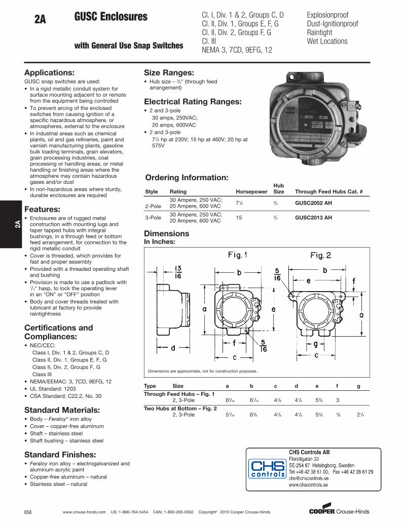
Size Ranges:• Hub size – 3/4" (through feed
arrangement)
Electrical Rating Ranges:• 2 and 3-pole
30 amps, 250VAC;20 amps, 600VAC
• 2 and 3-pole71/2 hp at 230V; 15 hp at 460V; 20 hp at575V
Ordering Information:
Style Rating Horsepower
Hub
Size Through Feed Hubs Cat. #
2-Pole30 Ampere, 250 VAC;20 Ampere, 600 VAC 71/2
3/4 GUSC2052 AH
3-Pole 30 Ampere, 250 VAC;20 Ampere, 600 VAC 15 3/4 GUSC2013 AH
DimensionsIn Inches:
Dimensions are approximate, not for construction purposes.
Type Size a b c d e f g
Through Feed Hubs – Fig. 1
2, 3-Pole 63/16 61/16 47/8 41/8 53/8 3
Two Hubs at Bottom – Fig. 2
2, 3-Pole 57/16 63/8 47/8 41/8 55/83/8 21/4

www.crouse-hinds.com US: 1-866-764-5454 CAN: 1-800-265-0502 Copyright© 2010 Cooper Crouse-Hinds 659
2A
2AFSPC Enclosures
with General Use Snap Switches
Cl. I, Div. 1 & 2, Groups A†, B, C, DCl. II, Div. 1, Groups E, F, GCl. II, Div. 2, Groups F, GCl. IIINEMA 3, 7A†BCD, 9EFG, 12
ExplosionproofDust-IgnitionproofRaintightWet Locations
Applications:FSPC snap switches are installed in a rigidmetallic conduit system for surfacemounting adjacent to or remote fromequipment being controlled and are used:• To prevent arcing of enclosed switch
from causing ignition of a specifichazardous atmosphere or atmospheresexternal to the enclosure
• In industrial areas such as chemicalplants, oil and gas refineries, paint andvarnish manufacturing plants, gasolinebulk loading terminals, grain elevators,grain processing industries, coalprocessing or handling areas, or metalhandling or finishing areas whereatmosphere may contain hazardousgases and/or dust
• In non-hazardous areas where sturdy,durable enclosures are required
Features:• Rugged cast metal enclosure with
mounting lugs and taper tapped hubswith integral bushings, in a through feedarrangement.
• Threaded cover to provide fast, properassembly and easier maintenance.
• Journalled type operating shaft – closetolerance fit for flametightness.
• Body and cover threads treated withlubricant at factory to provideraintightness.
Certifications andCompliances:• NEC:
FSPC 21 series –Class I, Divisions 1 & 2, Groups C, DClass II, Division 1, Groups E, F, GClass II, Division 2, Groups F, GClass III
• NEMA: 3, 7CD, 9EFG, 12• NEC:
FSPC 216 series –Class I, Divisions 1 & 2, Groups A, B, C, DClass II, Division 1, Groups E, F, GClass II, Division 2, Groups F, GClass III
• NEMA: 3, 7ABCD, 9EFG, 12• UL Standard: 1203• CEC:
FSPC 216 series –Class I, Divisions 1 & 2, Groups C, DClass II, Division 1, Groups E, F, GClass II, Division 2, Groups F, GClass III
• Encl. 3, 5• CSA Standard C22.2, No. 30
Standard Materials:• Body – Feraloy® iron alloy• Cover – copper-free aluminum• Shaft – stainless steel• Bushing – stainless steel
Standard Finishes:• Feraloy iron alloy – electrogalvanized
and aluminum acrylic paint• Copper-free aluminum – natural• Stainless steel – natural
†Suitable for Groups A & B usage.‡30A, 250 VAC; 20A, 600 VAC.§See page 661 for AC-rated switch information.
DimensionsIn Inches:
Dimensions are approximate, not for construction purposes.
Ordering Information:Switch Information Enclosure with Switch
AmperesHub Size Style 120VAC§ 277VAC§ Cat. # Cat. # †
3/4 1-pole 20 20 FSPC21 FSPC2163/4 2-pole 20 20 FSPC22 FSPC2263/4 3-pole ‡ ‡ FSPC230 FSPC23063/4 3-way 20 20 FSPC23 FSPC236

www.crouse-hinds.com US: 1-866-764-5454 CAN: 1-800-265-0502 Copyright© 2010 Cooper Crouse-Hinds660
2A
2A Light Switch cCSAus CertifiedCl. I, Div. 2, Groups A, B, C, DCl. II, Div. 1, Groups E, F, GCl. II, Div. 2, Groups F, G
Cl. I, Zone 1 & 2 Ex de IIC T6Cl. I, Zone 1 & 2 AEx de IIC T6
Applications:GHG273 series of switches are used:• To prevent arcing of enclosed switch
from causing ignition of a specifichazardous atmosphere external to theenclosure
• In Division 2, Zone 1 and Zone 2industrial areas such as: chemical plants,oil and gas refineries, paint and varnishmanufacturing plants, gasoline bulkloading terminals, grain elevators andprocessing industries, coal processing orhandling areas, or finishing areas whereatmosphere may contain hazardousgases and/or dust
• In non-hazardous areas where sturdy,durable enclosures are required for bothindoor and outdoor installations of lightswitches
Features:• Small and compact in design.• Large grounding plate.• Captive cover screws.• Protective collar for inadvertent
operation.• Large actuator surface allows for
operation while wearing work gloves.• Labyrinth seal to guarantee the degree
of protection IP66.• The toggle has a luminescent label to
locate switch in dark areas.• Cable entry from the top is made
possible by turning the base.
Certifications andCompliances:• cCSAus Listed• Class I, Division 2, Groups A, B, C, D• Class II, Division 1, Groups E, F, G• Class II, Division 1, Groups F, G• Class I, Zone 1 & 2, EEx de IIC T6• Class I, Zone 1 & 2, AEx de IIC T6• Class I, Zone 1 & 2, Ex de IIC T6• PTB Certificate of Conformity
Ex-91.C.1017• IP66
Standard Materials:• Body and cover – low temperature,
impact-resistant thermoplastic• Shaft and screws – stainless steel• Grounding plate – brass
Standard Finishes:• Thermoplastic – natural• Stainless steel – natural• Brass – nickel plate
Electrical Ratings:Voltage 250VAC 50 / 60 HzCurrent 16 Amps
Ordering InformationCat. # Contact Arrangement Description Entry Size
GHG 273 2000 L0005 2-pole 1 x 1/2" NPTGHG 273 2000 L0006 2-pole 1 x 3/4" NPT
GHG 273 6000 L0001 3-way 1 x 1/2" NPTGHG 273 6000 L0002 3-way 1 x 3/4" NPT
DimensionsIn Inches:
Dimensions are approximate, not for construction purposes.
www.crouse-hinds.com US: 1-866-764-5454 CAN: 1-800-265-0502 Copyright© 2010 Cooper Crouse-Hinds 661
2A
2AEDS and EFD Enclosures
with General Use Snap SwitchesFront Operated
Cl. I, Div. 1 & 2, Groups B*, C, DCl. II, Div. 1, Groups E, F, GCl. II, Div. 2, Groups F, GCl. IIINEMA 3, 7B*CD, 9EFG, 12
ExplosionproofDust-IgnitionproofRaintightWet Locations
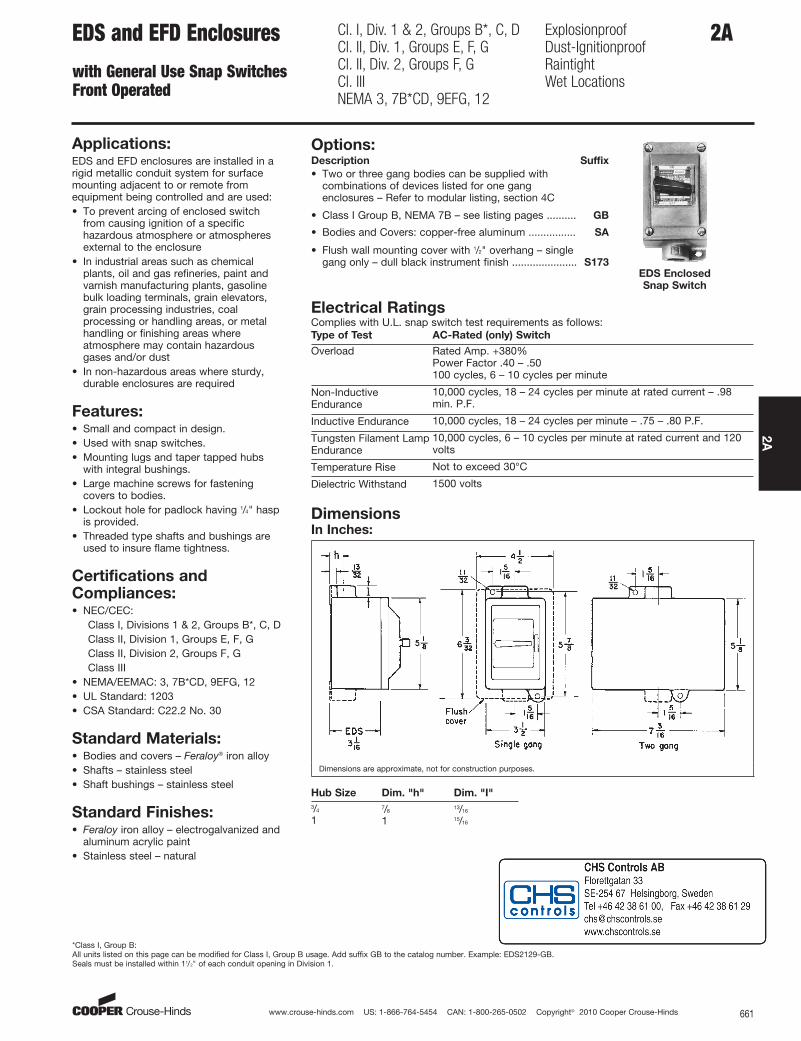
EDS Enclosed
Snap Switch
Applications:EDS and EFD enclosures are installed in arigid metallic conduit system for surfacemounting adjacent to or remote fromequipment being controlled and are used:• To prevent arcing of enclosed switch
from causing ignition of a specifichazardous atmosphere or atmospheresexternal to the enclosure
• In industrial areas such as chemicalplants, oil and gas refineries, paint andvarnish manufacturing plants, gasolinebulk loading terminals, grain elevators,grain processing industries, coalprocessing or handling areas, or metalhandling or finishing areas whereatmosphere may contain hazardousgases and/or dust
• In non-hazardous areas where sturdy,durable enclosures are required
Features:• Small and compact in design.• Used with snap switches.• Mounting lugs and taper tapped hubs
with integral bushings.• Large machine screws for fastening
covers to bodies.• Lockout hole for padlock having 1/4" hasp
is provided.• Threaded type shafts and bushings are
used to insure flame tightness.
Certifications andCompliances:• NEC/CEC:
Class I, Divisions 1 & 2, Groups B*, C, DClass II, Division 1, Groups E, F, GClass II, Division 2, Groups F, GClass III
• NEMA/EEMAC: 3, 7B*CD, 9EFG, 12• UL Standard: 1203• CSA Standard: C22.2 No. 30
Standard Materials:• Bodies and covers – Feraloy® iron alloy• Shafts – stainless steel• Shaft bushings – stainless steel
Standard Finishes:• Feraloy iron alloy – electrogalvanized and
aluminum acrylic paint• Stainless steel – natural
Options:Description Suffix
• Two or three gang bodies can be supplied withcombinations of devices listed for one gangenclosures – Refer to modular listing, section 4C
• Class I Group B, NEMA 7B – see listing pages .......... GB
• Bodies and Covers: copper-free aluminum ................ SA
• Flush wall mounting cover with 1/2" overhang – singlegang only – dull black instrument finish ...................... S173
Electrical RatingsComplies with U.L. snap switch test requirements as follows:Type of Test AC-Rated (only) Switch
Overload Rated Amp. +380%Power Factor .40 – .50100 cycles, 6 – 10 cycles per minute
Non-InductiveEndurance
10,000 cycles, 18 – 24 cycles per minute at rated current – .98min. P.F.
Inductive Endurance 10,000 cycles, 18 – 24 cycles per minute – .75 – .80 P.F.
Tungsten Filament LampEndurance
10,000 cycles, 6 – 10 cycles per minute at rated current and 120volts
Temperature Rise Not to exceed 30°C
Dielectric Withstand 1500 volts
DimensionsIn Inches:
Dimensions are approximate, not for construction purposes.
Hub Size Dim. "h" Dim. "I"
3/4 7/813/16
1 1 15/16
*Class I, Group B:All units listed on this page can be modified for Class I, Group B usage. Add suffix GB to the catalog number. Example: EDS2129-GB.Seals must be installed within 11/2" of each conduit opening in Division 1.

www.crouse-hinds.com US: 1-866-764-5454 CAN: 1-800-265-0502 Copyright© 2010 Cooper Crouse-Hinds662
2A
Dead end Through feed
Ordering Information:Amperes§ Single Gang
Replacement
Factory Sealed
Switch
Two Gang ■
Hub Size Style 120VAC 277VAC
Dead End
Cat. #
Through Feed
Cat. #
Dead End
Cat. #
Through Feed
Cat. #
3/4 1-pole 20 20 EDS2129 EDSC2129† SW5 EDS2229 EDSC2229†3/4 2-pole 20 20 EDS218 EDSC218† SW6 EDSC228†3/4 3-pole ‡ ✪ ‡ EDS2123 EDSC2123 0206500 EDSC22233/4 3-way 20 20 EDS2130 EDSC2130 SW7 EDS2230 EDSC22303/4 4-way 20 20 EDS2140 EDSC2140 SW8 EDSC2240
1 1-pole 20 20 EDS3129 EDSC3129† SW5 EDS3229 EDSC3229†1 2-pole 20 20 EDS318 EDSC318† SW6 EDS328 EDSC328†1 3-pole ‡ ✪ ‡ EDS3123 EDSC3123 0206500 EDSC32231 3-way 20 20 EDS3130 EDSC3130 SW7 EDS3230 EDSC3230
1 4-way 20 20 EDS3140 EDSC3140 SW8 EDS3240 EDSC32401 1-pole 30 ✪ 30 EFD3591 EFDC3591† AH3991* EFD3691 EFDC3691†1 2-pole 30 ✪ 30 EFD3593 EFDC3593† AH3992* EFDC3693†1 3-way 30 ✪ 30 EFD3594 EFDC3594 AH3993* EFD3694 EFDC3694
2A EDS and EFD Enclosures
with General Use Snap SwitchesFront Operated
Cl. I, Div. 1 & 2, Groups B*, C, DCl. II, Div. 1, Groups E, F, GCl. II, Div. 2, Groups F, GCl. IIINEMA 3, 7B*CD, 9EFG, 12
ExplosionproofDust-IgnitionproofRaintightWet Locations
*Class I, Group B:All units listed on this page can be modified for Class I, Group B usage. Add suffix GB to the catalog number. Example: EDS2129-GB.Seals must be installed within 11/2" of each conduit opening in Division 1.†ON-OFF standard marking for 1-pole and 2-pole units‡15A, 125 VAC; 10A, 250 VAC§See page 661 for AC-rated switch information.■Combinations of switches can be furnished.*Purchase from Cooper Wiring Devices.✪ Not factory sealed
www.crouse-hinds.com US: 1-866-764-5454 CAN: 1-800-265-0502 Copyright© 2010 Cooper Crouse-Hinds 663
2A
2AWST Enclosed SwitchesHeavy Duty30, 60, 100 Amp
NEMA 3R, 4, 12Wet LocationsWatertight
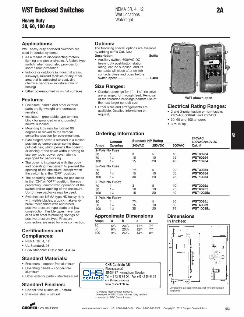
WST shown open
Applications:WST heavy duty enclosed switches areused in conduit systems:• As a means of disconnecting motors,
lighting and power circuits. A fusible typeswitch, when used, also provides forshort circuit protection
• Indoors or outdoors in industrial areas,subways, railroad facilities or any otherarea that is subjected to dust, dirt,chemical vapors or moisture (rain orhosing)
• Either pole-mounted or on flat surfaces
Features:• Enclosure, handle and other exterior
parts are lightweight and corrosionresistant.
• Insulated – groundable type terminalblock for grounded or ungroundedneutral supplied.
• Mounting lugs may be rotated 90degrees or moved to the verticalcenterline position for pole-mounting.
• Side hinged cover is retained in a closedposition by compression spring draw-pull catches, which permits the openingor closing of the cover without having touse any tools. Lower cover latch isequipped for padlocking.
• The cover is interlocked with the bodyand operating mechanism to prevent theopening of the enclosure, except whenthe switch is in the "OFF" position.
• The operating handle may be padlockedin the "ON" or "OFF" position, therebypreventing unauthorized operation of theswitch and/or opening of the enclosure.Up to three padlocks may be used.
• Switches are NEMA type HD heavy dutywith visible blades, a quick make-and-break mechanism with reinforced,positive pressure-type blade and jawconstruction. Fusible types have fuseclips with steel reinforcing springs ofpositive pressure type. Pressureconnectors are used for wire connection.
Certifications andCompliances:• NEMA: 3R, 4, 12• UL Standard: 98• CSA Standard: C22.2 Nos. 4 & 14
Standard Materials:• Enclosure – copper-free aluminum• Operating handle – copper-free
aluminum• Other exterior parts – stainless steel
Standard Finishes:• Copper-free aluminum – natural• Stainless steel – natural
Size Ranges:• Conduit openings for 1" – 11/2" inclusive
are arranged for through feed. Removalof the threaded bushings permits use ofthe next larger conduit size.
• Other sizes and arrangements areavailable. Detailed information onrequest.
Electrical Rating Ranges:• 2 and 3-pole; fusible or non-fusible;
240VAC, 600VAC and 250VDC• 30, 60 and 100 amperes• 3 to 75 hp
Options:The following special options are availableby adding suffix Cat. No.:Description Suffix
• Auxiliary switch, 600VAC-DCheavy duty pushbutton stationrating, can be supplied, and itscontacts will close after switchcontacts close and open beforeswitch opens.................................. S483
DimensionsIn Inches:
Dimensions are approximate, not for constructionpurposes.
Approximate DimensionsAmps a b c d
30 69/16 201/16 113/4 71/4
60 69/16 201/16 123/4 71/4
100 99/16 265/16 147/8 81/4
Ordering Information
Standard HP Rating240VAC
Amps
Conduit
Opening 240VAC 250VDC 600VAC
600VAC/250VDC
Cat. #
2-Pole No Fuse
30 1 3 5 10 WST30254
60 11/4 10 10 25 WST60254
100 11/2 15 20 40 WST10254
3-Pole No Fuse
30 1 71/2 5 20 WST30354
60 11/4 15 10 50 WST60354
100 11/2 30 20 75 WST10354
2-Pole No Fuse†
30 1 3 5 10 WST3025‡
60 11/4 10 10 25 WST6025‡
100 11/2 15 20 40 WST10025‡
3-Pole No Fuse†
30 1 71/2 5 20 WST3035‡
60 11/4 15 10 50 WST6035‡
100 11/2 30 20 75 WST10035‡
†Cartridge fuses are not included.‡Arranged for NEC Class H fuses. May be fieldconverted to NEC Class J fuses.

www.crouse-hinds.com US: 1-866-764-5454 CAN: 1-800-265-0502 Copyright© 2010 Cooper Crouse-Hinds664
2A
2A W2ST Enclosed SwitchesHeavy Duty30, 60, 100 Amp
Cl. I, Div. 2, Groups B, C, DNEMA 3, 12Raintight
Applications:W2ST Factory Sealed Industrial ControlSwitches are used:• In hazardous areas rated Class I,
Division 2, Groups B, C and D• In a rigid metallic conduit or cable
system• For surface or flush mounting adjacent
to or remote from equipment beingcontrolled
• In industrial applications such aschemical plants, wastewater treatmentplants, oil and gas refineries, steel millsor any other areas where atmospheresmay contain hazardous gases
• When controlling motors, pumps, valves,lighting and other circuits
Features:• Enclosed devices are unfused, factory
sealed motor circuit switches• Exceeds NEC® wiring end room
requirements for ease of wiring• RSWP factory sealed industrial control
switch, no external seals are required• The cover is interlocked with the body
and operating mechanism to prevent theopening of the enclosure, except whenthe switch is in the "OFF" position
• Mounting lugs may be rotated 90° ormoved to the vertical centerline portionfor pole mounting
• Side hinged covers are retained in aclosed position by compression springdraw-pull catches, which permit theopening or closing of the cover withouttools
• The switch operating handle may bepadlocked in the "ON" or "OFF" positionwith up to three padlocks
Certifications andCompliances:• NEC/CEC:
Class I, Division 2, Groups B, C and D• Type: 3 and 12• UL Standard 698• cUL to CSA Standard C22.2 No. 14
Standard Materials:• Enclosure and operating handle –
copper-free aluminum• Exterior hardware – stainless steel
Electrical Rating Ranges:• 3-Pole Switch, No Fuse• 30, 60 and 100 amperes• 3 to 60 HP• 600 VAC
Options:Description Suffix
Auxiliary switch, factory sealed 10A, 600 VAC .................................... S483
Ordering Information:Amp Switch Cat. #
30 3-pole, No Fuse W2ST3035460 3-pole, No Fuse W2ST60354100 3-pole, No Fuse W2ST10354
DimensionsIn Inches:
a b c d
69/16 201/16 113/4 71/4
Horsepower Ratings:Single Phase 3 Phase
W2ST 120V 240V 480V 600V 120V 240V 480V 600V
30A 3 7.5 20 25 7.5 15 30 4060A 3 7.5 20 25 7.5 15 30 40100A 5 10 25 30 10 20 40 60
www.crouse-hinds.com US: 1-866-764-5454 CAN: 1-800-265-0502 Copyright© 2010 Cooper Crouse-Hinds 665
2A
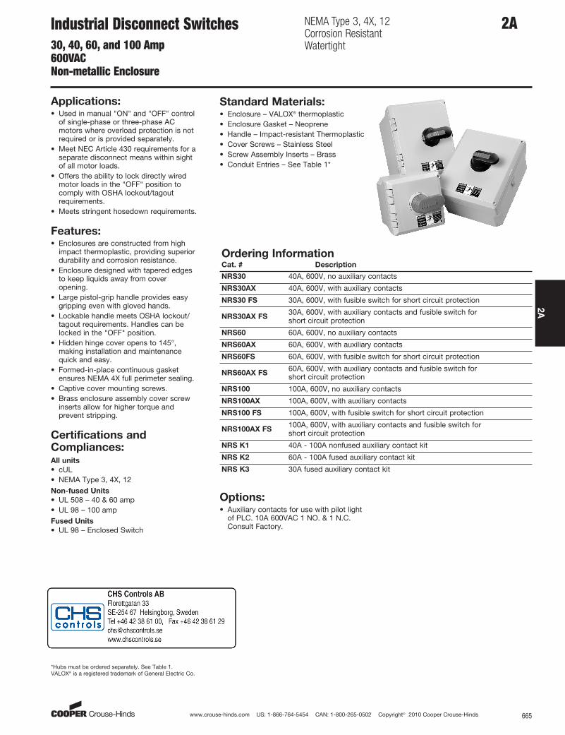
2AIndustrial Disconnect Switches30, 40, 60, and 100 Amp600VACNon-metallic Enclosure
NEMA Type 3, 4X, 12Corrosion ResistantWatertight
Applications:• Used in manual "ON" and "OFF" control
of single-phase or three-phase ACmotors where overload protection is notrequired or is provided separately.
• Meet NEC Article 430 requirements for aseparate disconnect means within sightof all motor loads.
• Offers the ability to lock directly wiredmotor loads in the "OFF" position tocomply with OSHA lockout/tagoutrequirements.
• Meets stringent hosedown requirements.
Features:• Enclosures are constructed from high
impact thermoplastic, providing superiordurability and corrosion resistance.
• Enclosure designed with tapered edgesto keep liquids away from coveropening.
• Large pistol-grip handle provides easygripping even with gloved hands.
• Lockable handle meets OSHA lockout/tagout requirements. Handles can belocked in the "OFF" position.
• Hidden hinge cover opens to 145°,making installation and maintenancequick and easy.
• Formed-in-place continuous gasketensures NEMA 4X full perimeter sealing.
• Captive cover mounting screws.• Brass enclosure assembly cover screw
inserts allow for higher torque andprevent stripping.
Certifications andCompliances:All units
• cUL• NEMA Type 3, 4X, 12Non-fused Units
• UL 508 – 40 & 60 amp• UL 98 – 100 ampFused Units
• UL 98 – Enclosed Switch
Standard Materials:• Enclosure – VALOX® thermoplastic• Enclosure Gasket – Neoprene• Handle – Impact-resistant Thermoplastic• Cover Screws – Stainless Steel• Screw Assembly Inserts – Brass• Conduit Entries – See Table 1*
Options:• Auxiliary contacts for use with pilot light
of PLC. 10A 600VAC 1 NO. & 1 N.C.Consult Factory.
Ordering InformationCat. # Description
NRS30 40A, 600V, no auxiliary contacts
NRS30AX 40A, 600V, with auxiliary contacts
NRS30 FS 30A, 600V, with fusible switch for short circuit protection
NRS30AX FS30A, 600V, with auxiliary contacts and fusible switch for short circuit protection
NRS60 60A, 600V, no auxiliary contacts
NRS60AX 60A, 600V, with auxiliary contacts
NRS60FS 60A, 600V, with fusible switch for short circuit protection
NRS60AX FS60A, 600V, with auxiliary contacts and fusible switch for short circuit protection
NRS100 100A, 600V, no auxiliary contacts
NRS100AX 100A, 600V, with auxiliary contacts
NRS100 FS 100A, 600V, with fusible switch for short circuit protection
NRS100AX FS100A, 600V, with auxiliary contacts and fusible switch for short circuit protection
NRS K1 40A - 100A nonfused auxiliary contact kit
NRS K2 60A - 100A fused auxiliary contact kit
NRS K3 30A fused auxiliary contact kit
*Hubs must be ordered separately. See Table 1.VALOX® is a registered trademark of General Electric Co.
www.crouse-hinds.com US: 1-866-764-5454 CAN: 1-800-265-0502 Copyright© 2010 Cooper Crouse-Hinds666
2A
Electrical Rating Ranges:Horsepower Ratings:
Single Phase Three Phase
Switches 120V 240V 208V 240V 480V 600V
40A Nonfused 1 5 10 10 20 2560A Nonfused 2 7.5 15 15 30 30100A Nonfused 5 15 25 30 50 5030A Fused 2 3 7.5 7.5 15 2060A Fused – – 15 15 30 50100A Fused – – 25 30 60 75
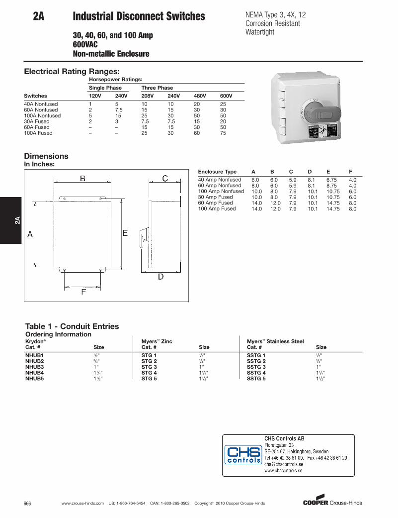
DimensionsIn Inches:
Enclosure Type A B C D E F
40 Amp Nonfused 6.0 6.0 5.9 8.1 6.75 4.060 Amp Nonfused 8.0 6.0 5.9 8.1 8.75 4.0100 Amp Nonfused 10.0 8.0 7.9 10.1 10.75 6.030 Amp Fused 10.0 8.0 7.9 10.1 10.75 6.060 Amp Fused 14.0 12.0 7.9 10.1 14.75 8.0100 Amp Fused 14.0 12.0 7.9 10.1 14.75 8.0
Table 1 - Conduit EntriesOrdering InformationKrydon® Myers™ Zinc Myers™ Stainless SteelCat. # Size Cat. # Size Cat. # Size
NHUB1 1/2" STG 1 1/2" SSTG 1 1/2"NHUB2 3/4" STG 2 3/4" SSTG 2 3/4"NHUB3 1" STG 3 1" SSTG 3 1"NHUB4 11/4" STG 4 11/4" SSTG 4 11/4"NHUB5 11/2" STG 5 11/2" SSTG 5 11/2"
2A Industrial Disconnect Switches
30, 40, 60, and 100 Amp600VACNon-metallic Enclosure
NEMA Type 3, 4X, 12Corrosion ResistantWatertight

www.crouse-hinds.com US: 1-866-764-5454 CAN: 1-800-265-0502 Copyright© 2010 Cooper Crouse-Hinds 667
2A
2AManual ContactorsAC Only, Full Voltage30A/40A/60A 600VACWithout Overload Protection
Applications:Manual Contactors are used:• For manual starting of motors up to 30
HP• In damp or wet locations
Features:Compact enclosure meets NEMA 3Rrequirements• Can be padlocked to help conform to
OSHA lockout requirements• Grounding terminal provides ground for
box and cover• Enclosed switch body does not expose
contacts• Double break butt-type silver alloy
contacts provide long life• Two 1/2", 3/4", 1" knockouts on bottom
Certifications andCompliances:• UL 508• CSA Standard: C22.2 No. 14• NEMA 3R
Standard Materials:• .060" thick steel enclosure
Standard Finishes:6810 / 7810 Series:
• Gray baked enamel finishMC Series:
• Polyester urethane
Electrical Rating Ranges:• 30A/40A/60A 600VAC, two pole, single
phase• 30A/40A/60A 600VAC, three pole,
polyphase
Ordering Information:Horsepower
Description
Amps
600V 120V 240V
480/
600V
Switch
Cat. #
Switch &
Enclosure
Cat. #
2 pole with screw terminals 30 2 5 7.5 6810U 6810W
3 pole with screw terminals 30 3 7.5 15 7810UD 7810WD
2 pole with screw & clamp terminals 40 3 5 15 MC240C MC240C-3
2 pole with box lug terminals 40 3 5 15 MC240L MC240L-3
2 pole with box lug terminals 60 3 5 15 MC260L MC260L-3
3 pole with screw & clamp terminals 40 3 7.5 15 / 20 MC340C MC340C-3
3 pole with box lug terminals 40 3 7.5 15 / 20 MC340L MC340L-3
3 pole with box lug terminals 60 3 7.5 25 / 30 MC360L MC360L-3
DimensionsIn Inches:
NEMA 3R
www.crouse-hinds.com US: 1-866-764-5454 CAN: 1-800-265-0502 Copyright© 2010 Cooper Crouse-Hinds668
2A
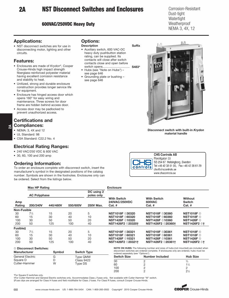
2A NST Disconnect Switches and Enclosures
600VAC/250VDC Heavy Duty
Corrosion-ResistantDust-tightWatertightWeatherproofNEMA 3, 4X, 12
Disconnect switch with built-in Krydon
material handle
Applications:• NST disconnect switches are for use in
disconnecting motor, lighting and othercircuits.
Features:• Enclosures are made of Krydon®, Cooper
Crouse-Hinds high impact strengthfiberglass-reinforced polyester materialhaving excellent corrosion resistanceand stability to heat.
• Unitized, strong and durable enclosureconstruction provides longer service lifefor equipment.
• Enclosure has hinged access door whichopens 160° for easy wiring andmaintenance. Three screws for doorframe are hidden behind access door.
• Access door may be padlocked toprevent unauthorized access.
Certifications andCompliances:• NEMA: 3, 4X and 12• UL Standard: 98• CSA Standard: C22.2 No. 4
Electrical Rating Ranges:• 240 VAC/250 VDC & 600 VAC• 30, 60, 100 and 200 amp
Options:Description Suffix
• Auxiliary switch, 600 VAC-DCheavy duty pushbutton stationrating, can be supplied. Itscontacts will close after switchcontacts close and open beforeswitch opens................................ S483*
• Hubs (see "Note on Hubs") –see page 646
• Grounding plate or bushing – see page 646
Ordering Information:To order an enclosure complete with disconnect switch, insert themanufacturer’s symbol in the designated positions of the catalognumber. Symbols are shown in the footnotes. Enclosures only canbe ordered. Select from the listings below.
Max HP Rating Enclosure
AC Polyphase
DC using 2
poles only
Amp
Rating 200/240V 440/480V 550/600V 250V Max.
With Switch
240VAC/250VDC
Cat. #
With Switch
600VAC
Cat. #
Without
Switch
Cat. #
Non-Fusible
30 71/2 15 20 5 NST1018F ➀30320 NST1018F ➀30360 NST1018F ➀60 15 30 40 10 NST1018F ➀60320 NST1018F ➀60360 NST1018F ➀100 30 50 50 20 NST1426F ➀10320 NST1426F ➀10360 NST1426F ➀200 50 125 100 40 NST1426F2 ➀20320† NST1426F2 ➀20360† NST1426F2 ➀†
Fusible‡
30 71/2 15 20 5 NST1018F ➀30321 NST1018F ➀30361 NST1018F ➀60 15 30 40 10 NST1018F ➀60321 NST1018F ➀60361 NST1018F ➀100 30 50 50 20 NST1426F ➀10321 NST1426F ➀10361 NST1426F ➀200 50 125 100 40 NST1426F2 ➀20321† NST1426F2 ➀20361† NST1426F2 ➀†
➀ Disconnect Switches:
Manufacturer Symbol Switch Type
General Electric G Type QMWSquare D D Class 9422Cutler-Hammer W Type DS
*For Square D switches only.†For Cutler-Hammer and General Electric switches only. Accommodates Class J fuses only. Not available with Cutler-Hammer "W" switch.‡Fuse clips are arranged for Class H fuses and field modifiable for Class J fuses. For Class R fuses, consult Cooper Crouse-Hinds.
NOTE ON HUBS: The following number and sizes of hubs (not mounted) are included whendisconnect switches are ordered complete. If enclosures only are ordered, hubs must beordered separately (see "Options").
Switch Size Number Included Hub Size
30 2 3/4
60 2 11/4
100 2 2200 2 21/2
www.crouse-hinds.com US: 1-866-764-5454 CAN: 1-800-265-0502 Copyright© 2010 Cooper Crouse-Hinds 669
2A
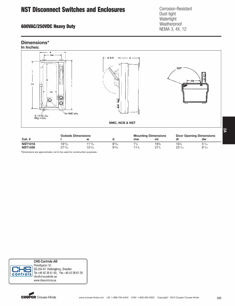
Dimensions*In Inches:
NMC, NCB & NST
Outside Dimensions Mounting Dimensions Door Opening DimensionsCat. # l w d mw ml dl dw
NST1018 1913/32 1113/32 823/32 77/8 193/8 167/8 511/16
NST1426 2713/32 1513/32 923/32 117/8 271/4 2311/16 911/16
*Dimensions are approximate, not to be used for construction purposes.
NST Disconnect Switches and Enclosures
600VAC/250VDC Heavy Duty
Corrosion-ResistantDust-tightWatertightWeatherproofNEMA 3, 4X, 12

www.crouse-hinds.com US: 1-866-764-5454 CAN: 1-800-265-0502 Copyright© 2010 Cooper Crouse-Hinds670
2A