2d & 3d semi coupled analysis...
TRANSCRIPT

Integrated Solver Optimized for the next generation 64-bit platform
Finite Element Solutions for Geotechnical Engineering
MIDASoft Inc.
Angel Francisco Martinez
Civil Engineer
MIDASoft NY office
2D & 3D Semi Coupled Analysis
Seepage-Stress-Slope
Integrated Solver Optimized for the next generation 64-bit platform
Finite Element Solutions for Geotechnical Engineering
ContentsPart 1. Overview
Part 2. 2D Slope Stability SRM
Part 3. 3D Slope Stability SRM
Part 4. 2D Dam Stability SAM
GTS NX
3
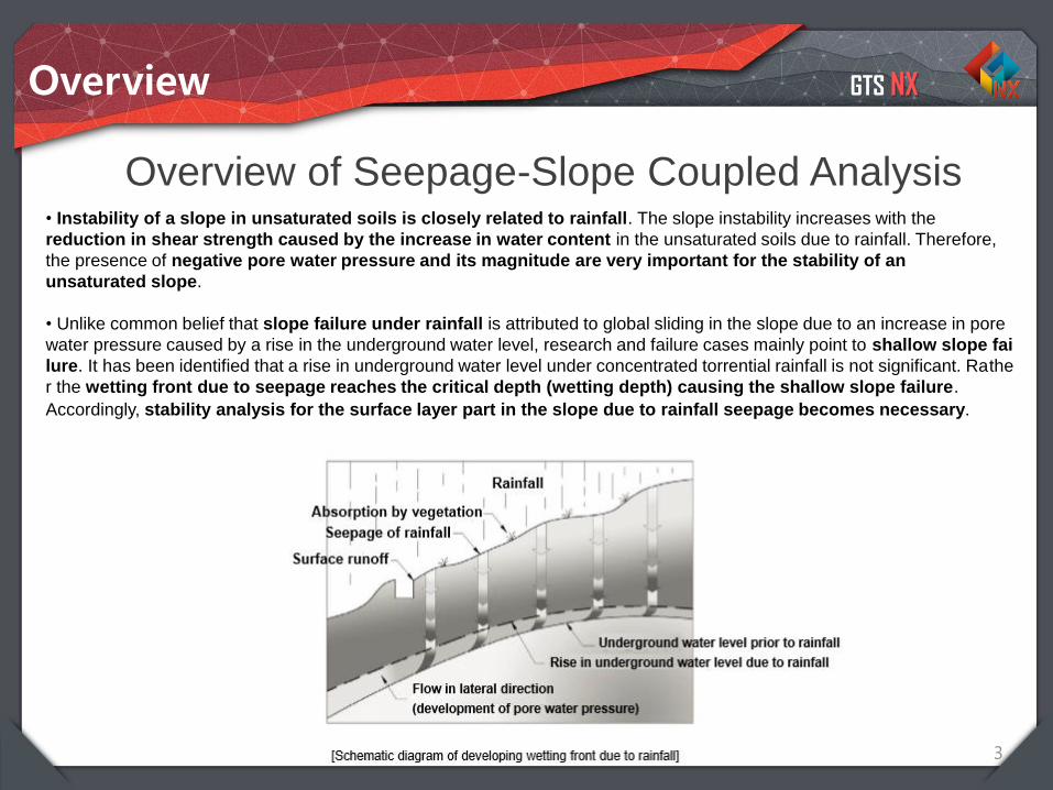
Overview of Seepage-Slope Coupled Analysis • Instability of a slope in unsaturated soils is closely related to rainfall. The slope instability increases with the
reduction in shear strength caused by the increase in water content in the unsaturated soils due to rainfall. Therefore,
the presence of negative pore water pressure and its magnitude are very important for the stability of an
unsaturated slope.
• Unlike common belief that slope failure under rainfall is attributed to global sliding in the slope due to an increase in pore
water pressure caused by a rise in the underground water level, research and failure cases mainly point to shallow slope fai
lure. It has been identified that a rise in underground water level under concentrated torrential rainfall is not significant. Rathe
r the wetting front due to seepage reaches the critical depth (wetting depth) causing the shallow slope failure.
Accordingly, stability analysis for the surface layer part in the slope due to rainfall seepage becomes necessary.
Overview
GTS NX
4
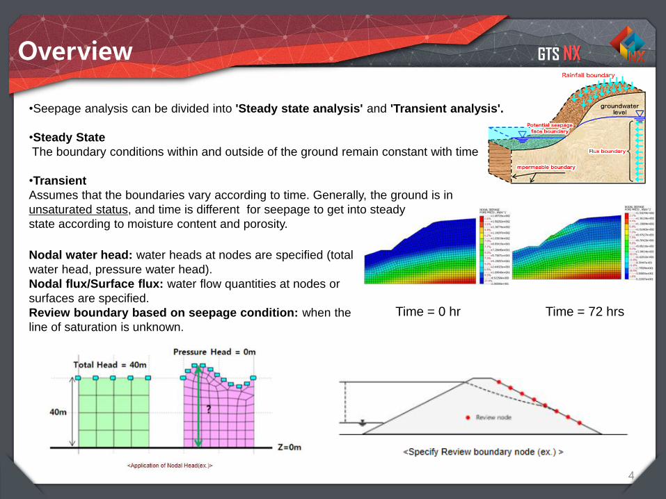
•Seepage analysis can be divided into 'Steady state analysis' and 'Transient analysis'.
•Steady State
The boundary conditions within and outside of the ground remain constant with time
•Transient
Assumes that the boundaries vary according to time. Generally, the ground is in
unsaturated status, and time is different for seepage to get into steady
state according to moisture content and porosity.
Time = 0 hr Time = 72 hrs
Nodal water head: water heads at nodes are specified (total
water head, pressure water head).
Nodal flux/Surface flux: water flow quantities at nodes or
surfaces are specified.
Review boundary based on seepage condition: when the
line of saturation is unknown.
Overview
GTS NX
5
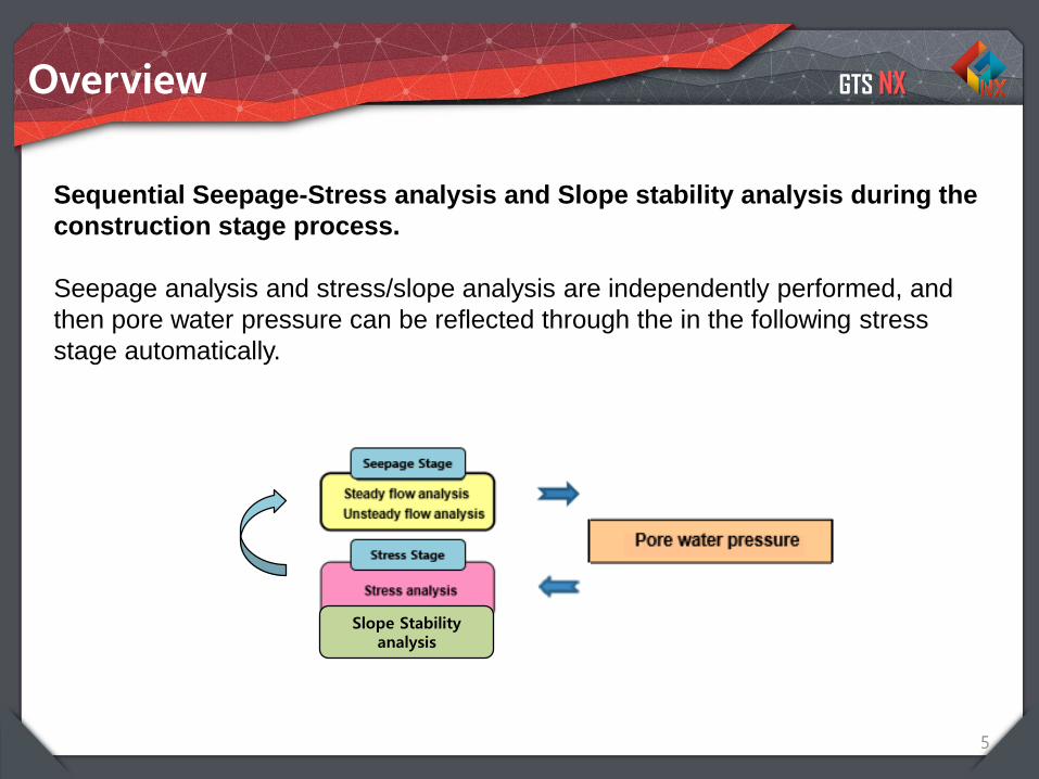
Sequential Seepage-Stress analysis and Slope stability analysis during the
construction stage process.
Seepage analysis and stress/slope analysis are independently performed, and
then pore water pressure can be reflected through the in the following stress
stage automatically.
Slope Stability analysis
Overview
GTS NX
6
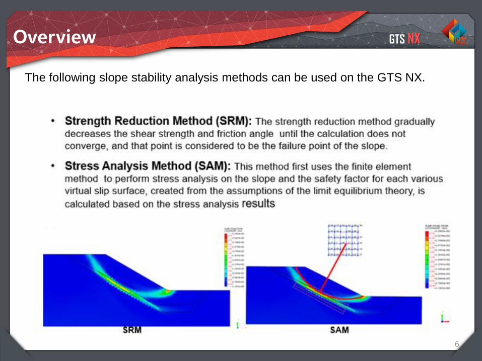
The following slope stability analysis methods can be used on the GTS NX.
Overview
Integrated Solver Optimized for the next generation 64-bit platform
Finite Element Solutions for Geotechnical Engineering
Contents
Part 1. Overview
Part 2. 2D Slope Stability SRM
Part 3. 3D Slope Stability SRM
Part 4. 2D Dam Stability SAM
GTS NX
8
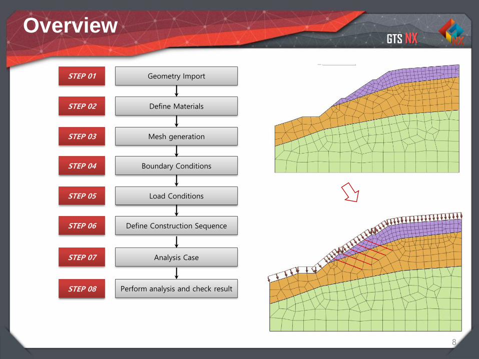
Geometry Import
Define Materials
Mesh generation
Boundary Conditions
Load Conditions
Define Construction Sequence
STEP 01
STEP 02
STEP 03
STEP 04
STEP 05
STEP 06
Analysis CaseSTEP 07
STEP 08 Perform analysis and check result
Overview
GTS NX
Overview
1-9
00 Slope Stability
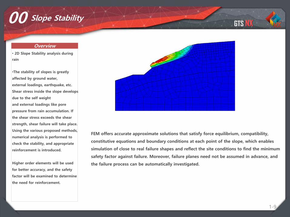
• 2D Slope Stability analysis during
rain
•The stability of slopes is greatly
affected by ground water,
external loadings, earthquake, etc.
Shear stress inside the slope develops
due to the self weight
and external loadings like pore
pressure from rain accumulation. If
the shear stress exceeds the shear
strength, shear failure will take place.
Using the various proposed methods,
numerical analysis is performed to
check the stability, and appropriate
reinforcement is introduced.
Higher order elements will be used
for better accuracy, and the safety
factor will be examined to determine
the need for reinforcement.
FEM offers accurate approximate solutions that satisfy force equilibrium, compatibility,
constitutive equations and boundary conditions at each point of the slope, which enables
simulation of close to real failure shapes and reflect the site conditions to find the minimum
safety factor against failure. Moreover, failure planes need not be assumed in advance, and
the failure process can be automatically investigated.
GTS NX
1-10
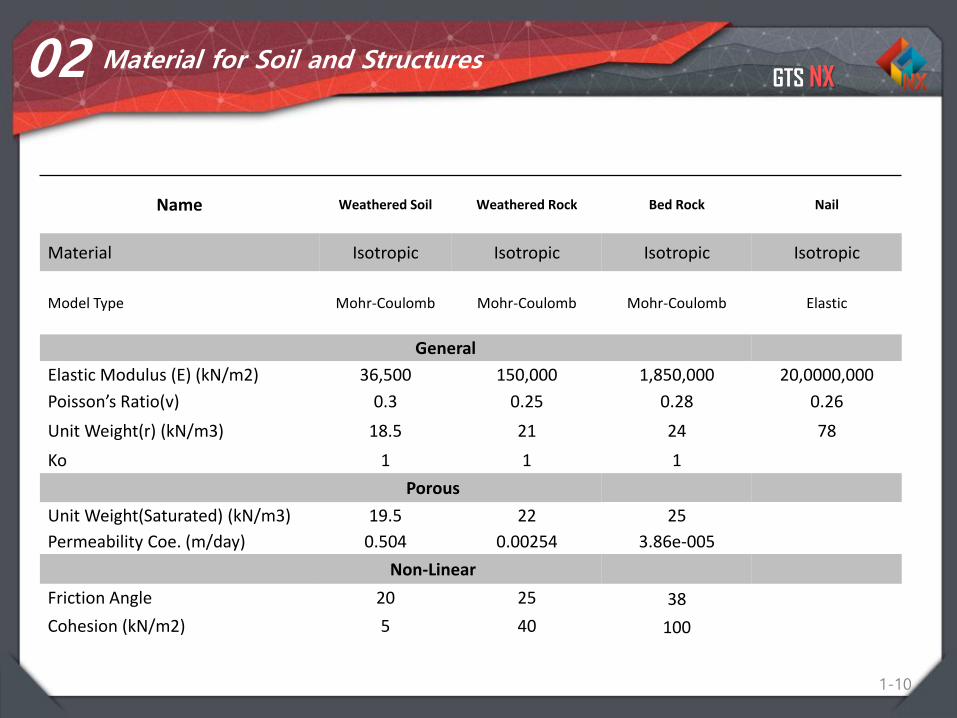
02 Material for Soil and Structures
Name Weathered Soil Weathered Rock Bed Rock Nail
Material Isotropic Isotropic Isotropic Isotropic
Model Type Mohr-Coulomb Mohr-Coulomb Mohr-Coulomb Elastic
General
Elastic Modulus (E) (kN/m2) 36,500 150,000 1,850,000 20,0000,000
Poisson’s Ratio(v) 0.3 0.25 0.28 0.26
Unit Weight(r) (kN/m3) 18.5 21 24 78
Ko 1 1 1
Porous
Unit Weight(Saturated) (kN/m3) 19.5 22 25
Permeability Coe. (m/day) 0.504 0.00254 3.86e-005
Non-Linear
Friction Angle 20 25 38
Cohesion (kN/m2) 5 40 100
GTS NX
1-11
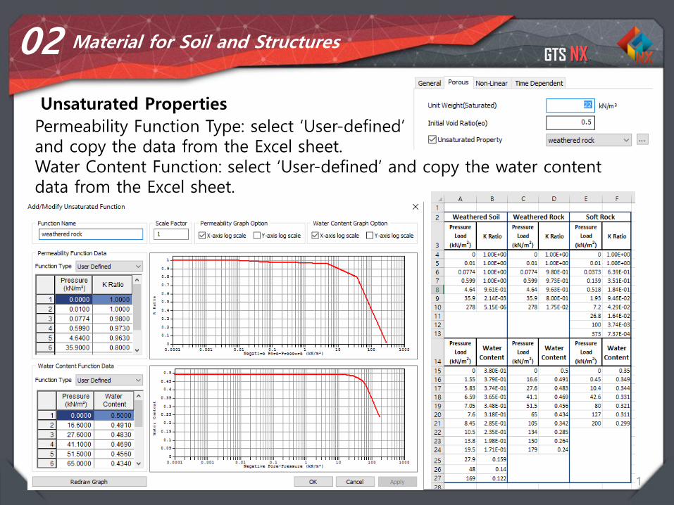
02 Material for Soil and Structures
Unsaturated Properties
Permeability Function Type: select ‘User-defined’and copy the data from the Excel sheet. Water Content Function: select ‘User-defined’ and copy the water content data from the Excel sheet.
GTS NX
1-12
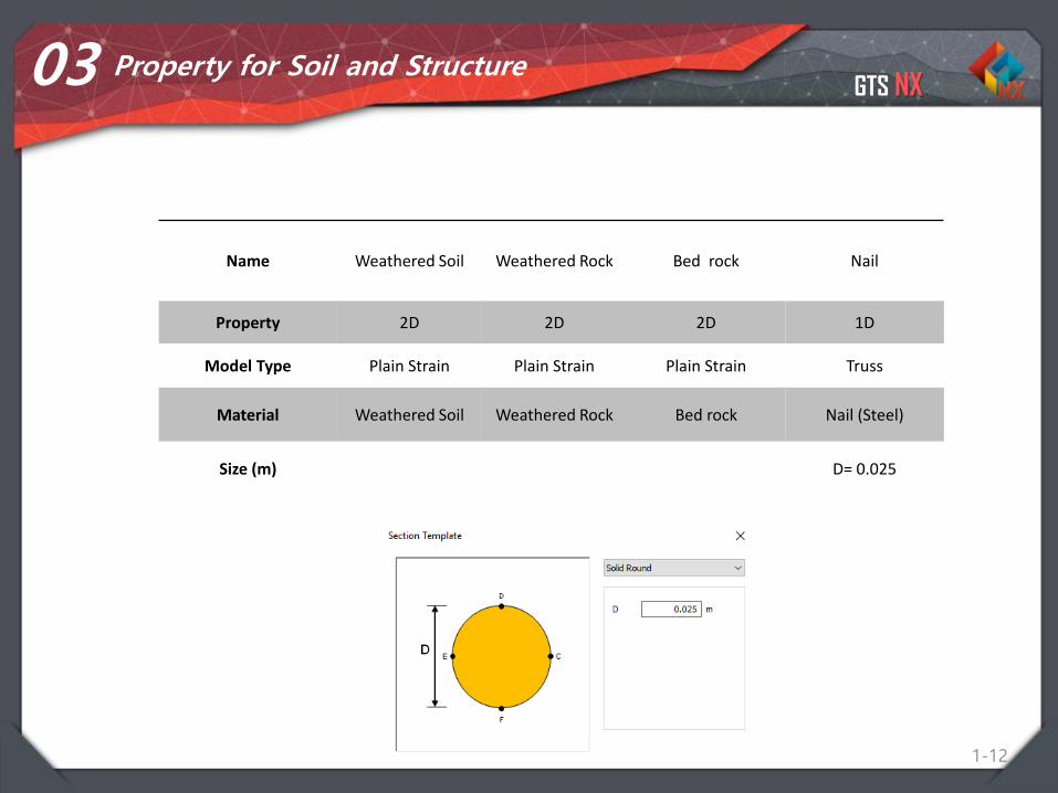
03 Property for Soil and Structure
Name Weathered Soil Weathered Rock Bed rock Nail
Property 2D 2D 2D 1D
Model Type Plain Strain Plain Strain Plain Strain Truss
Material Weathered Soil Weathered Rock Bed rock Nail (Steel)
Size (m) D= 0.025
GTS NX
1-13
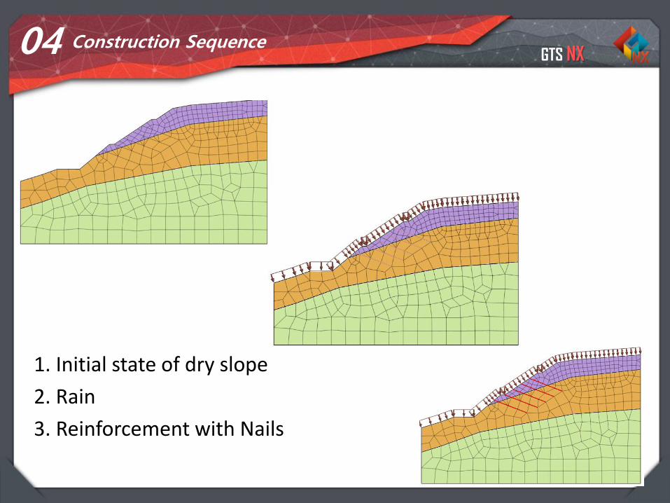
04 Construction Sequence
1. Initial state of dry slope
2. Rain
3. Reinforcement with Nails
GTS NX
Overview
1-14
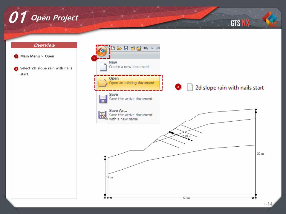
01 Open Project
11
Main Menu > Open
Select 2D slope rain with nails
start
2
2
GTS NX
Procedure
1-15
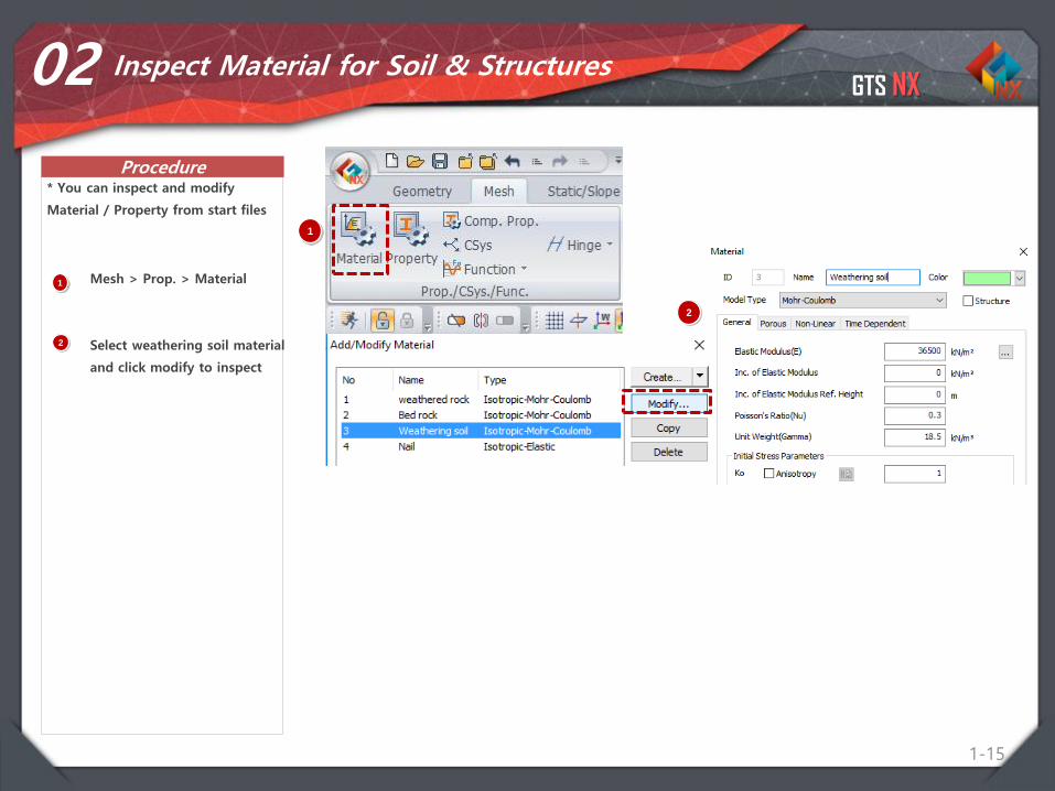
02 Inspect Material for Soil & Structures
1 Mesh > Prop. > Material
Select weathering soil material
and click modify to inspect
* You can inspect and modify
Material / Property from start files
2
1
2
GTS NX
Procedure
1-16
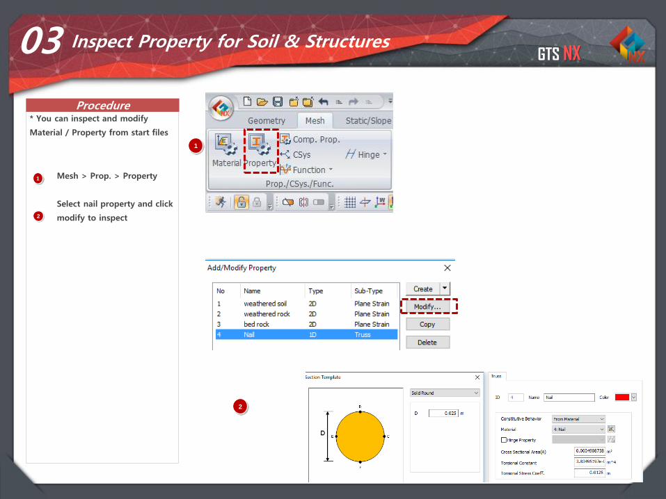
03 Inspect Property for Soil & Structures
1 Mesh > Prop. > Property
Select nail property and click
modify to inspect
* You can inspect and modify
Material / Property from start files
2
1
2
GTS NX
Procedure
1-17
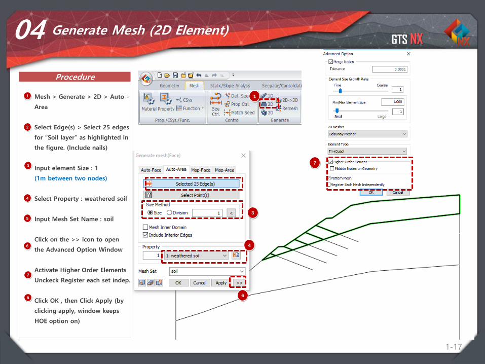
04 Generate Mesh (2D Element)
1 Mesh > Generate > 2D > Auto -
Area
Select Edge(s) > Select 25 edges
for “Soil layer” as highlighted in
the figure. (Include nails)
Input element Size : 1
(1m between two nodes)
Select Property : weathered soil
Input Mesh Set Name : soil
Click on the >> icon to open
the Advanced Option Window
Activate Higher Order Elements
Unckeck Register each set indep.
Click OK , then Click Apply (by
clicking apply, window keeps
HOE option on)
2
3
4
5
6
1
7
8
3
4
7
6
GTS NX
Procedure
1-18
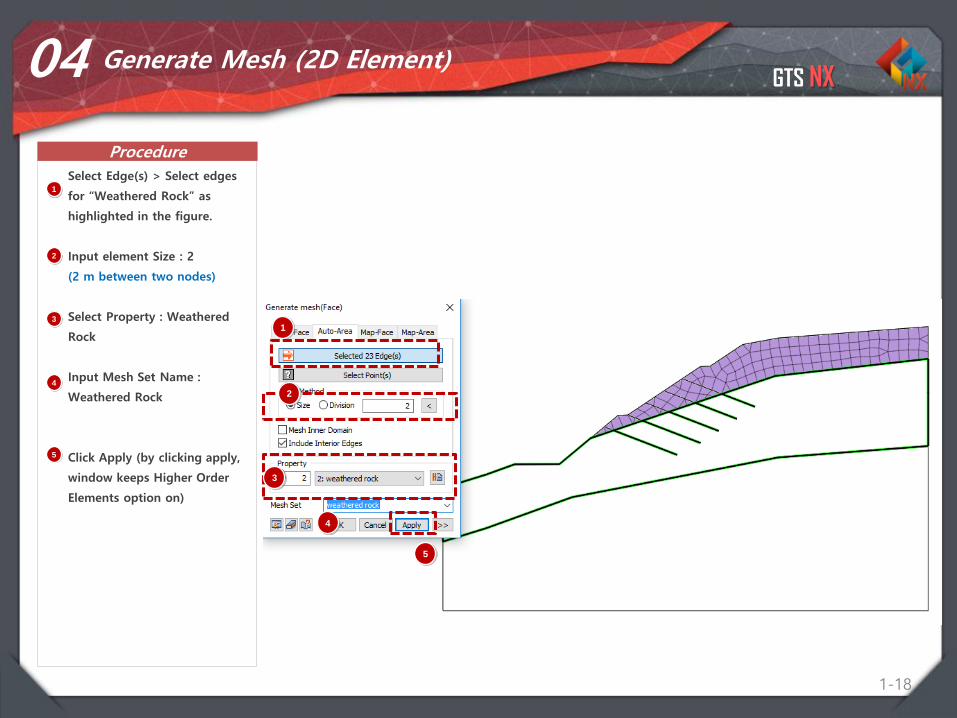
04 Generate Mesh (2D Element)
1
Select Edge(s) > Select edges
for “Weathered Rock” as
highlighted in the figure.
Input element Size : 2
(2 m between two nodes)
Select Property : Weathered
Rock
Input Mesh Set Name :
Weathered Rock
Click Apply (by clicking apply,
window keeps Higher Order
Elements option on)
1
2
3
4
5
2
3
4
5
GTS NX
Procedure
1-19
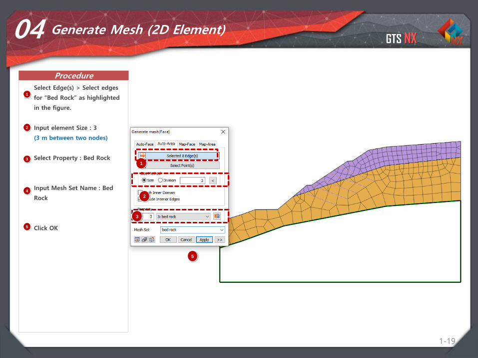
04 Generate Mesh (2D Element)
1
Select Edge(s) > Select edges
for “Bed Rock” as highlighted
in the figure.
Input element Size : 3
(3 m between two nodes)
Select Property : Bed Rock
Input Mesh Set Name : Bed
Rock
Click OK
1
2
3
4
5
2
3
5
GTS NX
Procedure
1-20
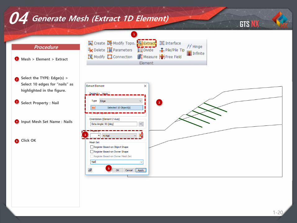
04 Generate Mesh (Extract 1D Element)
1 Mesh > Element > Extract
Select the TYPE: Edge(s) >
Select 10 edges for “nails” as
highlighted in the figure.
Select Property : Nail
Input Mesh Set Name : Nails
Click OK
1
2
3
4
5
2
3
5
GTS NX
Procedure
1-21
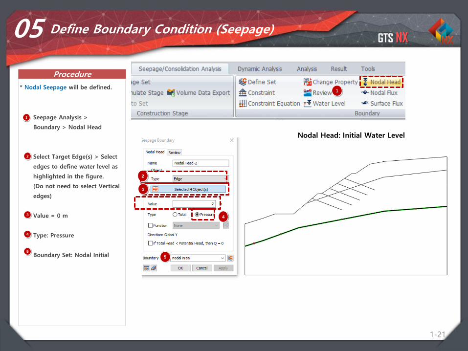
05 Define Boundary Condition (Seepage)
1 Seepage Analysis >
Boundary > Nodal Head
Select Target Edge(s) > Select
edges to define water level as
highlighted in the figure.
(Do not need to select Vertical
edges)
Value = 0 m
Type: Pressure
Boundary Set: Nodal Initial
1* Nodal Seepage will be defined.
Nodal Head: Initial Water Level
2
3
4
5
2
3
4
5
GTS NX
Procedure
1-22
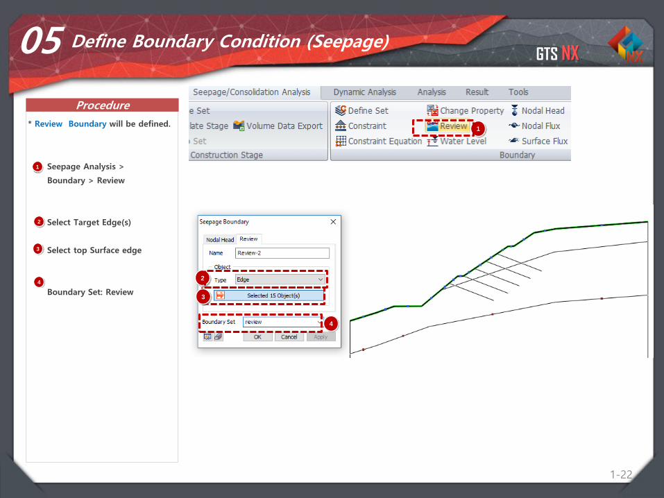
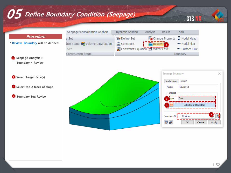
05 Define Boundary Condition (Seepage)
1 Seepage Analysis >
Boundary > Review
Select Target Edge(s)
Select top Surface edge
Boundary Set: Review
1* Review Boundary will be defined.
2
3
42
3
4
GTS NX
Procedure
1-23
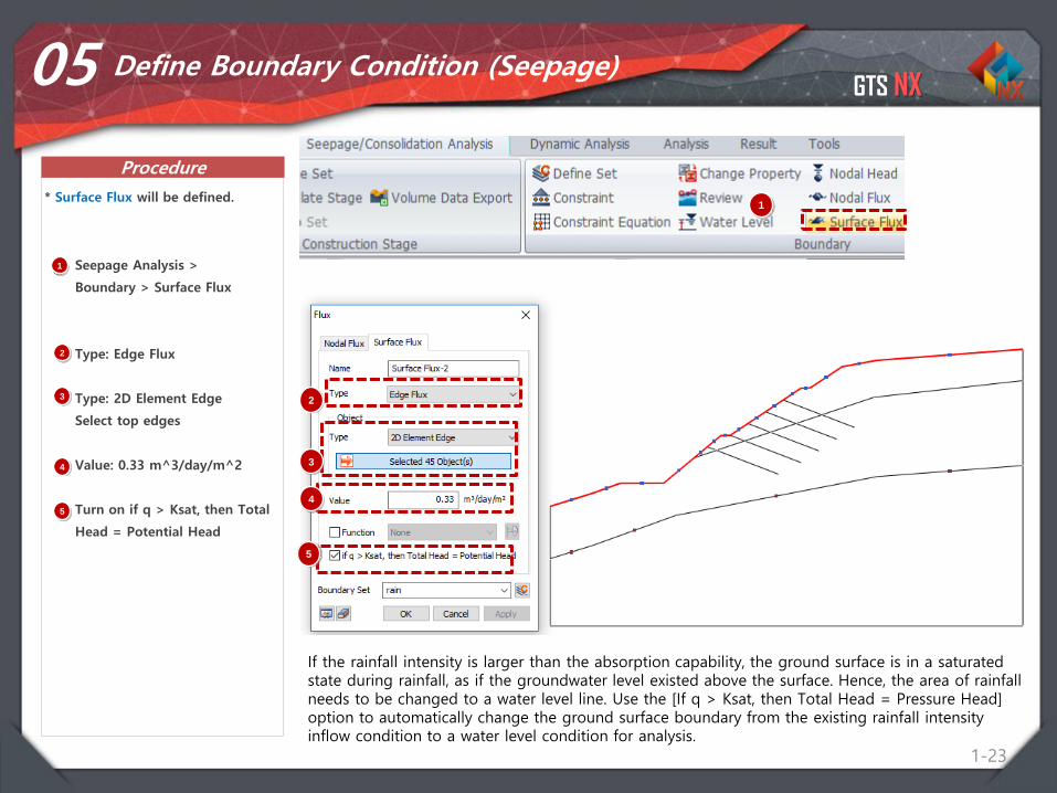
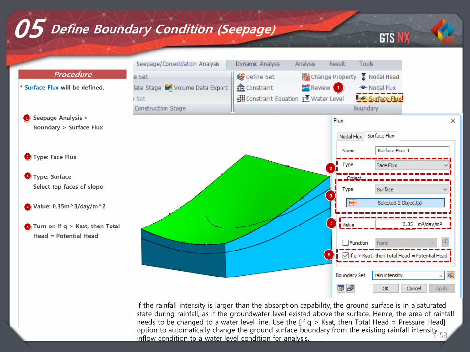
05 Define Boundary Condition (Seepage)
1 Seepage Analysis >
Boundary > Surface Flux
Type: Edge Flux
Type: 2D Element Edge
Select top edges
Value: 0.33 m^3/day/m^2
Turn on if q > Ksat, then Total
Head = Potential Head
1* Surface Flux will be defined.
2
3
4
2
3
45
5
If the rainfall intensity is larger than the absorption capability, the ground surface is in a saturated state during rainfall, as if the groundwater level existed above the surface. Hence, the area of rainfall needs to be changed to a water level line. Use the [If q > Ksat, then Total Head = Pressure Head] option to automatically change the ground surface boundary from the existing rainfall intensity inflow condition to a water level condition for analysis.
GTS NX
Procedure
1-24
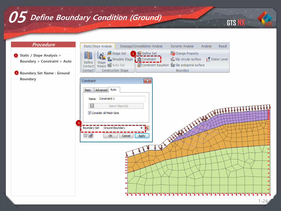
05 Define Boundary Condition (Ground)
1 Static / Slope Analysis >
Boundary > Constraint > Auto
Boundary Set Name : Ground
Boundary
1
2
2
GTS NX
Procedure
1-25
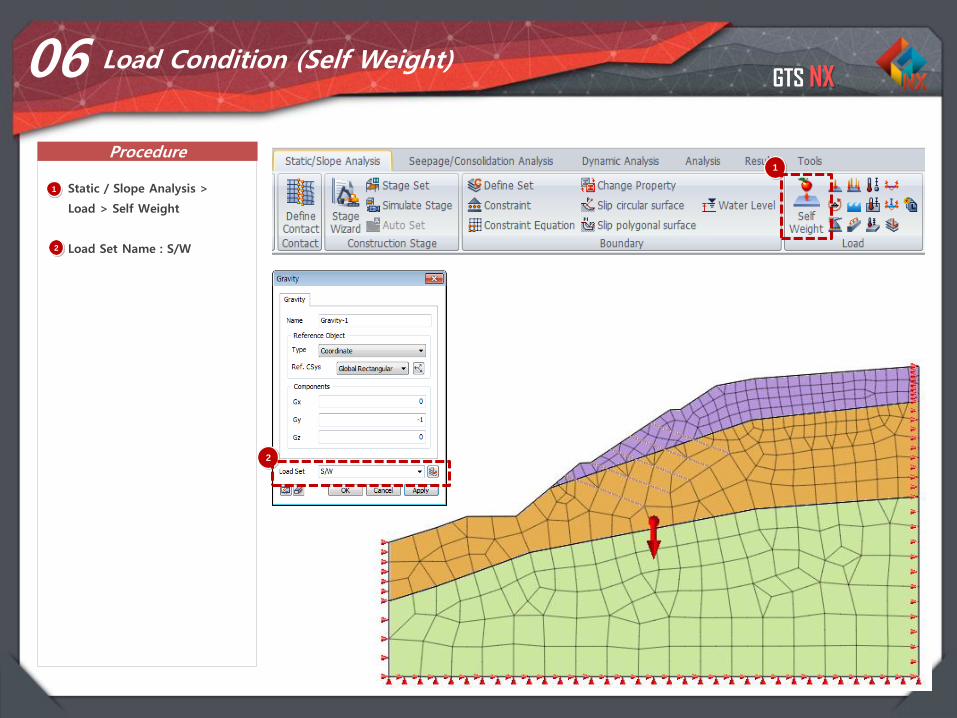
06 Load Condition (Self Weight)
1
1 Static / Slope Analysis >
Load > Self Weight
Load Set Name : S/W2
2

GTS NX
Procedure
1-26
07 Define Construction Stage (Create Stage Set)
1 Static / Slope Analysis >
Construction Stage > Stage
Set
Stage Type > Stress – Seepage
Slope
Select Add
Select Created Stage Set
Select Define CS…
* 5 Construction stage will be
defined for this project.
1
2
2
3
4
3
4
GTS NX
Procedure
1-27
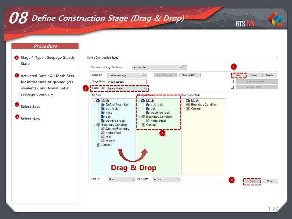
08 Define Construction Stage (Drag & Drop)
1 Stage 1 Type : Seepage Steady
State
Activated Data : All Mesh Sets
for initial state of ground (2D
elements), and Nodal Initial
seepage boundary
Select Save
Select New
2
1
2
3
4
3
4
Drag & Drop
GTS NX
Procedure
1-28
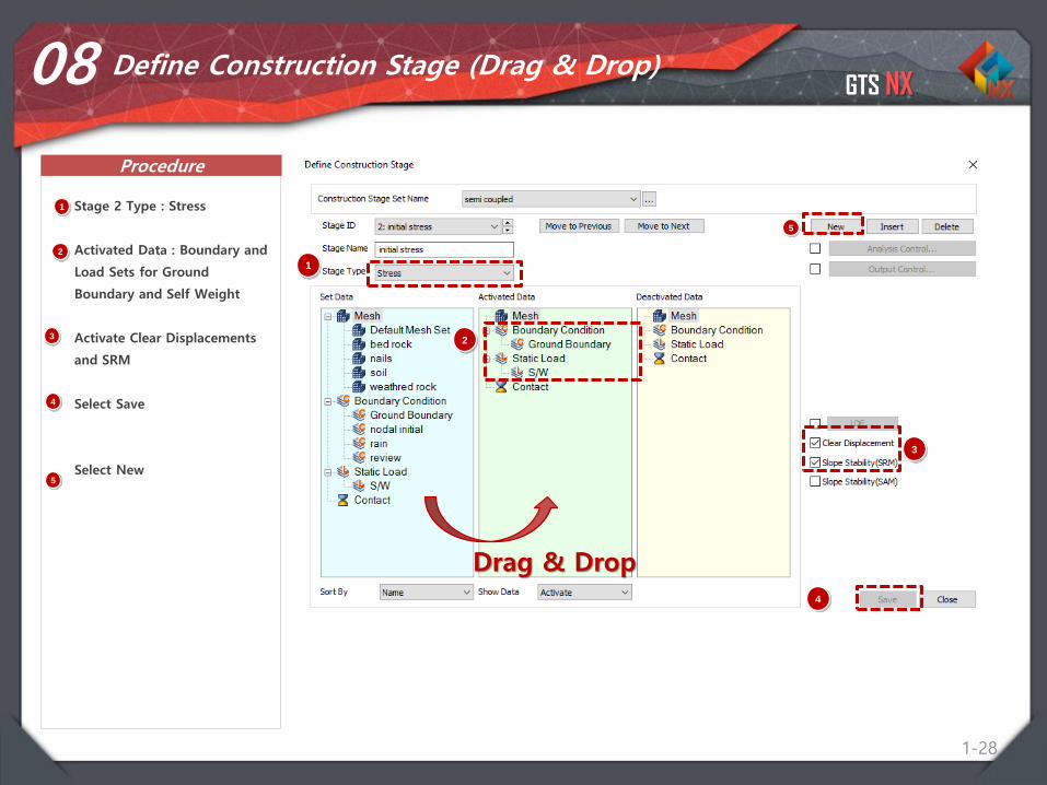
08 Define Construction Stage (Drag & Drop)
1 Stage 2 Type : Stress
Activated Data : Boundary and
Load Sets for Ground
Boundary and Self Weight
Activate Clear Displacements
and SRM
Select Save
Select New
2
1
2
3
4
Drag & Drop
3
4
5
5
GTS NX
Procedure
1-29
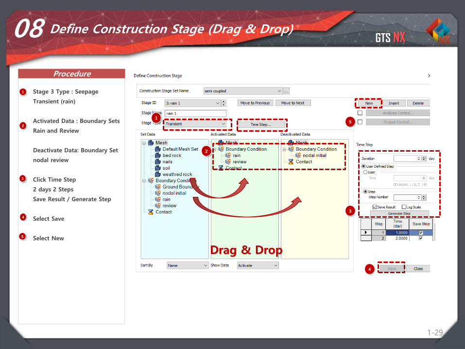
08 Define Construction Stage (Drag & Drop)
1 Stage 3 Type : Seepage
Transient (rain)
Activated Data : Boundary Sets
Rain and Review
Deactivate Data: Boundary Set
nodal review
Click Time Step
2 days 2 Steps
Save Result / Generate Step
Select Save
Select New
2
1
2
3
4
Drag & Drop
3
4
5
5
GTS NX
Procedure
1-30
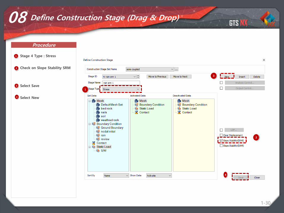
08 Define Construction Stage (Drag & Drop)
1 Stage 4 Type : Stress
Check on Slope Stability SRM
Select Save
Select New
2
1
2
3
4
3
4
GTS NX
Procedure
1-31
08 Define Construction Stage (Drag & Drop)
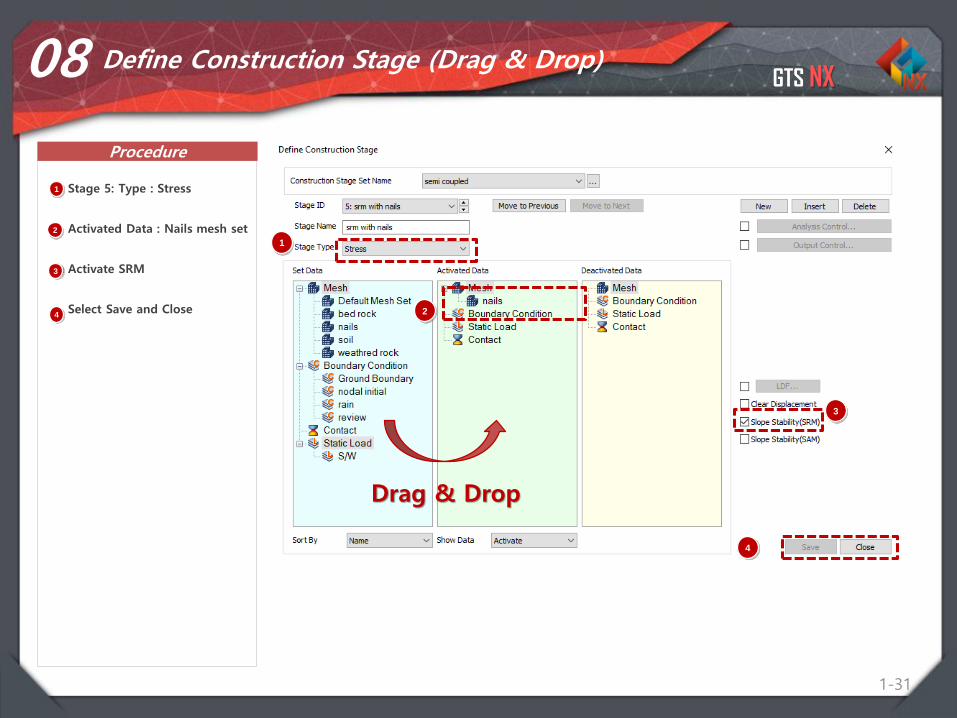
1 Stage 5: Type : Stress
Activated Data : Nails mesh set
Activate SRM
Select Save and Close 2
1
2
3
4
Drag & Drop
3
4
GTS NX
Procedure
1-32
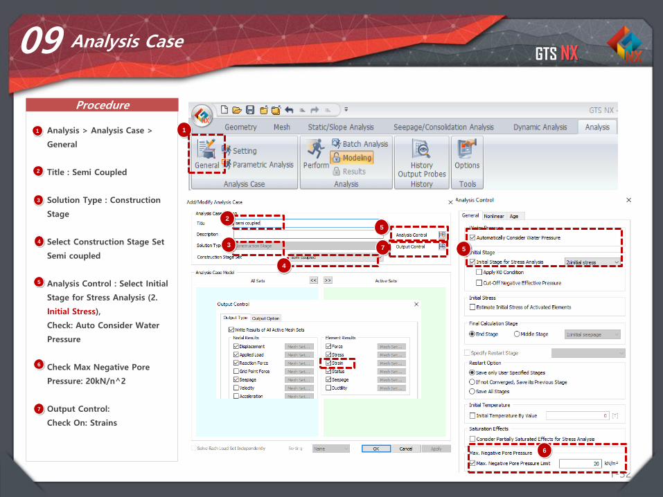
09 Analysis Case
1 Analysis > Analysis Case >
General
Title : Semi Coupled
Solution Type : Construction
Stage
Select Construction Stage Set
Semi coupled
Analysis Control : Select Initial
Stage for Stress Analysis (2.
Initial Stress),
Check: Auto Consider Water
Pressure
Check Max Negative Pore
Pressure: 20kN/n^2
Output Control:
Check On: Strains
1
2
3
4
5
2
3
4
5
5
6
7
6
7

GTS NX
Procedure
1-33
10 Perform Analysis and Check Results
1 Analysis > Analysis > Perform
Select OK
1
2
2
GTS NX
Procedure
1-34
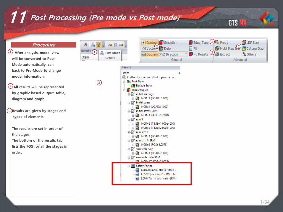
11 Post Processing (Pre mode vs Post mode)
* After analysis, model view
will be converted to Post-
Mode automatically, can
back to Pre-Mode to change
model information.
1 1
*All results will be represented
by graphic based output, table,
diagram and graph.
Results are given by stages and
types of elements.
The results are set in order of
the stages.
The bottom of the results tab
lists the FOS for all the stages in
order.
2
2
2
22
3
3
GTS NX
Procedure
1-35
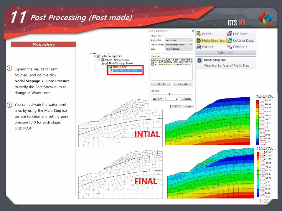
11 Post Processing (Post mode)
1 Expand the results for semi
coupled and double click
Nodal Seepage > Pore Pressure
to verify the Pore Stress dues to
change in Water Level.
You can activate the water level
lines by using the Multi Step Iso
surface function and setting pore
pressure to 0 for each stage.
Click PLOT
1
2
2
1
2
INTIAL
FINAL
GTS NX
Procedure
1-36
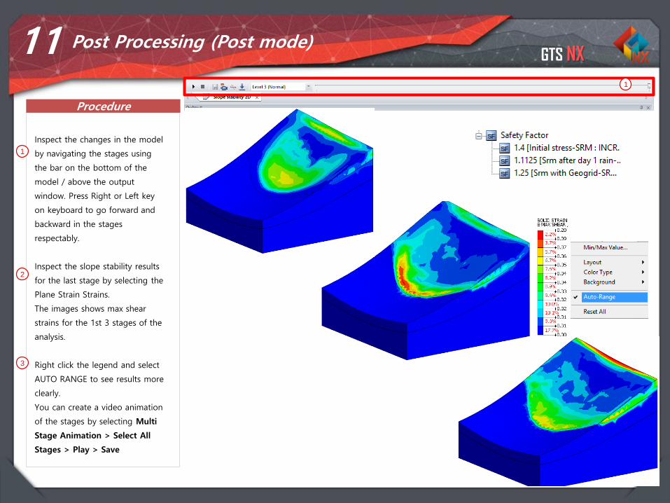
1
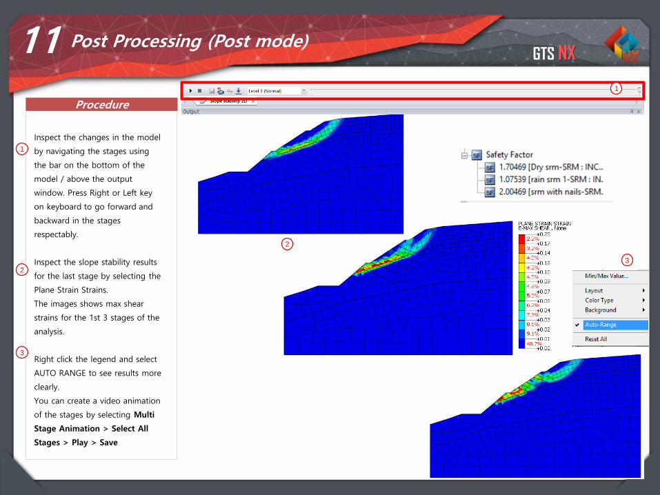
Inspect the changes in the model
by navigating the stages using
the bar on the bottom of the
model / above the output
window. Press Right or Left key
on keyboard to go forward and
backward in the stages
respectably.
Inspect the slope stability results
for the last stage by selecting the
Plane Strain Strains.
The images shows max shear
strains for the 1st 3 stages of the
analysis.
Right click the legend and select
AUTO RANGE to see results more
clearly.
You can create a video animation
of the stages by selecting Multi
Stage Animation > Select All
Stages > Play > Save
2
3
11 Post Processing (Post mode)
1
2
3
Integrated Solver Optimized for the next generation 64-bit platform
Finite Element Solutions for Geotechnical Engineering
Contents
Part 1. Overview
Part 2. 2D Slope Stability SRM
Part 3. 3D Slope Stability SRM
Part 4. 2D Dam Stability SAM
GTS NX
38
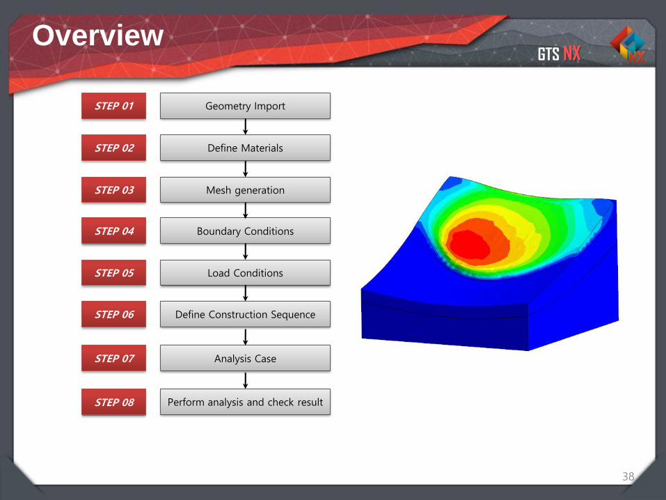
Geometry Import
Define Materials
Mesh generation
Boundary Conditions
Load Conditions
Define Construction Sequence
STEP 01
STEP 02
STEP 03
STEP 04
STEP 05
STEP 06
Analysis CaseSTEP 07
STEP 08 Perform analysis and check result
Overview
GTS NX
1-39
02 Material for Soil and Structures
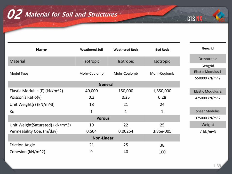
Name Weathered Soil Weathered Rock Bed Rock
Material Isotropic Isotropic Isotropic
Model Type Mohr-Coulomb Mohr-Coulomb Mohr-Coulomb
General
Elastic Modulus (E) (kN/m^2) 40,000 150,000 1,850,000
Poisson’s Ratio(v) 0.3 0.25 0.28
Unit Weight(r) (kN/m^3) 18 21 24
Ko 1 1 1
Porous
Unit Weight(Saturated) (kN/m^3) 19 22 25
Permeability Coe. (m/day) 0.504 0.00254 3.86e-005
Non-Linear
Friction Angle 21 25 38
Cohesion (kN/m^2) 9 40 100
Geogrid
Orthotropic
Geogrid
Elastic Modulus 1
550000 kN/m^2
Elastic Modulus 2
475000 kN/m^2
Shear Modulus
375000 kN/m^2
Weight
7 kN/m^3
GTS NX
1-40
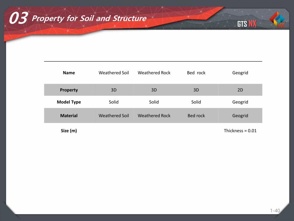
03 Property for Soil and Structure
Name Weathered Soil Weathered Rock Bed rock Geogrid
Property 3D 3D 3D 2D
Model Type Solid Solid Solid Geogrid
Material Weathered Soil Weathered Rock Bed rock Geogrid
Size (m) Thickness = 0.01
GTS NX
1-41
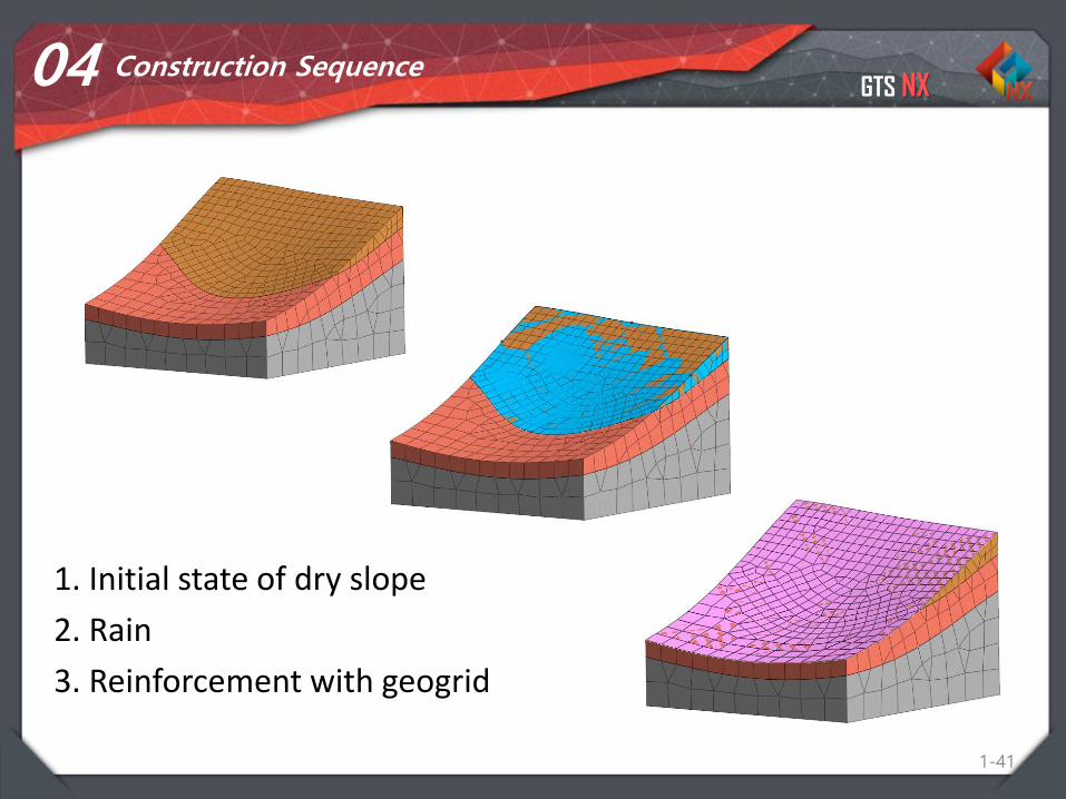
04 Construction Sequence
1. Initial state of dry slope
2. Rain
3. Reinforcement with geogrid
GTS NX
Overview
1-42
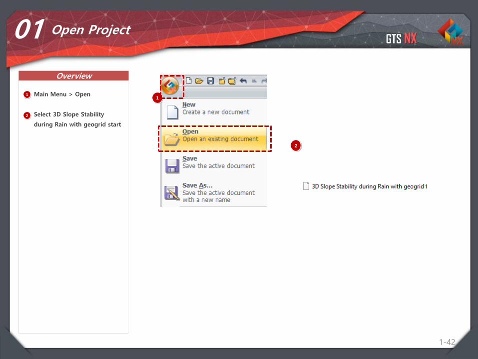
01 Open Project
11
Main Menu > Open
Select 3D Slope Stability
during Rain with geogrid start
2
2
GTS NX
Procedure
1-43
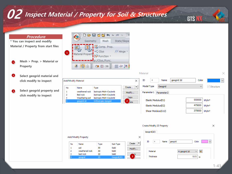
02 Inspect Material / Property for Soil & Structures
1 Mesh > Prop. > Material or
Property
Select geogrid material and
click modify to inspect
Select geogrid property and
click modify to inspect
* You can inspect and modify
Material / Property from start files
2
1
3
3
2
GTS NX
Procedure
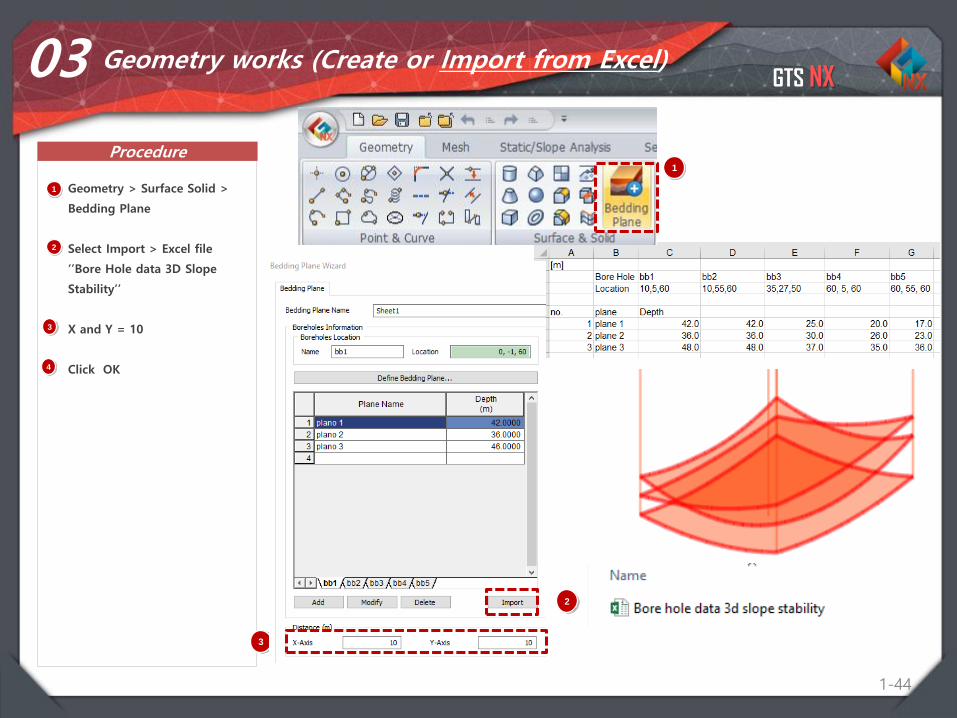
1-44
03
1
1
Geometry > Surface Solid >
Bedding Plane
Select Import > Excel file
‘’Bore Hole data 3D Slope
Stability’’
X and Y = 10
Click OK
2
2
3
3
Geometry works (Create or Import from Excel)
2
3
4
GTS NX
Procedure
1-45
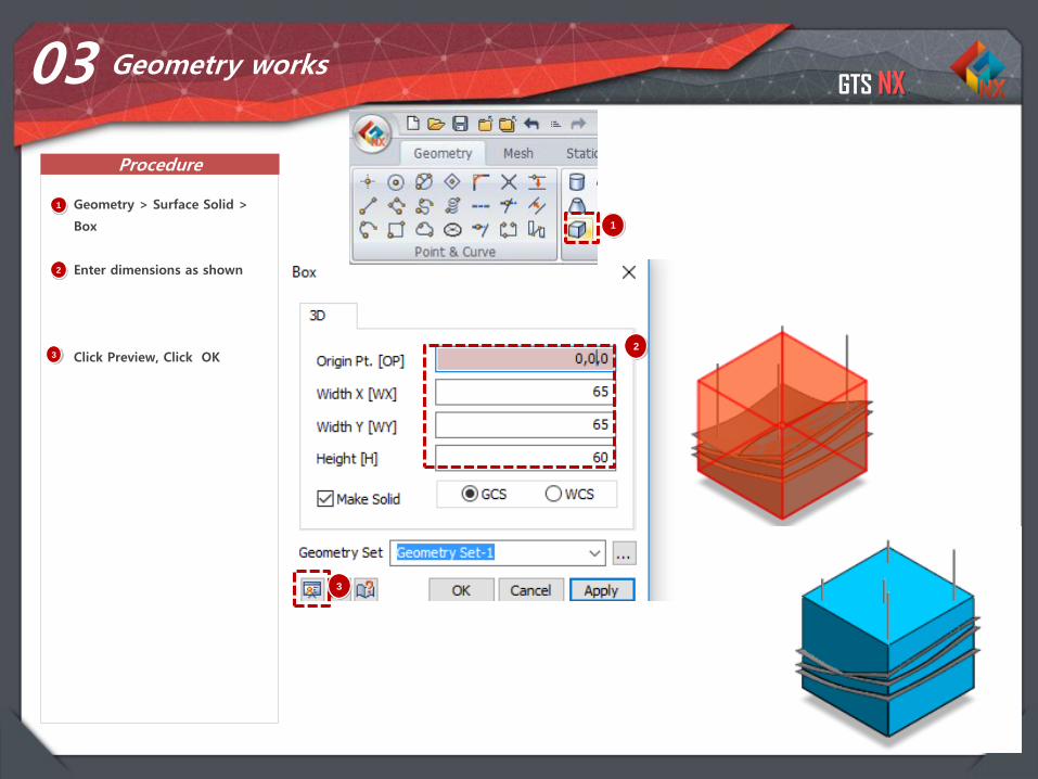
03
1
1
Geometry > Surface Solid >
Box
Enter dimensions as shown
Click Preview, Click OK
2
32
Geometry works
3
GTS NX
Procedure
1-46
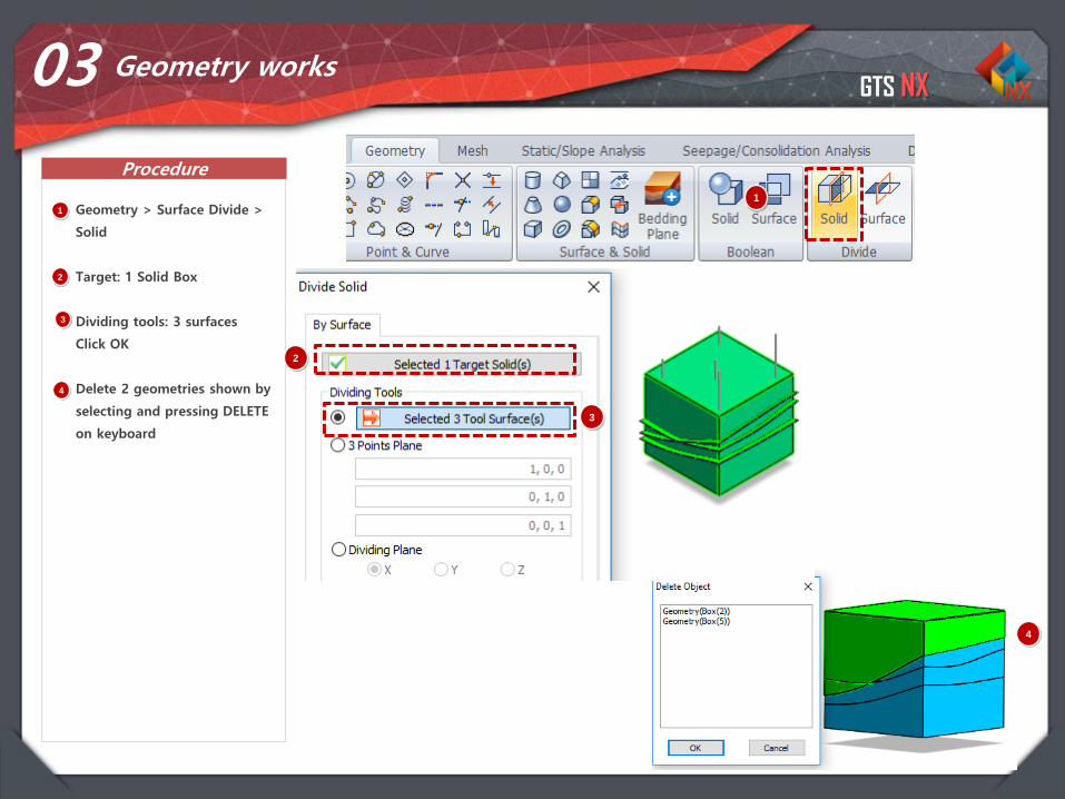
03
1
1
Geometry > Surface Divide >
Solid
Target: 1 Solid Box
Dividing tools: 3 surfaces
Click OK
Delete 2 geometries shown by
selecting and pressing DELETE
on keyboard
2
3
4
Geometry works
3
4
2
GTS NX
Procedure
1-47
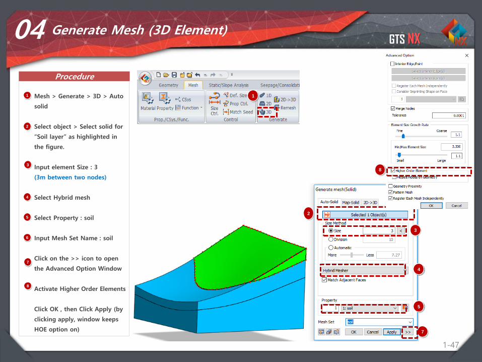
04 Generate Mesh (3D Element)
1 Mesh > Generate > 3D > Auto
solid
Select object > Select solid for
“Soil layer” as highlighted in
the figure.
Input element Size : 3
(3m between two nodes)
Select Hybrid mesh
Select Property : soil
Input Mesh Set Name : soil
Click on the >> icon to open
the Advanced Option Window
Activate Higher Order Elements
Click OK , then Click Apply (by
clicking apply, window keeps
HOE option on)
2
3
4
5
6
1
7
8
3
4
7
8
2
5
GTS NX
Procedure
1-48
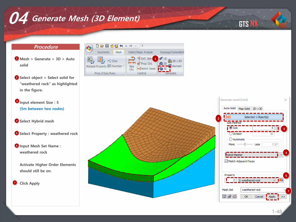
04 Generate Mesh (3D Element)
1 Mesh > Generate > 3D > Auto
solid
Select object > Select solid for
“weathered rock” as highlighted
in the figure.
Input element Size : 5
(5m between two nodes)
Select Hybrid mesh
Select Property : weathered rock
Input Mesh Set Name :
weathered rock
Activate Higher Order Elements
should still be on.
Click Apply
2
3
4
5
6
1
7
3
4
7
2
5
GTS NX
Procedure
1-49
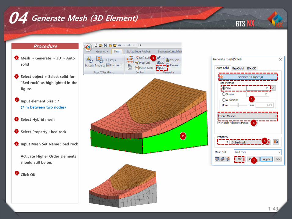
04 Generate Mesh (3D Element)
1 Mesh > Generate > 3D > Auto
solid
Select object > Select solid for
“Bed rock” as highlighted in the
figure.
Input element Size : 7
(7 m between two nodes)
Select Hybrid mesh
Select Property : bed rock
Input Mesh Set Name : bed rock
Activate Higher Order Elements
should still be on.
Click OK
2
3
4
5
6
1
7
3
4
7
2
5
GTS NX
Procedure
1-50
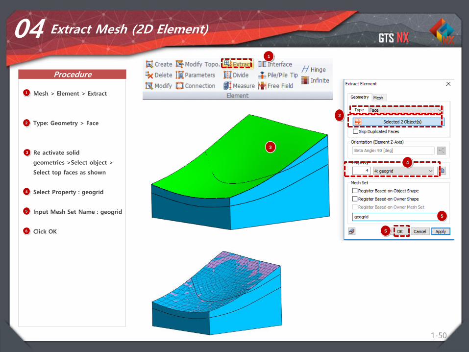
04 Extract Mesh (2D Element)
1 Mesh > Element > Extract
Type: Geometry > Face
Re activate solid
geometries >Select object >
Select top faces as shown
Select Property : geogrid
Input Mesh Set Name : geogrid
Click OK
2
3
4
5
6
1
3
4
5
2
5
GTS NX
Procedure
1-51
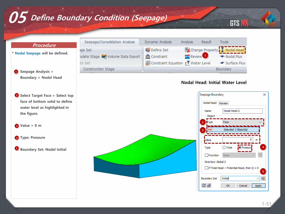
05 Define Boundary Condition (Seepage)
1 Seepage Analysis >
Boundary > Nodal Head
Select Target Face > Select top
face of bottom solid to define
water level as highlighted in
the figure.
Value = 0 m
Type: Pressure
Boundary Set: Nodal Initial
1* Nodal Seepage will be defined.
Nodal Head: Initial Water Level
2
3
4
5
2
3
4
5
GTS NX
Procedure
1-52
05 Define Boundary Condition (Seepage)
1 Seepage Analysis >
Boundary > Review
Select Target Face(s)
Select top 2 faces of slope
Boundary Set: Review
1* Review Boundary will be defined.
2
3
4
2
3
4
GTS NX
Procedure
1-53
05 Define Boundary Condition (Seepage)
1 Seepage Analysis >
Boundary > Surface Flux
Type: Face Flux
Type: Surface
Select top faces of slope
Value: 0.35m^3/day/m^2
Turn on if q > Ksat, then Total
Head = Potential Head
1* Surface Flux will be defined.
2
3
4
2
3
45
5
If the rainfall intensity is larger than the absorption capability, the ground surface is in a saturated state during rainfall, as if the groundwater level existed above the surface. Hence, the area of rainfall needs to be changed to a water level line. Use the [If q > Ksat, then Total Head = Pressure Head] option to automatically change the ground surface boundary from the existing rainfall intensity inflow condition to a water level condition for analysis.
GTS NX
Procedure
1-54
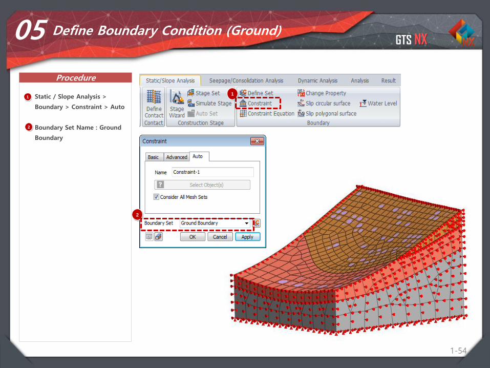
05 Define Boundary Condition (Ground)
1 Static / Slope Analysis >
Boundary > Constraint > Auto
Boundary Set Name : Ground
Boundary
1
2
2
GTS NX
Procedure
1-55
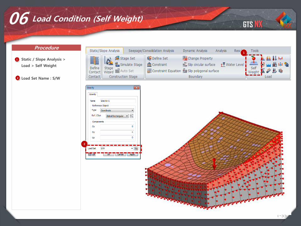
06 Load Condition (Self Weight)
1
1 Static / Slope Analysis >
Load > Self Weight
Load Set Name : S/W2
2
GTS NX
Procedure
1-56
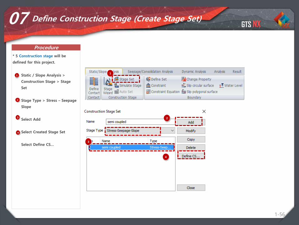
07 Define Construction Stage (Create Stage Set)
1 Static / Slope Analysis >
Construction Stage > Stage
Set
Stage Type > Stress – Seepage
Slope
Select Add
Select Created Stage Set
Select Define CS…
* 5 Construction stage will be
defined for this project.
1
2
2
3
4
3
4
GTS NX
Procedure
1-57
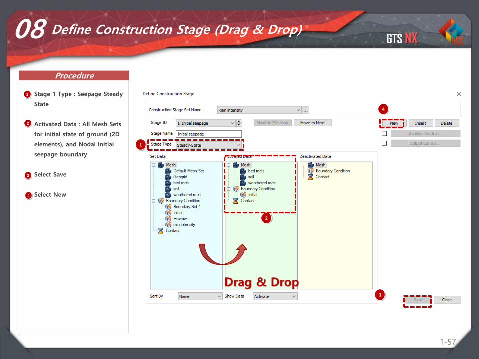
08 Define Construction Stage (Drag & Drop)
1 Stage 1 Type : Seepage Steady
State
Activated Data : All Mesh Sets
for initial state of ground (2D
elements), and Nodal Initial
seepage boundary
Select Save
Select New
2
1
2
3
4
3
4
Drag & Drop
GTS NX
Procedure
1-58
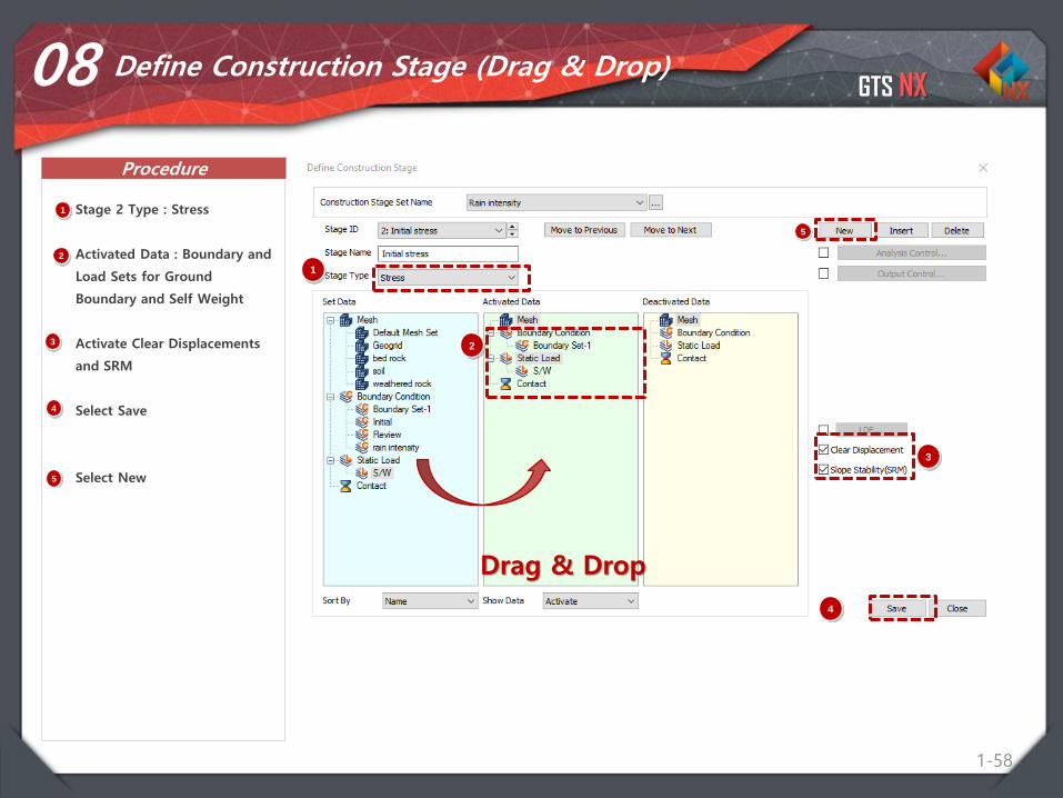
08 Define Construction Stage (Drag & Drop)
1 Stage 2 Type : Stress
Activated Data : Boundary and
Load Sets for Ground
Boundary and Self Weight
Activate Clear Displacements
and SRM
Select Save
Select New
2
1
2
3
4
Drag & Drop
3
4
5
5
GTS NX
Procedure
1-59
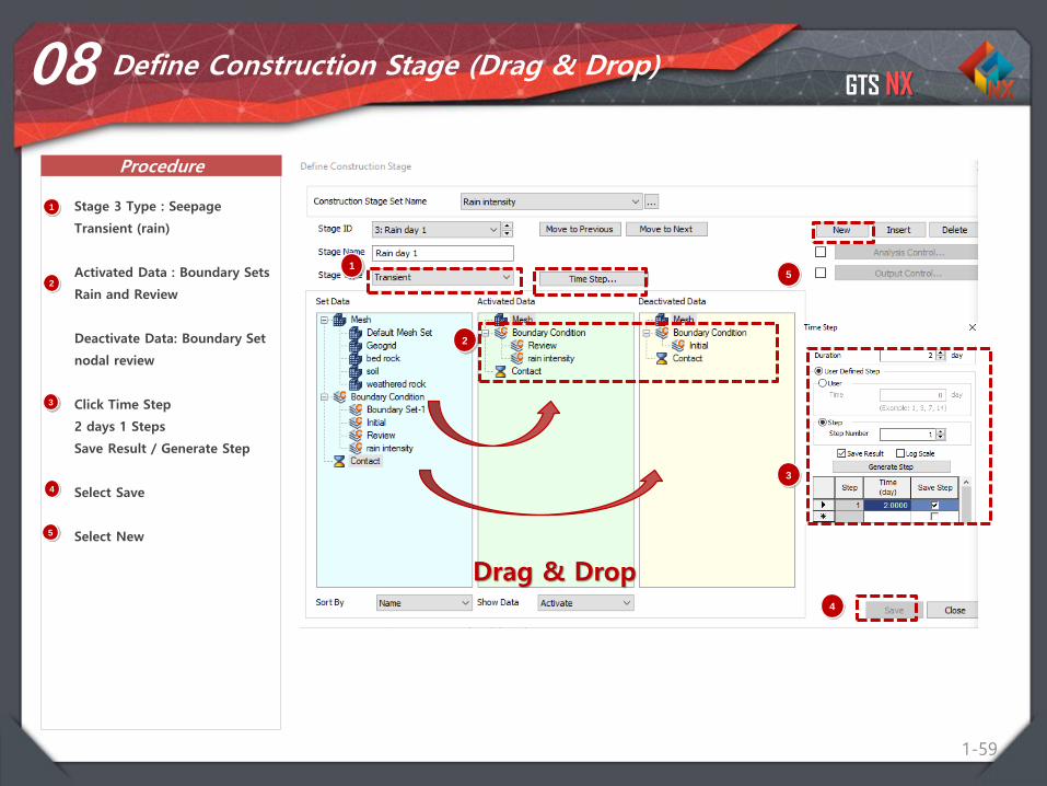
08 Define Construction Stage (Drag & Drop)
1 Stage 3 Type : Seepage
Transient (rain)
Activated Data : Boundary Sets
Rain and Review
Deactivate Data: Boundary Set
nodal review
Click Time Step
2 days 1 Steps
Save Result / Generate Step
Select Save
Select New
2
1
2
3
4
Drag & Drop
3
4
5
5
GTS NX
Procedure
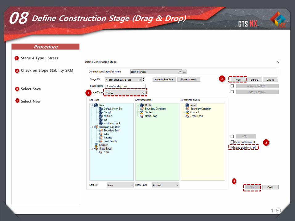
1-60
08 Define Construction Stage (Drag & Drop)
1 Stage 4 Type : Stress
Check on Slope Stability SRM
Select Save
Select New
2
1
2
3
4
3
4
GTS NX
Procedure
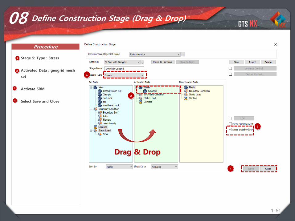
1-61
08 Define Construction Stage (Drag & Drop)
1 Stage 5: Type : Stress
Activated Data : geogrid mesh
set
Activate SRM
Select Save and Close
2
1
2
3
4
Drag & Drop
3
4

GTS NX
Procedure
1-62
09 Analysis Case
1 Analysis > Analysis Case >
General
Title : Semi Coupled 3d
Solution Type : Construction
Stage
Select Construction Stage Set
Rain intensity
Analysis Control : Select Initial
Stage for Stress Analysis (2.
Initial Stress),
Check: Auto Consider Water
Pressure
Check Max Negative Pore
Pressure: 20kN/n^2
Output Control:
Check On: Strains
1
2
3
4
5
2
3
4
5
5
6
7
6
7

GTS NX
Procedure
1-63
10 Perform Analysis and Check Results
1 Analysis > Analysis > Perform
Select OK
1
2
2
GTS NX
Procedure
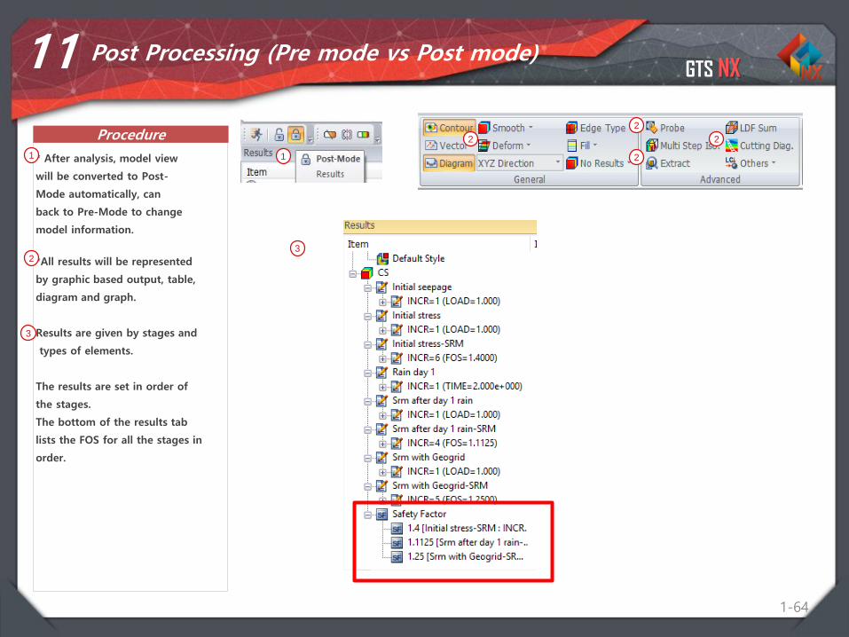
1-64
11 Post Processing (Pre mode vs Post mode)
* After analysis, model view
will be converted to Post-
Mode automatically, can
back to Pre-Mode to change
model information.
1 1
*All results will be represented
by graphic based output, table,
diagram and graph.
Results are given by stages and
types of elements.
The results are set in order of
the stages.
The bottom of the results tab
lists the FOS for all the stages in
order.
2
2
2
22
3
3
GTS NX
Procedure
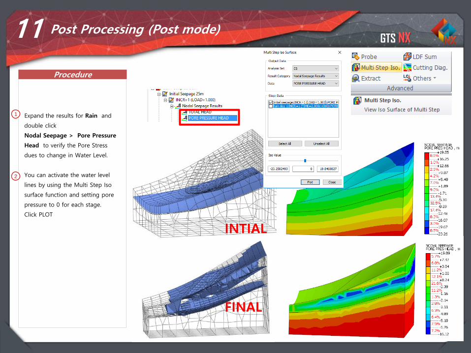
1-65
11 Post Processing (Post mode)
1 Expand the results for Rain and
double click
Nodal Seepage > Pore Pressure
Head to verify the Pore Stress
dues to change in Water Level.
You can activate the water level
lines by using the Multi Step Iso
surface function and setting pore
pressure to 0 for each stage.
Click PLOT
2
22
INTIAL
FINAL
GTS NX
Procedure
1-66
1
Inspect the changes in the model
by navigating the stages using
the bar on the bottom of the
model / above the output
window. Press Right or Left key
on keyboard to go forward and
backward in the stages
respectably.
Inspect the slope stability results
for the last stage by selecting the
Plane Strain Strains.
The images shows max shear
strains for the 1st 3 stages of the
analysis.
Right click the legend and select
AUTO RANGE to see results more
clearly.
You can create a video animation
of the stages by selecting Multi
Stage Animation > Select All
Stages > Play > Save
2
3
11 Post Processing (Post mode)
1
2
3
Integrated Solver Optimized for the next generation 64-bit platform
Finite Element Solutions for Geotechnical Engineering
Contents
Part 1. Overview
Part 2. 2D Slope Stability SRM
Part 3. 3D Slope Stability SRM
Part 4. 2D Dam Stability SAM
GTS NX
68
Geometry Import
Define Materials
Mesh generation
Boundary Conditions
Load Conditions
Define Construction Sequence
STEP 01
STEP 02
STEP 03
STEP 04
STEP 05
STEP 06
Analysis CaseSTEP 07
STEP 08 Perform analysis and check result
Overview
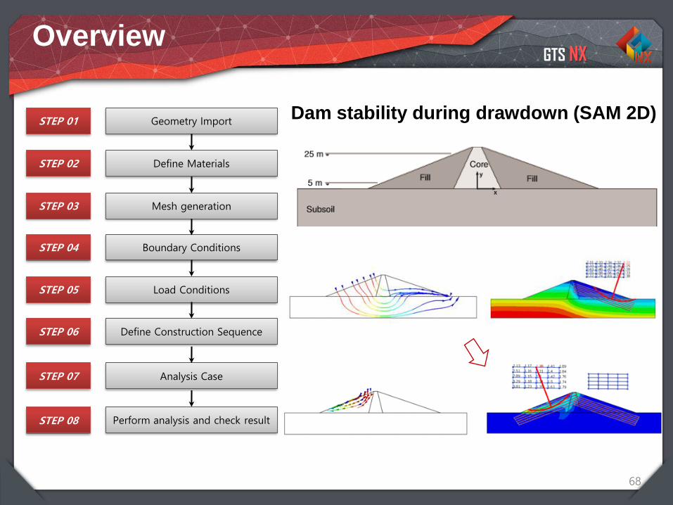
Dam stability during drawdown (SAM 2D)
GTS NX
1-69
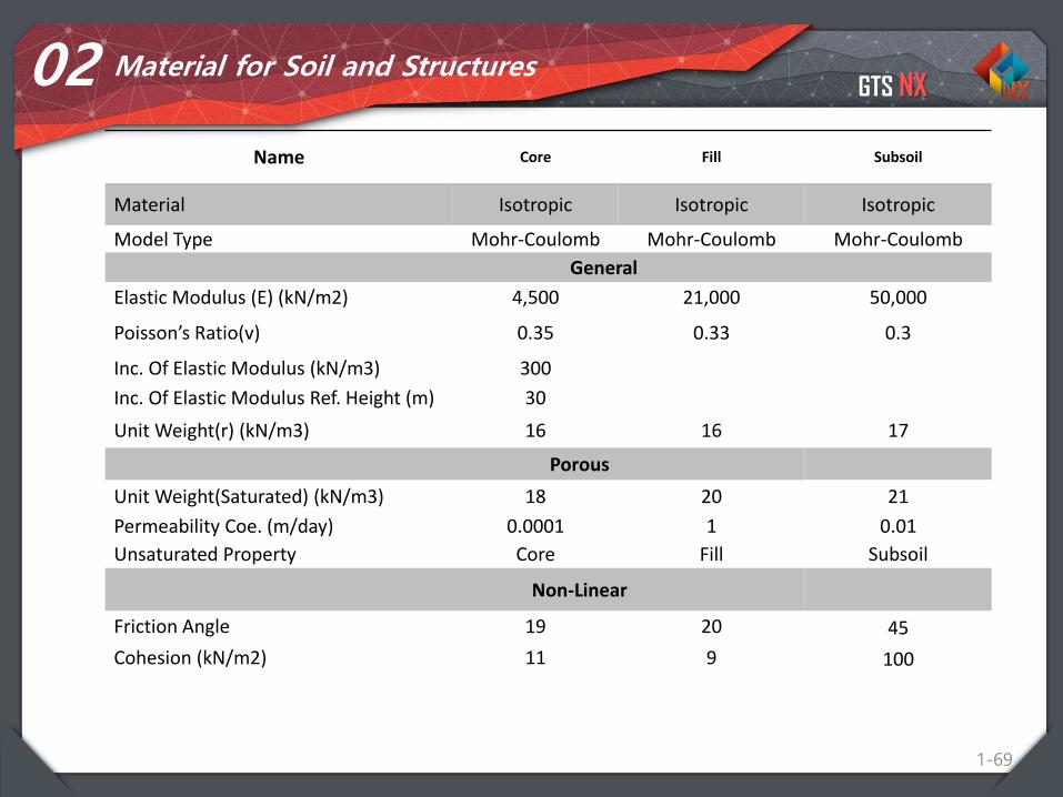
02 Material for Soil and Structures
Name Core Fill Subsoil
Material Isotropic Isotropic Isotropic
Model Type Mohr-Coulomb Mohr-Coulomb Mohr-Coulomb
General
Elastic Modulus (E) (kN/m2) 4,500 21,000 50,000
Poisson’s Ratio(v) 0.35 0.33 0.3
Inc. Of Elastic Modulus (kN/m3) 300
Inc. Of Elastic Modulus Ref. Height (m) 30
Unit Weight(r) (kN/m3) 16 16 17
Porous
Unit Weight(Saturated) (kN/m3) 18 20 21
Permeability Coe. (m/day) 0.0001 1 0.01
Unsaturated Property Core Fill Subsoil
Non-Linear
Friction Angle 19 20 45
Cohesion (kN/m2) 11 9 100
GTS NX
1-70
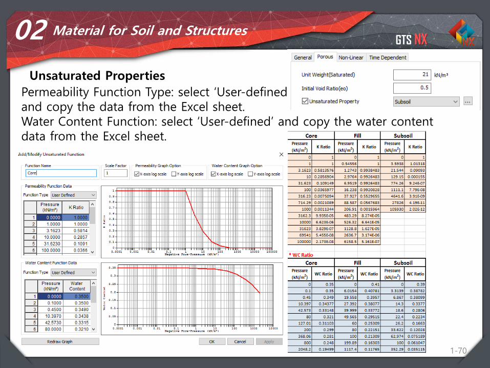
02 Material for Soil and Structures
Unsaturated Properties
Permeability Function Type: select ‘User-defined’and copy the data from the Excel sheet. Water Content Function: select ‘User-defined’ and copy the water content data from the Excel sheet.
GTS NX
1-71
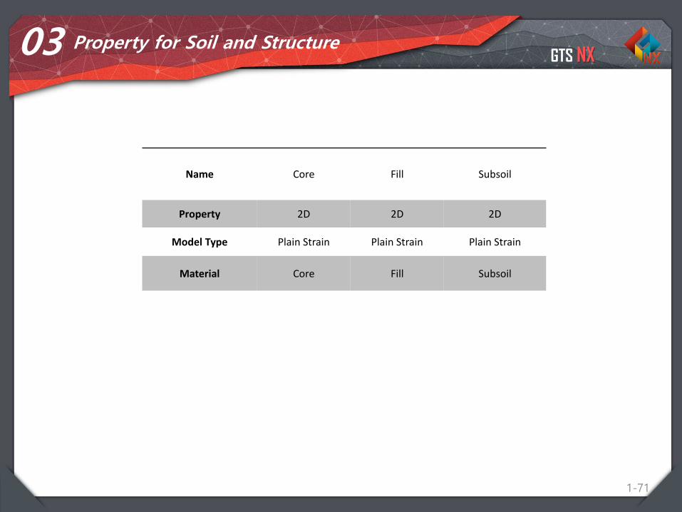
03 Property for Soil and Structure
Name Core Fill Subsoil
Property 2D 2D 2D
Model Type Plain Strain Plain Strain Plain Strain
Material Core Fill Subsoil
GTS NX
1-72
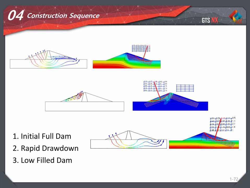
04 Construction Sequence
1. Initial Full Dam
2. Rapid Drawdown
3. Low Filled Dam
GTS NX
Procedure
73
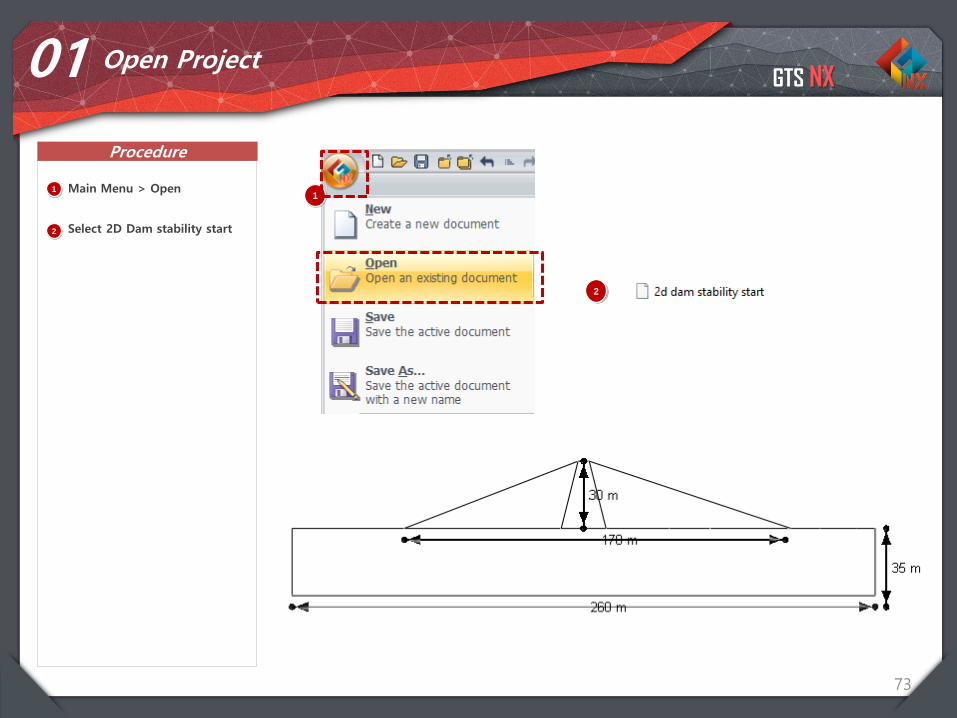
01 Open Project
11
Main Menu > Open
Select 2D Dam stability start
2
2
GTS NX
Procedure
74
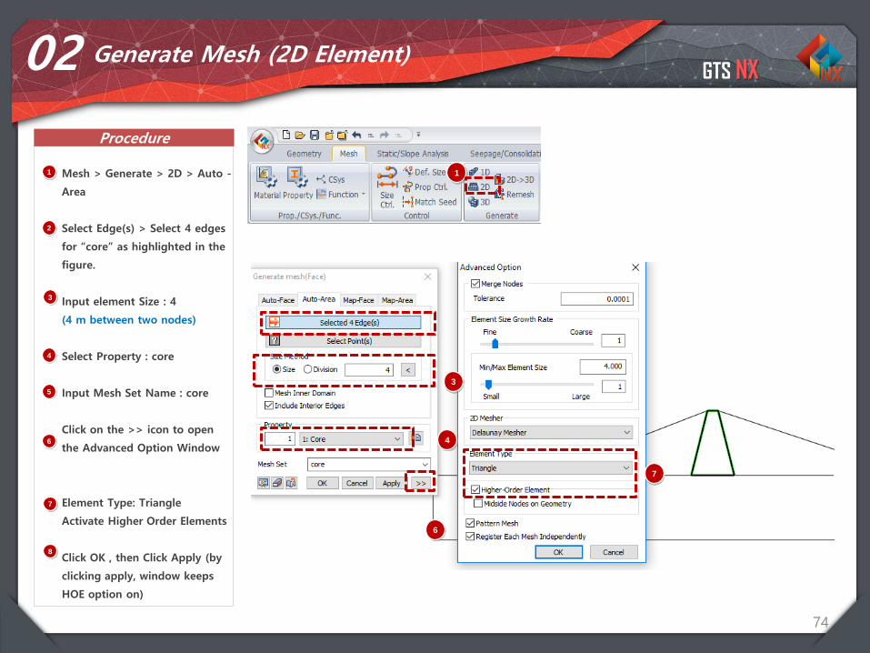
02 Generate Mesh (2D Element)
1 Mesh > Generate > 2D > Auto -
Area
Select Edge(s) > Select 4 edges
for “core” as highlighted in the
figure.
Input element Size : 4
(4 m between two nodes)
Select Property : core
Input Mesh Set Name : core
Click on the >> icon to open
the Advanced Option Window
Element Type: Triangle
Activate Higher Order Elements
Click OK , then Click Apply (by
clicking apply, window keeps
HOE option on)
2
3
4
5
6
1
7
8
3
4
7
6
GTS NX
Procedure
75
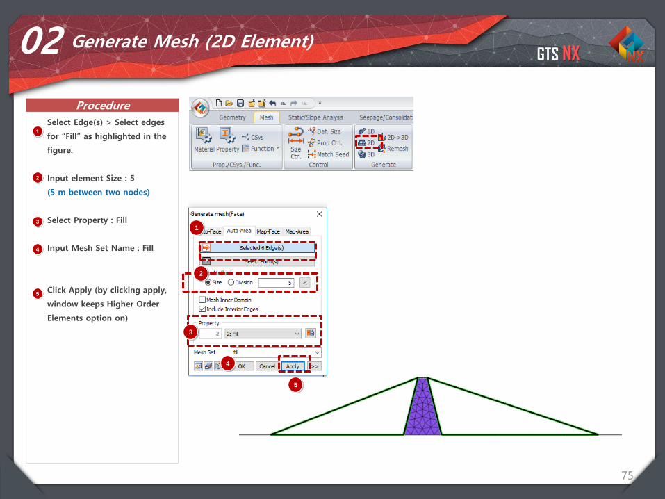
02 Generate Mesh (2D Element)
1
Select Edge(s) > Select edges
for “Fill” as highlighted in the
figure.
Input element Size : 5
(5 m between two nodes)
Select Property : Fill
Input Mesh Set Name : Fill
Click Apply (by clicking apply,
window keeps Higher Order
Elements option on)
1
2
3
4
5
2
3
4
5
GTS NX
Procedure
76
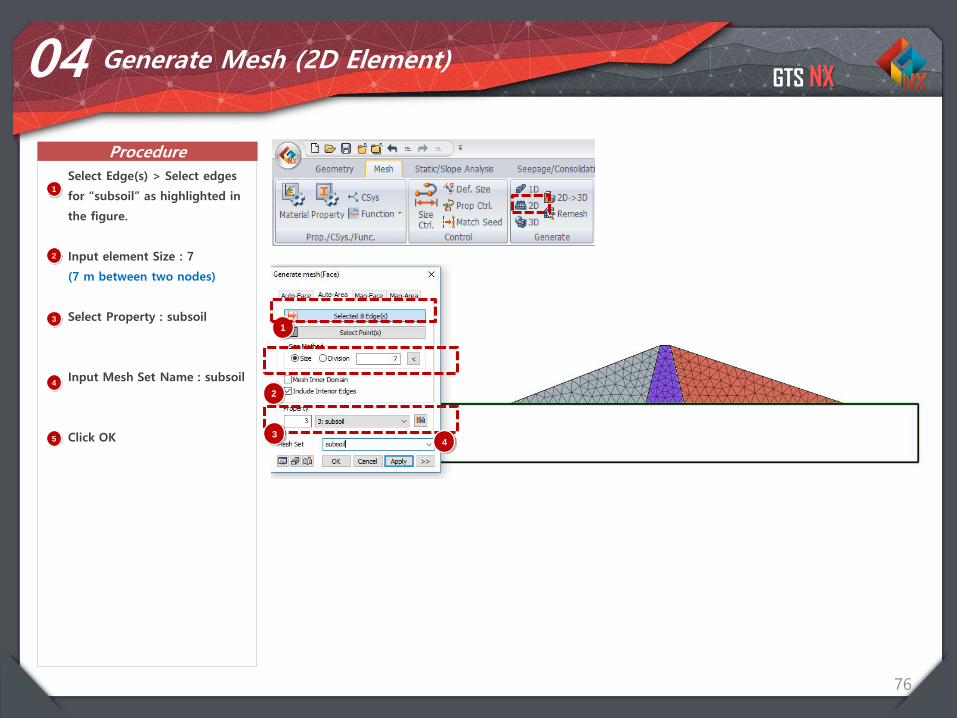
04 Generate Mesh (2D Element)
1
Select Edge(s) > Select edges
for “subsoil” as highlighted in
the figure.
Input element Size : 7
(7 m between two nodes)
Select Property : subsoil
Input Mesh Set Name : subsoil
Click OK
1
2
3
4
5
2
34
GTS NX
Procedure
77
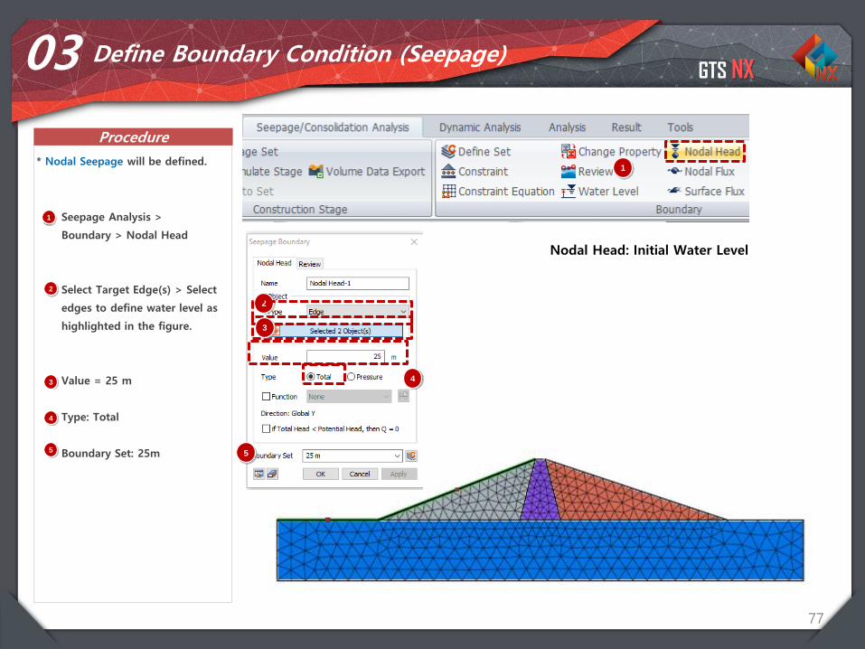
03 Define Boundary Condition (Seepage)
1 Seepage Analysis >
Boundary > Nodal Head
Select Target Edge(s) > Select
edges to define water level as
highlighted in the figure.
Value = 25 m
Type: Total
Boundary Set: 25m
1* Nodal Seepage will be defined.
Nodal Head: Initial Water Level
2
3
4
5
2
3
4
5
GTS NX
Procedure
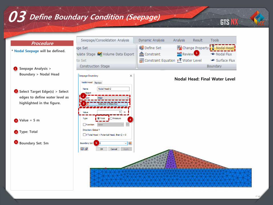
78
03 Define Boundary Condition (Seepage)
1 Seepage Analysis >
Boundary > Nodal Head
Select Target Edge(s) > Select
edges to define water level as
highlighted in the figure.
Value = 5 m
Type: Total
Boundary Set: 5m
1* Nodal Seepage will be defined.
Nodal Head: Final Water Level
2
3
4
5
2
3
4
5
GTS NX
Procedure
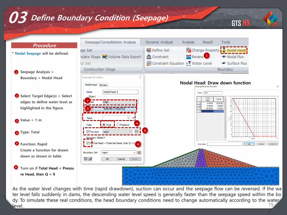
79
03 Define Boundary Condition (Seepage)
1 Seepage Analysis >
Boundary > Nodal Head
Select Target Edge(s) > Select
edges to define water level as
highlighted in the figure.
Value = 1 m
Type: Total
Function: Rapid
Create a function for drawn
down as shown in table
Turn on if Total Head < Pressu
re Head, then Q = 0
1* Nodal Seepage will be defined.
Nodal Head: Draw down function
2
3
4
5
2
3
4
5
6
6
As the water level changes with time (rapid drawdown), suction can occur and the seepage flow can be reversed. If the water level falls suddenly in dams, the descending water level speed is generally faster than the seepage speed within the body. To simulate these real conditions, the head boundary conditions need to change automatically according to the water level.
GTS NX
Procedure
80
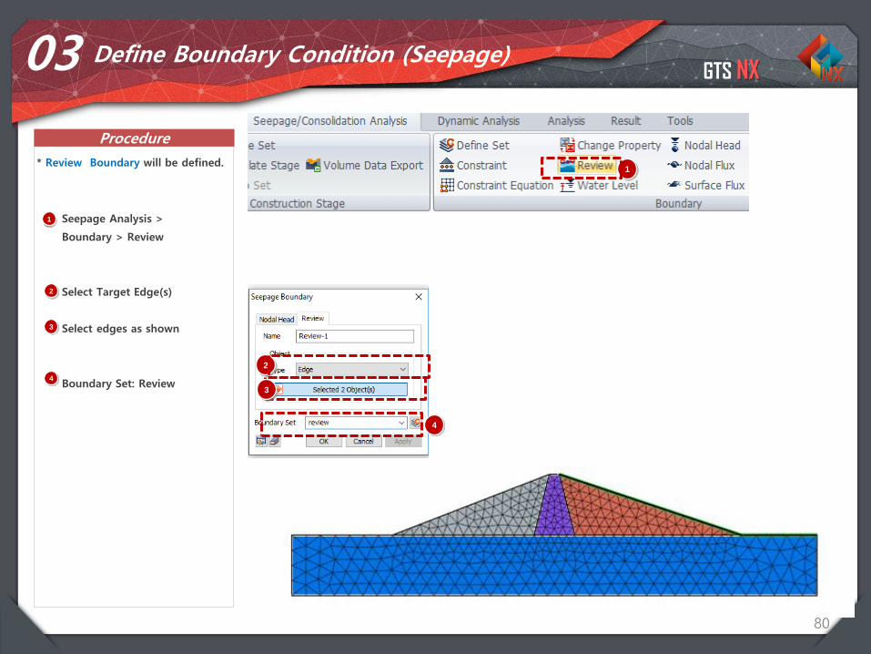
03 Define Boundary Condition (Seepage)
1 Seepage Analysis >
Boundary > Review
Select Target Edge(s)
Select edges as shown
Boundary Set: Review
1* Review Boundary will be defined.
2
3
4
2
3
4
GTS NX
Procedure
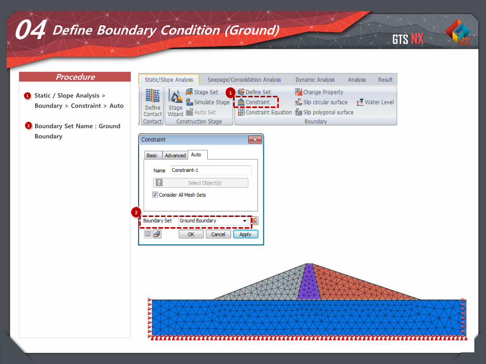
81
04 Define Boundary Condition (Ground)
1 Static / Slope Analysis >
Boundary > Constraint > Auto
Boundary Set Name : Ground
Boundary
1
2
2
GTS NX
Procedure
82
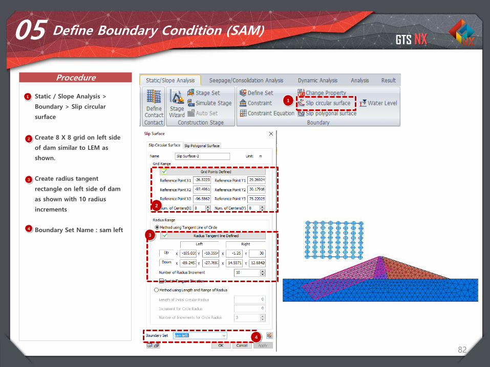
05 Define Boundary Condition (SAM)
1 Static / Slope Analysis >
Boundary > Slip circular
surface
Create 8 X 8 grid on left side
of dam similar to LEM as
shown.
Create radius tangent
rectangle on left side of dam
as shown with 10 radius
increments
Boundary Set Name : sam left
1
2
2
4
3
4
3
GTS NX
Procedure
83
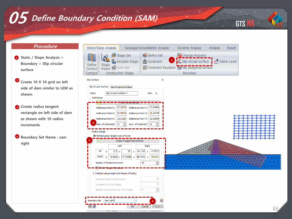
05 Define Boundary Condition (SAM)
1 Static / Slope Analysis >
Boundary > Slip circular
surface
Create 10 X 10 grid on left
side of dam similar to LEM as
shown.
Create radius tangent
rectangle on left side of dam
as shown with 10 radius
increments
Boundary Set Name : sam
right
1
2
2
4
3
4
3
GTS NX
Procedure
84
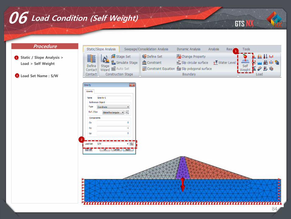
06 Load Condition (Self Weight)
1
1 Static / Slope Analysis >
Load > Self Weight
Load Set Name : S/W2
2
GTS NX
Procedure
85
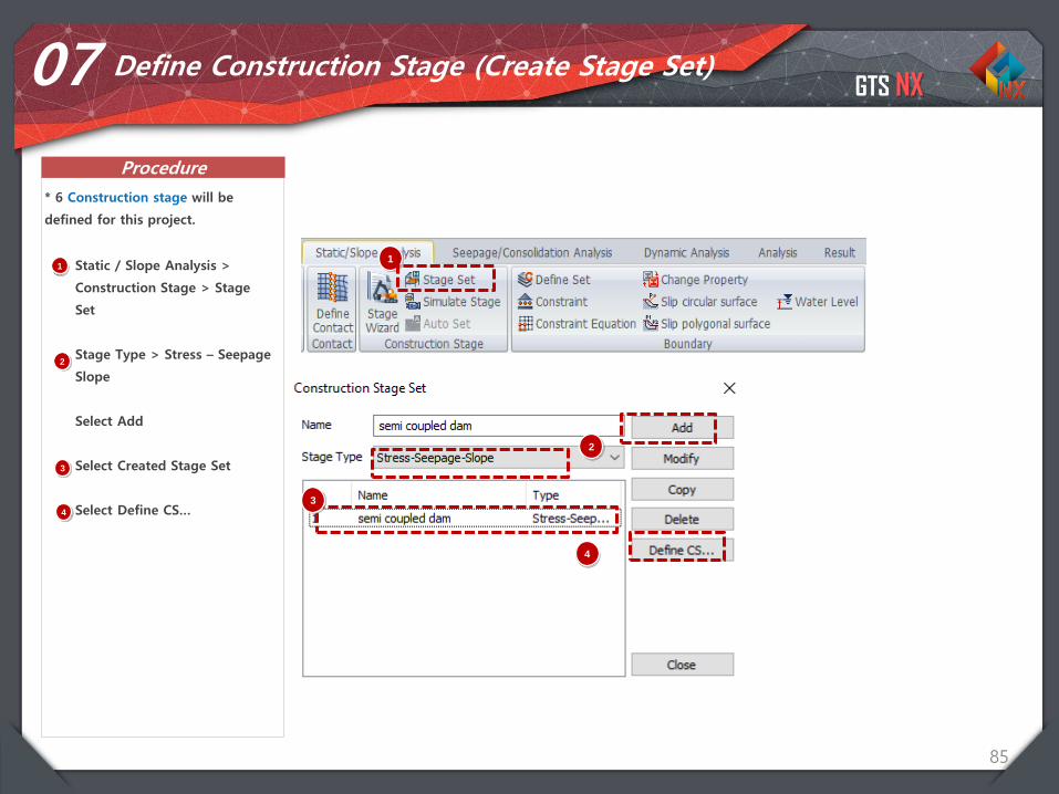
07 Define Construction Stage (Create Stage Set)
1 Static / Slope Analysis >
Construction Stage > Stage
Set
Stage Type > Stress – Seepage
Slope
Select Add
Select Created Stage Set
Select Define CS…
* 6 Construction stage will be
defined for this project.
1
2
2
3
4
3
4
GTS NX
Procedure
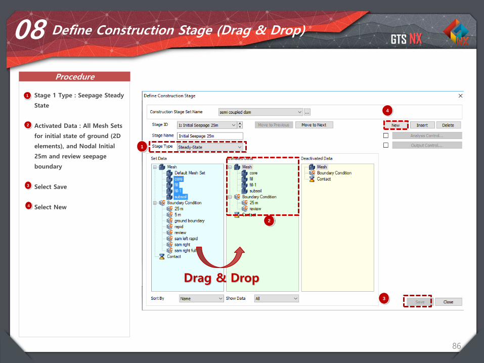
86
08 Define Construction Stage (Drag & Drop)
1 Stage 1 Type : Seepage Steady
State
Activated Data : All Mesh Sets
for initial state of ground (2D
elements), and Nodal Initial
25m and review seepage
boundary
Select Save
Select New
2
1
2
3
4
3
4
Drag & Drop
GTS NX
Procedure
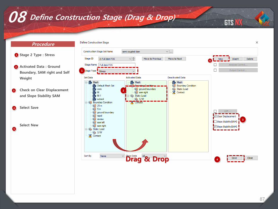
87
08 Define Construction Stage (Drag & Drop)
1 Stage 2 Type : Stress
Activated Data : Ground
Boundary, SAM right and Self
Weight
Check on Clear Displacement
and Slope Stability SAM
Select Save
Select New
2
1
2
3
4
Drag & Drop
3
4
5
5
GTS NX
Procedure
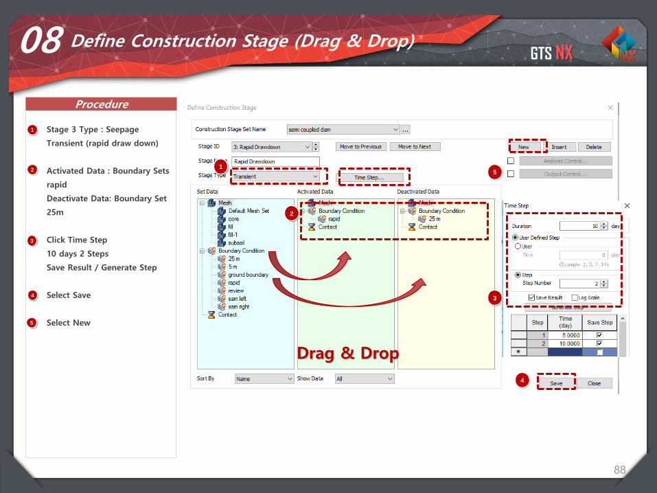
88
08 Define Construction Stage (Drag & Drop)
1 Stage 3 Type : Seepage
Transient (rapid draw down)
Activated Data : Boundary Sets
rapid
Deactivate Data: Boundary Set
25m
Click Time Step
10 days 2 Steps
Save Result / Generate Step
Select Save
Select New
2
12
3
4
Drag & Drop
3
4
5
5
GTS NX
Procedure
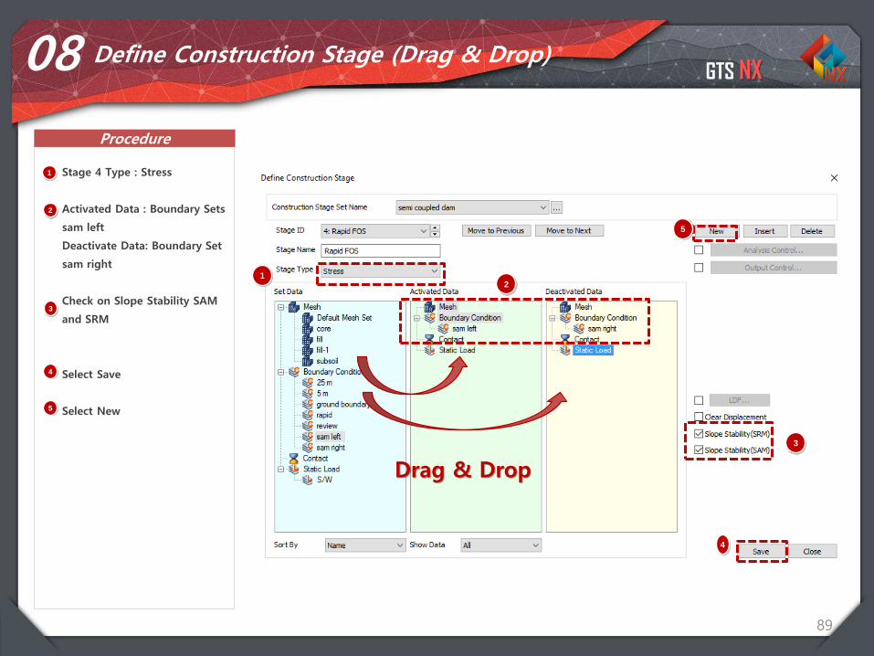
89
08 Define Construction Stage (Drag & Drop)
1 Stage 4 Type : Stress
Activated Data : Boundary Sets
sam left
Deactivate Data: Boundary Set
sam right
Check on Slope Stability SAM
and SRM
Select Save
Select New
21
2
3
4
3
4
Drag & Drop
5
5
GTS NX
Procedure
90
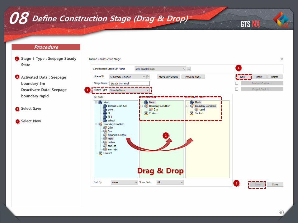
08 Define Construction Stage (Drag & Drop)
1 Stage 5 Type : Seepage Steady
State
Activated Data : Seepage
boundary 5m
Deactivate Data: Seepage
boundary rapid
Select Save
Select New
2
1
2
3
4
3
4
Drag & Drop
GTS NX
Procedure
91
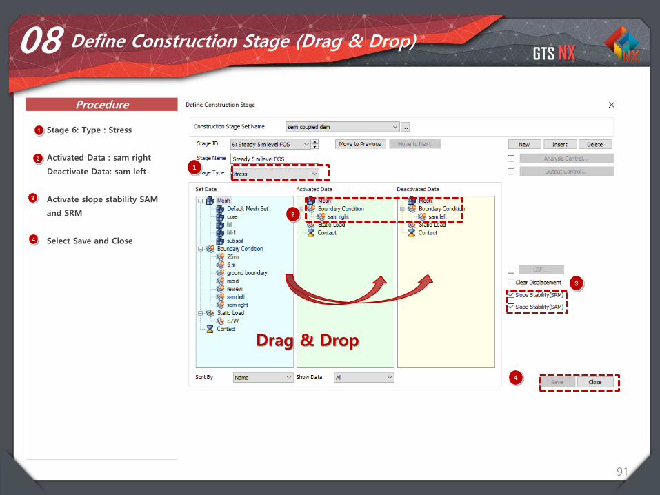
08 Define Construction Stage (Drag & Drop)
1 Stage 6: Type : Stress
Activated Data : sam right
Deactivate Data: sam left
Activate slope stability SAM
and SRM
Select Save and Close
2
1
2
3
4
Drag & Drop
3
4
GTS NX
Procedure
92
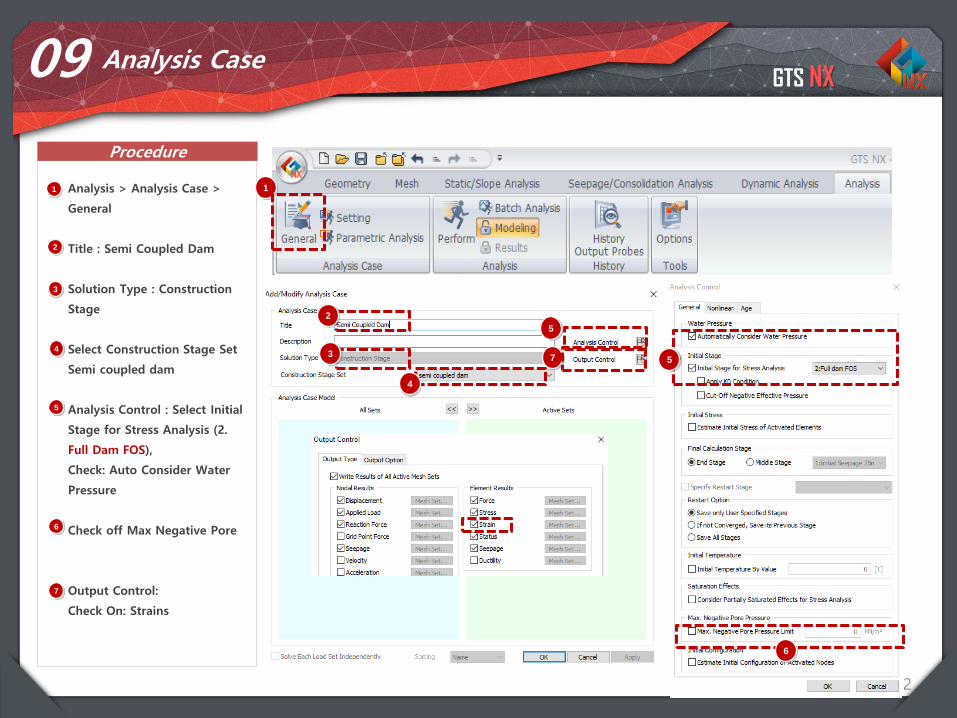
09 Analysis Case
1 Analysis > Analysis Case >
General
Title : Semi Coupled Dam
Solution Type : Construction
Stage
Select Construction Stage Set
Semi coupled dam
Analysis Control : Select Initial
Stage for Stress Analysis (2.
Full Dam FOS),
Check: Auto Consider Water
Pressure
Check off Max Negative Pore
Output Control:
Check On: Strains
1
2
3
4
5
2
3
4
5
5
6
7
6
7
GTS NX
Procedure
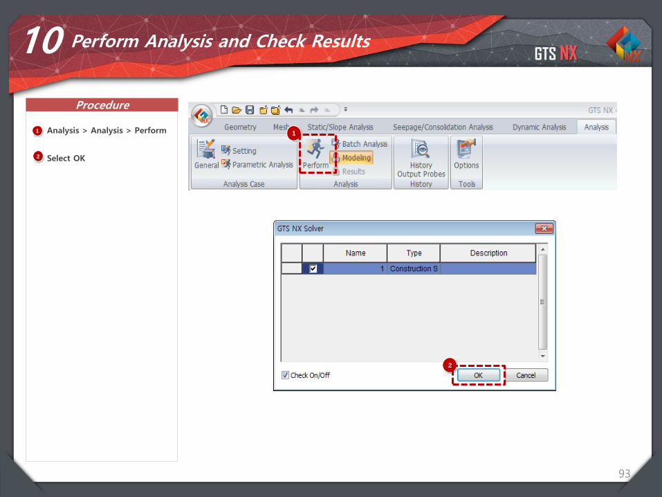
93
10 Perform Analysis and Check Results
1 Analysis > Analysis > Perform
Select OK
1
2
2
GTS NX
Procedure
94
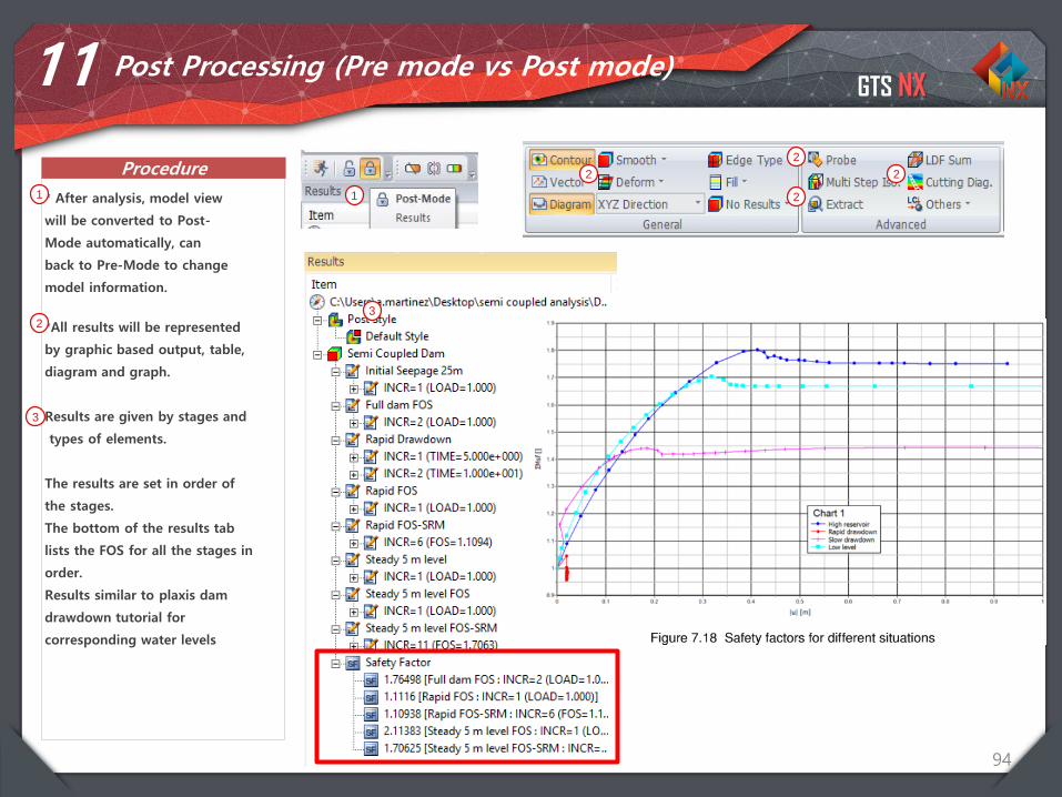
11 Post Processing (Pre mode vs Post mode)
* After analysis, model view
will be converted to Post-
Mode automatically, can
back to Pre-Mode to change
model information.
1 1
*All results will be represented
by graphic based output, table,
diagram and graph.
Results are given by stages and
types of elements.
The results are set in order of
the stages.
The bottom of the results tab
lists the FOS for all the stages in
order.
Results similar to plaxis dam
drawdown tutorial for
corresponding water levels
2
2
2
22
3
3
GTS NX
Procedure
95
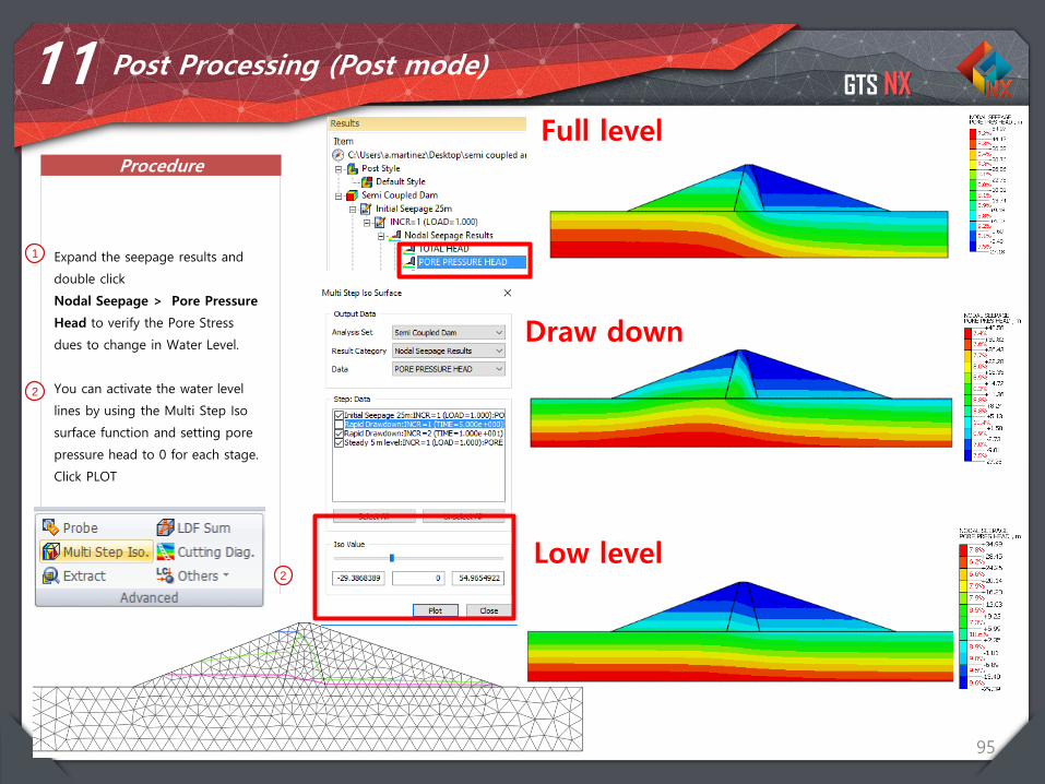
11 Post Processing (Post mode)
1 Expand the seepage results and
double click
Nodal Seepage > Pore Pressure
Head to verify the Pore Stress
dues to change in Water Level.
You can activate the water level
lines by using the Multi Step Iso
surface function and setting pore
pressure head to 0 for each stage.
Click PLOT
2
2
Full level
Draw down
Low level
GTS NX
Procedure
96
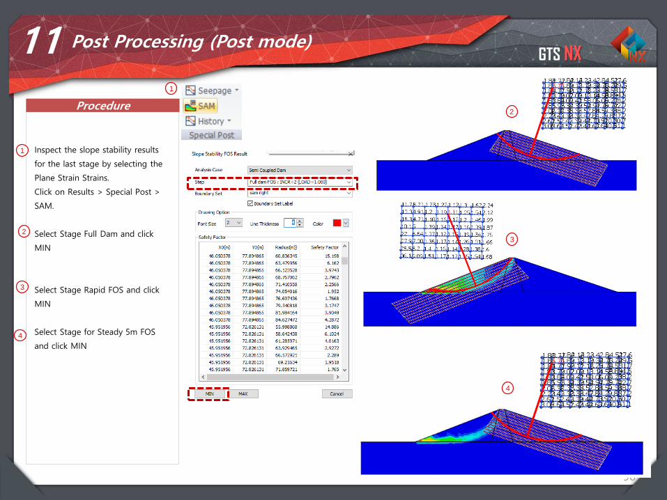
11 Post Processing (Post mode)
1 Inspect the slope stability results
for the last stage by selecting the
Plane Strain Strains.
Click on Results > Special Post >
SAM.
Select Stage Full Dam and click
MIN
Select Stage Rapid FOS and click
MIN
Select Stage for Steady 5m FOS
and click MIN
1
2
3
3
2
4
4

GTS NX
97
Thank you