2d and 3d modeling comparison - bibsys brage
TRANSCRIPT

BACHELOROPPGAVE:
2D and 3D Modeling Comparison
FORFATTER(E): RITA GAIDYTĖ Dato: 27. 05. 2010

2D and 3D Modeling Comparison
Summary Title: 2D and 3D Modeling Comparison Date: 25.06.10 Author: Rita Gaidytė Supervisors: George Preiss, Arminas Stanionis Employer: Høgskolen I Gjøvik Vilnius Gediminas Technical University Contact Person: George Preiss, Arminas Stanionis, Vilma Zubinaitė Attachments: 0 Availability: Open Abstract:
Many inventors and companies still use 2D drawings and are starting to realize a
3D design because 3D modeling can save time and money.
In this project I am going to compare 2D and 3D drawings and modeling. 2D
modeling and 3D modeling have advantages and disadvantages. For this comparison I
made 2D and 3D models using AutoCAD, Autodesk Revit Architectural and Revit
MEP software. So, I am going to compare CAD (Computer-aided design) and BIM
(Building Information Modeling) technologies, because it is related with 2D and 3D
modeling.
2

2D and 3D Modeling Comparison
Preface This report describes results of the bachelor project from student from Lithuania at
Geodesy and Cartography Department at Vilnius Gediminas Technical University
which is writing bachelor thesis at Geomatics Department at Gjøvik University
College. The project includes 20 ECTS.
The project is carried by one bachelor student from Lithuania Vilnius Gediminas
Technical University: Rita Gaidytė. The supervisors of the project are a lecturer at
Gjøvik University College, George Preiss and a lecturer at Vilnius Gediminas
Technical University, Arminas Stanionis.
This project has started on January in Lithuania where I did measurements of my
university for this project. In Gjøvik University College I continued this project from
March.
During this project I have made 3D model of one floor of my University in Lithuania.
I hope it will be interesting and helpful to the workers of my University.
I would like to thank my supervisor George Preiss and Vilma Zubinaitė, for lots of
great ideas and support during my project.
Gjøvik University College, 25 May 2010
Rita Gaidytė
3
2D and 3D Modeling Comparison
4
Contents
Summary .................................................................................................................... 2 Preface ........................................................................................................................ 3 List of Figures ............................................................................................................ 6 List of Tables ............................................................................................................. 6 1. Introduction ......................................................................................................... 7 1.1 Chapter summary ................................................................................................. 7 1.2 Project Definition ................................................................................................. 8 1.3 Project Objectives ................................................................................................ 8 1.4 Background .......................................................................................................... 9 1.5 Project members ................................................................................................. 10 1.5.1 Student’s background...................................................................................... 10 1.5.2 Supervisors background .................................................................................. 10 1.6 Acronyms/Abbreviations ................................................................................... 10 2. Background and literature review ..................................................................... 11 2.1 Introduction ........................................................................................................ 11 2.2 Computer-aided design (CAD) .......................................................................... 11 2.3 Building Information Modeling (BIM) .............................................................. 12 2.4 How BIM is different from CAD ....................................................................... 13 3. Equipment ......................................................................................................... 16 3.1 Leica DISTO D2 ................................................................................................ 16 3.2 Software ............................................................................................................. 17 3.2.1 AutoCAD ........................................................................................................ 17 3.2.2 Autodesk Revit................................................................................................ 17 3.2.4 Other software ................................................................................................. 18 3.2.4.1 Microsoft Office Word ................................................................................. 18 3.2.4.2 Paint ............................................................................................................. 18 4. Processing and Analysis ................................................................................... 19 4.1 Measurements in Lithuania ................................................................................ 19 4.2 BIM Modeling ................................................................................................... 22 4.2.1 The importing of 2D model to Autodesk Revit Architecture .................... 22 4.2.2 SlimBIM .................................................................................................... 22 4.2.3. BuildingSMART ............................................................................................ 23 4.2.4 The Final Result .............................................................................................. 26 4.3 Other BIM possibilities ................................................................................. 28
2D and 3D Modeling Comparison
5. Difficulties ........................................................................................................ 29 6. Conclusions and Recommendations ................................................................. 30 7. Bibliography ..................................................................................................... 33 8. Appendixes ....................................................................................................... 34 Appendix A. Mechanical Equipment Schedule ....................................................... 34 Appendix B. Mechanical Equipment Material Takeoff. .......................................... 35 Appendix C. Floor Schedule .................................................................................... 36 Appendix D. Stair and Railing Schedules. ............................................................... 37 Appendix E. Window Schedule. .............................................................................. 38
5

2D and 3D Modeling Comparison
List of Figures Figure 1. CAD system................................................................................................. 11 Figure 2. A CAD project consists of many uncorrelated, independently created files....................................................................................................................................... 13 Figure 3. The BIM model is a centralized data-base in which all documents are independent. ................................................................................................................. 14 Figure 5. Minimum/maximum measurements, tracking and storage of results. ......... 16 Figure 4. Leica DISTO D2. ......................................................................................... 16 Figure 6. Materials of constructions. .......................................................................... 19 Figure 7. A plan of the second floor. .......................................................................... 20 Figure 8. Results of measurements. ............................................................................ 20 Figure 9. Results of measurements. ............................................................................ 21 Figure 10. 2D model. .................................................................................................. 21 Figure 11. Importing of 2D CAD model to Revit Architecture. ................................. 22 Figure 12. SlimBIM .................................................................................................... 22 Figure 13. 3D view with switches, sockets and ventilation. ....................................... 26 Figure 14. Connected second and third floors. ........................................................... 26 Figure 15. 3D view of connected floors ...................................................................... 27 Figure 16. Elevations of connected floors. ................................................................. 27
List of Tables Table 1. CAD and BIM technologies comparison. ...................................................... 15 Table 2.Software based on BIM technologies. ............................................................ 17 Table 3. Door Schedule................................................................................................ 23 Table 4. Door Material Takeoff. .................................................................................. 24 Table 5. Room Schedule. ............................................................................................. 25
6

2D and 3D Modeling Comparison
1. Introduction
1.1 Chapter summary Chapter 1 – Introduction
Provides background information about the project and participant of the project. It
also gives an overall overview of the project structure.
Chapter 2 – Background and Literature Review
An overview and description of relevant theory knowledge used during the research
project.
Chapter 3 – Equipment
An overview of equipment used on the project and short description of the equipment
and an overview of software.
Chapter 4 – Processing and Analysis
An overview of measurements in Lithuania and work in Gjøvik.
Chapter 5 – Difficulties.
An overview of difficulties during the project.
Chapter 6 – Conclusions and Recommendations
Conclusion of the project including key points and main findings. Opinions,
suggestions and recommendations.
Chapter 7 – Bibliography
An overview of all literature researched during the project.
Chapter 8 – Appendixes
An overview of some appendixes to the report.
7

2D and 3D Modeling Comparison
1.2 Project Definition The main aim of this Project is to sift advantages and disadvantages of 2D and 3D
modeling using AutoCAD, Autodesk Revit Architecture and Revit MEP software in
CAD and BIM technologies. In this project I used measurements which were made in
Lithuania of Vilnius Gediminas Technical University. The measurements I did with
laser distance meter Leica D2. Using those measurements I have drawn 2D model
with AutoCAD software and 3D model with Autodesk Revit Architecture and Revit
MEP software.
A written report will be delivered to the school on 28th of May. Project presentation
will be held on 3th June 2010 in Gjøvik University College.
I will try to answer these questions:
Is 3D modeling better than 2D?
If yes:
Whom is 3D modeling better?
What are advantages and disadvantages of CAD and BIM technologies?
1.3 Project Objectives The main aim of this project is to sift advantages and disadvantages of 2D and 3D
modeling using AutoCAD, Autodesk Revit Architecture and Autodesk Revit MEP
software, and to compare BIM and CAD technologies.
8

2D and 3D Modeling Comparison
1.4 Background A number of decisions have to be made which directly affect the product's
overall and total cost. One of the first decisions that has to be made deals with
the initial design. The engineering, design and drafting world has been
experiencing a shift from 2D to 3D views. Many inventors and companies still use
2D drawings and are starting to realize 3D modeling because it can save time and
oney. m
Making 2D drawings is fast and easy, but the output is still a 2D drawing which
does not readily work with downstream systems. In some cases 2D drawings are
sufficient but most of the time they are not. In fact, the majority of the buildings
need 3D files and it is difficult read 2D drawings because 2D drawings do not
ontain all information needed to develop a 3D product. c
Unlike 2D drafting, parametric 3D modeling is particularly useful at the early
stages of design, where engineering skills are required. The main difference
between 3D modeling and 2D drafting is that buildings are modeled rather than
drawn.
9

2D and 3D Modeling Comparison
1.5 Project members
1.5.1 Student’s background I, Rita Gaidytė, am from Vilnius, Lithuania. I came three months ago as an
international student to write bachelor thesis. In Lithuania I am studying in Vilnius
Gediminas Technical University, at faculty of Environmental Engineering,at
department of Geodesy and Cadastre. Also I have about one year work experience in
geodetic company UAB ‘Inžineriniai tyrinėjimai‘ (‚Engineering Researches‘).
1.5.2 Supervisors background George Preiss comes from Great Britain. He has a long experience within surveying
and GPS system. During his carrier he was a chairman at International Information
Sub/Committee of the US Department of transportation Civil GPS Service Interface
Committee, for 9 years. He also worked as a GPS consultant for Statens Kartverk for
8 years. Currently he is working as an associated teacher for the Gjøvik University
College, Faculty of Technology, and Department of Geomatics.
Arminas Stanionis is from Vilnius, Lithuania. Since 2003 year he is working as a
teacher in Vilnius Gediminas Technical University, Faculty of Environmental
Engineering, and Department of Geodesy and Cartography.
1.6 Acronyms/Abbreviations CAD Computer-aided design
BIM Building Information Modeling
2D Two-dimensional
3D Three-dimensional
10

2D and 3D Modeling Comparison
2. Background and literature review
2.1 Introduction
Now buildings are more complex than ever before, because today we have more
telecom, security, electrical, data and energy requirements. Earlier documentation sets
were hundreds of pages long. People who touched these sets of drawings had become
huge, because they had to produce them, evaluate them or use them to build the
building. But the computer-based technology has replaced pen and paper. Drawing
and editing lines is faster and more efficient. But these lines and text are not
intelligent lines and text. They are still collections of manually created.
2.2 Computeraided design (CAD)
Computer-aided design (CAD) is the use of computer technology for the design of
real and virtual objects. CAD is 2D technology that outputs a collection of lines and
text on a page. These lines have no inherent meaning in the computer or on the
printed sheet. Of course, CAD has its advantages over pen and paper, but it is still a
digital modeling of the act of drafting. This form of drawing shows us how architects,
engineers and designers have worked for the last hundred years. Earlier designers
drew plans manually. It was inconvenient, because if any items changed, the designer
had to modify each of the other drawings that were affected to take the change into
account. In our days we can use Delete key, but the goal is the same (figure 1). So,
here BIM makes important departure from CAD platforms.
Figure 1. CAD system
11

2D and 3D Modeling Comparison
2.3 Building Information Modeling (BIM) BIM is beginning to change buildings: how they look, the way they function, the ways
in which they are built. BIM is not a type or a thing of software but a human activity
that involves wide process changes in construction. BIM must be: digital, spatial,
measurable, comprehensive, accessible and durable. In BIM all elements are loaded
with data that describe not only geometry, bur also material, fire rating, cost,
manufacturer, count, and just about any other metadata you can imagine.
Now we can have all disciplines involved with a project sharing a single database:
Architecture, structure, mechanical, infrastructure and construction now can
be coordinate in ways, not to be together.
Models can now be sent directly to fabrication machines.
Energy analysis can be done at the outset of design.
Construction costs are becoming more predictable.
BIM regards how designers and constructors look at the all building process: from
preliminary design through construction documentation, into actual construction and
even into postconstruction building management. With BIM usual 3D model is used
to generate traditional building abstractions: plans, sections, details, elevations and
schedules. Drawings produced using BIM are not just collections of lines and
coordinates but interactive view of a model.
A work with a model-based framework is easier and very convenient because it
guarantees that a change in one view will propagate to all other views of the model. If
you remove a window from the model, it simultaneously is removed from all views
and your window schedule is updated. If you move elements in plan, they change in
elevation and section.
12

2D and 3D Modeling Comparison
2.4 How BIM is different from CAD
The biggest difference between BIM and CAD is that a CAD system, especially 2D,
uses many separate documents to explain a building. For example, the wall view is
represented with two parallel lines, and we can’t understand that those lines represent
the same wall in a section. BIM assembles all information into one location. It is a
centralized database model. In the BIM all documents are interdependent and share
intelligence. (Figures 2 and 3).
Figure 2. A CAD project consists of many uncorrelated, independently created files.
13

2D and 3D Modeling Comparison
The best thing in BIM is that it manages changes for you. If we do change in the
project in one place, the system will change all relevant views and documents of the
project. If we change size of a window opening in elevation, this change is made
throughout sections, floor plans and schedule tables.
Figure 3. The BIM model is a centralized data-base in which all documents are independent.
Here are five big differences between BIM and CAD:
BIM adopts a task-oriented more quickly than an object-oriented
methodology. In 2D drafting the wall we draw with two lines. In BIM, a wall
is presented like a tool named Wall. This wall has height, width, bearing or
nonbearing, interior or exterior, materials, fire rating, demolished or new. If
we add a door, in BIM it’s more than four lines like in 2D drafting. Adding
doors to wall automatically creates an opening in the wall in all views where
are the doors.
14

2D and 3D Modeling Comparison
BIM keeps us honest. One of BIM advantage is that we can’t cheat design,
because the elements have properties based on real-life properties. If we have
a window in plan, it automatically appears in the other associated views, such
as elevation or section. In a CAD system it can be easy to overlook because
we can forget to draw a window in the place or can draw it at a wrong
location.
BIM is more than a 3D modeler. Usual modeling doesn’t have the ability to
document a design for construction or to be leveraged. But it is possible to
bring a model into a BIM application and progressed through design, analysis
and documentation.
BIM is a data-driven design tool. BIM lets you create custom content and
libraries. This content contains a rich amount of data that will inform
schedules, quantity take-offs, and analysis. So, it is not also just 3D – it is 3D
with intelligent information.
BIM is based on an architectural classification system, not ,,layers”. In CAD
every line belongs to a layer. It is a reason that we can to place, for example a
window, into not correct layer. For example, in Revit, there is no way to
accidentally place a window into ‘wall’ layer.
In the table 1 we can see more differences between CAD and BIM: Table 1. CAD and BIM technologies comparison.
PROPERTIES CAD BIM
Views which have communications -
Parametric solutions -
Automated tables -
Drawing 2D
DWG compatibility
Supplementary drawings support
Lines thicknesses, types and patterns
Visibility management
Auto zoom control -
One of the project database in a file -
15

2D and 3D Modeling Comparison
3. Equipment Equipment
3.1 Leica DISTO D2 3.1 Leica DISTO D2 The measurements I did with laser distance meter Leica DISTO D2 (figure 4). The measurements I did with laser distance meter Leica DISTO D2 (figure 4).
The Leica DISTO D2 has a versatile measuring range of 0.05 meters to 60 meters,
which lets you use it for almost any task you can think of. The accuracy is ± 1.5 mm.
With Leica DISTO D2 to measure is not difficult:
measure distances at the touch of the button and
calculate areas and volumes, with the flip-out end-
piece you are equipped for any measuring situation,
the results are shown on a 3-line display, minimum /
maximum measurements, tracking and storage of
results (figure 5).
Figure 5. Minimum/maximum measurements, tracking and storage of results. Figure 5. Minimum/maximum measurements, tracking and storage of results.
Figure 4. Leica DISTO D2.
16

2D and 3D Modeling Comparison
3.2 Software
3.2.1 AutoCAD AutoCAD - a universal Autodesk company created and developed computer-aided
design system. AutoCAD purpose is to draw drawings, to simulate the complex flat
and dimensional constructions, which are using in construction, controversy, electrical
engineering, maps and furniture design and etc.
In AutoCAD system are basis more than 2000 specialized software products for
houses, cities, robot, machines, building construction, utility and communication,
roads and streets, maps and for other objects design.
3.2.2 Autodesk Revit There are a lot of software based on BIM technologies (table 2): Table 2.Software based on BIM technologies.
SOFTWARE PRODUCER Revit Autodesk Navit Works JetStream Autodesk ArchiCAD Graphisoft Constructor Graphisoft Bentley Architecture Bentley Systems Digital Project Gehry Technologies LLC Vector Works Architect Nemetschek N.A Tekla Structures Tekla Corporation SPIRIT SOFTTECH GmbH StruCAD AceCAD Software Inc IFC Engine Series TNO
For 3D modeling I chose Revit Architecture and Revit MEP software, because Revit
is the most technologically BIM application. The name Revit comes from ,,Revise
Instantly”. Revit is built for managing change. This software was designed from the
ground up as a BIM platform to specifically address problem areas of the architecture,
engineering and construction industry: communication, coordination and change
management. In CAD users have to do a lot of manual updating, but Revit
understands when a change happens and does it automatically.
17

2D and 3D Modeling Comparison
Revit has a lot of advantages, but sometimes, if we are not careful, this can also be
disadvantages, especially for users who may be quick to make changes. Revit creates
relationships between building elements in order to streamline the design process. For
example, if we will delete a wall, all windows, doors and other elements will be
deleted. But beauty of Revit is that it will not let you leave elements floating around.
3.2.4 Other software
3.2.4.1 Microsoft Office Word Microsoft Office word was used to write all draft documents and the final report.
3.2.4.2 Paint Paint was used for modeling of figures.
18

2D and 3D Modeling Comparison
4. Processing and Analysis
4.1 Measurements in Lithuania In January I started my Project from measurements of Vilnius Gediminas Technical
University, faculty of Environmental Engineering in Lithuania. I measured second
floor. These measurements were not like usual cadastral measurements, because I had
to measure this floor for 3D model. It means that I had to measure not only length of
walls but every detail in all rooms: sockets, switches, lamps, all cords which we see
and other things. Also I had to know all materials of walls, floors, ceilings. This
information I have got from my university (figure 6). Also I have got a plan of second
floor (figure 7). I had to gather all information what needs Building Information
Modeling.
Figure 6. Materials of constructions.
19

2D and 3D Modeling Comparison
Figure 7. A plan of the second floor.
For measurements I didn’t use any coordinate system. I used laser distance meter
(Leica DISTO D2) and a roulette if wasn’t possibilities to measure with laser distance
meter. All measurements I wrote on the paper (figure 8 and 9).
Figure 8. Results of measurements.
20

2D and 3D Modeling Comparison
Figure 9. Results of measurements.
When I had results of measurements I drew 2D model with AutoCAD software
(figure 10). With AutoCAD software I have more than three years work experience,
so to draw 2D model of one floor for me wasn’t too difficult.
Figure 10. 2D model.
21
2D and 3D Modeling Comparison
4.2 BIM Modeling
4.2.1 The importing of 2D model to Autodesk Revit Architecture
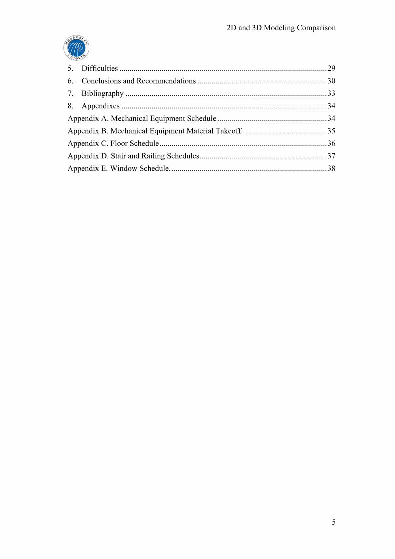
One more a beauty of Revit is that we can import and export to a predefined set of
layers. I have imported my 2D CAD model to Revit very easy and quickly (figure 11).
Figure 11. Importing of 2D CAD model to Revit Architecture.
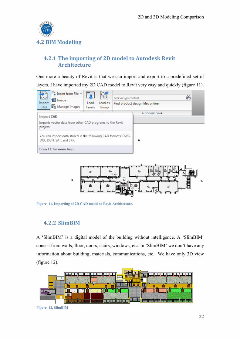
4.2.2 SlimBIM
A ‘SlimBIM’ is a digital model of the building without intelligence. A ‘SlimBIM’
consist from walls, floor, doors, stairs, windows, etc. In ‘SlimBIM’ we don’t have any
information about building, materials, communications, etc. We have only 3D view
(figure 12).
Figure 12. SlimBIM
22

2D and 3D Modeling Comparison
4.2.3. BuildingSMART BuildingSMART is a digital model with intelligence. If we want to get a full BIM
model, we have to put in all information about building, constructions,
communications and other details. Type of information depends from drawer, because
he can put, create all information which he needs and thinks that it is important.
For example, I tried to put and to create all information that everybody could find
information which is required them. For example: electrician - about electricity,
plumber - about heaters, communications.
All information in Revit is in schedules (table 3). To create schedules is very easy and
quickly. We can choose fields and create new fields if we think that they are required. Table 3. Door Schedule.
One more power of Revit is, when we place a door in the model it is automatically
tagging with a sequential door number. The same is with windows. In table 3 we can
see door schedule. The dimensions of the doors are creating automatically, so I hadn’t
to write one by one. But, for example, model, company, I had to write in. But it is
obviously, because software can’t know these things. This schedule can help for
23

2D and 3D Modeling Comparison
everybody. For example, if we broke door, we can open door schedule and see model
of the door and company which produce those doors. So, we just go to the shop and
say that we need this door, with this dimensions, etc.
But schedules do not stop just at doors and windows. We can schedule almost any
item that goes into the model. (Appendixes).
Next step of creating buildingSMART is creating material takeoffs. It is similar to
creating a schedule. The only difference is that we are now breaking components
down and scheduling the smaller pieces (table 4). For example, we could get a
schedule of the all o the doors. But with material takeoff, we can quantify the glass
within the doors, the square footage of door panels. Table 4. Door Material Takeoff.
24

2D and 3D Modeling Comparison
One more thing in Revit which I like very much is that we can create room areas
plans. There we can write names of rooms. And later we can create Room Schedule
(table 5). In Room Schedule we can create all information about each room. We can
see floor finish, wall finish, ceiling finish and other information which is required for
us. It is very easy, quickly and informative. Table 5. Room Schedule.
So, I can say that all information in buildingSMART can be classified to: ‘must have’,
‘ought to have’, or just ‘nice to have’.
In smart model we also must have energy. For energy and communications I used
Revit MEP software, because in Revit Architecture wasn’t switches, sockets, cables,
ducts, etc (figure 13).
25
2D and 3D Modeling Comparison
Figure 13. 3D view with switches, sockets and ventilation.
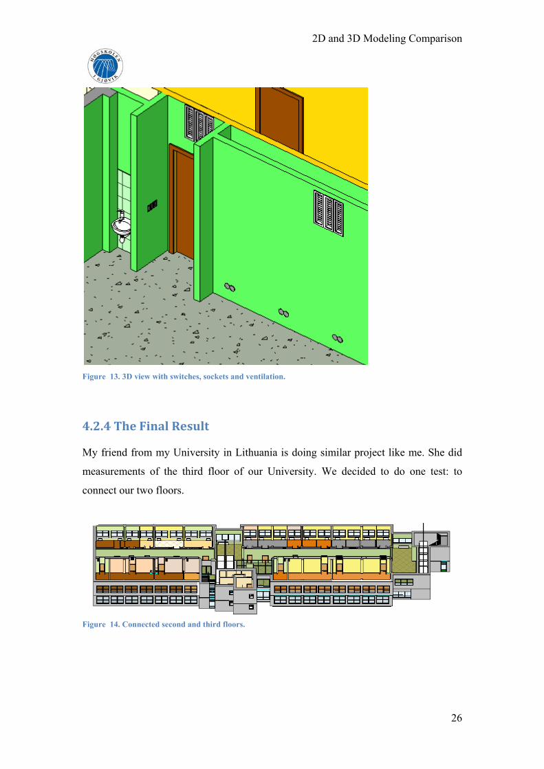
4.2.4 The Final Result My friend from my University in Lithuania is doing similar project like me. She did
measurements of the third floor of our University. We decided to do one test: to
connect our two floors.
Figure 14. Connected second and third floors.
26

2D and 3D Modeling Comparison
Figure 15. 3D view of connected floors
Figure 16. Elevations of connected floors.
This two floors connection shows for us that with Revit we can connect the works of
different persons. It lets for us to make projects faster.
27

2D and 3D Modeling Comparison
4.3 Other BIM possibilities
Building Intelligent Modeling can be used not only for buildingSmart. With BIM we
can designed, for example, an intelligent ‘industry park model’ which can be used for
planning and to have information about size, main dimensions and number of rooms,
floor bearing weight restrictions, driving route to the building from the main gates,
driving route to come out again, which services are available – power, gas, water,
remote heating, telephone, etc. It means that we can create not only building, but also
the area near the building.
I created buildingSMART for existing building. But we also can create
buildingSMART for new buildings which are not built. For existing buildings to
create a buildingSMART model is difficult, because we have to measure a building,
to know, for example, all cables of telephone, internet and other communications. It
needs a lot of time and expenditure before we start to create a BIM model. In my
opinion, for not existing buildings is easier to create BIM model, because we need
only drawing, project whereby we can create buildingSMART.
28

2D and 3D Modeling Comparison
5. Difficulties
During this project I had some difficulties:
The first difficulty was that I didn’t measure lamps. But later I understood that
I can draw lamps from the pictures and when I will back to Lithuania I can
measure and correct lamps by precisely measurements, because Revit let for us
to do it quickly and easy.
First weeks were very difficult to understand the new software and how to
work with it, because before I hadn’t experience with buildingSMART
software.
Next difficulty was that I couldn’t draw sockets, switches, cables, because
Revit Architecture hadn’t, so I had to fix Revit MEP software and through very
short time to learn how to use this software.
Revit is American software, so there are some words from American English
language.
The most difficult was to connect two floors, because measurements and
drawing were did by two different students (me and my friend).
29

2D and 3D Modeling Comparison
6. Conclusions and Recommendations
This project is based on comparing 2D and 3D modeling by of BIM and CAD
technologies. The aim of this analysis was to find out the merits and demerits of these
two presented technologies. Nowadays it is very important to save the resources of
time and to make the best result which could be used from various companies of
industry to the users.
To understand which software is the best, there was made a 2D model by AutoCad
and 3D model by Autodesk Revit software. The process of this was to carry out the
measurements of already built building, which is Vilnius Gediminas Technical
University in Vilnius, Lithuania. There was measured the second floor, and all
available information was collected starting from the electricity switches to the
material of walls. These data were processed by the software mention above.
Conclusions and recommendations are:
Both software are applicable for building modeling. They have a lot of
properties to create as real a model as possible. They both produce the main
objects, as walls, doors, windows and etc. But it was noticed - that using
AutoCad there was not the possibility to create families. With the help of
families we can easy change various minor details as desired. For example,
door hardware and frame jamb.
3D design we can understand easily because we see and know what windows
or doors, and other details look like. It is not just lines like in a 2D model.
Also, not everyone can understand 2D, because we have to know how we
draw windows, doors, and what the symbols mean.
3D design gives for us the ability to show a variety of design options to the
team and client. For example, if a client can see a 3D buildingSMART model
of his future house, he can change the colors of walls, the style of doors and
other things and see what the result look like.
In Revit Architecture schedules of building components can be automatically
produced, and improve the calculation of costs and quantities.
In Revit material quantity take-offs allow for better planning and
predictability, because in the table we can see which kind of materials we
need, how much materials we need and where we need them.
30
2D and 3D Modeling Comparison
BuildingSMART model we can create for already existing buildings and for
yet not existing buildings. For existing buildings we need more work, more
time, because we have to measure the building before creating a
buildingSMART model. For not existing buildings we need only project of the
future building.
Popular AutoCAD software with 2D modeling is universal, it is good to learn
to draw, to do small-scale projects. But Building Information Modeling lets
for us not just to do, but to create and to model projects. The goal of BIM is to
control calculations and interaction of elements in software systems, because it
is more quick, more accurate and easier for us.
2D modeling has one advantage: to draw 2D model is very quick.
Disadvantages are that in 2D model, in CAD technologies we have only
drawing (lines and text) without information about building. Of course, in
AutoCAD we have layers, for example stairs layer, windows layer, doors
layer. But we can’t see how they look visually. However in Revit in 3D
model we can see every detail of doors or other details.
So, 3D modeling needs more time for design than 2D modeling, because there
we have to reduce more information. Also 3D modeling costs more than 2D
modeling, because with 3D model work more people and longer time, what
needs bigger salary.
However, because these both software, are using in these days, and look that more
and more architects, and the others companies, which are connecting with it, I
recommend in the future the Cadastral measurements have to be in 3D model like the
buildingSMART. Of course, for owners, in my opinion, would be better to have a 2D
model on the paper, because it is easy to use. But a 3D model, especially
buildingSMART, would be useful for electricians, plumbers and other house
supervisors, because in buildingSMART model everybody can find the required
information. For example, if we have a digital 3D buildingSMART model of our
house, when we want to make changes of our house, we can go to architect with a
digital model for consultation. It needs less time and money, because the architect
hasn’t to come to us.
31

2D and 3D Modeling Comparison
But I understand that the world needs more time for changes. In my opinion a lot of
people, companies and institutions still will use 2D modeling some years more,
because changes come step by step. I also still will use 2D modeling in the job, in my
university, because I can’t change software in job or education system in university.
But for myself, for my interest and my future projects I will use 3D modeling,
because to begin to use 3D modeling now is investment to the future.
32

2D and 3D Modeling Comparison
7. Bibliography
1. Wing E. Revit Architecture 2010. No Experience Required, 2009.
2. Dzambazova T., Krygiel E., Demchak G., Introducing Revit Architecture
2010. BIM for Beginner, 2009.
3. Demchak G., Dzambazova T., Krygiel E., Mastering Revit Architecture 2010,
2009.
4. Eastman Ch., Teicholz P., Sacks R., Liston K., BIM Handbook. A Guide for
Building Information Modeling for Owners, Managers, Designers, Engineers,
and Contractors, 2008.
5. About AutoCAD software, http://www.scribd.com/doc/6571125/Apie-
AutoCad-Programa, May 2010.
6. CAD and BIM technologies in building drafting,
https://info.vgtu.lt/upload/leid_konf/jociene_99-107.pdf, May 2010.
7. Building Information Modeling,
http://www.autodesk.de/adsk/servlet/index?id=9976276&siteID=123112, May
2010.
8. BuildingSMART, http://www.buildingsmartalliance.org/index.php/about/,
May 2010.
9. BuildingSMART, http://www.buildingsmart.no/about_us/, May 2010.
10. BuildingSMART, http://www.buildingsmart.org.uk/, May 2010.
11. BuildingSMART, http://buildingsmart.com.au/aboutus, May 2010.
12. BuildingSMART,
http://www.buildingsmart.de/conference2006/announcement.htm, May 2010.
13. BuildingSMART, http://buildingsmart.org.au/, May 2010.
14. Building Information Modeling, http://www.bentley.com/en-
US/Promo/High+Performance+Building+Design/BIM+in+Practice.htm, May
2010.
15. Building Information Modeling,
http://www.gsa.gov/Portal/gsa/ep/contentView.do?contentType=GSA_OVER
VIEW&contentId=20917, May 2010.
16. CAD, http://www.cad.com.au/by-category/buildings/architecture.htm, May
2010.
33

2D and 3D Modeling Comparison
8. Appendixes
Appendix A. Mechanical Equipment Schedule
34

2D and 3D Modeling Comparison
Appendix B. Mechanical Equipment Material Takeoff.
35

2D and 3D Modeling Comparison
Appendix C. Floor Schedule
36

2D and 3D Modeling Comparison
Appendix D. Stair and Railing Schedules.
37

2D and 3D Modeling Comparison
38
Appendix E. Window Schedule.