2d input for virtual reality enclosures with magnetic ...kentlyons.net/pubs/cardboard-iswc16.pdf ·...
TRANSCRIPT

2D Input for Virtual Reality Enclosureswith Magnetic Field Sensing
Kent LyonsTechnicolor Research
175 S. San Antonio Rd. Suite 200, Los Altos, CA [email protected]
ABSTRACTVirtual Reality enclosures are inexpensive devices that createa virtual reality experience using a mobile phone. For exam-ple, Google Cardboard lets a user put their phone inside thedevice and is made from cardboard, some simple lens and amagnet. Because the phone is encased, there is no way to in-teract with the touch screen. Cardboard uses its magnet, thephone’s magnetometer and an algorithm to create a binary in-put [10]. In this paper, we extend the capabilities of thesedevices to provide continuous 2D input. In particular, we usemagnetic field sensing to track the magnet in 2D on the sideof the enclosure. We provide background on magnetic fieldsensing and show how it can apply to a VR enclosure. Weexamine several parameters that impact calculating the mag-net’s position and we focus on the challenge of dealing withthe ambient geomagnetic field. Finally, we present a solutionwhich uses the phone’s inertial sensors and some user inter-actions that take advantage of 2D input with the magnet.
Author KeywordsMagnetic field sensing; input; Google Cardboard; virtualreality
ACM Classification KeywordsH.5.2. Information Interfaces and Presentation: User Inter-faces. - Graphical user interfaces
INTRODUCTIONVirtual Reality (VR) enclosures for smartphones have be-come an inexpensive way to provide simple VR experiencesto end users. Such enclosures are relatively cheap and there-fore allow users to gain access to virtual reality without in-vesting in dedicated hardware. One challenge with thesetypes of devices is how to obtain input from the user. Thephone is surrounded by the enclosure so the touch screen isnot available. Likewise, the inertial sensors are used to trackhead rotations and are largely unavailable for direct user in-put. An additional complication is in keeping the enclosure
Permission to make digital or hard copies of all or part of this work for personal orclassroom use is granted without fee provided that copies are not made or distributedfor profit or commercial advantage and that copies bear this notice and the full citationon the first page. Copyrights for components of this work owned by others than theauthor(s) must be honored. Abstracting with credit is permitted. To copy otherwise, orrepublish, to post on servers or to redistribute to lists, requires prior specific permissionand/or a fee. Request permissions from [email protected] ’16, September 12–16 2016, Heidelberg, Germanyc� Copyright is held by the owner/author(s). Publication rights licensed to ACM.
ISBN 978-1-4503-4460-9/16/09...$15.00DOI: http://dx.doi.org/10.1145/2971763.2971787
Figure 1. Our test apparatus with HMC588L magnetometer, LSM6DS3accelerometer/gyroscope and Arduino (top). A Google Cardboard mod-ified to allow the magnet to move across the entire side panel (bottom).
as simple and cheap as possible. For example, while it wouldbe possible to incorporate a touch panel in the side of the en-closure (similar to Google Glass), doing so would make theenclosure more expensive and complex because it would re-quire adding electronics to a device that is otherwise just asimple mechanical housing and cheap lenses.
The first generation of Google Cardboard offers a unique so-lution to address the problem of input. Cardboard uses perma-nent magnets placed on the enclosure, and with the phone’smagnetometer, it senses the user sliding a magnet to create abinary button press input [10]. While this approach is effec-tive, it offers very minimal input capabilities.
In this paper, we extend the idea of using a magnet attached tothe outside of a VR enclosure, but provide for continuous 2Dinput. As we will detail, previous work has tracked a magnet

using multiple magnetometers. However, only one of thesesensors is available in smartphones. We provide an analysisof parameters impacting magnetic field (MF) sensing for VRenclosures and highlight the issue of accounting for the am-bient geomagnetic field. We demonstrate an approach whichuses a single magnetometer and the other sensors available inmobile phones. We implement this using stand alone sensinghardware, as well as on an iPhone inside a Unity3D card-board app. Finally, we propose some interactions that utilize2D magnetic field tracking.
RELATED WORKThere has been a variety of work that uses magnetometersto track a magnet for direct user input. Smus and Riedererpresent an algorithm for detecting the movement of a magnetto simulate a button press for Google Cardboard [10]. Otherslooked at extracting simple parameters out of magnet move-ment. Abracadabra [7] allows input of a continuous 1D pa-rameter by tracking the orientation of the magnetic field. Italso provides a click input by monitoring the transition be-tween polarities which causes an inversion in field orienta-tion. Nenya uses a magnetic ring that is rotated about thefinger and also provides a continuous 1D input [1].
There is other research which offers more degrees of free-dom. For example, GaussSense uses a dense 2D array of HallEffect sensors to infer the position of a magnet [9]. uTrackin contrast uses two magnetometers and a brute force searchalgorithm to track the position of a magnet in 3D [2]. Otherwork extends this line of research looking at different config-urations and more efficient solutions (TMotion [13]) or theability to track multiple magnets (Finexus [3]).
The research of Han et al. is close to our target solution [5, 6].In particular, they present a system that tracks the 2D positionof a magnet. Their approach has the constraint that the mag-net must move in a single plane and tracking degrades withrotations or movement out of that plane. These constraints fitwell with our target use case. In particular, our magnet willmove on the surface of the VR enclosure and thus will onlymove in 2D. Unfortunately, Han et al. use two magnetome-ters for their solution. The second magnetometer is used tocancel out the impact of the Earth’s magnetic field. A keycontribution of our work is to provide similar 2D tracking ofa magnet; however, we do not use a second magnetometer.
MAGNETIC FIELD SENSINGMagnetometers sense magnetic fields and have become cheapand ubiquitous with the rise of smartphones. These sensorsare capable of measuring the strength of the magnetic fieldvector H on three orthogonal axes. However in a phone, theyare typically used as a compass. They measure the Earth’smagnetic field but only the orientation of the field is of inter-est. The magnitude of the magnetic field is discarded. Abra-cadabra [7] and Nenya [1] similarly only use orientation.
Fundamentally, a magnetic field H (µT ) can be decomposedinto two orthogonal component vectors, tangential (H
r
) andradial (H
✓
):
Hr
=
2K cos ✓
r3, H
✓
=
K sin ✓
r3,K =
M
4⇡(1)
Figure 2. A magnet generates a field composed of the tangential (Hr
)and radial (H
✓
) components. A sensor placed distance r away at theangle ✓ measures this field, H , in three dimensions [H
x
, Hy
, Hz
].
where K is a constant (in units of µT · cm3 for this paper)related to the magnetic moment and depends on the specificpermanent magnet used [8]. r (cm) is the distance from themagnet to the sensor and ✓ is the angle from the north poleof the magnet to the sensor (Figure 2). The magnetic fieldis two dimensional because it is rotationally symmetric aboutthe magnetic pole. Using trigonometry we can convert thispolar representation into a Cartesian one:
r =
px2
+ y2, cos ✓ = �x/r, sin ✓ = �y/r (2)
Hx
= Hr
cos ✓ �H✓
sin ✓ = K · 2x2 � y2
r5(3)
Hy
= Hr
sin ✓ +H✓
cos ✓ = 3K · xyr5
(4)
which allows us to calculate a 2D coordinate [x, y] for ouruser interface from the magnetic field reading [H
x
, Hy
].
Note that this derivation assumes the magnet and sensor arealigned with the pole parallel to the x-axis and H
z
= 0. If theconfiguration is different, the known rotation T needs to beapplied to the raw sensor readings H = [
ˆHx
, ˆHy
, ˆHz
] suchthat H = TH = [H
x
, Hy
, 0]. Similar derivations can befound in Han et al. [5, 6] and Chen et al. [2].
Application to CardboardThe basic idea we present in this paper is to use the side ofthe VR enclosure for 2D input. The user moves the magnetacross the surface similar to a trackpad. However with VRenclosures, different phones have different sizes and makedifferent design choices for their electronics. As such, theposition of the magnetometer relative to the VR enclosure’smagnet will vary between phone models. This geometry isfixed for a given phone and enclosure pair and could be spec-ified with a one time configuration (for instance looking upthe key geometry values in a database).
In this paper, instead of using several different phones, weuse the 3D printed test apparatus shown in Figure 1 (top) thatallows us to control for the position of the magnetometer rel-ative to the interaction surface. The design of this apparatusmimics a VR enclosure for a phone (Figure 1, bottom).

The interaction surface where the magnet moves is the righthand vertical surface (the YZ plane). In a VR enclosure,the phone is mounted in the back of the device (away fromthe user) in the XY plane. Our test apparatus has a bar thatallows us to mount a magnetometer in a similar configura-tion. Furthermore, we can place the magnetometer in one ofthree different locations for our experiments which allows usto have a distance from the interaction surface (along the xaxis) of 1.5cm, 7.0cm, or 12.5cm. Our interaction surfacehas an area of 8cm x 8cm and the magnet can be moved ver-tically (y between -3.5cm and +4.5cm) and horizontally (zbetween 8cm and 0cm). Finally, our test apparatus uses astand alone magnetometer (Honeywell HMC5883L) and ac-celerometer/gyroscope (STMicroelectronics LSM6DS3). Weconnect directly to the sensors with I2C and have access tothe raw data and all of the sensor settings.
Given this configuration, we can apply Equations 3 and 4.The user moves the the magnet in the YZ plane which is theknown distance x from the magnetometer. Furthermore, themagnet is axis aligned with the sensor. Since the magneticfield is rotationally symmetric about the pole, we only needto consider the plane coincident with the x-axis that passesthrough the pole of the permanent magnet.
Let H be the magnetic field measured by the magnetome-ter. We rotate the reading about the x-axis by the angle↵ = atan2(
ˆHz
, ˆHy
). Therefore for Equations 3 and 4,
Hx
=
ˆHx
and Hy
=
qˆH2y
+
ˆH2z
. Since we know x, wehave an over-determined system with only one unknown, y,and we can use least squares to solve for it1. Finally, wetransform y back into the Cartesian coordinate frame of themagnetometer: y = y cos↵, z = y sin↵.
Unfortunately, the above only holds for a single magnet. Inaddition to the magnet we are using to create the field for in-put, there is the magnetic field of the Earth and other ambientsources. The impact of this field must be accounted for oth-erwise the distance calculations will be incorrect. Han et al.present some data indicating this problem [5]. They show theimpact of the external field on calculating position in an areaof 9cm x 9cm. In some locations the error appears rather large(> 3cm). Unfortunately, there are very few details about theexperimental setup used and limited data.
We examine the nature of these errors in more detail next.Furthermore, using magnetic field sensing in this way hasother parameters we must consider. In particular, the strengthof the magnet, distance from the magnet to the sensors, andsensor gain all play a role in our system.
SENSITIVITY ANALYSES
Geometry and MagnetFigure 3 shows the relationship between the magnitude of themagnetic field H , the strength of the magnet K, orientationof the magnet, and distance d. First, we can see the non-linearnature of Equation 1. When the magnet is far away, the mag-netic field is very weak and a small change results in much1In this paper, we use the scipy.optimize.leastsq function.
Figure 3. Relationship between field strength, distance, strength of mag-net (K) and magnet orientation (parallel vs perpendicular).
larger change in d. This region provides better sensitivityto magnet movement, but the impact of sensor noise wouldalso be more pronounced. Conversely, when the magnet isclose to the sensor, the field strength is relatively large andsmall changes in H result in small changes in d. However,sensors have maximum operating ranges. For instance, theHMC5883L can only read values ±8 Gauss (±800µT ) andthe sensor will saturate if too close to the magnet.
This figure also shows the target operating regions for the dif-ferent configurations of our test apparatus (grey rectangles inFigure 3). When the sensor and magnet are close (e.g., ourx = 1.5cm position (bottom rectangle)) a large span of dis-tances must be sensed. Furthermore, it may not be possibleto sense when the magnet is close to the sensor. For example,even with a weaker magnet where K=8200, the HMC5883Lsaturates when closer than about 2cm. Conversely when themagnet is far away (x = 12.5cm, top rectangle), the spanof distances we need to sense is smaller albeit at a larger ab-solute distance. This setup also means we are in the regionwhere small differences in magnetic field readings result inlarge changes in calculated distance. Finally, the orientationof the magnet shifts the curves. When the magnet is parallelthe field is tangential (H
r
) so the distance is larger for a givenfield strength compared to when the magnet is perpendicularand the field is radial (H
✓
).
Ambient FieldWe also examine the impact of the ambient magnetic field us-ing a sensitivity analysis. The intensity of the geomagneticfield varies based on location from 22-67 µT [4]. And asabove, the orientation of the permanent magnet, sensor andgeomagnetic field must be considered. The worst case iswhen the geomagnetic field is directly aligned with the mag-net so the total magnitude of the geomagnetic field is eitheradded to or subtracted from the magnitude of the permanentmagnet. The error is also greatest when the angle ✓ betweenthe magnetometer and pole is 0 (or 180) degrees. In this case,

Figure 4. Analysis of the impact of ambient magnetic field on distancecalculation.
Hr
= 2K/r3 and H✓
= 0 therefore r =
3p2K/|H|. We use
this configuration for our analysis.
Figure 4 shows the possible uncertainty in position for twodifferent magnets and different ambient geomagnetic fieldstrengths. When the above conditions are met, a given mag-netic field reading (H) can be off by as much as +/- the mag-nitude of the geomagnetic field. This uncertainty in the actualvalue of H results in an associated uncertainty in position.For example, if we measure H = 700µT and are in a re-gion where the ambient geomagnetic field is 67µT (Figure 4,top-left), the distance from the sensor to the magnet wouldbe somewhere between 5.69cm and 6.07cm. However, whenthe magnet is moved farther away and we measure a fieldof H = 100µT , the possible position is between 9.46cm and16.2cm. The uncertainty in position approaches infinity whenthe ambient magnetic field exactly cancels out the magneticfield of the permanent magnet (H = 0).
If we are in a location where the ambient magnetic field isweaker (Figure 4, bottom), then the impact on error is smaller.Unfortunately, the magnitude of the geomagnetic field is out-side our control. Also, the strength of the magnet impactsthe error where stronger magnets result in larger error boundsdue to the larger value of K in Equation 1 (Figure 4 left vsright). This finding is counter to Chen et al.’s reasoning forselecting a strong permanent magnet to counteract the ambi-ent magnetic field [2].
EXPERIMENTS CHARACTERIZING MF SENSINGStatic Known Ambient FieldOur first experiment demonstrates applying these equationsto sensor data in a VR enclosure configuration. We perform astatic test on a table with our apparatus so that we have a con-stant ambient magnetic field, G. Given the above analysis, we
Figure 5. Visualization of our static test results. Red indicates the meanerror for each position where the red circle is the dispersion (mean ofdifference from the central point). Black indicates the mean positionafter calibration using an affine transform. The blue circles representthe position for each test and the magnet.
(cm) z=7.365 z=4.000 z=0.635y= 3.865 0.179, 0.268 0.287, 0.086 0.357, 0.290y= 0.500 0.435, 0.675 0.254, 0.372 0.401, 0.101y=-2.865 1.578, 0.283 0.887, 0.142 0.471, 0.304Table 1. Errors for static test (original value, after calibration).
only report data for our middle sensor position (x = 7.0cm)and a magnet where K was measured to be approximately8200. With the distance we are operating at, we also increasethe sensitivity of the HMC5883L to ±88µT (Figure 3).
For all of the magnetic field readings in the paper, we firstcalibrate for hard and soft iron effects. We remove the per-manent magnet from the area and rotate the device aroundall axes. If the magnetometer were perfectly calibrated, allof these points would lie on a sphere centered at (0,0,0) withthe radius being the magnitude of the ambient magnetic field.In practice, there can be hard iron effects (the center is offset)and soft iron effects (the sphere is deformed into an ellipsoid).To compensate for these effects, we fit an ellipsoid to the dataafter removing outliers. The parameters of the ellipsoid (cen-troid and major/minor axes) provide the needed informationto transform the raw magnetometer readings into ones wherethese effects are corrected. We perform this calibration pro-cedure once and apply it to every sensor reading taken fromthe magnetometer.
At the beginning of our static test, we captured 500 readingsof the ambient field and took the mean, G. During the test,we subtract this vector from each magnetic field reading:
H = H �G (5)

Figure 6. Errors resulting from rotating the device and not taking intoaccount the corresponding counter rotation of the ambient field. Theblue point and circle are the ground truth position. Each black pointrepresents the calculated position at a given angle.
On our 8cm x 8cm interaction area, we attached a printedtemplate with 9 positions and manually placed the magnet ineach location (Figure 1, top). We collect 500 readings foreach position and use the previous equations to calculate thelocation of the magnet. Figure 5 (red) and Table 1 show thedifference between the mean calculated position and groundtruth. The maximum error across these nine positions is about1.6cm. These errors are relatively systematic and probablyresult from our 3d printed apparatus and sensor not being ex-actly aligned. However, a cheap VR enclosure (for instancemade of cardboard) might suffer from this problem as well. Asimple calibration could improve this error. To demonstrate,we compute an affine transformation using the known loca-tion of the four corners. After applying the transformation,the errors are reduced to less than 0.7cm (Figure 5, black).For comparison, the magnet itself is 1.27cm in diameter.
Overall, this data shows that if we could somehow remove theambient magnetic field, we can obtain good 2D position mea-surements for user input on a VR enclosure. Unfortunately,as our previous sensitivity analysis shows, the ambient fieldcan have a very large impact on our position measurement.
Device RotationOur VR enclosure will not be stationary and therefore thestrategy from the previous experiment of estimating the ambi-ent field first and assuming it remains constant is unrealistic.To demonstrate the impact of not accounting for the directionof the ambient field, we conduct a second experiment similarto the previous one. Here, we orient the device so that the am-bient field is aligned with the Z axis (0 degrees) and measurethe ambient magnetic field at the beginning of the experimentas before (G = [2.35,�26.39, 20.38], |G| = 33.42µT ).
We place the magnet in a single position (in the middle atz=4cm, y=0.5cm) and manually rotate the whole apparatusabout the Y axis at 22.5 degree increments through a full cir-cle. At each position, we again collect 500 readings and sub-tract the initially determined magnetic field vector G from
each (Eq. 5). We calculate the mean position of the magnet.As we see in Figure 6, at zero degrees the position is reason-ably accurate. However, as we rotate through the circle, thereis significant error (much larger than the interaction area).
COMPENSATING FOR THE AMBIENT FIELDFundamentally, the challenge with using magnetic field sens-ing for our VR enclosure is that the field can change for oneof two reasons. It varies as the user moves the magnet to pro-vide input as we intend. It also changes as the user movesthe VR enclosure around to look at different elements in thevirtual world. The above data and analyses show the errorintroduced by movement can be enough to make our distancecalculations useless for input. While carefully selecting thestrength of the magnet or position of the magnetometer mightmitigate the impact, it does not fundamentally solve this is-sue. It is impossible to differentiate between these two withjust the one magnetometer in a phone. Han et al. use a sec-ond magnetometer to solve this problem [5], but that solutionis not available to us. Instead, we use the inertial sensors inthe phone.
Tracking Phone MovementIf we could let the user only move the magnet or only theVR enclosure, but not both at the same time, we could solvethis issue. When just the magnet is moving, we use the abovesolution where we first estimate and subtract out the geomag-netic field (Eq. 5). We treat G as a constant to determine Hand apply Equations 3 and 4. When the VR enclosure movesand the magnet is stationary, we can do the opposite:
G = H �H (6)
The field generated by the magnet H is treated as constantsince the user is not moving it and we redetermine G. Havinga mode for tracking phone movement versus allowing inputcould be permissible depending on the interactions exposed tothe user. However, asking the user to stay perfectly stationarywhile providing input is not feasible.
We need a way to track the changing orientation of G whilealso allowing the user to move the magnet. Luckily, VR en-closures must already estimate the rotation of the phone soit can create the right viewport into the virtual environment.We can use this same approach to track the orientation of theambient magnetic field as the user moves.
In other situations, orientation can be tracked using the ac-celerometer and the magnetometer. These sensors form a ba-sis (measuring gravity pointing down and the Earth’s mag-netic field pointing north) for determining absolute orienta-tion. However, since devices like Google Cardboard use themagnet for input, they forego the magnetometer and insteadmust rely on fusing the accelerometer and gyroscope. Forexample, WebVR Polyfill2 is an implementation of GoogleCardboard for mobile web browsers which uses a complimen-tary filter to fuse accelerometer and gyroscope sensor read-ings. By integrating the measurements of rotational velocityover time and fusing them with the gravity vector, the com-plimentary filter provides an estimate of the rotation matrix2https://github.com/borismus/webvr-polyfill
R that transforms the starting reference frame to the currentone. The graphics software uses this rotation to create theright view port into the virtual world. We can use it to trackG. As such, we added a gyroscope and accelerometer to ourtest apparatus (Figure 1) and use the tracking code from We-bVR Polyfill in our implementation.
We can start with an estimate of G as we have been doing;or more likely, we start with the magnet in a known positionso that we know what the associated magnetic field readingH should be (for example stored in the same database as therelative position of sensor and interaction surface). Thereforewe use Equation 6 to obtain an initial measurement Gi. Asthe user rotates the VR enclosure, we re-estimate the orienta-tion of the phone (R) using the inertial sensors and apply theassociated transform:
G = R ·Gi (7)
This approach lets the user move both their head (and the VRenclosure) as well as the magnet simultaneously. The inertialsensors track G as the user moves. We then use Equation 5and in turn Equations 3 and 4 to obtain the 2D position of themagnet.
With a really good gyroscope and filtering, this solution mightbe enough. However today’s gyroscopes have both drift andnoise. Given how sensitive we are to incorrect magnetic fieldreadings (Figures 4 and 6), it is not feasible to track the ori-entation indefinitely. The solution we adopt in this paper is torely upon user interactions that have modal input.
By default, the magnet is not being used for input and the useris looking around the virtual environment. The magnet startsin a known position so we can continually calculate the ambi-ent magnetic field (Eq. 6). At a certain point, the user transi-tions into the input mode where we save the current measure-ment Gi = G and then start tracking G. The user can moveboth the magnet and the enclosure as desired. When the userexits the input mode, the last value of H is saved, and thesystem goes back to calculating G. This approach can sufferfrom IMU drift; however, the drift only accumulates whilein the input mode. And since drift is proportional to trackingtime, this solution works for VR applications that utilize shortbursts of 2D input.
Another interaction approach to minimize the impact of driftis to have the magnet return to a known position after eachinput session. The original Google Cardboard uses a sec-ond fixed magnet on the inside of the device so that the in-put magnet would recenter. Unfortunately, this option is notavailable to us as there is no known way to determine the lo-cation of the two separate magnets (and associated magneticfield) with just the one magnetometer. Instead, our interac-tion techniques are designed so the user positions the magnetin a known location. In this case, there is the potential forsome drift during input, but it does not accumulate from ses-sion to session. For instance, a detent could be created onthe surface of the device so the user can return the magnet toa known position. In the next section, we describe how thistype of interaction works for a D-Pad like 4-way input wid-get. EdgeWrite [12] would also be suitable for this approach.
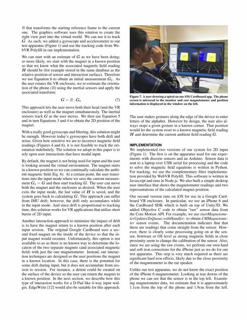
Figure 7. A user drawing a spiral on our iOS Cardboard app. The phonescreen is mirrored to the monitor and raw magnetometer and positioninformation is displayed in the window on the left.
The user makes gestures along the edge of the device to enterletters of the alphabet. However by design, the user also al-ways stops a given gesture in a known corner. That positionwould let the system reset to a known magnetic field readingH and determine the current ambient field reading G.
IMPLEMENTATIONWe implemented two versions of our system for 2D input(Figure 1). The first is on the apparatus used for our exper-iments with discrete sensors and an Arduino. Sensor data issent to a laptop over USB serial for processing and the codeto solve the magnetic field equations is written in Python.For tracking, we use the complementary filter implementa-tion provided by WebVR Polyfill. This software is written inJavascript and runs in Node.js. We also built a simple desktopuser interface that shows the magnetometer readings and tworepresentations of the calculated magnet position.
Our second version runs on iOS for use in a Google Card-board VR enclosure. In particular, we use an iPhone 6 andthe Cardboard SDK which is built on top of Unity3D. Weadded Objective C code to obtain “raw” sensor data fromthe Core Motion API. For example, we use startMagnetome-terUpdatesToQueue:withHandler: to obtain CMMagnetome-ter sensor events. The documentation indicates that thatthese are readings that come straight from the sensor. How-ever, there is clearly some processing going on at the sen-sor, firmware or OS level as strong magnetic fields in closeproximity seem to change the calibration of the sensor. Also,since we are using the raw events, we perform our own hardand soft iron corrections for the iPhone just as we do for ourtest apparatus. This step is very much required as there aresignificant hard iron effects, likely due to the close proximityof the magnetometer to the ear speaker.
Unlike our test apparatus, we do not know the exact positionof the iPhone 6 magnetometer. Looking at tear downs of thephone we can see that the sensor is in the top left. Examin-ing magnetometer data, we estimate that it is approximately1.1cm from the top of the phone and 1.9cm from the left.

Figure 8. Examples of using the $P gesture recognizer to input a rectangle (top) and the D-Pad widget to input “up” (bottom).
Since the magnetometer is so close to the edge, we can seefrom Figure 3 that our permanent magnet would likely sat-urate the sensor if the top of the phone is placed on the endof our VR enclosure used for input. Our preliminary testingindicated this is indeed the situation and therefore we use thereverse configuration. Our estimated distance from the sen-sor to the interaction surface has x = 12.3cm. Also, since thesensor and magnet are far apart and we have no direct controlof sensitivity, we use a much stronger magnet than we usedin our test apparatus where K is approximately 44000. Weactually use two magnets forming a sandwich similar to theoriginal Google Cardboard [10]. One magnet is on the out-side and manipulated by the user. The second magnet is onthe inside and moves with the first. It holds the magnet on theoutside in place when the user lets go. Finally, we noticed alot of sensor noise in our readings at this distance. We applyan exponential moving average to the magnetometer data forsmoothing out the noise.
We developed a demonstration user interface for the iPhonethat is written in C# for Unity3D. Currently, our software tocalculate the position of the magnet from the magnetic fieldreadings, and to estimate device rotations, has not been portedto native code and instead we perform an RPC over the net-work to the same software that runs our test apparatus. Afully native solution is left as future work and should greatlyimprove overall latency in the system.
Interaction WidgetsWe created three different interaction widgets for ourUnity3D Cardboard app. Each is a plane positioned in the 3Dworld. To enter the input mode, the user places the “gaze”cursor on the widget by rotating Cardboard. After two sec-onds, the system switches modes which is visually indicatedby changing the color of the surface. At this point, the systemstarts tracking device rotation to estimate G and also calcu-lates the 2D position of the magnet which is used by the userinterface. When the gaze cursor leaves the widget, the systemreturns to tracking only mode.
Our first widget is a simple drawing surface that paints a pointfor each position that is calculated. Figure 7 shows a noviceuser drawing a spiral with our system. Our second widget per-forms gesture recognition. In particular, we use a Unity3Dport3 of the $P gesture recognizer [11]. For debugging, werender the individual points as they are calculated. Once theuser exits the widget, the recognizer processes the points anddisplays the result of gesture recognition (Figure 8, top). Ourfinal widget is similar to a simple 4-way D-pad (Figure 8, bot-tom). The user activates the widget, moves the magnet in anyof the 4 cardinal positions, then returns it to the center. Thedirection detected is displayed onscreen. This widget is anexample of an interaction that does not have the cumulativeerror of tracking the magnet from input session to input ses-sion. It assumes the user starts with the magnet in the centerof the input area and finishes in the same position.
We had a volunteer from our organization use our system.She had no prior experience with VR enclosures such asGoogle Cardboard and was a novice at using our device (lessthan 30 minutes of experience in total). Figures 7, 8 and ourVideo Figure show examples of her using our system with ourthree different interaction widgets.
DISCUSSION AND FUTURE WORKIn using magnetic field sensing for 2D input, the ambientmagnetic field can have a significant impact. However, as wedetailed, tracking device orientation using the inertial sensorsallows us to successfully use the magnet for user input. Theversion of our system that runs on the iPhone uses the “raw”sensor values. However, the APIs available do not provide thesame level of access to the sensors as a direct hardware APIwould. Also, mobile phone platforms offer several soft sen-sors that utilize a variety of filtering and sensor fusion algo-rithms to overcome some of the limitations of the sensors orcompensate for known but proprietary factors impacting thesensors. Unfortunately, the existing software makes assump-tions that are not valid with our approach. In particular, the
3https://github.com/DaVikingCode/PDollar-Unity

presence of a large permanent magnet that can move resultsin useless sensor readings from these more advanced APIs. Afuture opportunity would be to create APIs that allow a devel-oper to leverage the processing the phones are doing on thesensor data but that also takes into account the presence ofour relatively large moving magnetic field we use for input.
Another area of future work would be to develop a holisticsystem that tracks all of the unknown variables in our sys-tem. Given the above API issues, our current system uses astandalone tracking system based on a complementary filter.Likewise, our magnetic field equations are over-determinedbut we are ignoring possible errors in solving those equa-tions by just using function minimization. There are alsoconstraints on the magnet movement we are not using (thebounding box of the interaction surface), and the current sys-tem does not model the dynamics of user movement for eitherthe VR enclosure or the magnet. It would seem that there isopportunity in combining all of these constraints into one sys-tem that tracks the needed variables.
It would be useful to characterize the overall performance ofthe input system. However, since our method uses the inertialsensors to track device orientation and has modal input, onewould need to simulate realistic device rotation as well inputdurations to get a sense of real world performance. The find-ings would also likely be sensitive to the exact sensors andtracking implementations used. An alternative would be toperform tests with users. However, this approach confoundssystem performance and user performance.
Because our iPhone configuration has the sensor placed rela-tively far away from the interaction surface, we use a strongpair of magnets to create a sufficiently large signal. As such,it can be a bit difficult to slide the magnet over the surface dueto the force exerted between the magnets. Applying a coat-ing with a lower coefficient of friction or developing a handlefor the magnet might provide for easier input. The handlecould both reduce friction between the magnet and the card-board surface, as well as provide a better point for graspingthe magnet with the fingers allowing for easier actuation.
Finally, we developed some simple interaction widgets todemonstrate the capability of our system to provide 2D in-put. In future work, it would be interesting to explore interac-tions where the position of the magnet at the start or end of amovement is known. Doing so would minimize any cumula-tive tracking error similar to our D-Pad example or adaptingEdgeWrite as mentioned above. There are other options toinvestigate for switching between tracking and input modesbeyond using Cardboard’s gaze pointer. Likewise, there isopportunity to create or adapt existing VR interaction tech-niques to make use of our continuous 2D pointing capability.
CONCLUSIONVirtual Reality enclosures provide a cheap and simple way toexperience VR content. However, given that cost and sim-plicity is such a driving factor in their design, there are lim-ited opportunities for input. We extend the original idea fromGoogle Cardboard of using a magnet for input. However in-stead of treating it as binary, we use magnetic field sensing
to provide continuous 2D input. By tracking the orientationof the ambient magnetic field using the inertial sensors in thephone, we can successfully calculate the 2D position of themagnet. We showed our system working on a smartphone andcreated a Unity3D Cardboard app to explore different inter-actions that are enabled with our new 2D pointing capability.
REFERENCES1. Ashbrook, D., Baudisch, P., and White, S. Nenya:
Subtle and Eyes-free Mobile Input with a Magnetically-tracked Finger Ring. In Proceedings CHI ’11 (2011),2043–2046.
2. Chen, K.-Y., Lyons, K., White, S., and Patel, S. uTrack:3D Input Using Two Magnetic Sensors. In Proceedingsof UIST ’13 (2013), 237–244.
3. Chen, K.-Y., Patel, S., and Keller, S. Finexus: TrackingPrecise Motions of Multiple Fingertips Using MagneticSensing . In Proceedings of CHI ’16 (2016), 1504–1514.
4. Chulliat, A., Macmillan, S., Alken, P., Beggan, C., Nair,M., Hamilton, B., Woods, A., Ridley, V., Maus, S., andThomson, A. The US/UK World Magnetic Model for2015-2020. Tech. rep., NOAA National GeophysicalData Center, 2015.
5. Han, X., Seki, H., and Hikizu, M. Wearable HandwritingInput Device Using Magnetic Field. In SICE, 2007Annual Conference, IEEE (2007), 365–368.
6. Han, X., Seki, H., Kamiya, Y., and Hikizu, M. WearableHandwriting Input Device Using Magnetic Field: 2ndReport: Influence of Misalignment of Magnet andWriting Plane. Precision Engineering 34, 3 (2010),425–430.
7. Harrison, C., and Hudson, S. E. Abracadabra: Wireless,High-precision, and Unpowered Finger Input for VerySmall Mobile Devices. In Proceedings of UIST ’09(2009), 121–124.
8. Kraichman, M. B. Handbook of ElectromagneticPropagation in Conducting Media. Headquarters NavalMaterial Command, 1970.
9. Liang, R.-H., Cheng, K.-Y., Su, C.-H., Weng, C.-T.,Chen, B.-Y., and Yang, D.-N. GaussSense: AttachableStylus Sensing Using Magnetic Sensor Grid. InProceedings of UIST ’12 (2012), 319–326.
10. Smus, B., and Riederer, C. Magnetic Input for MobileVirtual Reality. In Proc. of ISWC ’15 (2015), 43–44.
11. Vatavu, R.-D., Anthony, L., and Wobbrock, J. O.Gestures As Point Clouds: A $P Recognizer for UserInterface Prototypes. In Proceedings of ICMI ’12(2012), 273–280.
12. Wobbrock, J. O., Myers, B. A., and Kembel, J. A.EdgeWrite: A Stylus-based Text Entry MethodDesigned for High Accuracy and Stability of Motion. InProceedings of UIST ’03 (2003), 61–70.
13. Yoon, S. H., Huo, K., and Ramani, K. TMotion:Embedded 3D Mobile Input Using Magnetic SensingTechnique. In Adjunct Proc. of UIST ’15 (2015), 71–72.