2g training optimization
DESCRIPTION
2G Training OptimizationTRANSCRIPT

1 © Nokia Siemens Networks
BSS Optimisation WorkshopDenpasar BaliOct 21-25, 2013
NSN – TSEL

2 © Nokia Siemens Networks
Idle Parameter Optimization
Power Control Parameter
Handover Control parameter
Radio Resource Administration
Radio resource Management
KPI case
Measurement processing

3 © Nokia Siemens Networks
Radio Resource Administration

4 © Nokia Siemens Networks
TDMA frame= 8 timeslots( 0.577ms * 8 = 4.615 ms)
01
34
5
76
01
23
45
76
01
23
45
200 kHz
Physical channel e.g. allocated to onesubscriber with FR voiceand no frequency hopping
frequency
time
TDMA frame2
2 2 2
Basic TDMA Structure

5 © Nokia Siemens Networks
Base StationSubsystem
Logical Channelsfor transport of specific content
Physical Channelstransport medium
MS
mapping
Physical channel parametersARFCNTime slot numberFrequency hopping algorithm
GSM Channel Organization

6 © Nokia Siemens Networks
SCH
FCCH
PCH
BCCH
AGCH
RACH
SDCCH
SACCH
FACCH
Stand alone Dedicated Control Channel
Frequency Correction Channel
Synchronisation Channel
Broadcast Control Channel
Paging Channel
Slow Associated Control Channel
Fast Associated Control Channel
Paging Channel
Random Access Channel
Access Grant Channel
BCH
CCCH
DCCH
TCH
DL
DL
DL
UL
CommonChannels
DedicatedChannels
UL/DL
UL/DL
CBCH Cell Broadcast Channel
Logical Channels
FR/HR Full rate / Halft rate TCH
EFR Enhanced Full rate TCH
AMR FR/HR Adaptive multirate TCH (FR/HR)
7 © Nokia Siemens Networks
f s ff s f s
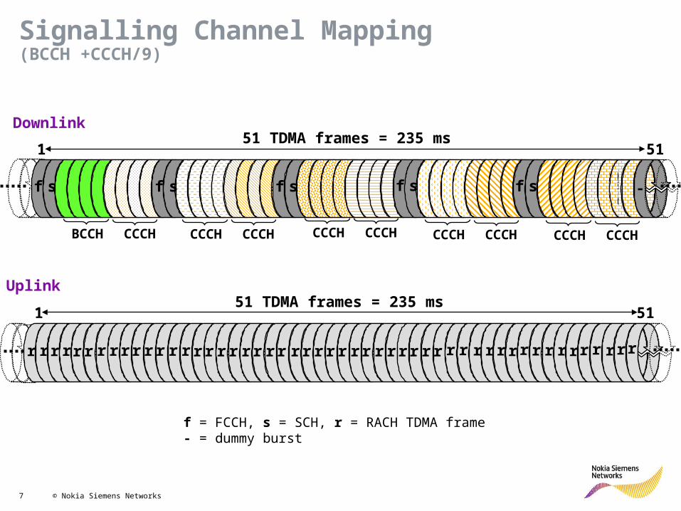
Downlink51 TDMA frames = 235 ms
-
Uplink
BCCH CCCH
f s f s
CCCH CCCH
r r f r r rr r r r fr r r r r rr r r r fr r r r rr f r r
1 51
CCCH CCCH CCCH CCCH CCCH CCCH
r rr r rr r r r r r r rr r r r r rr rr r r
f = FCCH, s = SCH, r = RACH TDMA frame- = dummy burst
51 TDMA frames = 235 ms
1 51
Signalling Channel Mapping(BCCH +CCCH/9)

8 © Nokia Siemens Networks
f s ff s f s
Downlink51 TDMA frames = 235 ms
-
Uplink
BCCH CCCH
f s f s
CCCH CCCHSDCCH 0
SDCCH 1SDCCH 2
SDCCH 3SACCH
0/2 SACCH1/3
r r f r r rr r r r fr r r r r rr r r r fr r r r rr f r r
1 51
SACCH2/0 SACCH
3/1
SDCCH 0SDCCH 1SDCCH 3
SDCCH 2
f = FCCH, s = SCH, r = RACH TDMA frame- = dummy burst
51 TDMA frames = 235 ms
1 51
Signalling Channel Mapping(BCCH + SDCCH/4 + SACCH/C4)

9 © Nokia Siemens Networks
...
26 TDMA frames = 120 ms
1 26
t t tt t t t ft tt t t tt t t tt ft t t ttts i
Full Rate Traffic Channel Configuration (UL & DL)
Half Rate Traffic Channel Configuration (UL & DL)
26 TDMA frames = 120 ms
1 26
t
T T
t t
T
tf
t t
T T T T
t t
T
t
Tf
T
t
T
tt
T
s
S
t = full rate TCH, s = SACCH/T, i = idle TDMA frame
t = half rate TCH, s = SACCH/T (first user)T = half rate TCH, S = SACCH/T (second user) TDMA frame
Traffic Channel Mapping

10 © Nokia Siemens Networks
f
f
i = idle TDMA frame
f
51 TDMA frames = 235 ms
iii
iii
SDCCH 0SDCCH 1
SDCCH 2SDCCH 3
SDCCH 4SDCCH 5
SDCCH 6SDCCH 7
SDCCH 1SDCCH 2
SDCCH 3SDCCH 4
SDCCH 5SDCCH 6
SDCCH 7SDCCH 0
Downlink
Uplink
SACCH0/4 SACCH
1/5
SACCH2/6 SACCH
3/7
SACCH6/2 SACCH
7/3
SACCH4/0SACCH
5/1
51 TDMA frames = 235 ms
1 51
1 51
Signalling Channel Mapping(SDCCH/8 +SACCH/C4)

11 © Nokia Siemens Networks
Signalling Channel Mapping
New improved CCCH features in RG10•BSS20738 CS Paging Coordination in NMO II•BSS21538 Extended CCCH
– Extended CCCH can be allocated to timeslot 2,4,6
•BSS101411 Extended BCCH– For example Uncombined BCCH

12 © Nokia Siemens Networks
Channel configuration defined by parameter channelType
TCHF (0) = full rate traffic channelTCHH (1) = half rate traffic channelTCHD (2) = dual rate traffic channelSDCCH (3) = standalone (SDCCH/8)MBCCH (4) = broadcast control channelMBCCHC (5) = BCCH + SDCCH/4MBCCB (7) = BCCH + SDCCH/3 with CBCHSDCCB (8) = SDCCH/7 with CBCHNOTUSED (9) = timeslot has no radio definition or Abis allocationERACH (10) = random access channel of extended areaEGTCH (14) = EGPRS packed data traffic channel for extended areaLRTCH (15) = long reach traffic channel
Channel MappingParameter Setting
Note: • Some values not allowed in certain tsl (e.g. TSL0 can’t have value 8)• PBCCH is not supported in S13 and onwards
MO Class TR/RTSLParameter channelxType (CHx) where x = 0…7
13 © Nokia Siemens Networks
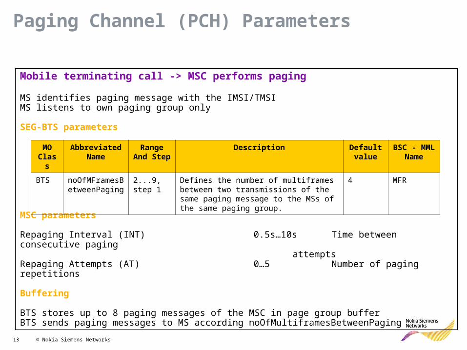
Mobile terminating call -> MSC performs paging
MS identifies paging message with the IMSI/TMSIMS listens to own paging group only
SEG-BTS parameters
MSC parameters
Repaging Interval (INT) 0.5s…10s Time between consecutive pagingattempts
Repaging Attempts (AT) 0…5 Number of paging repetitions
Buffering
BTS stores up to 8 paging messages of the MSC in page group bufferBTS sends paging messages to MS according noOfMultiframesBetweenPaging
Paging Channel (PCH) Parameters
MO Class
Abbreviated Name
Range And Step
Description Default value
BSC - MML Name
BTS noOfMFramesBetweenPaging
2...9, step 1
Defines the number of multiframes between two transmissions of the same paging message to the MSs of the same paging group.
4 MFR

14 © Nokia Siemens Networks
Mobile sends channel requests to BTS separated by random time intervals in case of no answer!
Parameters
Random time interval between consecutive retransmissions
t = S + random [0,.. numberOfSlotsSpreadTrans – 1] RACH slots
S depends on numberOfSlotsSpreadTranssignalling channel mapping (CCCH + SDCCH combined or not in one multi frame)
numberOfSlotsSpreadTrans = 10
signalling channel mapping = not combined S = 58
Therefore t = 58..to..67 RACH slotstime channel requests
RACH Parameters
MO Class
Abbreviated Name
Range And Step Description Default value
BSC - MML Name
BTS maxNumberRetransmission
1,2,4,7 Maximum number of retransmissions on the RACH that the MS can perform.
4 RET
BTS nbrOfSlotsSpreadTrans
MML Range: 3..12, 14, 16, 20, 25, 32, 50
The number of TDMA frames over which retransmission is spread on the RACH (random access channel)
10 SLO

15 © Nokia Siemens Networks
Network gives the MS dedicated resources
Downlink CCCH blocks
• PCH can be used for AGCH messages• AGCH cannot be used for PCH messages
Reservation of CCCH blocks for AGCH
noOfBlocksForAccessGrant (AG) 0..7 possible number, if CCCH and SDCCH are not combined1..7 possible number, if CBCH is used in non combined configuration0..2 possible number, if CCCH and SDCCH are combined
Preference of AGCH messages on PCH
noOfBlocksForAccessGrant 0 PCH can be used only, if no paging messages have to be send
= 0 AGCH messages have higher priority than PCH ones
Number of paging groups
N = (number of CCCH blocks – noOfBlocksForAccessGrant) * noOfMultiframesBetweenPaging
AGCH Parameters

16 © Nokia Siemens Networks
Combined CCCH / SDCCH configuration
noOfBlocksForAccessGrant = 1 2 CCCH blocks for PCH
3 MSs paged per paging message 3 pages per block2 blocks per multi frame 3 * 2 = 6 pages per multiframe
Number of pages per hour 3600 s / 0.235 s * 6 = 91915
Avg of 2 pages required per MS 91915 / 2 = 45957 MSs per hour
BTS 3 MS
Paging_Request
BTS 3 MS
Paging_Request
Paging CapacityExample

17 © Nokia Siemens Networks
Cell with 325 subscribers1 call per subscriber once in a hour1 location update (LU) per subscriber once in 2 hours
Duration of call assignment = 4 s 4 s / 3600 s = 1.11 mErl on SDCCH per subscriber325 subscribers 325 * 1.11 mErl = 0.3607 Erl on SDCCH
Reservation time for LU = 5s 5 s / 7200 s = 0.69 mErl on SDCCH per subscriber325 subscribers 0.2242 Erl on SDCCH
Total SDCCH traffic 0.3607 Erl + 0.2242 Erl = 0.5849 ErlBlocking probability = 1% 4 SDCCHs required SDCCH combined with
CCCH can be used (MBCCHC)
SDCCH Signalling CapacityExample with call Establishment & Location Update

18 © Nokia Siemens Networks
Same cell with 325 subscribersAdditional SMS traffic of 1 mErl per subscriber
325 subscribers 325 * 1 mErl = 0.325 Erl on SDCCH
Total SDCCH traffic 0.5849 + 0.325 Erl = 0.9099 ErlBlocking probability = 1% 5 SDCCHs required not combined with
CCCH (MBCCH)
SDCCH Signalling CapacityExample including SMS

19 © Nokia Siemens Networks
Base Station Identity Code BSIC = Network Colour Code NCC + Base Station Colour Code BCC
bsIdentityCode Setting of BSIC
NCC 0..7, distinguishes between PLMNsBCC 0..7, distinguishes between clusters
BSIC + frequency channel unique identity of adjacent cell
f1f2f3
f1
f1
bcc = 1
bcc = 2
bcc = 3
Base Station Identity Code

20 © Nokia Siemens Networks
200 kHz
890 915 935 960
1 2 3 4 124123 1 2 3 4 124123
duplex distance
Absolute radio frequency carrier number ARFCN
uplink direction downlink direction
Example: GSM 900
Defining Frequency carrier number

21 © Nokia Siemens Networks
Frequency to be used by TRX (must be unique within a BTS)
initialFrequency (FREQ) 1…1023 Setting of ARFCNs
GSM 800: 128 .. 251 GSM 900: 1..124 and 975..1023, 0 GSM 1800: 512..885 GSM 1900: 512..810
f1f2
f3f4
f5f6
f7
f1f2
f3f4
f5f6
f7
f1f2
f3f4
f5f6
f7
Frequency Reuse

22 © Nokia Siemens Networks
Frequency
Time
F1
F2
F3
Call is transmitted through several frequencies to• average the interference (interference diversity)• minimise the impact of fading (frequency diversity)
Frequency hopping techniques
hoppingMode (HOP) BB,RF,NBB = base band hopping (1)RF = RF hopping (2)N = no frequency hopping at all (0)
Principle of Frequency Hopping

23 © Nokia Siemens Networks
Baseband Hopping
TRX 1
TRX 2
TRX 3
0 1 72 Timeslot
TRX 4
BCCH
f 1
f 2
f 3
f 4
HSN1 (BB hopping group 1 and RF hopping)Timeslot 0 hops over TRXs 2-4 onlyBCCH does not hop
HSN2 (BB hopping group 2)Timeslots 1-7 hop over all TRXs
TRXs do not hopPhysical channels moved from one TRX to another
Hopping sequencehoppingSequenceNumber (HSN) 0..63
0 = cyclic hopping1..63 = pseudorandom hopping
Base Band Hopping

24 © Nokia Siemens Networks
RF HoppingStandard technique
TRX 1
TRX 2
TRX 3
0 1 72 Timeslot
TRX 4
BCCH f1 – no hopping
f2,f3..fn – hopping accordingmobile allocation list One hopping sequencenumber only
All TRXs hop except TRX1 (provides BCCH)Up to 63 frequencies available defined by mobile allocation list -> better hopping gain
mobileAllocationList Setting of ARFCN values usedMobileAllocation (MAL) 0,1...2000 0 = BTS detached from any list
1..2000 = indicates list which shall be used

25 © Nokia Siemens Networks
Standard technique
9 hopping hopping frequencies MAI = 0..8But 3 frequencies available for every TRX only
Freeform hopping
For every sector samemobile allocation listhopping sequence numberframe number (frame synchronization)
For every sector differentstarting points for hopping sequencepossible by mobile allocation index offset
maioOffset (MO) 0..62
setting of MAIO
9 hopping hopping frequencies MAI = 0..89 frequencies available for every TRX
RF HoppingFreeform Hopping
MAIO Offset MAI
TRX-1 (BCCH) -
TRX-2 0
TRX-3 1
TRX-4 2
TRX-5 (BCCH) -
TRX-6 3
TRX-7 4
TRX-8 5
TRX-9 (BCCH) -
TRX-10 6
TRX-11 7
TRX-12 8
Sector-3 6
Sector-1 0
Sector-2 3

26 © Nokia Siemens Networks
Freeform hopping
• Not adequate for MA list with consecutive ARFCN values• Avoids co-channel interference but not adjacent channel interference
Flexible MAIO management
MAIO increases with constant step size from one TRX to the next one
maioStep (MS) 1..62
maioOffset = 0, 6, 12 for sector 1, 2, 3maioStep = 218 frequencies required (2 * number of hopping TRXs)
RF HoppingFlexible MAIO Management
MAIO Offset
MAIO Step MAI
TRX-1 (BCCH) -
TRX-2 0
TRX-3 2
TRX-4 4
TRX-5 (BCCH) -
TRX-6 6
TRX-7 8
TRX-8 10
TRX-9 (BCCH) -
TRX-10 12
TRX-11 14
TRX-12 16
Sector-3 2
0
6
12
Sector-1 2
Sector-2 2

27 © Nokia Siemens Networks
BCCH
Band allocation:
MA listConsecutive ARFCN
Only BCCH frequency planning required
Flexible MAIO managementMAIO Offset + MAIO Step
BCCH
Band allocation:
MA listNon-adjacent ARFCN
Freeform hoppingMAIO Offset
MA list and BCCH frequency planning required
RF Hopping (Tight Frequency Reuse)

28 © Nokia Siemens Networks
Changing Frequency Plan
BSIC / TSCFrequenciesFrequency hopping settingIntelligent underlay overlay TRX settings
• Plan downloaded to BSC/BTSs via MML or GUI• File-based plan provisioning• Immediate Plan activation method

29 © Nokia Siemens Networks
Idle Mode Operation

30 © Nokia Siemens Networks
• When the MS is switched ON• When there is no dedicated connection
When?
• To camp on the best suitable cell
Why?
• For MS to receive system info from the NW on DL• For MS to be able to initiate a call whenever needed• For the NW to be able to locate the MS when there is a MT call/SMS
Why to camp on a specific cell?
• PLMN selection• Cell selection & re-selection• Location updates
Idle Mode Tasks
Idle Mode OperationI
MS switched ON
Search RF channels to find BCCH carrier
Check that the PLMN & cell is allowed
MS camps on the best
suitable cell
See slide 10 for detail

31 © Nokia Siemens Networks
Value
LAI (locationAreaId)
• NCC (Network Colour Code) 0 … 7• BCC (BTS Colour Code) 0 … 7
BSIC (bsIdentityCode)
CI (cell-ID 0 … 65535
Parameter
TSC (trainingSequenceCode) 0 … 7
• MCC (Mobile Country Code) 0 … 999• MNC (Mobile Network Code) 0 … 99,
0… 999 (optional 3-digit MNC)• LAC (Location Area Code) 1 … 65533
CGI (Cell Global Identity) MCC + MNC + LAC + CI
ID’s and ID Codes

32 © Nokia Siemens Networks
Campednormally
(adopted from TS 43.022 V5.1.0 chap. 6)
Connectedmode
Normal cell selection
Stored listcell selection
Choose cell Normal
cell re-selection
go here whenever anew PLMN is selected
BA list storedfor PLMN
no BA list storedfor PLMN 1
no suitable cell found
suitable cell foundsuitable cell found
trigger
Suitable cellre-selected
no suitablecell found
suitable cell found
leaveidle
mode
return to idlemode
no suitable cell found
no suitablecell found• IMSI unknown
• Illegal MS• PLMN not allowed
2
2
States and State Transition for Cell Selection

33 © Nokia Siemens Networks
Any cellselection
Camped on
any cell
Choose cell
cell foundno suitable
cell found
suitable cell found
leaveidle
mode
return to idlemode
Connected mode (emergency call
only)
Anycell re-
selection
trigger
cellre-selected
no suitablecell found
go here when no SIM in MS SIM inserted in MS 1
2
cell foundon selected
PLMN
(adopted from TS 43.022 V5.1.0 chap. 6)
States and State Transition for Cell Selection

34 © Nokia Siemens Networks
Normal Cell SelectionSearch all the RF channels, take samples during
3-5 s and calculate averages. And put them in ascending order with respect to signal level.
Then tune to the strongest RF channel.
Search for the frequency correction burst in that carrier in order to verify if it is a BCCH carrier
Camp on the cell
Try to synchronize to the carrier and read the BCCH data
Is it a BCCH carrier?
Is it a correct PLMN ?
Is the cell barred?
Is C1>0
Tune to the next highest RF channel which is not
tried before
No
No
NoNo
Yes
Yes
Yes
Yes

35 © Nokia Siemens Networks
I am outside
I am inside, but have not enough
power
C1 = A – max(B,0)= RLA_C – RXLEV_ACCESS_MIN – max(MS_TXPWR_MAX_CCH – P , 0)
RLA_C = avg received RxLev on BCCHP = MS max output power
max(B,0)
0..63 0..31
Pathloss Criterion C1 for Cell Selection and Reselection

36 © Nokia Siemens Networks
Cell1LAC1
C1 ( Cell1) C1 (Cell2)
A B C
A= 4 dBB= 6 dBC= 8 dB
Cell2LAC2
In case the neighbouring cells belong to different Location Area, a hysteresis is applied with C1 criteria• minimizing ping-pong cell reselections• cellReselectHysteresis (HYS)(BTS) (0…14 dB)
Cell Selection with C1

37 © Nokia Siemens Networks
C1 + CELL_RESELECT_OFFSET – (TEMPORARY OFFSET * H(PENALTY_TIME - T))for PENALTY_TIME 640 s
< C1 if temporary offset big for PENALTY_TIME = 640 sC2 =
serving cell:• C2:
List of 6 strongest carriers:• C2:• C2: • C2:• C2: • C2: • C2:
0 .. 126 dBstep size: 2 dB
0, 10, 20, 30, 40, 50, 60, dB
20 .. 640 sstep size: 20 s
PENALTY_TIME
TEMPORARY OFFSET
CELL_RESELECT_OFFSET
C1
C2
T
new candidate= formerly non-
serving cell
CELL_RESELECT_OFFSET
C1
C2
T
new candidate= former serving cell
no TEMPORARY OFFSET
Pathloss Criterion C2

38 © Nokia Siemens Networks
cell 1
cell 2
cell 3
C2
time5 seconds
cellreselection
5 seconds
CELL_RESELECT_HYSTERESIS (HYS)
LAC = A LAC = B
cell reselection &location update
Cell Reselection Based on Pathloss Criterion C2

39 © Nokia Siemens Networks
Cell "A" Cell "B" Cell "C" Cell "D"
cellReselectOffset 0 dB 20 dB 0 dB 0 dB
temporaryOffset 0 dB 30 dB 0 dB 30 dB
penaltyTime 20 s 20 s 20 s 40 s
Micro 900 "D"Macro 1800 "B"
Macro 900 "A"
Macro 900 "C"Road
Parameters
=30 Cell "A" (Serving Cell)=25 Cell "B"=5 Cell "C"=50 Cell "D"
=30 + 0 (H(x)=0, serving cell) Cell "A"=25 + 20 - 30*H(20 - T) Cell "B"=5 + 0 - 0*H(20 - T) Cell "C"=50 + 0 - 30*H(40 - T) Cell "D"
C1
C2 = C1 + cellReselectOffset - temporaryOffset*H(penaltyTime-T)
C2
Time T: (0 - 19 s)C2 =30 Cell "A"C2 =15 Cell "B"C2 =5 Cell "C"C2 =20 Cell "D"
Time T: (20 - 39 s)C2 =30 Cell "A"C2 =45 Cell "B"C2 =5 Cell "C"C2 =20 Cell "D"
Time T: (> 40 s)C2 =30 Cell "A"C2 =45 Cell "B"C2 =5 Cell "C"C2 =50 Cell "D"
Cell Reselection Based on Pathloss Criterion C2
40 © Nokia Siemens Networks
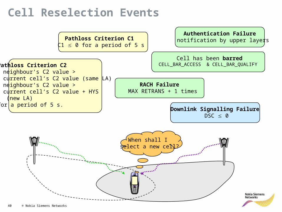
When shall I select a new cell?
Pathloss Criterion C1 C1 0 for a period of 5 s
Pathloss Criterion C2 • neighbour‘s C2 value >
current cell‘s C2 value (same LA)• neighbour‘s C2 value >
current cell‘s C2 value + HYS (new LA)
for a period of 5 s.Downlink Signalling Failure
DSC 0
RACH Failure MAX RETRANS + 1 times
Authentication Failure notification by upper layers
Cell has been barredCELL_BAR_ACCESS & CELL_BAR_QUALIFY
Cell Reselection Events

41 © Nokia Siemens Networks
BTS
BCCH (...,BS_PA_MFRMS,...)
MS
Downlink radio link failure detected!
DSCinit := roundBS_PA_MFRMS
90
paging message successfully
decoded?
DSC 0
DSC := min (DSC+1, DSCinit) DSC := DSC - 4
yes no
no
yesCell
UpdateDSC = Downlink Signalling failure Counter
2..9 multi-frame periods
DSC := DSCinit
DL Signalling Failure

42 © Nokia Siemens Networks
Location Update Procedure
BSS MSC VLR HLR
REQUEST SUBSCRIBER INFO
ALL OK - HLR UPDATE
MS
LOCATION UPDATE REQUEST
SEND SUBSCRIBER ID
REQUEST SUBSCRIBER ID
SEND SUBSCRIBER INFO
AUTHENTICATION
AUTHENTICATION RESPONSE

43 © Nokia Siemens Networks
Paging LocUp
# of cells in Loc. area
signallingtraffic
optimum numberof cells in Loc. area
function of user density,cell size, call arrival rate ...function of
user mobility
Trade-off between Location Update and Paging Traffic
44 © Nokia Siemens Networks
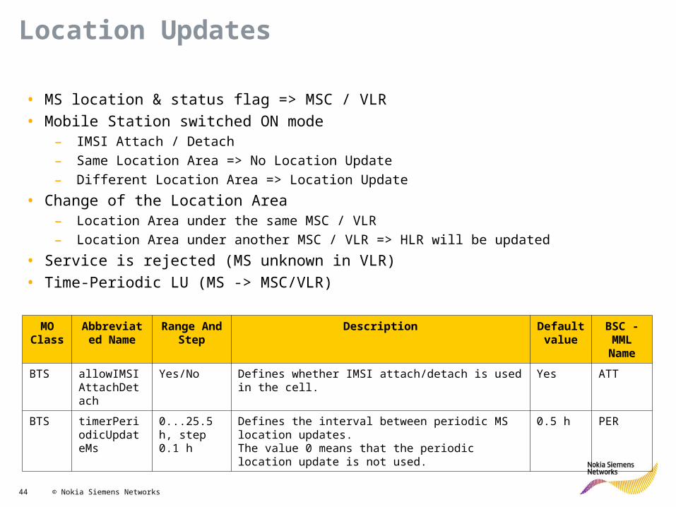
Location Updates
• MS location & status flag => MSC / VLR• Mobile Station switched ON mode
– IMSI Attach / Detach– Same Location Area => No Location Update– Different Location Area => Location Update
• Change of the Location Area– Location Area under the same MSC / VLR– Location Area under another MSC / VLR => HLR will be updated
• Service is rejected (MS unknown in VLR)• Time-Periodic LU (MS -> MSC/VLR)
MO Class
Abbreviated Name
Range And Step
Description Default value
BSC - MML Name
BTS allowIMSIAttachDetach
Yes/No Defines whether IMSI attach/detach is used in the cell. Yes ATT
BTS timerPeriodicUpdateMs
0...25.5 h, step 0.1 h
Defines the interval between periodic MS location updates. The value 0 means that the periodic location update is not used.
0.5 h PER

45 © Nokia Siemens Networks
IDLE MODE OPERATION Idle Mode Controls
Parameter Value
Access Parameters
notAllowedAccessClasses 0 ... 9, 11 ... 15emergencyCallRestricted Yes/No
msTxPwrMaxCCH 13 ... 43 (dBm)rxLevAccessMin -110 ... -47 (dBm)
msMaxDistanceInCallSetup 0 ... 255radiusExtension 0 ... 67 (Km)
cellBarred Yes/Noplmn-permitted 0 ... 7cellReselectHysteresis 0 ... 14 (dB)
Mobility Parameters
cellReselectOffset (REO) 0 ... 126 (dB)
cell reselection parameter index (PI) (N/Y)

46 © Nokia Siemens Networks
IDLE MODE OPERATION Idle Mode Controls definitions • RxLevAccessmin : With this parameter you define the minimum power level an MS has to receive before it is allowed to access the cell. • MsTxPwrMaxCCH : With this parameter you define the maximum transmission power an MS may use when accessing a CCH in the cell.• notAllowedAccessClasses With this parameter you define the MS access classes that are not allowed to access a cell.• Emergency Call Restricted With this parameter you define if an emergency call in the cell is allowed to all MSs or only to the MSs which belong to
one of the classes between 11 to 15. Value ’Y’ means the latter case.• MsMaxDistancein CallSetup With this parameter you define the maximum distance between the BTS and the MS in call setup. The maximum distance
is expressed as an access delay. Within the range of 0...62, one step correlates to a distance of 550 meters. If the access delay of the channel request message exceeds the given maximum, the call attempt is rejected. When the parameter is given a value from 63 to 255, call attempts are never rejected
• radiusExtention With this parameter you define the radius extension of an extended cell

47 © Nokia Siemens Networks
Radio Resource management

48 © Nokia Siemens Networks
Channel request (RACH)MS NETWORK
Immediate assignmentImmediate assignment (AGCH)
Service request (SDCCH)
Service request
Authentication request (SDCCH)
Authentication response (SDCCH) Authentication
Ciphering mode command (SDCCH)
Ciphering mode complete (SDCCH) Ciphering mode setting
Setup (SDCCH)
Call initiationCall proceeding (SDCCH)
Assignment command (SDCCH)
Assignment complete (FACCH) Assignment of traffic channel
Alert (FACCH)
Call confirmation
Connect (FACCH)
Connect acknowledged (FACCH) Call accepted
Signalling (Mobile Originating Call)
Idle parameter
Dedicated parameter

49 © Nokia Siemens Networks
Page request (PCH)MS NETWORK
Immediate assignmentChannel request (RACH)
Page response (SDCCH)
Service request
Authentication request (SDCCH)
Authentication response (SDCCH) Authentication
Ciphering mode command (SDCCH)
Ciphering mode complete (SDCCH) Ciphering mode setting
Setup (SDCCH)
Call initiationCall confirmation (SDCCH)
Assignment command (SDCCH)
Assignment complete (FACCH) Assignment of traffic channel
Alert (FACCH)
Call confirmation
Connect (FACCH)
Connect acknowledged (FACCH) Call accepted
Immediate assignment (AGCH)
Signalling (Mobile Terminating Call)
Idle parameter
Dedicated parameter

50 © Nokia Siemens Networks
DisconnectMS NETWORK
Call clearingRelease
Channel release
Release
Release complete
DisconnectMS NETWORK
Call clearingRelease
Channel release
Release
Release complete
Network initiated
MS initiated
Signalling (Call Release)

51 © Nokia Siemens Networks
MS capabilities
Channel rate : full, half, dual, multi rateSpeech codecs : normal FR, normal HR, EFR, AMR FR, AMR HR, doubleHR(OSC)
MSC demands
A interface circuit allocated for call
BTS demands
Speech codec capabilitiesTCH configurationCurrent resourcesHomogeneous use of TRXs and radio time slotsLarge free groups of radio time slots for high loaded HSCSD BTS
Standard TCH Allocation (General Criteria)
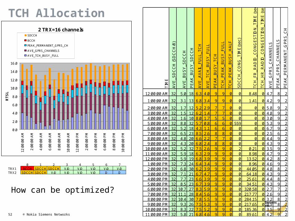
52 © Nokia Siemens Networks
TCH Allocation 2 TRX=16 channels
0.0
2.0
4.0
6.0
8.0
10.0
12.0
14.0
16.0
12:0
0:00
AM
2:00
:00
AM
4:00
:00
AM
6:00
:00
AM
8:00
:00
AM
10:0
0:00
AM
12:0
0:00
PM
2:00
:00
PM
4:00
:00
PM
6:00
:00
PM
8:00
:00
PM
10:0
0:00
PM
RTSL
SDCCH
BCCH
PEAK_PERMANENT_GPRS_CH
AVE_GPRS_CHANNELS
AVE_TCH_BUSY_FULL
0 1 2 3 4 5 6 7TRX1 BCCH SDCCH SDCCH V/D V/D V/D V/D V/DTRX2 SDCCH SDCCH V/D V/D V/D V/D D D
TIM
E
AV
E_S
DC
CH
(SD
CC
H/8
)
AV
E_B
US
Y_S
DC
CH
PE
AK
_BU
SY
_SD
CC
H
AV
E_A
VA
IL_F
ULL
_TC
H
AV
E_T
CH
_BU
SY
_FU
LL
PE
AK
_BU
SY
_TC
H
TCH
_PE
AK
_BU
SY
_FU
LL
TCH
_PE
AK
_BU
SY
_HA
LF
SD
CC
H_C
ON
G_T
IME
(sec
)
TCH
_FR
_RA
DIO
_CO
NG
ES
TIO
N_T
IME
(sec
)
TCH
_HR
_RA
DIO
_CO
NG
ES
TIO
N_T
IME
(sec
)
AV
E_G
PR
S_C
HA
NN
ELS
PE
AK
_GP
RS
_CH
AN
NE
LS
PE
AK
_PE
RM
AN
EN
T_G
PR
S_C
H
12:00:00 AM 32 5.0 18 6.3 4.0 9 9 0 0 8.48 0 4.7 8 2
1:00:00 AM 32 3.1 13 6.8 3.4 9 9 0 0 1.41 0 4.2 9 2
2:00:00 AM 32 1.7 12 5.2 2.9 7 7 0 0 0 0 5.8 9 23:00:00 AM 32 1.5 12 6.2 1.4 7 7 0 0 0 0 4.8 9 24:00:00 AM 32 1.6 10 8.0 1.7 5 5 0 0 0 0 3.0 9 25:00:00 AM 32 8.8 32 5.7 0.8 6 6 0 559 0 0 5.3 9 26:00:00 AM 32 5.2 18 4.3 1.1 6 6 0 0 0 0 6.7 9 27:00:00 AM 32 6.5 23 8.5 2.6 8 8 0 0 0 0 2.5 6 28:00:00 AM 32 4.8 20 6.6 2.2 7 7 0 0 0 0 4.4 9 29:00:00 AM 32 4.3 20 6.8 2.4 8 8 0 0 0 0 4.3 9 2
10:00:00 AM 32 5.2 32 7.5 2.6 9 9 0 2 0.21 0 3.5 9 211:00:00 AM 32 5.9 18 6.3 2.9 9 9 0 0 8.98 0 4.7 9 212:00:00 PM 32 5.9 19 6.8 3.9 9 9 0 0 13.52 0 4.2 8 2
1:00:00 PM 32 7.3 24 6.4 3.4 9 9 0 0 8.96 0 4.6 9 22:00:00 PM 32 6.8 30 6.2 3.9 9 9 0 0 44.05 0 4.8 8 23:00:00 PM 32 7.1 21 6.7 4.7 9 9 0 0 64.18 0 4.3 9 24:00:00 PM 32 7.7 23 6.6 3.9 9 9 0 0 25.61 0 4.4 8 25:00:00 PM 32 8.5 23 6.7 3.9 9 9 0 0 34.51 0 4.3 9 26:00:00 PM 32 10.7 27 8.3 5.9 9 9 0 0 320.58 0 2.7 7 27:00:00 PM 32 11.1 28 8.4 5.6 9 9 0 0 217.77 0 2.6 9 28:00:00 PM 32 10.4 30 7.8 5.5 9 9 0 0 284.15 0 3.2 8 29:00:00 PM 32 9.3 26 7.5 5.3 9 9 0 0 217.65 0 3.5 8 2
10:00:00 PM 32 8.3 22 7.5 5.2 9 9 0 0 185.36 0 3.5 9 211:00:00 PM 32 5.8 21 6.8 4.6 9 9 0 0 89.61 0 4.2 9 2
How can be optimized?

53 © Nokia Siemens Networks
Channel allocation ( For each TS)
Each TRX – have its own Quality both DL and UL and TRX with bad quality (UL and DL) will result bad KPI on respective TRX
Placing each Time Slot (BCCH, SDCCH, TCH and PDTCH) properly will result good KPI (SDSR, DCR, HOSR TBF Completion rate)
Shitting SDCCH, BCCH can improve SDSR and DCR

54 © Nokia Siemens Networks
Measurement of uplink receive level on idle channels = uplink interference
Averaging over interferenceAveragingProcessAverPeriod (AP) = 1..32 SACCH periods
Classification into interference bands based on interferenceAveragingProcess (BO1..BO4) = -110..-47 dBm
BSC tries to allocate TCH from best interference band (can be requested by MSC) If not available, BSC tries to take TCH from next band
0 71 2 3 4 5 6
rxLevUL = -75 dBm BO5 –47 (fixed)
BO0 –110 (fixed)
BO4 -90BO3 -95
BO1 -105BO2 -100
Standard TCH Allocation(Interference Bands)

55 © Nokia Siemens Networks
Priority for TCH from BCCH TRX
BCCH transmitted permanently -> no additional interference in networkPlanned to be least interfered channels
Priority for TCH from other TRX
BCCH TRX does not hop in case of RF hopping -> hopping gain only for other TRX
Parameter
trxPriorityInTCHAlloc (TRP) 0 = no priority1 = priority for BCCH TRX2 = priority for other TRX3 = priority for BCCH TRX for non-AMR users, priority for other TRX for AMR users
Prioritized TCH Allocation (TRP)Whole band , 50 channels 1 ch=200kHz
BCCH, 30 channels TCH, 20 channels
All 50 channels for BCCH and TCH
Case1
Case2

56 © Nokia Siemens Networks
Enables to differentiate Rx level requirement for:• MS camping to the network /RxLev Access Min• MS accessing to TCH /RX level based TCH access
RX level based TCH allocation method• RX Level measured by the MS is used to determine whether the BTS is
acceptable for TCH allocation• TCH allocation for emergency calls is not restricted due to low RX level
Provides better drop call meters and better performance of MSs• MSs having too low Rx levels are not allowed to camp the networkBy separating camping and TCH access thresholds the operator will be able to provide the maximum camping footprint
RX level based TCH Allocation (RXP)
Note! RG20 feature – Energy optimized TCH allocation

57 © Nokia Siemens Networks
Allows to define minimum C/N ratios separately for each call type (AMR FR, AMR HR, EFR/FR, HR and 14.4 data)Parameter values ‘RX level based TCH access’:
0: RX level based TCH access is not used (C/N definitions not in use)1: RX level based TCH access is used in call setup2: RX level based TCH access is used in call setup and in handovers
Downlink RX Level
-> TCH Access
Soft blocking C/N FR: 0…63dB/ def: 12dB
Soft Blocking C/N HR: 0…63dB/ def: 14dB
Soft blocking C/N AMR FR: 0…63dB/ def: 7dB
Soft blocking C/N AMR HR: 0…63dB/ def: 12dB
Soft blocking C/N 14.4 : 0…63dB/ def: 14dB
RX level based TCH Allocation (RXTA)

58 © Nokia Siemens Networks
Priorities
No TCH available for call set up / handover -> request put into queueDifferent kinds of requests can have different priorities
queuePriorityUsed (QPU) Y/N enables use of priorities
queueingPriorityCall (QPC) 1..14 priority for call set up requestqueuePriorityNonUrgentHo (QPN) 1..14 priority for non urgent handover (power budget,
umbrella, slow moving MS, traffic reason)request
queueingPriorityHandover (QPH) 1..14 priority for urgent handover (all other) request
Queue length and time
maxQueueLength (MQL) 0..100% percentage of number of TCHs handled by BTS timeLimitCall (TLC) 0..15 s time a call set up request is kept in the queue
0 = queuing is disabledtimeLimitHandover (TLH) 0..10 s time a handover request is kept in the queue
0 = queuing is disabled
Queuing (Parameters)

59 © Nokia Siemens Networks
Conditions
Timers set to values > 0User of priorities enabledQueue not full with requests of equal or higher priority than the current one
Queuing of call set up requests
Reservation of SDCCH resources-> SDCCH easily overbooked-> blocking of services like SMS or location update
Queuing (Entering the Queue)

60 © Nokia Siemens Networks
Handover request queued by target BTS
Handover timers hoPeriodPBGT and hoPeriodUmbrella stopped Measurement processing and averaging continues as usual
Intra BSC handover Inter BSC handover
Queuing possibility checked for all possible target cells Order according conventional ranking
Target BTS given by MSC by handover request message
Queuing (Handover)

61 © Nokia Siemens Networks
With TCH allocation
Release of busy TCH Check of queue from top to bottom for best matching request If TCH allocation possible, request removed from queue
Without TCH allocation
Queuing timer expiresRequest of higher priority enters full queue
Queuing (Leaving the Queue)

62 © Nokia Siemens Networks
Directed Retry Timer maxTimeLimitDirectedRetry expires
call cleared, even if still in queue
Queuing timer expires
target cell evaluation continues, if directed retry timer is still running
Queuing (Together with Directed Retry)

63 © Nokia Siemens Networks
BTS does not receive measurement report on SACCH for running call for the first time
Counter initialised with value of radioLinkTimeout (4,8,..64 SACCH periods)
SACCH not received again
Counter decremented by 1
SACCH received again
Counter incremented by 2 (but not beyond initial value)
Counter has value 0
Call release due to radio link time out
Example: short tunnel
Dropped Call ControlRadio Link Timeout

64 © Nokia Siemens Networks
• RLT is based on SACCH deletion but SACCH is though not using a dynamic codec like voice in AMR, which means:
• Using the EFR RLT value an AMR customer can have the call dropped because RLT = 0 when still the FER is good
• RLT is not anymore reliable with the same value in AMR than in EFR• Due to the fact that the FER performance is different when comparing AMR
calls to EFR calls, the Radio Link Timeout need to be defined separately for AMR
• The Radio Link Timeout parameters for AMR are ARLT and AHRLT. The principle of these is the same than in the RLT but it is used only for the AMR capable mobile stations. ARLT & AHRLT are not supported in Talk Family base stations.
Dropped Call ControlRadio Link Timeout
65 © Nokia Siemens Networks
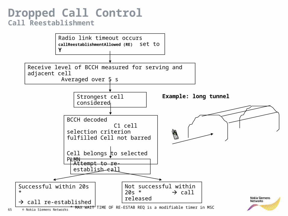
Radio link timeout occurs callReestablishmentAllowed (RE) set to Y
Receive level of BCCH measured for serving and adjacent cell Averaged over 5 s
Strongest cell considered
BCCH decoded C1 cell selection criterion fulfilled Cell not barred
Cell belongs to selected PLMN
Attempt to re-establish call
Successful within 20s *
call re-established
Not successful within 20s * call released
Example: long tunnel
Dropped Call ControlCall Reestablishment
* MAX WAIT TIME OF RE-ESTAB REQ is a modifiable timer in MSC

66 © Nokia Siemens Networks
NPT parameter related (Idle Parameter)

67 © Nokia Siemens Networks
Measurement Processing

68 © Nokia Siemens Networks
MeasurementReport
Standard
• Rx level• Rx quality• Level & BSIC of up to 6 neighbours• 3G cells
Enhanced
Standard + following:• DL frame erasure rate• DTX bit error probability• Real time difference serving – adjacent cell• 3G cells• Control over reporting priority
Measurements
Idle mode
• MS listens to BCCH
Dedicated mode
• MS sends DL measurement report on SACCH• BTS performs UL measurements
Introduction

69 © Nokia Siemens Networks
MeasurementReport
Standard
• Rx level• Rx quality• Level & BSIC of up to 6 neighbours• 3G cells
Enhanced
Standard + following:• DL frame erasure rate• DTX bit error probability• Real time difference serving – adjacent cell• 3G cells• Control over reporting priority
Measurements
Idle mode
• MS listens to BCCH
Dedicated mode
• MS sends DL measurement report on SACCH• BTS performs UL measurements
Introduction

70 © Nokia Siemens Networks
P (dBm) P (dBm) LEVNo offset 10 dB offset
-110 -100 0-109 -99 1-108 -98 2 . . . . . . . . .-49 -39 61-48 -38 62-47 -37 63
Activation of offset to code high levelsscaleOrd (SCO)(SEG)(0,1,2)(0)
0 = no offset used1 = offset used in general 2 = MS decides automatically about offset
Coding of Rx Level

71 © Nokia Siemens Networks
BER (%) BER (%) QUAL
RANGE MEAN< 0.2 0.14 00.2-0.4 0.28 10.4-0.8 0.57 20.8-1.6 1.13 31.6-3.2 2.26 43.2-6.4 4.53 56.4-12.8 9.05 6> 12.8 18.1 7
Coding of Rx Quality
Average window = 4Quality samples 0,0,7,0WRONG!!: (0+0+7+0)/4 = 1.75 (wrong!!)RIGHT: (0.14+0.14.+18.1+0.14)/4 = 4.63 (right!!) => corresponds to Qual5

72 © Nokia Siemens Networks
BEP BER (%) QUAL
VALUE RANGE22..31 < 0.2 019..21 0.2-0.4 116..18 0.4-0.8 213..15 0.8-1.6 310..12 1.6-3.2 4 7..9 3.2-6.3 5 4..6 6.3-12.6 6 0..3 > 12.6 7
Mapping of BEP to RX Quality

73 © Nokia Siemens Networks
X axis: frame erasure rate (< 1%, 1-5 %, 5-10 %, 10-15 %, > 15 %)Y axis: RX quality (0..7)Z axis: Percentage of measurements for each FER category
Frame Erasure Rate for Handover / Power Control DecisionfepInPcHoUse (FPHO)(BSC)(Y,N)(N)
Mapping of FER to RX Quality
74 © Nokia Siemens Networks
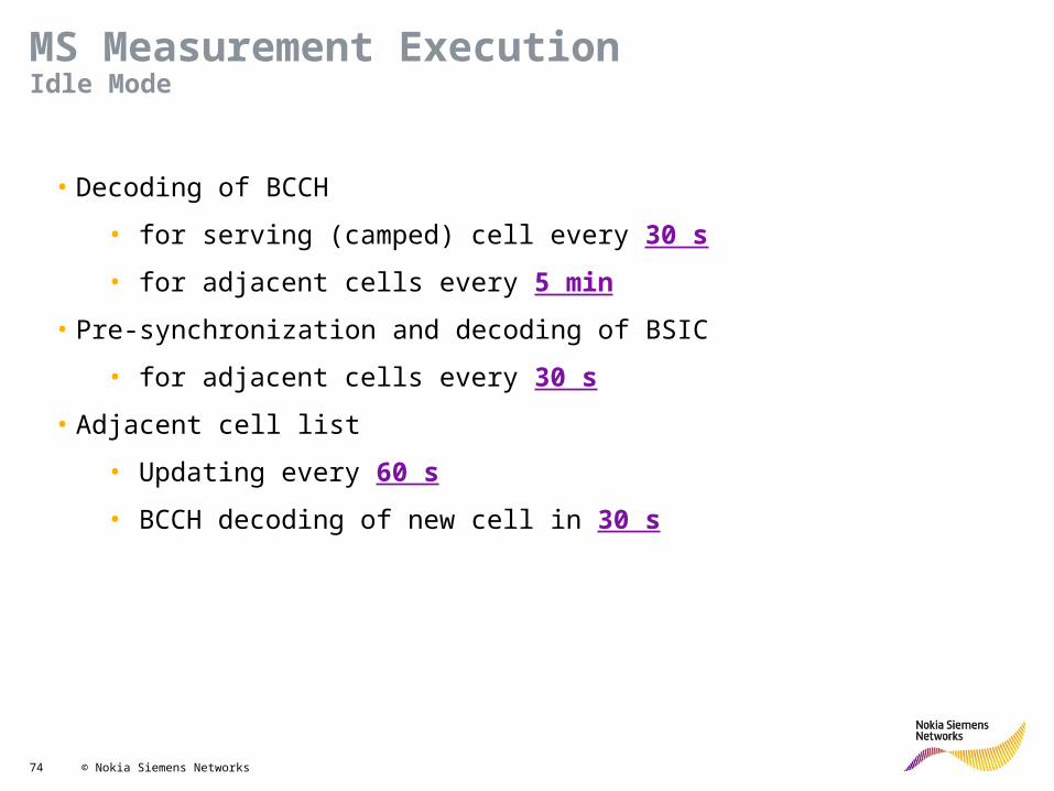
• Decoding of BCCH
• for serving (camped) cell every 30 s• for adjacent cells every 5 min
• Pre-synchronization and decoding of BSIC
• for adjacent cells every 30 s• Adjacent cell list
• Updating every 60 s• BCCH decoding of new cell in 30 s
MS Measurement ExecutionIdle Mode

75 © Nokia Siemens Networks
• Measures RX level and quality for serving cell
• Detects whether DTX is used
26 FRAME MULTIFRAME = 120 ms
TDMA FRAMES
TCH SACCH IDLE
• Measures frequencies of adjacent cells
• BSIC decoding for at least one adjacent cell
• Pre-synchronization on SCH
TDMA FRAMES 4.615 ms
SACCH PERIOD = 480 ms
RX TX RX TX RX TXMEAS MEASMEAS
MS Measurement ExecutionDedicated Mode I

76 © Nokia Siemens Networks
Power Control

77 © Nokia Siemens Networks
• Longer service time of battery• Realization of power class• Supported by default on UL
Reduced interference on DL/UL
Activation of DL power control
powerCtrlEnabled (PENA) Y,N
Power control independent
• for DL and UL• for each call
Power Control Motivation

78 © Nokia Siemens Networks
30 dB Range
Power classdependentrange
Attenuations
Power Values
Maximum MS output power
msTxPwrMaxGSM (PMAX1) 5..39 dBm GSM 900 TCHmsTxPwrMaxGSM1x00 0..36/32,33 dBm GSM 1800/1900 TCH (PMAX2)msTxPwrMaxCCH (TXP1) 5..39 dBm GSM 900 CCHmsTxPwrMaxCCH1x00 0..30 dBm GSM 1800 CCH(TXP2) 0..32 dBm GSM 1900 CCH
Minimum MS output power
minMSTxPower (PMIN) 5..39 dBm GSM 9000..36 dBm GSM 18000..32 dBm GSM 1900
Maximum BTS output power (by minimum attenuation)
bsTxPwrMax (PMAX1) 0..30 dB GSM 900bsTxPwrMax1x00 (PMAX2) 0..30 dB GSM 1800/1900
Minimum MS output power (by maximum attenuation)
bsTxPowerMin 0..30 dB
Power Control ParameterOutput Power Limits

79 © Nokia Siemens Networks
Fixed increment step size
• pcIncrStepSize (INC) 2,4,6 dB
Fixed decrement step size
• pcRedStepSize (RED) 2,4,6 dB
Desired power level can be achieved in 1 or 2 commands
Yes
Fixed step size
No
Variable step size
Power Control ParametersPower Change Step Sizes

80 © Nokia Siemens Networks
UL Level
UL Quality <Av_RXQUAL_UL>
<Av_RXLEV_UL>
DL Level
DL Quality <Av_RXQUAL_DL>
<Av_RXLEV_DL>
POWER CONTROLUPLINK
THRESHOLD COMPARISON
POWER CONTROLDOWNLINK
Power control interval
powerCtrlInterval (INT) 0..31 s
Power Control StrategyMeasurement Averaging

81 © Nokia Siemens Networks
threshold
Actual average samples
Nx samplesLess than Px samples exceed thresholdNo power change triggered
Nx samplesPx samples are equal to or exceed thresholdPower change triggeredSignal level thresholds
pcUpperThresholdLevelDL/UL (UDR/UUR) -110..-47 dBmpcLowerThresholdLevelDL/UL (LDR/LUR) -110..-47 dBm
Signal quality thresholds
pcUpperThresholdQualDL/UL (UDR/UUR) 0..7pcLowerThresholdQualDL/UL (LDR/LUR) 0..7
Number of average samples (for each threshold)
Nx 1..32Px 1..32
Power change step size estimation
Power Control StrategyTriggering

82 © Nokia Siemens Networks
Exceeded threshold Action Reason
pcUpperThresholdLevelDL BTS power decrease Signal levelpcLowerThresholdLevelDL BTS power increase Signal levelpcUpperThresholdLevelUL MS power decrease Signal levelpcLowerThresholdLevelUL MS power increase Signal level
pcUpperThresholdQualDL BTS power decrease Signal qualitypcLowerThresholdQualDL BTS power increase Signal qualitypcUpperThresholdQualUL MS power decrease Signal qualitypcLowerThresholdQualUL MS power increase Signal quality
Power Control StrategyScenarios

83 © Nokia Siemens Networks
AMR Power Control
Exceeded threshold Action ReasonAMR Power Control FR PC Lower Threshold DL Rx Qual
BTS power increase Poor DL signal quality
AMR Power Control FR PC Lower Threshold UL Rx Qual
MS power increase Poor UL signal quality
AMR Power Control FR PC Upper Threshold DL Rx Qual
BTS power decrease Good DL signal quality
AMR Power Control FR PC Upper Threshold UL Rx Qual
MS power decrease Good UL signal quality
AMR Power Control HR PC Lower Threshold DL Rx Qual
BTS power increase Poor DL signal quality
AMR Power Control HR PC Lower Threshold UL Rx Qual
MS power increase Poor UL signal quality
AMR Power Control HR PC Upper Threshold DL Rx Qual
BTS power decrease Good DL signal quality
AMR Power Control HR PC Upper Threshold UL Rx Qual
MS power decrease Good UL signal quality
AMR FR
AMR HR
Details in chapter on AMR

84 © Nokia Siemens Networks
POC
Quality
Signal level
Increasedue to bad Signal level
DecreaseDue to goodSignal level
Increase due to Bad quality
Decrease due to good quality
Qual 0
Qual 7
-110 dB-47 dB
LowerLevel
UpperLevel
UpperQuality
LowerQuality
No action
Ping pong effect

85 © Nokia Siemens Networks
POC
Quality
Signal level
Increasedue to level
DecreaseDue to level
Increase due to quality
Decrease due to quality
Qual 0
Qual 7
-110 dB-47 dB
LowerLevel
UpperLevel
UpperQuality
LowerQuality
6dB
No action

86 © Nokia Siemens Networks
POC and HOC (UL)
Quality
Signal levelQual 0
Qual 7
-110 dB-47 dB
UL Level HOThreshold
No action
UL Quality HOThreshold
When UL quality HO is triggered• Should MS be sent full power?•What about UL level

87 © Nokia Siemens Networks
Power Control Summary
Lower Level Upper Level
Upper Quality
Lower Quality
No actionPower decreasedue to level
Power increasedue to quality
Power increasedue to levelor quality
Power increasedue to quality
Power decreasedue to levelor quality
Power increasedue to level
Power decreasedue to quality6 dB
Power increasedue to level
Qual 0
Qual 7
-110 dBm -47 dBm

88 © Nokia Siemens Networks
pcLowerThresholdsLevelDL/UL
Power control triggeredUL: Power increase of MSDL: Power increase of BTS
RXLEV_DL/UL > pcLowerThresholdLevelDL/UL - 2 powerIncrStepSize
Yes
Fixed step size
PWR_INCR_STEP = powerIncrStepSize
No
Variable step size
PWR_INCR_STEP = pcLowerThresholdLevelDL/UL – RXLEV_UL/DL
Actual receive level RXLEV_DL/UL
Power Increase Due to Signal LevelFor MS & BTS

89 © Nokia Siemens Networks
pcUpperThresholdsLevelDL
Power control triggeredPower decrease
Yes
Fixed step size
PWR_DECR_STEP = powerDecrStepSize
No
Variable step size
PWR_DECR_STEP = Min (RXLEV_DL – pcUpperThresholdLevelDL, 10)
Actual received level RXLEV_DL
RXLEV_DL < pcUpperThresholdLevelDL + 2 powerDecrStepSize OR
variableDLStepUse (VDLS) = No
Power Decrease Due to Signal LevelFor BTS

90 © Nokia Siemens Networks
pcUpperThresholdsLevelUL
Power control triggeredPower decrease
Yes
Fixed step size
PWR_DECR_STEP = powerDecrStepSize
No
Variable step size
PWR_DECR_STEP = RXLEV_UL – pcUpperThresholdLevelUL
Actual received level RXLEV_UL
RXLEV_UL < pcUpperThresholdLevelUL + 2 powerDecrStepSize
Power Decrease Due to Signal LevelFor MS

91 © Nokia Siemens Networks
pcLowerThresholdsQualDL/UL
Power control triggeredUL: Power increase of MSDL: Power increase of BTS
Actual receive quality RXQUAL_DL/UL
Variable step size based on actual quality
PWR_INCR_STEP = (1 + Max (0,QUAL)) * powerIncrStepSize
QUAL = RXQUAL_DL/UL – pcLowerThresholdQualDL/UL
Step size based on actual level
Take algorithm for power increase due to signal level
Take largest step size
Power Increase Due to Signal QualityFor MS & BTS

92 © Nokia Siemens Networks
pcUpperThresholdsQualDL/UL
Power control triggered
Actual received quality RXQUAL_DL/UL
Actual RXLEV_DL/UL – pcLowerThresholdLevelDL/UL < 6 dB
Yes No
No power decrease
Avoid ping pong effect
Power decrease
Take algorithm for power decrease due to signal level(different for MS & BTS power decrease)
Power Decrease Due to Signal QualityFor MS & BTS with No Power Optimization

93 © Nokia Siemens Networks
NPT parameter related (POC Parameter)
Should be greater than HOC

94 © Nokia Siemens Networks
Handover Control

95 © Nokia Siemens Networks
Intra cellOnly other carrier / timeslot
Inter cellIntra BSC
Inter BSCIntra MSC
Inter MSC
Inter PLMNGlobal Cell ID requiredMCC + MNC + LAC + CI
Germany Czech Republic
Intra PLMNSimple Cell ID requiredLAC + CI
Handover Types

96 © Nokia Siemens Networks
Multi Layer Network Types
Coverage Layer: Gives access to the networkCapacity Layer: Provides additional capacity and allows traffic distribution
Macro cells
Micro cells Intelligent Underlay OverlayDifferent frequencies for high / low power TRx
Normalfrequency
Super reusefrequency
GSM 900 cellGSM 1800 cell

97 © Nokia Siemens Networks
threshold
Actual average samples
Nx samplesLess than Px samples >= thresholdNo handover triggered
Nx samplesPx samples are >= thresholdhandover triggered
Signal interference thresholdshoThresholdsInterferenceDL/UL (IDR/IUR) -110..-47 dBm
Signal quality thresholdshoThresholdsQualDL/UL (QDR/QUR) 0..7
Signal level thresholdshoThresholdLevelDL/UL (LDR/LUR) -110..-47 dBmhoThresholdRapidLevelUL (RPD) -110..-47 dBm
MS speed thresholdsupper/lowerSpeedLimit (USL/LSL) 0..255 (unit = 2km/h)
Number of average samplesNx 1..32Px 1..32
Target cell selection
Handover StrategyTriggering
Trigger Point – When the set threshold has been met or exceeded Px times of Nx times

98 © Nokia Siemens Networks
More than one handover criterion fulfilled -> process of higher priority performedHandover and power control criteria fulfilled -> handover performed
1) Interference (uplink or downlink)2) Intra-segment inter-band because of downlink level (from higher to lower frequency band) 3) Uplink quality4) Downlink quality5) AMR unpacking (uplink level and also uplink unpacking quality triggers)6) Uplink level7) AMR unpacking (downlink level and also downlink unpacking quality triggers)8) Downlink level9) Coverage based inter-system handover to WCDMA RAN10) IMSI-based inter-system handover to WCDMA RAN11) IMSI-based handover12) DTM-based handover to WCDMA RAN13) Inter-system handover to WCDMA RAN14) MS-BS distance (maximum or minimum)15) Turn-around-corner MS16) Rapid field drop17) Slow/fast-moving MS18) Umbrella19) Power budget20) DTM-based handover to a GSM DTM cell21) BSC-initiated TRHO22) IUO23) Intra-segment HO based on load24) AMR packing because of good uplink and downlink quality25) AMR unpacking because of bad uplink or downlink quality26) PC because of lower quality thresholds (uplink and downlink)27) PC because of lower level thresholds (uplink and downlink) 28) PC because of upper quality thresholds (uplink and downlink)29) PC because of upper level thresholds (uplink and downlink)
Handover Strategy(Priorities)
Exercise:Whu UL has many times higher priority than DL?

99 © Nokia Siemens Networks
HO due to UL/DL QualityIF
AV_RXQUAL_DL_HO >=HoThresholdsQualDL
THENHandover cause Downlink quality
IFAV_RXQUAL_UL_HO >=
HoThresholdsQualULTHEN
Handover cause Uplink quality
Target cells is listed based on below criteria1. AV_RXLEV_NCELL(n) > RxLevMinCell(n) + MAX(0,Pa)
2.AND IFEnableHoMarginLevQual(n)= Yes
THENAV_RXLEV_NCELL(n) > AV_RXLEV_DL_HO + (BsTxPwrMax - BS_TXPWR)
+ HoMarginQual(n)3. ELSE
PBGT(n) > HoMarginPBGT(n) (2)
Order of preference of target cellsPRIORITY(n) = HoPriorityLevel(n) - HoLoadFactor(n)
HoLoadFactor value is taken into account when BTSLoadThreshold is exceeded.
Interval between handovers and handover attempts
Listing set of target cell
Priority of target cell
Timer of source cell

100 © Nokia Siemens Networks
HO due to UL/DL LEVELIF
AV_RXLEV_DL_HO<=HoThresholdsLevDL
THENHandover cause Downlink level
IFAV_RXLEV_UL_HO<=HoThresholdsLevUL
THENHandover cause Uplink level
Target cells is listed based on below criteria1. AV_RXLEV_NCELL(n) > RxLevMinCell(n) + MAX(0,Pa)
2.AND IFEnableHoMarginLevQual(n)= Yes
THENAV_RXLEV_NCELL(n) > AV_RXLEV_DL_HO + (BsTxPwrMax - BS_TXPWR)
+ HoMarginLev(n) 3. ELSE
PBGT(n) > HoMarginPBGT(n) (2)
Order of preference of target cellsPRIORITY(n) = HoPriorityLevel(n) - HoLoadFactor(n)
HoLoadFactor value is taken into account when BTSLoadThreshold is exceeded.
GUARD_TIME = 2 * HoPeriodPBGT (Ho Due PBGT)GUARD_TIME = 2 * HoPeriodUmbrella (HO Due to Umbrella)
Listing set of target cell
Priority of target cell
Timer of source cell

101 © Nokia Siemens Networks
HO due to Fast/Slow moving MSMS speed in relation to cell size:
IFMsSpeedDetectionState= 0
AdjCellLayer(n) = LowerFastMovingThreshold(n)> 0
Measured MS speed:IF
AV_MS_SPEED <= LowerSpeedLimitTHEN
MS is slow-movingIF
AV_MS_SPEED >= UpperSpeedLimitTHEN
MS is fast-moving
AV_RXLEV_NCELL(n) > RxLevMinCell(n) + MAX (0, Pa)
THENRXLEV_CNT(n) = RXLEV_CNT(n) + 2
ELSERXLEV_CNT(n) = RXLEV_CNT(n) - 1
IFRXLEV_CNT(n) >=
FastMovingThreshold(n)THEN
Handover cause Slow-moving MS
Target cell evaluation:AdjCellLayer(n) = Lower/Upper
ANDAV_RXLEV_NCELL(n) > HoLevelUmbrella(n) (1')
Handover to low layer cell is not possible if maximum power capability of MS exceeds gsm/dcsMicrocellThreshold
IFMsSpeedDetectionState= 0
THENHandover Cause Fast/Slow-moving MS
ELSEScale averaging parameters

102 © Nokia Siemens Networks
HO due to Fast/Slow moving MS (Count)Target cell evaluation:
AdjCellLayer(n) = Lower/UpperAND
AV_RXLEV_NCELL(n) > HoLevelUmbrella(n) (1')Handover to low layer cell is not possible if maximum power capability of MS exceeds
gsm/dcsMicrocellThreshold
Order of preference of target cellsPRIORITY(n) = HoPriorityLevel(n) - HoLoadFactor(n)
HoLoadFactor value is taken into account whenBTSLoadThreshold is exceeded
Interval between handovers and handover attempts

103 © Nokia Siemens Networks
HO due to Umbrella
IFEnableUmbrellaHO= Yes
HoPeriodUmbrella - interval between the umbrellahandover threshold comparisons
Umbrella handover and target cell evaluation:AV_RXLEV_NCELL(n) > HoLevelUmbrella(n) (1')
AND( [(P >= macro_thr) AND (pwr(n) >= macro_thr)]
OR[(P <= micro_thr) AND (pwr(n) <= micro_thr)]
OR[(P < macro_thr) AND (pwr(n) < macro_thr) AND
(P > micro_thr) AND (pwr(n) > micro_thr)] )
Interval between handovers and handover attempts
Order of preference of target cellsPRIORITY (n) = HoPriorityLevel(n) - HoLoadFactor(n)
HoLoadFactor value is taken into account whenBTSLoadThreshold is exceeded.

104 © Nokia Siemens Networks
Umbrella handover to 1800 cell
A
B
900 ‘Macro’
hoLevelUmbrella = -85 dBmgsmMacrocellThreshold = 33 dBmdcsMacrocellThreshold = 33 dBm
Threshold RX level handover –95 dBm
Threshold umbrella handover –85 dBm
PTCH (msTxPwrMax(n)) = 30 dBm -> micro cellPMAX = 30 dBm -> handover to micro cell onlyhoThresholdLevelDL = -95 dBm
1800 ‘Micro’
RX level handoverback to 900 cell
Umbrella +FMT HandoverExample
After FMT>1 (example)

105 © Nokia Siemens Networks
HO due to PBGT
IFEnablePowerBudgetHO= Yes
HoPeriodPBGT - interval between the power budgetthreshold comparisons
Power budget and target cell evaluation:AV_RXLEV_NCELL(n) > RxLevMinCell(n) + MAX(0, Pa) (1)
ANDPBGT(n) > HoMarginPBGT(n) (2)
PBGT(n) = (B - AV_RXLEV_DL_HO -(BsTxPwrMax - BS_TXPWR)) - (A - AV_RXLEV_NCELL(n))
Interval between handovers and handover attempts
Order of preference of target cellsPRIORITY (n) = HoPriorityLevel(n) - HoLoadFactor(n)
HoLoadFactor value is taken into account whenBTSLoadThreshold is exceeded.
106 © Nokia Siemens Networks
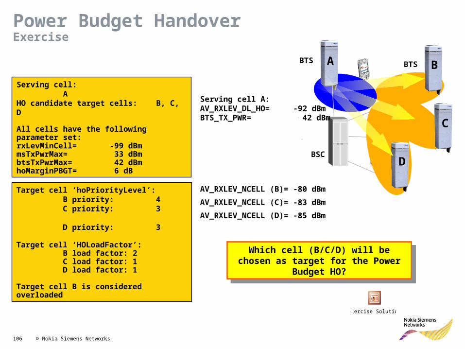
Serving cell: AHO candidate target cells: B, C, D
All cells have the following parameter set:rxLevMinCell= -99 dBmmsTxPwrMax= 33 dBmbtsTxPwrMax= 42 dBmhoMarginPBGT= 6 dB
Target cell ‘hoPriorityLevel’:B priority: 4C priority: 3 D priority: 3
Target cell ‘HOLoadFactor’:B load factor: 2C load factor: 1D load factor: 1
Target cell B is considered overloaded
BTS BTS
BTS
BTSBSC
A B
C
D
Which cell (B/C/D) will be chosen as target for the Power Budget HO?
AV_RXLEV_NCELL (B)= -80 dBmAV_RXLEV_NCELL (C)= -83 dBmAV_RXLEV_NCELL (D)= -85 dBm
Serving cell A:AV_RXLEV_DL_HO= -92 dBmBTS_TX_PWR= 42 dBm
Exercise Solution
Power Budget HandoverExercise

107 © Nokia Siemens Networks
enablePowerBudgetHo = Yes & enableUmbrellaHo = YesPower budget handover to cells of the same layerUmbrella and FMT handover to cells of different layer
Combined Umbrella & Power Budget HOOverview
macrocells
microcells
RR
PBGT,RR
PBGT,RRUMBR+FMT
UMBR umbrella HORR radio reason HOPBGT power budget HO

108 © Nokia Siemens Networks
UPPER layer (macro)
SAME layer (serving layer)
LOWER layer (micro)
Predefinition of layer possible by adjCellLayer (ACL)Three layers visible relative to serving cellUsed for target cell evaluation• Combined umbrella and power budget • Handover based on MS speed• Fast moving MS handling in macro cell
N (no predefinition)
Combined Umbrella & Power Budget HOAdjacent Cell Classification

109 © Nokia Siemens Networks
HO due to Directed RetryIF
DirectedRetryUsed = YesHandover from SDCCH of serving cell to TCH of adjacent cell due to congestion
minTimeLimitDR – Target cell evaluation startedMaxTimeLimitDR - Target cell evaluation stopped
Target Cell evaluationIF
DirectedRetryMethod = 1THEN
AV_RXLEV_NCELL(n) > RxLevMinCell(n) + MAX(0, Pa) (1)AND
AV_RXLEV_NCELL(n) > DRThresholdELSE
AV_RXLEV_NCELL(n) >RxLevMinCell(n) + MAX (0,Pa)
Interval between handovers and handover attempts

110 © Nokia Siemens Networks
No TCH available during call set up in serving cell -> handover to TCH of other cell
Must be enabled withdrInUse (DR) Y/N
Thresholds to be exceeded by target cell according condition (1a)drMethod (DRM) 0/1 Defined type of thresholdrxLevMinCell -110..-47 dBm Used if drMethod = 0drThreshold (DRT) -110..-47 dBm Used if drMethod = 1 and
drThreshold > rxLevMin CellTimers (to be counted from TCH assignment)minTimeLimitDirectedRetry (MIDR) 0..14 s No target cell evaluation
allowedmaxTimeLimitDirectedRetry (MADR) 1..15 s Target cell evaluation allowed
SDCCHTCH
congested TimeAssignmentRequest
minTimeLimitDR
maxTimeLimitDR
DR not allowed DR allowed
Directed RetryParameters

111 © Nokia Siemens Networks
HO due to Rapid Field Drop
IFHoThresholdsRapidLevUL/Px > 0
IFPx number of RXLEV_UL measurement < HoThresholdsRapidLevUL
THENHandover cause Rapid field drop
Target cell evaluationIF
ChainedAdjacentCell(n) = YesAND
AV_RXLEV_NCELL(n) > RxLevMinCell(n) + MAX(0, Pa) (1)
Order of preference of target cells:The target cells are ranked according to radio link properties
(equation 1).

112 © Nokia Siemens Networks
Chained Cell
1st
2nd
Serving cell
hoThresholdRapidLevUL = -93 dBmhoThresholdRapidLevUlN = 2chainedAdjacentCell = Y
Threshold rapid field drophandover –93 dBm
Handover triggered
Serving Cell
Rapid Field Drop HandoverExample

113 © Nokia Siemens Networks
NPT parameter related (HOC Parameter)
Should be lower than POC

114 © Nokia Siemens Networks
NPT parameter related (HOC Parameter)
Should be lower than POC

115 © Nokia Siemens Networks
NPT parameter related (ADCE Parameter)

116 © Nokia Siemens Networks
NPT parameter related (ADCE Parameter)

117 © Nokia Siemens Networks
KPI case

118 © Nokia Siemens Networks
Optimization Principle
service quality
cell coverage cell capacity
Optimizationand Tailoring
Optimization process is a way to do changes in a network so that those network have
maximum on Capacity, Coverage and Quality
Excessive value RxLevAmi will improve KPI but coverage
and quality will reduce
Site with height >40m with total tilt =2 will have wide coverage but KPI will bad
Site with FRL/FRU = 100% will have max capacity but have
lower Quality

119 © Nokia Siemens Networks
KPI- Rules, SDCCH BlockingSDCCH Blocking
>X%
Is dynamic sddch active
Is dynamic sdcch reaching max values
in some moment
Is combined sdcch used
yes
yes
Check unavailability in the cells,
averarage available sdcch
Availability OK
Check sdcch blocking. Can sdcch capacity be added
without tch blocking
SDCCH blocking is high
yes
No
Yes, remove combined sdcch
No, check parameterValues and make
corrections
No, activateDynamic sdcch
Yes, make corrections
Case closedNo
Yes, add sdcch capacity
Add TRX and add Sdcch capacity
sdcch Blocking is still high
No
Yes
Is high sdcch traffic due to Location updates. If yes, can LU area be optimized? Check also PRAU parameter, can the value
be increased?
noYes, Optimize LU
area border
no
ND_211ND_130Cngt_2Blck_5
Blck_5b
ND_139,ND_131ND_130, uav_22
csf_1a,csf_11Ava_45a
ND_211c1154
ND_211c2032
NetAct PlannerP_nbcs_cc_pm
ND_211
If SDCCH block high please check:1.TCH/SDCCH availability2.LOC design (SDCCH traffic profile)3.Parameter (CRO, CRH, RxLevAmi)

120 © Nokia Siemens Networks
KPI- Rules, SDCCH Drop
SD DCR > 2% andSD DCRnum > 10
Drops due to RF Reasons
Drops due to Abis ReasonsNo
Drops due to A-interface Reasons
No Drops due to other ReasonsNo
Case ClosedNo
RF Abis A Other
Yes Yes Yes Yes
Yes
No
ND_166
If SDCCH drop high please check:1.DL/UL Quality2.CRO/CRH, TRP setting3.TA profile – overshooting possibility4.SDCCH TS location

121 © Nokia Siemens Networks
KPI- Rules, SDCCH Drop due to RF/Abis

122 © Nokia Siemens Networks
KPI- Rules, SDCCH Drop due to Aif

123 © Nokia Siemens Networks
KPI- Rules, SDCCH Drop (A)
A>X%
A interface problems. Alarms are checked and A interface trace is
done
Investigate alarms.If problems
are not solved, activate A trace
Any improvements
Any problems found. Trace
was long enough
Make corrections
Check ET lines in the BSC and
transcoders /TCSM. Any problems
Repair ET lines
Still A drops or problems
No
Activate
No
No
Yes
Yes
Alarms Are
Solved
Yes
Trace was not long
enough
Case Closed
Yes
No
Trace was Long enough. Not
An problem was found
Investigate log files. Check DX
causes, see document Call
related DX causes in BSC
No
alarms

124 © Nokia Siemens Networks
KPI- Rules, SDCCH Drop (other)
Other
Lapd fails BTS fails Netw ActFails
User Act, bcsu, resets
Still lots of other drops
Check all the alarms
signalling fails or PCM fails.
Check transmissio / parameters
Yes
No
TRX or BTS fails. Check
that BTS/ TRX are working
properly
Yes
No
Configuration problems,
check configurations
Yes
No
Resets or act fail channel
failures
Yes
No
Case Closed No
Yes
125 © Nokia Siemens Networks
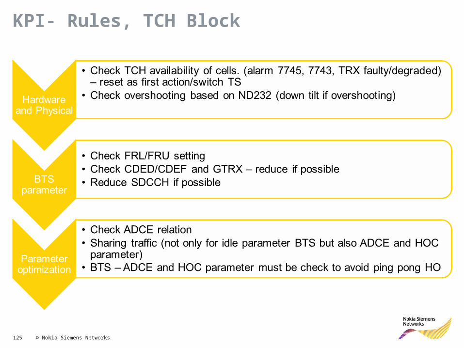
KPI- Rules, TCH Block

126 © Nokia Siemens Networks
TCH SEIZURES FOR NEW CALLtch_norm_seiz /c1009+tch_seiz_due_sdcch_con /c1099 (S5)+msc_i_sdcch_tch /c4044 +bsc_i_sdcch_tch /c4057+cell_sdcch_tch /c4074-tch_succ_seiz_for_dir_acc /c1165 (S7)
-tch_re_est_assign /c57032 (S7)
TCH DROPS AFTER SEIZURETCH_RADIO_FAIL /c1013+TCH_RF_OLD_HO /c1014+TCH_ABIS_FAIL_CALL /c1084+TCH_ABIS_FAIL_OLD /c1085+TCH_A_IF_FAIL_CALL /c1087+TCH_A_IF_FAIL_OLD /c1088+TCH_TR_FAIL /c1029+TCH_TR_FAIL_OLD /c1030+TCH_LAPD_FAIL /c1046+TCH_BTS_FAIL /c1047+TCH_USER_ACT /c1048+TCH_BCSU_RESET /c1049+TCH_NETW_ACT /c1050+TCH_ACT_FAIL_CALL /c1081
-tch_re_est_assign /c57032 (S7)
DROPS
CALLS
100 * %
STARTED CONVERSATIONSconver_started /c57015- msc_i_tch_tch /c4043
CONVERSATION DROPSdropped_calls /c57007
TCH DROPS AFTER ASSIGNMENTtch_new_call_assign /c57033+tch_ho_assign /c57034
-tch_norm_release /c57035-tch_ho_release /c57036
-tch_re_est_assign /c57032
TCH ASSIGNMENTS FOR NEW CALLtch_new_call_assign /c57033
-tch_re_est_assign /c57032
TCH RELEASEDisconnect from MS
RF CHN RELEASERf_channel_release_ack from BTS
CONVERSATION STARTED conn_ack to BTS
TCH ASSIGNED Assignment_complete from BTS
TCH SEIZED BSC allocates a TCH as a response toTCH request (Channel Activation)
Dcr_8hDcr_5a
Dcr_3j
KPI- Rules, TCH Drop Call Ratios

127 © Nokia Siemens Networks
KPI- Rules, TCH Drop due to RF/Abis

128 © Nokia Siemens Networks
KPI- Rules, TCH Drop due to RF Old

129 © Nokia Siemens Networks
How unnecessary HO happened??
GSM
DCS
RxLev = -80dBmCRO=0
RxLev = -95dBmCRO=23HO threshold = 20
On idle mode received level for GSM is -80 dBm while DCS can be (-95 dBm + (2 x 23) -49dBm
On dedicated mode user will move from DCS to GSM due to DCS level already too low
Unecessary HO can lead to DCR due to RF Old and HO fail (ex. Due to GSM blocking)

130 © Nokia Siemens Networks
How unnecessary HO happened??
GSM/DCS A GSM/DCS B
Call establish on cell A, then received level drop below HO threshold. User will move from cell A to cell B
After user serve by cell B, cell B will ask user to do handover as received level on cell B already below HO threshold.
RxLev = -95dBmHO threshold = 20RxLevmin from A to B = 12
RxLev = -92dBmHO threshold = 20RxLevmin from A to B = 12

131 © Nokia Siemens Networks
KPI- Rules, TCH Drop due to Aif

132 © Nokia Siemens Networks
KPI- Rules, TCH Drop due to Transcoder

133 © Nokia Siemens Networks
KPI- Rules, TCH Drop
DCR > X% andDCRnum > XX
Drops due to RF Reasons
Drops due to Abis ReasonsNo
Drops due to A-interface Reasons
NoDrops due to Transcoder Reasons
No Drops due to other ReasonsNo
Case Closed No
RF Abis A TR Other
Yes Yes Yes Yes Yes
Yes
No
ND_163

134 © Nokia Siemens Networks
KPI- Rules, TCH Drop (Other)
Other
Lapd fails BTS fails Netw ActFails
User Act, bcsu, act fails
Still lots of other drops
Check all the alarms
signalling fails or PCM fails.
Check transmissio / parameters
Yes
No
TRX or BTS fails. Check
that BTS/ TRX are working
properly
Yes
No
Configuration problems,
check configurations
Yes
No
Resets or act fail channel
failures
Yes
No
Case Closed No
Yes

135 © Nokia Siemens Networks
KPI- Rules, coverage problems (dlq_2a and ulq_2a)
Here are some examples how different kind of problems can be found
Like Normal distribution HW Problem, TRX/combiner etc is brokenQ0 Q1 Q2 Q3 Q4 Q5 Q6 Q7 Q0 Q1 Q2 Q3 Q4 Q5 Q6 Q7
CL10 10645 8516 6813 5450 4360 3488 2791 2232 CL10 5323 4258 3406 2725 2180 1744 4563 9765CL15 47043 37634 30108 24086 9865 7543 5643 2345 CL15 11761 9409 7527 6022 9383 1886 65432 7675CL20 56204 44963 35971 28776 6574 10324 345 65 CL20 14051 11241 8993 7194 18271 2581 65438 63562CL30 200863 160690 128552 102842 17654 9876 145 28 CL30 33772 27017 21614 17291 75037 2469 18765 14523CL40 12785 10228 8182 6546 456 112 24 23 CL40 3196 2557 2046 1636 4938 28 3659 2648CL63 4583 1123 583 452 261 76 26 2 CL63 1146 281 146 113 3378 19 100 174
HW problem, Q4 amount of samples is strange Interference problemQ0 Q1 Q2 Q3 Q4 Q5 Q6 Q7 Q0 Q1 Q2 Q3 Q4 Q5 Q6 Q7
CL10 5323 4258 3406 2725 2180 1744 1395 1116 CL10 5323 4258 3406 2725 2180 1744 1395 1116CL15 23522 18817 15054 12043 18765 3772 2822 1173 CL15 23522 13234 10588 8470 13234 10588 8470 6776CL20 28102 22482 17985 14388 36542 5162 173 33 CL20 28102 2123 1699 1359 2123 1699 1359 1087CL30 67544 54035 43228 34582 150073 4938 73 14 CL30 67544 3634 2908 2326 3634 2908 2326 1861CL40 6393 5114 4091 3273 9876 56 12 12 CL40 6393 4091 3273 2618 4091 3273 2618 4532CL63 2292 562 292 226 6756 38 13 1 CL63 9987 7543 4323 3454 2275 1187 876 654
HW Problem, TRX/combiner etc is brokenQ0 Q1 Q2 Q3 Q4 Q5 Q6 Q7
CL10 200863 160690 128552 102842 17654 9876 7865 6543CL15 16543 13234 10588 8470 6776 2822 1173 234CL20 2654 2123 1699 1359 1087 173 33 65CL30 4543 3634 2908 2326 1861 73 14 28CL40 5114 4091 3273 2618 2095 12 12 23CL63 24 54 8 87 7 0 0 0
1
2
3
1. Lots of Q4 samples. Distribution is not OK HW problem. Site reset will help2. Lots of bad signal level samples. TRX/Combiner is broken. If no HW problem
Site is totally in wrong place, site is like transferring traffic to another cell ( cause level HO). Typically a HW problem
3. Lots of Q6 and Q7 samples. Distribution is not OK, no Q5 samples HW problems. Site reset or broken TRX
4. Typical normal interference problem.
Here are some examples how different kind of HW problems can be found
4

136 © Nokia Siemens Networks
KPI- Rules, Interference analysis DL /UL
Rx Quality x Rx Level
Coverage Problem:Bad quality and Low Rx Level
Interference Problem:Bad quality and High Rx Level
Good Quality
High Rv Level
HW Problem:Bad Quality for all Rx Levels
NWD report 204 model
HW ProblemAll samples below -100dBmCL10 <-100dBm
Same level – quality distribution for both UL and DL

137 © Nokia Siemens Networks
KPI- Rules, Interference, UL
q0 q1 q2 q3 q4 q5 q6 q7-100dBm 10645 8516 6813 5450 4360 3488 2791 2232-95dBm 47043 37634 30108 24086 9865 7543 5643 2345-90dBm 56204 44963 35971 28776 16574 5676 845 65-80dBm 200863 160690 128552 102842 17654 3653 145 28-70dBm 1234 987 790 632 505 404 323 259-47dBm 24 19 15 12 10 8 6 5
MS power control can be seen here. If Power is reduced → no bad UL problems. BSC border is increasing good level samples
q0 q1 q2 q3 q4 q5 q6 q7-100dBm 10645 8516 6813 5450 4360 3488 2791 2232-95dBm 47043 37634 30108 24086 9865 7543 5643 2345-90dBm 56204 44963 35971 28776 16574 5676 845 65-80dBm 200863 160690 128552 102842 17654 3653 145 28-70dBm 1234 987 790 632 505 404 323 259-47dBm 24 19 15 12 10 8 6 5
Bad interference problems. By POC parameter interference can be decreased, how power is adjusted etc. Also optimum MS power feature improves UL interference, no full power is sent after HO.
q0 q1 q2 q3 q4 q5 q6 q7-100dBm 10645 8516 6813 5450 4360 3488 2791 2232-95dBm 47043 37634 30108 24086 9865 7543 5643 2345-90dBm 56204 44963 35971 28776 16574 5676 845 65-80dBm 200863 160690 128552 102842 17654 3653 145 28-70dBm 1234 987 790 632 505 404 323 259-47dBm 24 19 15 12 10 8 6 5
Bad quality sample due to signal level problems. Diversity should be checked, also possibilities to use LNA to improve UL signal level. Antenna place should be also checked if there are some obstacles near the antenna.
138 © Nokia Siemens Networks
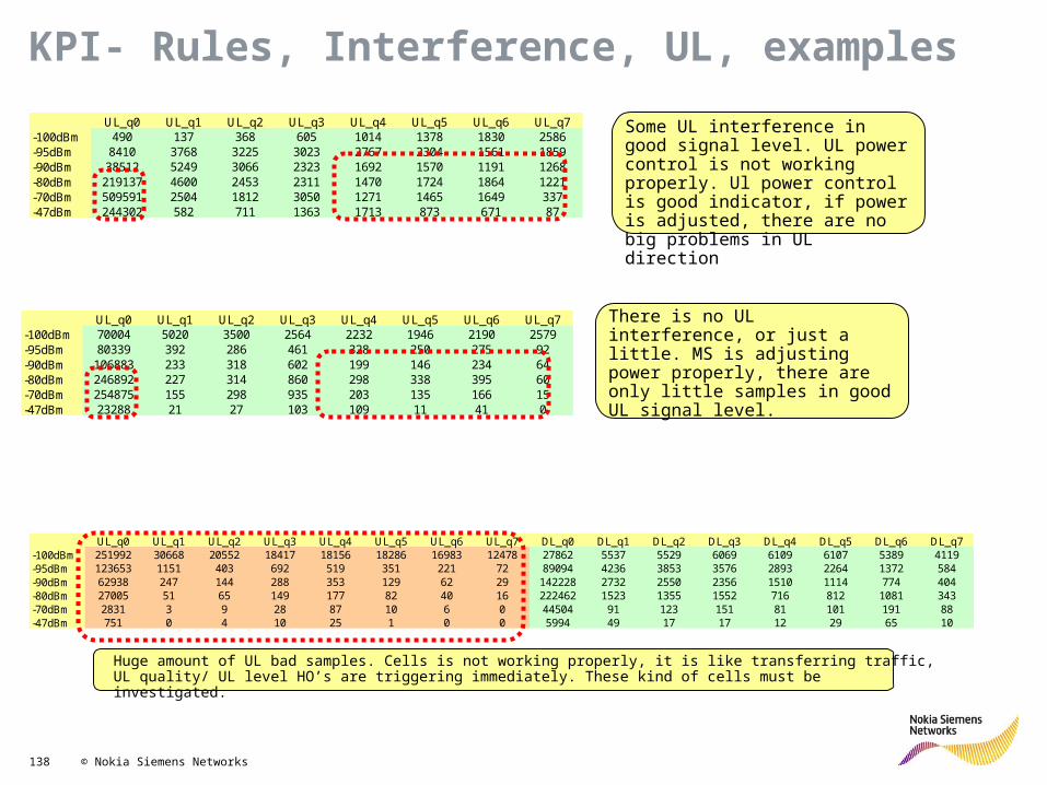
KPI- Rules, Interference, UL, examples
UL_q0 UL_q1 UL_q2 UL_q3 UL_q4 UL_q5 UL_q6 UL_q7 DL_q0 DL_q1 DL_q2 DL_q3 DL_q4 DL_q5 DL_q6 DL_q7-100dBm 251992 30668 20552 18417 18156 18286 16983 12478 27862 5537 5529 6069 6109 6107 5389 4119-95dBm 123653 1151 403 692 519 351 221 72 89094 4236 3853 3576 2893 2264 1372 584-90dBm 62938 247 144 288 353 129 62 29 142228 2732 2550 2356 1510 1114 774 404-80dBm 27005 51 65 149 177 82 40 16 222462 1523 1355 1552 716 812 1081 343-70dBm 2831 3 9 28 87 10 6 0 44504 91 123 151 81 101 191 88-47dBm 751 0 4 10 25 1 0 0 5994 49 17 17 12 29 65 10
Huge amount of UL bad samples. Cells is not working properly, it is like transferring traffic, UL quality/ UL level HO’s are triggering immediately. These kind of cells must be investigated.
UL_q0 UL_q1 UL_q2 UL_q3 UL_q4 UL_q5 UL_q6 UL_q7-100dBm 490 137 368 605 1014 1378 1830 2586-95dBm 8410 3768 3225 3023 2767 2304 1561 1859-90dBm 38512 5249 3066 2323 1692 1570 1191 1268-80dBm 219137 4600 2453 2311 1470 1724 1864 1221-70dBm 509591 2504 1812 3050 1271 1465 1649 337-47dBm 244302 582 711 1363 1713 873 671 87
UL_q0 UL_q1 UL_q2 UL_q3 UL_q4 UL_q5 UL_q6 UL_q7-100dBm 70004 5020 3500 2564 2232 1946 2190 2579-95dBm 80339 392 286 461 328 250 275 92-90dBm 106883 233 318 602 199 146 234 64-80dBm 246892 227 314 860 298 338 395 60-70dBm 254875 155 298 935 203 135 166 15-47dBm 23288 21 27 103 109 11 41 0
Some UL interference in good signal level. UL power control is not working properly. Ul power control is good indicator, if power is adjusted, there are no big problems in UL direction
There is no UL interference, or just a little. MS is adjusting power properly, there are only little samples in good UL signal level.

139 © Nokia Siemens Networks
q0 q1 q2 q3 q4 q5 q6 q7-100dBm 10645 8516 6813 5450 4360 3488 2791 2232-95dBm 47043 37634 30108 24086 9865 7543 5643 2345-90dBm 56204 44963 35971 28776 16574 5676 845 65-80dBm 200863 160690 128552 102842 17654 3653 145 28-70dBm 12785 10228 8182 6546 456 112 24 23-47dBm 4583 1123 583 452 261 76 26 2
KPI- Rules, Interference, DL
Bad interference problem → signal level good (<-80dBm) and sometimes no better cell available. If better cell available and quality samples are 4 or worse → HO (reason quality or interference, depends on the parameter) Interference is causing drops.
Really bad interference problem → signal level is really good (<-70dBm) and usually no better cell available → no HO → samples can be seen in the table. Interference is causing drops.
Situation is “network is working properly” If there are quality 4 or worse samples → quality HO. Most of the samples are q4 samples. If lots of q5..q7 samples → interference problem and interference must be analyzed / removed. If quality HOs but no q5..q7 samples → better cell is available → no interference problems. In these signal levels overlapping exists and if handover reason is no PBGT, it will be quality HO. By parameter amount of quality HOs can be adjusted
q0 q1 q2 q3 q4 q5 q6 q7-100dBm 10645 8516 6813 5450 4360 3488 2791 2232-95dBm 47043 37634 30108 24086 9865 7543 5643 2345-90dBm 56204 44963 35971 28776 16574 5676 845 65-80dBm 200863 160690 128552 102842 17654 3653 145 28-70dBm 12785 10228 8182 6546 456 112 24 23-47dBm 4583 1123 583 452 261 76 26 2
q0 q1 q2 q3 q4 q5 q6 q7-100dBm 10645 8516 6813 5450 4360 3488 2791 2232-95dBm 47043 37634 30108 24086 9865 7543 5643 2345-90dBm 56204 44963 35971 28776 16574 5676 845 65-80dBm 200863 160690 128552 102842 17654 3653 145 28-70dBm 12785 10228 8182 6546 456 112 24 23-47dBm 4583 1123 583 452 261 76 26 2
q0 q1 q2 q3 q4 q5 q6 q7-100dBm 10645 8516 6813 5450 4360 3488 2791 2232-95dBm 47043 37634 30108 24086 9865 7543 5643 2345-90dBm 56204 44963 35971 28776 16574 5676 845 65-80dBm 200863 160690 128552 102842 17654 3653 145 28-70dBm 12785 10228 8182 6546 456 112 24 23-47dBm 4583 1123 583 452 261 76 26 2
Bad quality samples due to signal level problems. If PBGT overlapping is not existing → lots of quality HOs + level HOs (margin are lower than in PBGT). Not interference problem, more signal level problem.
Check how much samples vs. HOs → are better cells available or not.

140 © Nokia Siemens Networks
KPI- Rules, Interference, DL, examples
DL_q0 DL_q1 DL_q2 DL_q3 DL_q4 DL_q5 DL_q6 DL_q7-100dBm 12057 2827 3108 3952 4783 6200 7013 8156-95dBm 44818 4811 5041 5866 6587 7223 7259 6781-90dBm 98587 7107 7400 8334 8470 8781 7825 6162-80dBm 225919 7450 7731 8445 7726 7441 5695 3369-70dBm 88708 1014 971 998 751 688 689 367-47dBm 15881 84 109 122 104 167 199 184
DL_q0 DL_q1 DL_q2 DL_q3 DL_q4 DL_q5 DL_q6 DL_q7-100dBm 8006 1636 1681 2197 2379 2510 2025 1290-95dBm 24951 1636 1627 1767 1037 431 175 53-90dBm 57559 2171 1884 1651 781 330 161 47-80dBm 200602 5771 4686 4130 1736 566 254 97-70dBm 304206 5464 4310 3796 1315 350 153 105-47dBm 108047 2134 1908 1623 689 230 129 64
There are almost as much samples Q5 and Q7 samples as Q 4 samples → even interference is really bad or there is no better cell available ( no ho’s after bad quality samples). These kind of interference cells should be optimized, otherwise there are lots of drops etc
There are no as much Q5…Q7 samples as Q4 samples → after interference samples Quality HO is done or the interference situation is not so bad, for example sampling is Q0,Q2,Q4,Q2,Q5,Q0,Q2,Q3,Q4,Q2 → quality HO is not triggering
DL_q0 DL_q1 DL_q2 DL_q3 DL_q4 DL_q5 DL_q6 DL_q7-100dBm 7055 1398 1374 1906 2163 2003 1468 832-95dBm 20109 1307 1274 1161 694 332 211 84-90dBm 34531 1053 745 587 273 131 94 41-80dBm 107539 875 518 630 161 98 113 47-70dBm 177614 283 316 663 61 32 29 9-47dBm 58718 78 91 198 54 40 54 32
There are bad quality samples only due to signal level problems.

141 © Nokia Siemens Networks
KPI- Rules, Interference (internal / external)
•Internal Interference– Interference can be seen from stats or can be measured by scanner.– Neighbor cells (DL) or mobiles (UL) are causing interference.– By frequency / network planning interference can be decreased.
•External Interference– Interference can be seen from stats or can be measured by scanner.– External radio frequencies are causing interference
Military use In the border area, interference is coming from other country. Some external wireless system (for example some wireless industry system)
is causing interference Increased I level can be also due to external interference

142 © Nokia Siemens Networks
KPI- Rules, HOSR

143 © Nokia Siemens Networks
KPI- Rules, HO fail
sum(msc_o_succ_ho + bsc_o_succ_ho + cell_succ_ho) Total HO success ratio = 100 * (-------------------------------------------------------------------------------- ) (ho_65)
sum(msc_o_ho_cmd + bsc_o_ho_cmd_assgn + bts_ho_assgn)
sum(a.msc_o_succ_ho + a.bsc_o_succ_ho + a.cell_succ_ho + a.msc_to_wcdma_ran_succ_tch_ho)
Total HO failure ratio = 100 * (1- -------------------------------------------------------------------------------------) (hfr_2b) sum(b.msc_o_ho_cmd + b.bsc_o_ho_cmd_assgn +
b.bts_ho_assgn+a.msc_gen_sys_wcdma_ran_ho_com)
/* handovers failing due to blocking */ sum(a.msc_o_fail_lack + a.bsc_o_fail_lack + a.cell_fail_lack
+ a.msc_to_wcdma_ran_fail_lack) HO failure ratio due to RF blocking = 100 * --------------------------------------------------------------------------------------- /* all HO attempts */ sum(b.msc_o_ho_cmd + b.bsc_o_ho_cmd_assgn +
b.bts_ho_assgn + a.msc_gen_sys_wcdma_ran_ho_com)
(hfr_55a)