2h style heavy duty hydraulic cylinders - … cylinder division plant locations – see page ii. b...
TRANSCRIPT

2H STYLE HEAVY DUTY HYDRAULIC CYLINDERS
INDUCTION HARDENED CHROME RODS
AVAILABLE IN STEEL AND STAINLESS STEEL CONSTRUCTION
Equipment manufacturers’ names, part numbers, and descriptions are used for reference purposes only. We do not imply that any part shown is the product of these manufacturers.

����� � �����
For Cylinder Division Plant Locations – See Page II.
B
41
Series 2HHeavy Duty Hydraulic Cylinders
Specifications/Mountings
Standard Specifications• Heavy Duty Service – NFPA specifications and
ANSI B93.15-1981 mounting dimension standards• Standard Construction – Square Head – Tie Rod Design• Nominal Pressure – 3000 P.S.I.*• Standard Fluid – Hydraulic Oil• Standard Temperature – -10½ F to +165½ F**• Bore Sizes – 11/2" through 6" (Larger sizes available)
Tie Rods Extended Both Ends Head Rectangular Flange
Head Square Flange Head Rectangular Cap Rectangular Flange Cap Square Flange
(NFPA ME5)
Style JJ11/2 -6"
Page 46
(NFPA MF2)
Style H11/2 -6"
Page 48
(NFPA MF6)
Style HB11/2 -6"
Page 48
(NFPA MF5)
Style JB11/2 -6"
Page 46
(NFPA MX3) (NFPA MX2)
Style TC11/2 -6"
Page 44
(NFPA MX1)
Style TD11/2 -6"
Page 44
(NFPA MF1)
Style J11/2 -6"
Page 46
Cap Rectangular Side Lug Centerline Lugs Side Tapped
(NFPA MS2)
Style C11/2 -6"
Page 50
(NFPA MS3)
Style E11/2 -6"
Page 50
(NFPA MS4)
Style F11/2 -6"
Page 50
(NFPA ME6)
Style HH11/2 -6"
Page 48
Side End Angles Side End Lugs Cap Fixed Clevis
(NFPA MS7)
Style G11/2 -6"
Page 52
(NFPA MP1)
Style BB11/2 -6"
Page 52
(NFPA MT1)
Style D11/2 -6"
Page 54
(NFPA MS1)
Style CB11/2 -6"
Page 52
Double Rod Cylinders
Most of the aboveillustrated mountingstyles are available indouble rod cylinders. See Catalog Page 58.
Head Trunnion
Style KT Shown11/2 -6"
Cap Trunnion Intermediate Fixed Trunnion Spherical Bearing
(NFPA MT4)
Style DD11/2 -6"
Page 54
Style SB11/2 -6"
Page 56
(NFPA MT2)
Style DB11/2 -6"
Page 54
Available Mounting StylesNote: Series 2H Hydraulic Cylinders fully meet N.F.P.A. Standards and ANSI Standard B93.15-1981 for Mounting Dimensions for Square Head Industrial Fluid Power Cylinders.
Tie Rods Extended Head End
Style TB11/2 -6"
Page 44
Tie Rods Extended Cap End
• Piston Rod Diameter – 5/8" through 4"• Mounting Styles – 18 standard styles at various application ratings• Strokes – Available in any practical stroke length• Cushions – Optional at either end or both ends of stroke.“Float Check” at cap end.
• Rod Ends – Three Standard Choices – Specials to Order*If hydraulic operating pressure exceeds 3000 P.S.I., send application data for engineeringevaluation and recommendation. See section C, page 84 for actual design factors.
** See section C, page 83 for higher temperature service.In line with our policy of continuing product improvement, specifications in this catalogare subject to change.

For additional information – call your local Parker Cylinder Distributor.
60
❡ Female Rod Clevis
Order to fit thread size.
CB
CDER +.004+.002
CD CA
CD
CDKK THREAD
A FULLTHREAD
25¡MR
LR
RE
DD DIA4 HOLES
F
M
FL
CW CWCB
+ .004+ .002
RE
CD
Clevis Bracket for Knuckle
Order to fit Knuckle.
MR
LR
RE
DD DIA4 HOLES
F
M 25¡
FL
CB
+ .004+ .002
RE
CL
CD+.001—.002
CD
CBCW CWER
KK THREAD
+.004+.002CD
A
CE
Series 2HHeavy Duty Hydraulic Cylinders
① Knuckle (Female Rod Eye)
Order to fit thread size.
♠ Mounting Plate or ❫ Eye Bracket
1. When used to mate with the Rod Clevis, select from Chart A.2. When used to mount the Style BB cylinders, select from the
Mounting Plate Selection Table. See Chart B at lower left.
⑧ Pivot Pin
1. Pivot Pins are furnished with Clevis Mounted Cylinders as standard.2. Pivot Pins are furnished with (2) Retainer Rings.3. Pivot Pins must be ordered as separate item if to be used with
Knuckles, Rod Clevises, or Clevis Brackets.
➁
➁
➁
➁
➁
CylinderAccessories
♠
❫
⑧❡
①
7407769195691956919669196*85361*85361*853616919869198*85362*85363*85363*85364*85365*85365735387353973539
—683686836868369683696837068370683706837168371683726837368373683746837568375735457354773547
74075690896909069091690916909269093690936909469094690956909669097690986909969100735367343773438
74076692056920569206692066920769207692076920869208692096921069210692116921269213735427354273543
74078683686836868369683696837068370683706837168371683726921569215683746837569216735457354582181
144500-0105144500-0107144500-0108144500-0112144500-0112144500-0114144500-0116144500-0116144500-0120144500-0120
ConsultFactory
51221509405094150942
1332845094350944
13328550945
133286509465094750948509495095050951509525095350954
Mating Parts Mating Parts
Thread Rod Eye Clevis AlignmentSize Clevis Bracket Pin Knuckle Bracket Pin Coupler
5/16-247/16-201/2-203/4-163/4-167/8-141-141-14
11/4-1211/4-1211/2-1213/4-1217/8-1221/4-1221/2-1223/4-1231/4-1231/2-124-12
Cylinder AccessoriesParker offers a complete range of cylinder accessories to assure you ofgreatest versatility in present or future cylinder applications.
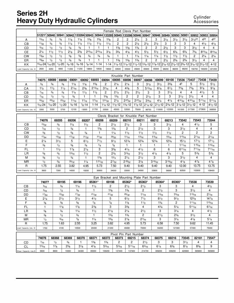
Rod End AccessoriesAccessories offered for the rod end of the cylinder include Rod Clevis, EyeBracket, Knuckle, Clevis Bracket and Pivot Pin. To select the proper partnumber for any desired accessory, refer to Chart A below and lookopposite the thread size of the rod end as indicated in the first column. ThePivot Pins, Eye Brackets and Clevis Brackets are listed opposite thethread size which their mating Knuckles or Clevises fit.
Chart A
Accessory Load CapacityThe various accessories on this and the followingpages have been load rated for your convenience.The load capacity in lbs., shown on the followingpage is the recommended maximum load for thataccessory based on a 4:1 design factor in tension.(Pivot Pin is rated in shear.) Before specifying,compare the actual load or the tension (pull) forceat maximum operating pressure of the cylinder withthe load capacity of the accessory you plan to use.If load or pull force of cylinder exceeds loadcapacity of accessory, consult factory.
Mounting PlatesMounting Plates for Style BB (clevis mounted) cylinders are offered. Toselect proper part number for your application, refer to Chart B, aboveright.
Series 2HBore Size
11/2"2", 21/2"
31/4"4"5"6"
Mtg. PlatePart No.
6919569196*8536169198*85362*85363
Chart B
For alignment coupler dimensions, see section C.*Cylinder accessory dimensions conform to NFPA recommended standard NFPA/T3.6.8 R1-1984, NFPA recom-mended standard fluid power systems — cylinder — dimensions for accessories for cataloged square head industrialtypes. Parker adopted this standard in April, 1985. Eye Brackets or Mounting Plates shipped before this date mayhave different dimensions and will not necessarily interchange with the NFPA standard. For dimensional information onolder style Eye Brackets or Mounting Plates consult Drawing #144805 or previous issues of this catalog.

For Cylinder Division Plant Locations – See Page II.
B
57
LE
CD
JKTHD
ER (MAX)
LUBEFITTING
CE
A
EX
JL DIA
Series 2HHeavy Duty Hydraulic Cylinders
Cylinder AccessoriesSpherical Bearing MountingStyle SB
Clevis Bracket
Order to fit Mounting Plate orRod Eye.
Pivot Pin
Pivot Pins are furnished with(2) Retainer Rings.
Parker offers a complete range of Cylinder Accessoriesto assure you of the greatest versatility in present orfuture cylinder applications. Accessories offered for the
respective cylinder include the Rod Eye, Pivot Pin andClevis Bracket. To select the proper part number for anydesired accessory refer to the charts below.
CL
CD
Spherical Rod Eye
Order to fit Piston Rod Thread Size.
Bore Sizes Series 2H 11/2 2 & 21/2 31/4 4 5 6Rod Eye Part No. 132290 132291 132292 132293 132294 132295
.5000-0005
11/16
7/87/16
13/16
3/47/16-20
7/8
.7500-0005
111/421/32
11/811/16
3/4-1615/16
1.0000-0005
11/217/87/8
11/417/16
1-1411/2
1.3750-0005
221/813/16
111/16
17/811/4-12
2
1.7500-0005
21/821/2
117/32
21/16
21/811/2-12
21/4
2.0000-0005
27/823/413/421/221/2
17/8-1223/4
CD
A
CE
EX
ER
LE
JK
JL
LOADCAPACITY
LBS.2644 9441 16860 28562 43005 70193
CD
CL
SHEARCAPACITY
LBS.
.4997-0004
19/16
.7497-0005
21/32
.9997-0005
21/2
1.3746-0006
35/16
1.7496-0006
47/32
1.9996-0007
415/16
19300 34300 65000 105200 1374008600
Bore Sizes Series 2H 11/2 2 & 21/2 31/4 4 5 6Pivot Pin Part No. 83962 83963 83964 83965 83966 83967
Bore Sizes Series 2H 11/2 2 & 21/2 31/4 4 5 6Part No. 83947 83948 83949 83950 83951 83952
CD
CF
CW
DD
E
F
FL
LR
M
MR
R
LOADCAPACITY
LBS.
1/27/16
1/213/32
31/2
11/215/16
1/25/8
2.05
3/421/32
5/817/32
33/45/82
13/87/81
2.76
17/83/4
17/32
51/23/4
21/2111/16
113/16
4.10
13/813/16
121/32
61/27/8
31/227/16
13/815/84.95
13/4117/32
11/429/32
81/211/441/227/813/421/16
6.58
213/411/229/32
105/811/25
35/16
223/87.92
9450 14300 20322 37800 503755770
Clevis Bracket
MR
LR
RE
DD DIA4 HOLES
F
M
FL
CW CWCF
+ .004+ .002
RE
CD

For additional information – call your local Parker Cylinder Distributor.
56
W
A
LE
CD CD
XC + STROKE
ZC + STROKE
XL + STROKE
CE
MALUBRICATIONFITTING
KE
ER
LUBRICATIONFITTING
NRKK
MS
4 2
EX3
1
42
EX3
1
XL + STROKE
X
X
A
A
X
X
A
A
XL + STROKE
Rod Style StyleRod Dia. 9 7
Bore No. MM KK KK A W XC XL ZC KE CD* CE ER EX LE MA MS NR71/8
71/2
81/4
81/2
83/8
87/8
85/8
97/8
101/4
101/8
115/8
12113/4
13131/4
131/4
131/4
145/8
145/8
145/8
145/8
Series 2HHeavy Duty Hydraulic Cylinders
Mounting InformationHead End Mounting
Recommended maximum swivel angle on each side of the cylinder centerline.
Spherical Bearing MountingStyle SB11/2" to 6" Bore Sizes
Thread
11/2
2
21/2
31/4
4
5
6
5/8
11
13/8
113/4
13/8
13/8
213/4
13/4
21/2
22
31/2
21/2
321/2
43
31/2
1(Std.)2
1(Std.)2
1(Std.)23
1(Std.)23
1(Std.)23
1(Std.)234
1(Std.)234
3/43/4
11/8
11/8
11/8
11/8
11/8
15/8
15/8
15/8
222
21/4
21/4
21/4
21/4
3333
71/4
75/8
81/2
83/4
85/8
91/8
87/8
101/2
107/8
103/4
117/8
121/4
1213
131/4
131/4
131/4
147/8
147/8
147/8
147/8
11/2
17/8
221/4
221/2
21/4
23/4
31/8
331/8
31/2
31/4
35/8
37/8
37/8
37/8
4444
Add Stroke
7/16-20—
3/4-16—
3/4-16——
1-14——
11/4-12——
11/2-12———
17/8-12———
—
7/16-20—
3/4-16—
3/4-163/4-16
—1-141-14—
11/4-1211/4-12
—11/2-1211/2-1211/2-12
—17/8-1217/8-1217/8-12
5/8
13/4
13/4
11/4
17/8
11/4
11/8
113/8
11/8
11/8
13/8
13/8
13/8
11/4
11/4
11/4
11/4
63/8
63/4
71/4
71/2
73/8
77/8
75/8
85/8
987/8
93/4
101/8
97/8
101/2
103/4
103/4
103/4
121/8
121/8
121/8
121/8
-.0005.5000-.0005.7500
-.0005
.7500
-.0005
1.0000
-.0005
1.3750
-.0005
1.7500
-.0005
2.0000
7/8
11/4
11/4
17/8
21/8
21/2
23/4
13/16
11/8
11/8
11/4
111/16
21/16
21/2
7/16
21/32
21/32
7/8
13/16
117/32
13/4
3/4
11/16
11/16
17/16
17/8
21/8
21/2
3/4
1
1
11/4
17/8
21/2
21/2
15/16
13/8
13/8
111/16
27/16
27/8
35/16
5/8
1
1
11/4
15/8
21/16
23/8
†Maximum operating pressure at 4:1 design factor is based on tensile strength of material. Pressure ratings are based on standard commercial bearing ratings.Note: for additional dimensions see Series 2H Style BB mount.Rod No. 1 is standard.*Dimension "CD" is hole diameter.
Note: Dimension X is the maximum off center mounting of the cylinder. Todetermine dimension X for various stroke lengths multiply the distancebetween pivot pin holes by tangent of angle a. For extended position use X= XL times 2X stroke.
Bore
11/2
2
21/2
31/4
4
5
6
Angle a
2½
21/2½
21/2½
3½
21/2½
3½
3½
Tan. of a
.035
.044
.044
.052
.044
.052
.052
Angle a
2½
41/2½
41/2½
3½
3½
3½
3½
Tan. of a
.035
.079
.079
.052
.052
.052
.052
Head End Mounted Cap End Mounted
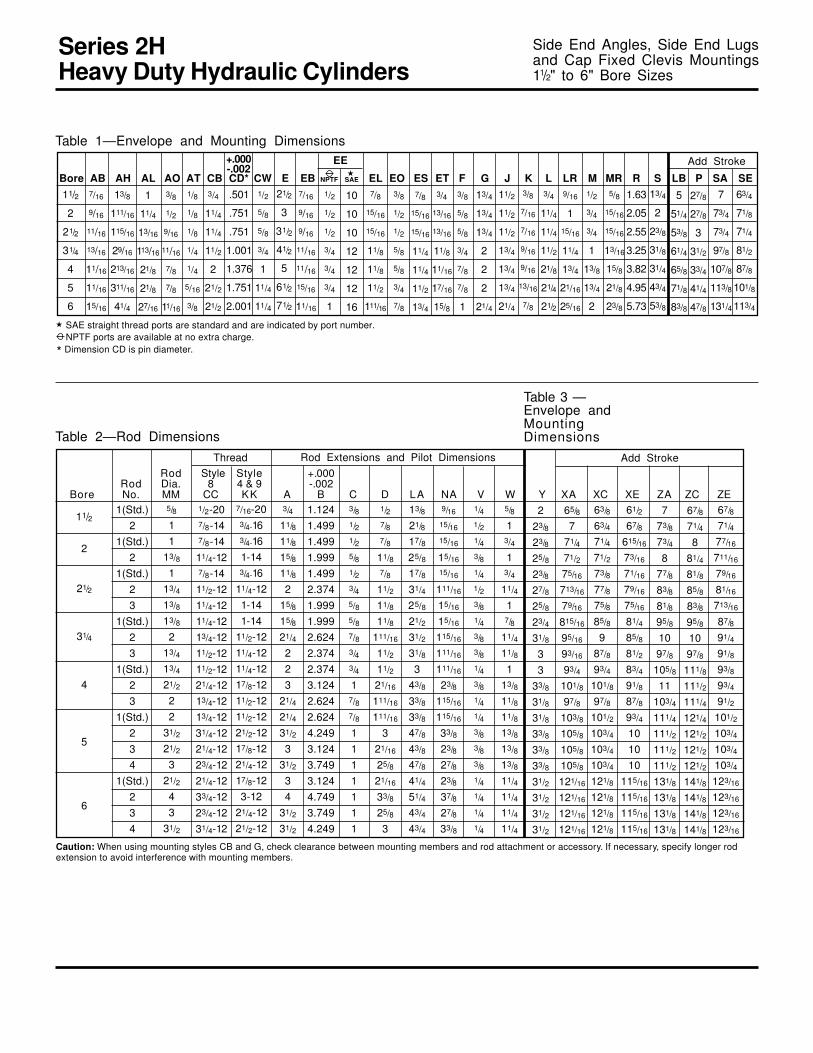
Table 1 — Dimensions
Cap End MountingTable 1
Max. Op.Bore PSI†
11/2 1250
2 2200
21/2 1450
31/4 1500
4 1850
5 2000
6 1800

Series 2HHeavy Duty Hydraulic Cylinders
SAE straight thread ports are standard and are indicated by port number.NPTF ports are available at no extra charge.
Table 3 —Envelope andMountingDimensionsTable 2— Rod Dimensions
Table 1— Envelope and Mounting Dimensions
★
����� � �����
For Cylinder Division Plant Locations – See Page II.
B
55
663/8
67/16
611/16
69/16
71/16
613/16
711/16
81/16
715/16
83/16
89/16
85/16
91/16
95/16
95/16
95/16
101/2
101/2
101/2
101/2
Style DDMinimum
Stroke0
1/4
1/8
3/8
1/8
0
1/4
Rod Style Style +.000Rod Dia. 8 4 & 9 -.002
Bore No. MM CC KK A B C D LA NA V W XG XI Y XJ ZB
Trunnion Mountings11/2" to 6" Bore Sizes
11/2
2
21/2
31/4
4
5
6
Thread
11/2
2
21/2
31/4
4
5
6
5/8
11
13/8
113/4
13/8
13/8
213/4
13/4
21/2
22
31/2
21/2
321/2
43
31/2
1/2-207/8-147/8-1411/4-127/8-1411/2-1211/4-1211/4-1213/4-1211/2-1211/2-1221/4-1213/4-1213/4-1231/4-1221/4-1223/4-1221/4-1233/4-1223/4-1231/4-12
1.1241.4991.4991.9991.4992.3741.9991.9992.6242.3742.3743.1242.6242.6244.2493.1243.7493.1244.7493.7494.249
1(Std.)2
1(Std.)2
1(Std.)23
1(Std.)23
1(Std.)23
1(Std.)234
1(Std.)234
Rod Extensions and Pilot Dimensions
3/4
11/8
11/8
15/8
11/8
215/8
15/8
21/4
223
21/4
21/4
31/2
331/2
34
31/2
31/2
3/81/21/25/81/23/45/85/87/83/43/4
17/87/8
1111111
1/27/87/8
11/87/8
11/2
11/8
11/8
111/16
11/2
11/2
21/16
111/16
111/16
321/16
25/8
21/16
33/8
25/8
3
7/16-203/4-163/4-161-143/4-16
11/4-121-141-14
11/2-1211/4-1211/4-1217/8-1211/2-1211/2-1221/2-1217/8-1221/4-1217/8-123-12
21/4-1221/2-12
13/8
21/8
17/8
25/8
17/8
31/4
25/8
21/2
31/2
31/8
343/8
33/8
33/8
47/8
43/8
47/8
41/4
51/4
43/4
43/4
9/16
15/16
15/16
15/16
15/16
111/16
15/16
15/16
115/16
111/16
111/16
23/8
115/16
115/16
33/8
23/8
27/8
23/8
37/8
27/8
33/8
1/41/21/43/81/41/23/81/43/83/81/43/81/41/43/83/83/81/41/41/41/4
5/8
13/4
13/4
11/4
17/8
11/4
11/8
113/8
11/8
11/8
13/8
13/8
13/8
11/4
11/4
11/4
11/4
223/8
23/8
25/8
23/8
27/8
25/8
23/4
31/8
33
33/8
31/8
31/8
33/8
33/8
33/8
31/2
31/2
31/2
31/2
Bore BD E F G J K TD TL TM UM UT UW LB P
Min.◆ ◆
Add Stroke
17/8
21/4
21/4
21/2
21/4
23/4
21/2
25/8
327/8
27/8
31/4
33
31/4
31/4
31/4
33/8
33/8
33/8
33/8
37/16
313/16
315/16
43/16
315/16
47/16
43/16
411/16
51/16
415/16
415/16
55/16
51/16
51/16
55/16
55/16
55/16
61/16
61/16
61/16
61/16
47/8
51/4
51/4
51/2
53/8
57/8
55/8
61/4
65/8
61/2
63/4
71/8
67/8
73/8
75/8
75/8
75/8
83/8
83/8
83/8
83/8
Table 3 —Envelope andMountingDimensions
21/2
3
31/2
41/2
5
61/2
71/2
EENPTF SAE★
1/2
1/2
1/2
3/4
3/4
3/4
1
10
10
10
12
12
12
16
3/8
5/8
5/8
3/4
7/8
7/8
1
13/4
13/4
13/4
2
2
2
21/4
11/2
11/2
11/2
13/4
13/4
13/4
21/4
3/8
7/16
7/16
9/16
9/16
13/16
7/8
1.000
1.375
1.375
1.750
1.750
1.750
2.000
Add Stroke
27/8
27/8
3
31/2
33/4
41/4
47/8
5
51/4
53/8
61/4
65/8
71/8
83/8
1
13/8
13/8
13/4
13/4
13/4
2
3
31/2
4
5
51/2
7
81/2
5
61/4
63/4
81/2
9
101/2
121/2
41/2
53/4
61/4
8
81/2
10
111/2
33/8
41/8
45/8
513/16
63/8
73/4
103/8
11/4
11/2
11/2
2
2
2
3
+.000-.001
◆ ◆ Dimension XI to be specified by customer.

W
VC
18
A
KK
LA
MM B
NAD WRENCHFLATS
W
VC
18
A
CC
LA
MM B
NAD WRENCHFLATS W
VC
18
A
KK
MM B
NAD WRENCHFLATS
Series 2HHeavy Duty Hydraulic Cylinders
Rod End Dimensions — see table 2Thread Style 9(NFPA Style SF)Small Female
Thread Style 8(NFPA Style IM)Intermediate Male
Thread Style 4(NFPA Style SM)Small Male
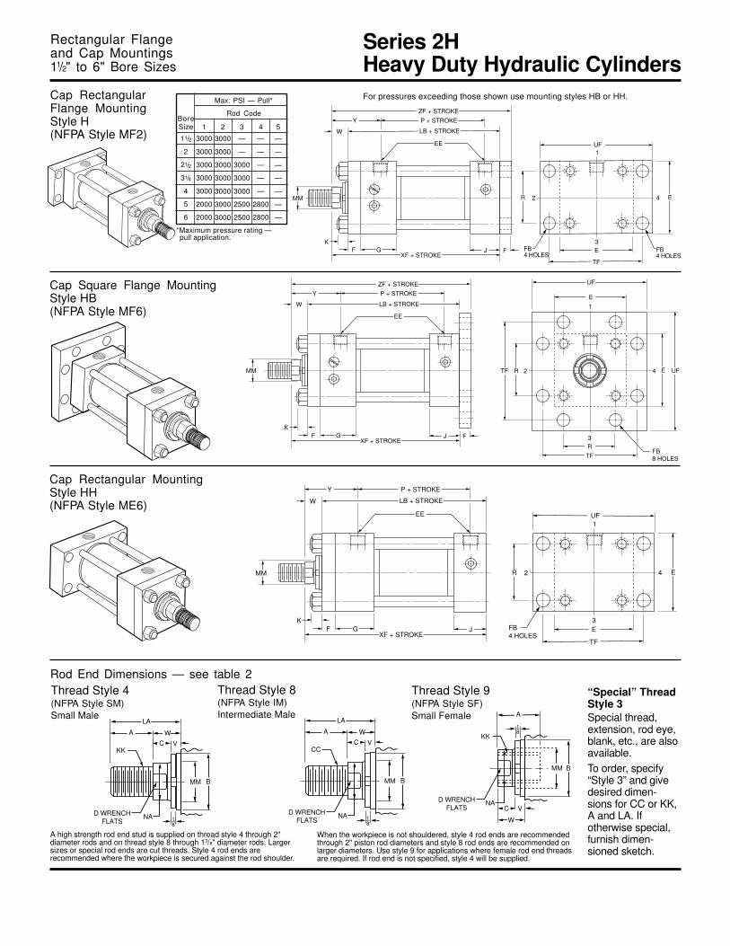
A high strength rod end stud is supplied on thread style 4 through 2"diameter rods and on thread style 8 through 13/8" diameter rods. Largersizes or special rod ends are cut threads. Style 4 rod ends arerecommended where the workpiece is secured against the rod shoulder.
When the workpiece is not shouldered, style 4 rod ends are recommendedthrough 2" piston rod diameters and style 8 rod ends are recommended onlarger diameters. Use style 9 for applications where female rod end threadsare required. If rod end is not specified, style 4 will be supplied.
“Special” ThreadStyle 3Special thread,extension, rod eye,blank, etc., are alsoavailable.To order, specify“Style 3” and givedesired dimen-sions for CC or KK,A and LA. Ifotherwise special,furnish dimen-sioned sketch.
For additional information – call your local Parker Cylinder Distributor.
54
4 2EUW TD
R18
ETMTL
G
BD
XI
F J3
1
LB + STROKEP + STROKE
ZB + STROKE
W
K
EE
Y
UM
MM
TL
4 2E TD
R18
ETL TL G
XG
F J
3
1
LB + STROKE
P + STROKEZB + STROKE
W
K
EE
Y
UT
MM
4 2E TD
R18
ETL TL G
XJ + STROKE
F J
3
1
LB + STROKE
P + STROKEZB + STROKE
W
K
EE
Y
UT
MM
Head Trunnion MountingStyle D(NFPA Style MT1)
Cap Trunnion MountingStyle DB(NFPA Style MT2)
Intermediate Fixed Trunnion MountingStyle DD(NFPA Style MT4)
Trunnion Mountings11/2" to 6" Bore Sizes
Series 2HHeavy Duty Hydraulic Cylinders
SAE straight thread ports are standard and are indicated by port number.NPTF ports are available at no extra charge.
Table 3 —Envelope andMountingDimensionsTable 2— Rod Dimensions
Table 1— Envelope and Mounting Dimensions
★
�� �� � ������
For Cylinder Division Plant Locations – See Page II.
B
53
67/8
71/4
77/16
711/16
79/16
81/16
713/16
87/8
91/4
91/8
93/8
93/4
91/2
101/2
103/4
103/4
103/4
123/16
123/16
123/16
123/16
EE Add Stroke
Side End Angles, Side End Lugsand Cap Fixed Clevis Mountings11/2" to 6" Bore Sizes
ThreadRod Style Style +.000
Rod Dia. 8 4 & 9 -.002Bore No. MM CC KK A B C D LA NA V W Y XA XC XE ZA ZC ZE
11/2
2
21/2
31/4
4
5
6
5/8
11
13/8
113/4
13/8
13/8
213/4
13/4
21/2
22
31/2
21/2
321/2
43
31/2
1/2-207/8-147/8-1411/4-127/8-1411/2-1211/4-1211/4-1213/4-1211/2-1211/2-1221/4-1213/4-1213/4-1231/4-1221/4-1223/4-1221/4-1233/4-1223/4-1231/4-12
1.1241.4991.4991.9991.4992.3741.9991.9992.6242.3742.3743.1242.6242.6244.2493.1243.7493.1244.7493.7494.249
1(Std.)2
1(Std.)2
1(Std.)23
1(Std.)23
1(Std.)23
1(Std.)234
1(Std.)234
Rod Extensions and Pilot Dimensions
3/4
11/8
11/8
15/8
11/8
215/8
15/8
21/4
223
21/4
21/4
31/2
331/2
34
31/2
31/2
3/81/21/25/81/23/45/85/87/83/43/4
17/87/8
1111111
1/27/87/8
11/87/8
11/2
11/8
11/8
111/16
11/2
11/2
21/16
111/16
111/16
321/16
25/8
21/16
33/8
25/8
3
Add Stroke
7/16-203/4-163/4-161-143/4-16
11/4-121-141-14
11/2-1211/4-1211/4-1217/8-1211/2-1211/2-1221/2-1217/8-1221/4-1217/8-123-12
21/4-1221/2-12
11/2
2
21/2
31/4
4
5
6
* Dimension CD is pin diameter.
Bore AB AH AL AO AT CB CD* CW E EB NPTF SAE EL EO ES ET F G J K L LR M MR R S LB P SA SE.501
.751
.751
1.001
1.376
1.751
2.001
21/2
3
31/2
41/2
5
61/2
71/2
5
51/4
53/8
61/4
65/8
71/8
83/8
27/8
27/8
3
31/2
33/4
41/4
47/8
3/8
5/8
5/8
3/4
7/8
7/8
1
13/4
13/4
13/4
2
2
2
21/4
11/2
11/2
11/2
13/4
13/4
13/4
21/4
3/8
7/16
7/16
9/16
9/16
13/16
7/8
9/16
1
15/16
11/4
13/4
21/16
25/16
3/4
11/4
11/4
11/2
21/8
21/4
21/2
1/2
3/4
3/4
1
13/8
13/4
2
5/8
15/16
15/16
13/16
15/8
21/8
23/8
1.63
2.05
2.55
3.25
3.82
4.95
5.73
13/4
2
23/8
31/8
31/4
43/4
53/8
3/8
1/2
1/2
5/8
5/8
3/4
7/8
7
73/4
73/4
97/8
107/8
113/8
131/4
63/4
71/8
71/4
81/2
87/8
101/8
113/4
1/2
1/2
1/2
3/4
3/4
3/4
1
10
10
10
12
12
12
16
3/4
13/16
13/16
11/8
11/16
17/16
15/8
7/8
15/16
15/16
11/4
11/4
11/2
13/4
7/8
15/16
15/16
11/8
11/8
11/2
111/16
★
7/16
9/16
11/16
13/16
11/16
11/16
15/16
7/16
9/16
9/16
11/16
11/16
15/16
11/16
13/8
111/16
115/16
29/16
213/16
311/16
41/4
1
11/4
13/16
113/16
21/8
21/8
27/16
3/8
1/2
9/16
11/16
7/8
7/8
11/16
1/8
1/8
1/8
1/4
1/4
5/16
3/8
3/4
11/4
11/4
11/2
2
21/2
21/2
1/2
5/8
5/8
3/4
1
11/4
11/4
13/8
21/8
17/8
25/8
17/8
31/4
25/8
21/2
31/2
31/8
343/8
33/8
33/8
47/8
43/8
47/8
41/4
51/4
43/4
43/4
9/16
15/16
15/16
15/16
15/16
111/16
15/16
15/16
115/16
111/16
111/16
23/8
115/16
115/16
33/8
23/8
27/8
23/8
37/8
27/8
33/8
1/41/21/43/81/41/23/81/43/83/81/43/81/41/43/83/83/81/41/41/41/4
5/8
13/4
13/4
11/4
17/8
11/4
11/8
113/8
11/8
11/8
13/8
13/8
13/8
11/4
11/4
11/4
11/4
223/8
23/8
25/8
23/8
27/8
25/8
23/4
31/8
33
33/8
31/8
31/8
33/8
33/8
33/8
31/2
31/2
31/2
31/2
65/8
771/4
71/2
75/16
713/16
79/16
815/16
95/16
93/16
93/4
101/8
97/8
103/8
105/8
105/8
105/8
121/16
121/16
121/16
121/16
63/8
63/4
71/4
71/2
73/8
77/8
75/8
85/8
987/8
93/4
101/8
97/8
101/2
103/4
103/4
103/4
121/8
121/8
121/8
121/8
61/2
67/8
615/16
73/16
71/16
79/16
75/16
81/4
85/8
81/2
83/4
91/8
87/8
93/4
101010
115/16
115/16
115/16
115/16
773/8
73/4
877/8
83/8
81/8
95/8
1097/8
105/8
11103/4
111/4
111/2
111/2
111/2
131/8
131/8
131/8
131/8
67/8
71/4
881/4
81/8
85/8
83/8
95/8
1097/8
111/8
111/2
111/4
121/4
121/2
121/2
121/2
141/8
141/8
141/8
141/8
Table 3 —Envelope andMountingDimensions
+.000-.002
Caution: When using mounting styles CB and G, check clearance between mounting members and rod attachment or accessory. If necessary, specify longer rodextension to avoid interference with mounting members.

W
VC
18
A
KK
LA
MM B
NAD WRENCHFLATS
W
VC
18
A
CC
LA
MM B
NAD WRENCHFLATS W
VC
18
A
KK
MM B
NAD WRENCHFLATS
Series 2HHeavy Duty Hydraulic Cylinders
Rod End Dimensions — see table 2Thread Style 9(NFPA Style SF)Small Female
Thread Style 8(NFPA Style IM)Intermediate Male
Thread Style 4(NFPA Style SM)Small Male
A high strength rod end stud is supplied on thread style 4 through 2"diameter rods and on thread style 8 through 13/8" diameter rods. Largersizes or special rod ends are cut threads. Style 4 rod ends arerecommended where the workpiece is secured against the rod shoulder.
When the workpiece is not shouldered, style 4 rod ends are recommendedthrough 2" piston rod diameters and style 8 rod ends are recommended onlarger diameters. Use style 9 for applications where female rod end threadsare required. If rod end is not specified, style 4 will be supplied.
“Special” ThreadStyle 3Special thread,extension, rod eye,blank, etc., are alsoavailable.To order, specify“Style 3” and givedesired dimen-sions for CC or KK,A and LA. Ifotherwise special,furnish dimen-sioned sketch.
For additional information – call your local Parker Cylinder Distributor.
52
42 E
CBCW CW
XC + STROKE
GK
J M3
1
LB + STROKE
P + STROKEZC + STROKE
W
CD
PIVOT PIN
EE
Y
L
LR
E
F
MR
MM
4
E
AHAT
GFK
ALAO JAT
3 1 S
LB + STROKE
P + STROKEXA + STROKEZA + STROKE
W AB6 HOLES
EE
Y
AL AO
E
2
SA + STROKE
MM
Side End Lugs MountingStyle G(NFPA Style MS7)
Cap Fixed Clevis MountingStyle BB(NFPA Style MP1)
Side End Angles MountingStyle CB(NFPA Style MS1)
Side End Angles, Side End Lugsand Cap Fixed Clevis Mountings11/2" to 6" Bore Sizes
The maximum recommended operating pressurefor Style CB is 500 psi. The recommendedminimum stroke length is two times the bore size.
Tie rods thread into cap on all bore sizes.
ZE + STROKE
XE + STROKE
SE + STROKE
P + STROKE
LB + STROKE
EE
Y
W K
J ELEL EOEO F G
MM
E
E
R
EB 4 HOLES
ETFor this cylindermounting style, boththe mounting lugsand cylinder end capsmust rest on a firm surface.

Series 2HHeavy Duty Hydraulic Cylinders
SAE straight thread ports are standard and are indicated by port number.NPTF ports are available at no extra charge.
Table 3 —Envelope andMountingDimensionsTable 2— Rod Dimensions
Table 1— Envelope and Mounting Dimensions
★
����� � ������
For Cylinder Division Plant Locations – See Page II.
B
51
663/8
67/16
611/16
69/16
71/16
613/16
711/16
81/16
715/16
83/16
89/16
85/16
91/16
95/16
95/16
95/16
101/2
101/2
101/2
101/2
Side Lugs, Centerline Lugsand Side Tapped Mountings11/2" to 6" Bore Sizes
ThreadRod Style Style +.000
Rod Dia. 8 4 & 9 -.002Bore No. MM CC KK A B C D LA NA V W ND XS XT Y ZB
11/2
2
21/2
31/4
4
5
6
5/8
11
13/8
113/4
13/8
13/8
213/4
13/4
21/2
22
31/2
21/2
321/2
43
31/2
1/2-207/8-147/8-1411/4-127/8-1411/2-1211/4-1211/4-1213/4-1211/2-1211/2-1221/4-1213/4-1213/4-1231/4-1221/4-1223/4-1221/4-1233/4-1223/4-1231/4-12
1.1241.4991.4991.9991.4992.3741.9991.9992.6242.3742.3743.1242.6242.6244.2493.1243.7493.1244.7493.7494.249
1(Std.)2
1(Std.)2
1(Std.)23
1(Std.)23
1(Std.)23
1(Std.)234
1(Std.)234
Rod Extensions and Pilot Dimensions
3/4
11/8
11/8
15/8
11/8
215/8
15/8
21/4
223
21/4
21/4
31/2
331/2
34
31/2
31/2
3/81/21/25/81/23/45/85/87/83/43/4
17/87/8
1111111
1/27/87/8
11/87/8
11/2
11/8
11/8
111/16
11/2
11/2
21/16
111/16
111/16
321/16
25/8
21/16
33/8
25/8
3
7/16-203/4-163/4-161-143/4-16
11/4-121-141-14
11/2-1211/4-1211/4-1217/8-1211/2-1211/2-1221/2-1217/8-1221/4-1217/8-123-12
21/4-1221/2-12
13/8
21/8
17/8
25/8
17/8
31/4
25/8
21/2
31/2
31/8
343/8
33/8
33/8
47/8
43/8
47/8
41/4
51/4
43/4
43/4
9/16
15/16
15/16
15/16
15/16
111/16
15/16
15/16
115/16
111/16
111/16
23/8
115/16
115/16
33/8
23/8
27/8
23/8
37/8
27/8
33/8
1/41/21/43/81/41/23/81/43/83/81/43/81/41/43/83/83/81/41/41/41/4
5/8
13/4
13/4
11/4
17/8
11/4
11/8
113/8
11/8
11/8
13/8
13/8
13/8
11/4
11/4
11/4
11/4
3/83/8
7/16
7/16
1/21/21/2
11/16
11/16
11/16
11/16
11/16
11/16
1111
11/4
11/4
11/4
11/4
Bore E F G J K NT SB* ST SU SW TN TS US
11/2
2
21/2
31/4
4
5
6
21/2
3
31/2
41/2
5
61/2
71/2
EENPTF SAE★
1/2
1/2
1/2
3/4
3/4
3/4
1
10
10
10
12
12
12
16
3/8
5/8
5/8
3/4
7/8
7/8
1
13/4
13/4
13/4
2
2
2
21/4
11/2
11/2
11/2
13/4
13/4
13/4
21/4
3/8
7/16
7/16
9/16
9/16
13/16
7/8
LB P SN SS
37/8
35/8
33/8
41/8
4
41/2
51/8
27/8
27/8
3
31/2
33/4
41/4
51/8
27/8
27/8
3
31/2
33/4
41/4
47/8
5
51/4
53/8
61/4
65/8
71/8
83/8
Add Stroke
3/8-16
1/2-13
5/8-11
3/4-10
1-8
1-8
11/4-7
7/16
9/16
13/16
13/16
11/16
11/16
15/16
1/2
3/4
1
1
11/4
11/4
11/2
15/16
11/4
19/16
19/16
2
2
21/2
3/8
1/2
11/16
11/16
7/8
7/8
11/8
3/4
15/16
15/16
11/2
21/16
215/16
35/16
31/4
4
47/8
57/8
63/4
81/4
93/4
4
5
61/4
71/4
81/2
10
12
* Upper surface spotfaced for socket head screws.
Table 3 —Envelope andMountingDimensions
223/8
23/8
25/8
23/8
27/8
25/8
23/4
31/8
33
33/8
31/8
31/8
33/8
33/8
33/8
31/2
31/2
31/2
31/2
AddStroke
223/8
23/8
25/8
23/8
27/8
25/8
23/4
31/8
33
33/8
31/8
31/8
33/8
33/8
33/8
31/2
31/2
31/2
31/2
13/8
13/4
17/8
21/8
21/16
29/16
25/16
25/16
211/16
29/16
23/4
31/8
27/8
27/8
31/8
31/8
31/8
33/8
33/8
33/8
33/8

W
VC
18
A
KK
LA
MM B
NAD WRENCHFLATS
W
VC
18
A
CC
LA
MM B
NAD WRENCHFLATS W
VC
18
A
KK
MM B
NAD WRENCHFLATS
Series 2HHeavy Duty Hydraulic Cylinders
Rod End Dimensions — see table 2Thread Style 9(NFPA Style SF)Small Female
Thread Style 8(NFPA Style IM)Intermediate Male
Thread Style 4(NFPA Style SM)Small Male
A high strength rod end stud is supplied on thread style 4 through 2"diameter rods and on thread style 8 through 13/8" diameter rods. Largersizes or special rod ends are cut threads. Style 4 rod ends arerecommended where the workpiece is secured against the rod shoulder.
When the workpiece is not shouldered, style 4 rod ends are recommendedthrough 2" piston rod diameters and style 8 rod ends are recommended onlarger diameters. Use style 9 for applications where female rod end threadsare required. If rod end is not specified, style 4 will be supplied.
“Special” ThreadStyle 3Special thread,extension, rod eye,blank, etc., are alsoavailable.To order, specify“Style 3” and givedesired dimen-sions for CC or KK,A and LA. Ifotherwise special,furnish dimen-sioned sketch.
For additional information – call your local Parker Cylinder Distributor.
50
4E
ST
E-.0052-.010
E
TS
SW
SW
SW
SW
F
XS SS + STROKE
SB4 HOLES
3
1
MM
LB + STROKE
P + STROKE
ZB + STROKE
W
K
EE
Y
US
2
SU SUSW
G J
SW
4 2E
E -.0052 -.010
TN F
XT SN + STROKENT THREAD, ND DEEP4 TAPPED MTG. HOLES
3
1
LB + STROKE
P + STROKEZB + STROKE
W K
EE
Y
E
J KG
MM
Side Lug MountingsStyle C(NFPA Style MS2)
Centerline Lugs MountingStyle E(NFPA Style MS3)
Side Tapped MountingStyle F(NFPA Style MS4)
Side Lugs, Centerline Lugsand Side Tapped Mountings11/2" to 6" Bore Sizes
4E
ST
E
TS
SW
SW
SW
SW
F
XS SS + STROKE
SB4 HOLES
3
1
LB + STROKE
P + STROKEZB + STROKE
W
K
EE
Y
US
2
SU SUSW
G J
MM
SW

Series 2HHeavy Duty Hydraulic Cylinders
SAE straight thread ports are standard and are indicated by port number.NPTF ports are available at no extra charge.
Table 3 —Envelope andMountingDimensionsTable 2— Rod Dimensions
Table 1— Envelope and Mounting Dimensions
★
����� � �!"�#
For Cylinder Division Plant Locations – See Page II.
B
49
663/8
65/8
67/8
63/4
71/4
777/8
81/4
81/8
81/2
87/8
85/8
91/8
93/8
93/8
93/8
105/8
105/8
105/8
105/8
Rectangular Flangeand Cap Mountings11/2" to 6" Bore Sizes
EE
Bore E F FB G J K R TF UFAdd Stroke
11/2
2
21/2
31/4
4
5
6
21/2
3
31/2
41/2
5
61/2
71/2
1/2
1/2
1/2
3/4
3/4
3/4
1
10
10
10
12
12
12
16
3/8
5/8
5/8
3/4
7/8
7/8
1
13/4
13/4
13/4
2
2
2
21/4
11/2
11/2
11/2
13/4
13/4
13/4
21/4
3/8
7/16
7/16
9/16
9/16
13/16
7/8
1.63
2.05
2.55
3.25
3.82
4.95
5.73
37/16
41/8
45/8
57/8
63/8
83/16
97/16
41/4
51/8
55/8
71/8
75/8
93/4
111/4
5
51/4
53/8
61/4
65/8
71/8
83/8
7/16
9/16
9/16
11/16
11/16
15/16
11/16
NPTF SAE★ LB P
27/8
27/8
3
31/2
33/4
41/4
47/8
Table 3 —Envelope andMountingDimensions
ThreadRod Style Style +.000
Rod Dia. 8 4 & 9 -.002Bore No. MM CC KK A B C D LA NA V W WF Y XF ZF
11/2
2
21/2
31/4
4
5
6
5/8
11
13/8
113/4
13/8
13/8
213/4
13/4
21/2
22
31/2
21/2
321/2
43
31/2
1/2-207/8-147/8-1411/4-127/8-1411/2-1211/4-1211/4-1213/4-1211/2-1211/2-1221/4-1213/4-1213/4-1231/4-1221/4-1223/4-1221/4-1233/4-1223/4-1231/4-12
1.1241.4991.4991.9991.4992.3741.9991.9992.6242.3742.3743.1242.6242.6244.2493.1243.7493.1244.7493.7494.249
1(Std.)2
1(Std.)2
1(Std.)23
1(Std.)23
1(Std.)23
1(Std.)234
1(Std.)234
Rod Extensions and Pilot Dimensions
3/4
11/8
11/8
15/8
11/8
215/8
15/8
21/4
223
21/4
21/4
31/2
331/2
34
31/2
31/2
3/81/21/25/81/23/45/85/87/83/43/4
17/87/8
1111111
1/27/87/8
11/87/8
11/2
11/8
11/8
111/16
11/2
11/2
21/16
111/16
111/16
321/16
25/8
21/16
33/8
25/8
3
7/16-203/4-163/4-161-143/4-16
11/4-121-141-14
11/2-1211/4-1211/4-1217/8-1211/2-1211/2-1221/2-1217/8-1221/4-1217/8-123-12
21/4-1221/2-12
13/8
21/8
17/8
25/8
17/8
31/4
25/8
21/2
31/2
31/8
343/8
33/8
33/8
47/8
43/8
47/8
41/4
51/4
43/4
43/4
9/16
15/16
15/16
15/16
15/16
111/16
15/16
15/16
115/16
111/16
111/16
23/8
115/16
115/16
33/8
23/8
27/8
23/8
37/8
27/8
33/8
1/41/21/43/81/41/23/81/43/83/81/43/81/41/43/83/83/81/41/41/41/4
5/8
13/4
13/4
11/4
17/8
11/4
11/8
113/8
11/8
11/8
13/8
13/8
13/8
11/4
11/4
11/4
11/4
223/8
23/8
25/8
23/8
27/8
25/8
23/4
31/8
33
33/8
31/8
31/8
33/8
33/8
33/8
31/2
31/2
31/2
31/2
113/8
13/8
15/8
13/8
17/8
15/8
15/8
217/8
17/8
21/4
22
21/4
21/4
21/4
21/4
21/4
21/4
21/4
Add Stroke
55/8
66
61/4
61/8
65/8
63/8
71/8
71/2
73/8
75/8
873/4
81/4
81/2
81/2
81/2
95/8
95/8
95/8
95/8
W
VC
18
A
KK
LA
MM B
NAD WRENCHFLATS
W
VC
18
A
CC
LA
MM B
NAD WRENCHFLATS W
VC
18
A
KK
MM B
NAD WRENCHFLATS
Series 2HHeavy Duty Hydraulic Cylinders
Rod End Dimensions — see table 2Thread Style 9(NFPA Style SF)Small Female
Thread Style 8(NFPA Style IM)Intermediate Male
Thread Style 4(NFPA Style SM)Small Male
A high strength rod end stud is supplied on thread style 4 through 2"diameter rods and on thread style 8 through 13/8" diameter rods. Largersizes or special rod ends are cut threads. Style 4 rod ends arerecommended where the workpiece is secured against the rod shoulder.
When the workpiece is not shouldered, style 4 rod ends are recommendedthrough 2" piston rod diameters and style 8 rod ends are recommended onlarger diameters. Use style 9 for applications where female rod end threadsare required. If rod end is not specified, style 4 will be supplied.
“Special” ThreadStyle 3Special thread,extension, rod eye,blank, etc., are alsoavailable.To order, specify“Style 3” and givedesired dimen-sions for CC or KK,A and LA. Ifotherwise special,furnish dimen-sioned sketch.
For additional information – call your local Parker Cylinder Distributor.
48
42R E
E
TF
GXF + STROKE
FK
J3
1
LB + STROKE
P + STROKE
W
EE
Y
UF
FB4 HOLES
MM
42R E
E
TF
GXF + STROKE
FK
J3
1
LB + STROKE
P + STROKEZF + STROKE
W
EE
Y
UF
F FB4 HOLES
MM
FB4 HOLES
GXF + STROKE
FK
J
LB + STROKE
P + STROKEZF + STROKE
W
EE
Y
F
2 4RTF E UF
RTF
FB8 HOLES
3
UF
1E
MM
Cap Square Flange MountingStyle HB(NFPA Style MF6)
Cap Rectangular MountingStyle HH(NFPA Style ME6)
Rectangular Flangeand Cap Mountings11/2" to 6" Bore Sizes
For pressures exceeding those shown use mounting styles HB or HH.Cap RectangularFlange MountingStyle H(NFPA Style MF2)
BoreSize
11/2
2
21/2
31/4
4
5
6
2
3000
3000
3000
3000
3000
3000
3000
*Maximum pressure rating — pull application.
3
—
—
3000
3000
3000
2500
2500
4
—
—
—
—
—
2800
2800
5
—
—
—
—
—
—
—
Rod Code
Max. PSI — Pull*
1
3000
3000
3000
3000
3000
2000
2000

Series 2HHeavy Duty Hydraulic Cylinders
SAE straight thread ports are standard and are indicated by port number.NPTF ports are available at no extra charge.
Table 3 —Envelope andMountingDimensionsTable 2— Rod Dimensions
Table 1— Envelope and Mounting Dimensions
★
$�%�& ' (�)*�+
For Cylinder Division Plant Locations – See Page II.
B
47
Rod Style Style +.000Rod Dia. 8 4 & 9 -.002
Bore No. MM CC KK A B C D KB LA LAF NA V W RD RT WF Y ZB6
63/8
67/16
611/16
69/16
71/16
613/16
711/16
81/16
715/16
83/16
89/16
85/16
91/16
95/16
95/16
95/16
101/2
101/2
101/2
101/2
EE
Rectangluar Flangeand Head Mountings11/2" to 6" Bore Sizes
Bore E F FB G J K R TF UF
Thread
11/2
2
21/2
31/4
4
5
6
5/8
11
13/8
113/4
13/8
13/8
213/4
13/4
21/2
22
31/2
21/2
321/2
43
31/2
Add Stroke
11/2
2
21/2
31/4
4
5
6
21/2
3
31/2
41/2
5
61/2
71/2
1/2
1/2
1/2
3/4
3/4
3/4
1
10
10
10
12
12
12
16
3/8
5/8
5/8
3/4
7/8
7/8
1
13/4
13/4
13/4
2
2
2
21/4
11/2
11/2
11/2
13/4
13/4
13/4
21/4
3/8
7/16
7/16
9/16
9/16
13/16
7/8
1.63
2.05
2.55
3.25
3.82
4.95
5.73
37/16
41/8
45/8
57/8
63/8
83/16
97/16
41/4
51/8
55/8
71/8
75/8
93/4
111/4
5
51/4
53/8
61/4
65/8
71/8
83/8
7/16
9/16
9/16
11/16
11/16
15/16
11/16
1/2-207/8-147/8-1411/4-127/8-1411/2-1211/4-1211/4-1213/4-1211/2-1211/2-1221/4-1213/4-1213/4-1231/4-1221/4-1223/4-1221/4-1233/4-1223/4-1231/4-12
1.1241.4991.4991.9991.4992.3741.9991.9992.6242.3742.3743.1242.6242.6244.2493.1243.7493.1244.7493.7494.249
1(Std.)2
1(Std.)2
1(Std.)23
1(Std.)23
1(Std.)23
1(Std.)234
1(Std.)234
Rod Extensions and Pilot Dimensions
NPTF SAE★ LB LG P
45/8
45/8
43/4
51/2
53/4
61/4
73/8
27/8
27/8
3
31/2
33/4
41/4
47/8
223/8
23/8
25/8
23/8
27/8
25/8
23/4
31/8
33
33/8
31/8
31/8
33/8
33/8
33/8
31/2
31/2
31/2
31/2
3/4
11/8
11/8
15/8
11/8
215/8
15/8
21/4
223
21/4
21/4
31/2
331/2
34
31/2
31/2
3/81/21/25/81/23/45/85/87/83/43/4
17/87/8
1111111
1/27/87/8
11/87/8
11/2
11/8
11/8
111/16
11/2
11/2
21/16
111/16
111/16
321/16
25/8
21/16
33/8
25/8
3
13/8
21/8
17/8
25/8
17/8
31/4
25/8
21/2
31/2
31/8
343/8
33/8
33/8
47/8
43/8
47/8
41/4
51/4
43/4
43/4
9/16
15/16
15/16
15/16
15/16
111/16
15/16
15/16
115/16
111/16
111/16
23/8
115/16
115/16
33/8
23/8
27/8
23/8
37/8
27/8
33/8
1/41/21/43/81/41/23/81/43/83/81/43/81/41/43/83/83/81/41/41/41/4
5/8
13/4
13/4
11/4
17/8
11/4
11/8
113/8
11/8
11/8
13/8
13/8
13/8
11/4
11/4
11/4
11/4
AddStroke
113/8
13/8
15/8
13/8
17/8
15/8
15/8
217/8
17/8
21/4
22
21/4
21/4
21/4
21/4
21/4
21/4
21/4
3/83/83/83/83/83/83/83/85/83/83/85/85/85/85/85/85/85/83/45/85/8
21/8
21/2
21/2
321/2
31/2
334
31/2
31/2
41/2
44
53/4
41/2
51/4
41/2
61/2
51/4
53/4
13/4
21/2
21/2
31/4
21/2
37/8
31/4
31/4
41/4
37/8
37/8
51/4
41/4
41/4
53/4
51/4
53/4
51/4
61/4
53/4
53/4
0001/4
01/41/41/41/81/41/41/41/81/81/41/41/41/41/41/41/4
7/16-203/4-163/4-161-143/4-16
11/4-121-141-14
11/2-1211/4-1211/4-1217/8-1211/2-1211/2-1221/2-1217/8-1221/4-1217/8-123-12
21/4-1221/2-12
Table 3 —Envelope andMountingDimensions

W
VC
18
A
KK
LA
MM B
NAD WRENCHFLATS
W
VC
18
A
CC
LA
MM B
NAD WRENCHFLATS W
VC
18
A
KK
MM B
NAD WRENCHFLATS
Series 2HHeavy Duty Hydraulic Cylinders
Rod End Dimensions — see table 2Thread Style 9(NFPA Style SF)Small Female
Thread Style 8(NFPA Style IM)Intermediate Male
Thread Style 4(NFPA Style SM)Small Male
A high strength rod end stud is supplied on thread style 4 through 2"diameter rods and on thread style 8 through 13/8" diameter rods. Largersizes or special rod ends are cut threads. Style 4 rod ends arerecommended where the workpiece is secured against the rod shoulder.
When the workpiece is not shouldered, style 4 rod ends are recommendedthrough 2" piston rod diameters and style 8 rod ends are recommended onlarger diameters. Use style 9 for applications where female rod end threadsare required. If rod end is not specified, style 4 will be supplied.
“Special” ThreadStyle 3Special thread,extension, rod eye,blank, etc., are alsoavailable.To order, specify“Style 3” and givedesired dimen-sions for CC or KK,A and LA. Ifotherwise special,furnish dimen-sioned sketch.
For additional information – call your local Parker Cylinder Distributor.
46
4 2E R
ETF
GRTFB4 HOLES
J K3
1
BRD
LG + STROKE
P + STROKEZB + STROKE
K
EE
Y
UF
LAF
A
C
NA
KK
D WRENCHFLATS
WFRT KK THREAD STYLE 4
CC THREAD STYLE 8
WF
KB
B
18
MM
4 2E R
ETF G
FFB4 HOLES
J K3
1
LB + STROKE
P + STROKE
ZB + STROKE
W K
EE
Y
UF
WF
MM
4 2EUF R TF
RTF G
FFB8 HOLES
J K
3
LB + STROKE
P + STROKE
ZB + STROKE
W K
EE
Y
UF
1E
WF
MM
Head RectangularFlange MountingStyle J(NFPA Style MF1)
Head Square Flange MountingStyle JB(NFPA Style MF5)
Head Rectangular MountingStyle JJ(NFPA Style ME5)
Rectangular Flangeand Head Mountings11/2" to 6" Bore Sizes
For pressures exceeding those shown use mounting styles JB or JJ.
BoreSize
11/2
2
21/2
31/4
4
5
6
2
1500
1500
1500
1500
1500
750
750
*Maximum pressure rating — push application.
For Style “J” Mount
3
—
—
1900
2100
1800
1650
1450
4
—
—
—
—
—
1200
1100
5
—
—
—
—
—
—
—
Rod Code
Max. PSI — Push*
1
2500
2500
2500
2500
2500
2200
1800

Series 2HHeavy Duty Hydraulic Cylinders
SAE straight thread ports are standard and are indicated by port number.NPTF ports are available at no extra charge.
Table 3 —Envelope andMountingDimensionsTable 2— Rod Dimensions
Table 1— Envelope and Mounting Dimensions
★
,�-�. / 0�12�3
For Cylinder Division Plant Locations – See Page II.
B
45
55/8
66
61/4
61/8
65/8
63/8
71/8
71/2
73/8
75/8
873/4
81/4
81/2
81/2
81/2
95/8
95/8
95/8
95/8
Bore AA BB DD E F G J K R
5/8
13/4
13/4
11/4
17/8
11/4
11/8
113/8
11/8
11/8
13/8
13/8
13/8
11/4
11/4
11/4
11/4
ThreadRod Style Style +.000
Rod Dia. 8 4 & 9 -.002Bore No. MM CC KK A B C D LA NA V W Y ZB ZJ
11/2
2
21/2
31/4
4
5
6
5/8
11
13/8
113/4
13/8
13/8
213/4
13/4
21/2
22
31/2
21/2
321/2
43
31/2
EENPTF SAE★
Add Stroke
27/8
27/8
3
31/2
33/4
41/4
47/8
11/2
2
21/2
31/4
4
5
6
2.3
2.9
3.6
4.6
5.4
7.0
8.1
13/8
113/16
113/16
25/16
25/16
33/16
35/8
3/8-24
1/2-20
1/2-20
5/8-18
5/8-18
7/8-14
1-14
21/2
3
31/2
41/2
5
61/2
71/2
10
10
10
12
12
12
16
3/8
5/8
5/8
3/4
7/8
7/8
1
13/4
13/4
13/4
2
2
2
21/4
11/2
11/2
11/2
13/4
13/4
13/4
21/4
3/8
7/16
7/16
9/16
9/16
13/16
7/8
1.63
2.05
2.55
3.25
3.82
4.95
5.73
LB P
5
51/4
53/8
61/4
65/8
71/8
83/8
1/2
1/2
1/2
3/4
3/4
3/4
1
Add Stroke
1/2-207/8-147/8-1411/4-127/8-1411/2-1211/4-1211/4-1213/4-1211/2-1211/2-1221/4-1213/4-1213/4-1231/4-1221/4-1223/4-1221/4-1233/4-1223/4-1231/4-12
3/81/21/25/81/23/45/85/87/83/43/4
17/87/8
1111111
7/16-203/4-163/4-161-143/4-16
11/4-121-141-14
11/2-1211/4-1211/4-1217/8-1211/2-1211/2-1221/2-1217/8-1221/4-1217/8-123-12
21/4-1221/2-12
3/4
11/8
11/8
15/8
11/8
215/8
15/8
21/4
223
21/4
21/4
31/2
331/2
34
31/2
31/2
1.1241.4991.4991.9991.4992.3741.9991.9992.6242.3742.3743.1242.6242.6244.2493.1243.7493.1244.7493.7494.249
1/27/87/8
11/87/8
11/2
11/8
11/8
111/16
11/2
11/2
21/16
111/16
111/16
321/16
25/8
21/16
33/8
25/8
3
13/8
21/8
17/8
25/8
17/8
31/4
25/8
21/2
31/2
31/8
343/8
33/8
33/8
47/8
43/8
47/8
41/4
51/4
43/4
43/4
9/16
15/16
15/16
15/16
15/16
111/16
15/16
15/16
115/16
111/16
111/16
23/8
115/16
115/16
33/8
23/8
27/8
23/8
37/8
27/8
33/8
1/41/21/43/81/41/23/81/43/83/81/43/81/41/43/83/83/81/41/41/41/4
223/8
23/8
25/8
23/8
27/8
25/8
23/4
31/8
33
33/8
31/8
31/8
33/8
33/8
33/8
31/2
31/2
31/2
31/2
663/8
67/16
611/16
69/16
71/16
613/16
711/16
81/16
715/16
83/16
89/16
85/16
91/16
95/16
95/16
95/16
101/2
101/2
101/2
101/2
1(Std.)2
1(Std.)2
1(Std.)23
1(Std.)23
1(Std.)23
1(Std.)234
1(Std.)234
Rod Extensions and Pilot Dimensions
Tie Rod Mountings11/2" to 6" Bore Sizes

W
VC
18
A
KK
LA
MM B
NAD WRENCHFLATS
W
VC
18
A
CC
LA
MM B
NAD WRENCHFLATS W
VC
18
A
KK
MM B
NAD WRENCHFLATS
Series 2HHeavy Duty Hydraulic Cylinders
Rod End Dimensions — see table 2Thread Style 9(NFPA Style SF)Small Female
Thread Style 8(NFPA Style IM)Intermediate Male
Thread Style 4(NFPA Style SM)Small Male
A high strength rod end stud is supplied on thread style 4 through 2"diameter rods and on thread style 8 through 13/8" diameter rods. Largersizes or special rod ends are cut threads. Style 4 rod ends arerecommended where the workpiece is secured against the rod shoulder.
When the workpiece is not shouldered, style 4 rod ends are recommendedthrough 2" piston rod diameters and style 8 rod ends are recommended onlarger diameters. Use style 9 for applications where female rod end threadsare required. If rod end is not specified, style 4 will be supplied.
“Special” ThreadStyle 3Special thread,extension, rod eye,blank, etc., are alsoavailable.To order, specify“Style 3” and givedesired dimen-sions for CC or KK,A and LA. Ifotherwise special,furnish dimen-sioned sketch.
For additional information – call your local Parker Cylinder Distributor.
44
4 2E R
R GFBBDD
J3
1
LB + STROKE
P + STROKEZJ + STROKEZB + STROKE
W K
EE
Y
AA
E
MM
4 2E R
R GF
DD
J3
1
LB + STROKE
P + STROKEZJ + STROKEZB + STROKE
W K
EE
Y
AA
E
BB
MM
4 2E R
R GFBBDD
J BB3
1
LB + STROKE
P + STROKEZJ + STROKEZB + STROKE
W K
EE
Y
AA
E
MM
Tie Rods Extended Head EndStyle TB(NFPA Style MX3)
Tie Rods Extended Cap EndStyle TC(NFPA Style MX2)
Tie Rods Extended Both EndsStyle TD(NFPA Style MX1)
Tie Rod Mountings11/2" to 6" Bore Sizes
Basic Mounting (T) — NFPA MXO — Not shown is no tie rod extended and can be supplied upon request.
����� � �����
For Cylinder Division Plant Locations – See Page II.
B
61
Clevis Bracket for Knuckle Part Number
Series 2HHeavy Duty Hydraulic Cylinders
Female Rod Clevis Part Number
Eye Bracket and Mounting Plate Part Number
ACBCDCECWERKK
Load Capacity Lbs. O
CBCDCWDDEF
FLLRM
MRR
Load Capacity Lbs. O
51221†
13/1611/325/16
21/413/6419/64
15/16-242600
509403/43/41/211/21/21/2
7/16-204250
509413/43/41/211/21/21/2
1/2-204900
13328411/811/43/423/85/83/4
3/4-1611200
5094315/811/21
215/163/41
7/8-1418800
5094415/811/21
215/163/41
1-1419500
5094211/811/43/421/85/83/4
3/4-1611200
13328515/811/21
31/83/41
1-1419500
13328622
13/841/81
13/811/4-12
33500
5094621/421/213/441/211/413/4
11/2-1245600
5094931/23
21/261/211/221/2
21/4-1298200
5095031/233
63/411/223/4
21/2-1298200
5095131/233
63/411/223/4
23/4-1298200
5095231/2‡†
431/273/42
31/231/4-12156700
509534‡†
41/24
813/16
21/44
31/2-12193200
5094522
13/833/41
13/811/4-12
33500
509473
21/22
51/211/42
13/4-1265600
509483
21/22
51/211/42
17/8-1265600
509544‡†
41/24
813/16
21/44
4-12221200
7407615/327/163/8
17/64
21/43/815/83/81/2
1.753600
692053/41/21/2
13/32
31/21/211/23/41/25/8
2.557300
6920611/43/45/8
17/32
55/8
17/813/16
3/429/32
3.8214000
6920711/213/4
21/32
61/23/4
21/411/21
11/44.9519200
692082
13/81
21/32
71/27/832
13/8121/32
5.7336900
6920921/213/411/429/32
91/27/8
35/823/413/427/32
7.5034000
692113
21/211/213/16
123/41
41/231/221/231/89.4034900
6921021/22
11/211/16
12 3/41
41/43 3/16
21/42 25/32
9.4033000
6921233
11/215/16
123/416
41/43
3 19/32
9.4033800
6921331/23
11/215/16
123/416
41/43
3 19/32
9.4036900
735424
31/22
113/16
151/2111/16
611/16
531/241/8
12.0083500
7354341/242
2 1/16
171/2115/16
711/16
53/44
47/813.75102600
73544542
21/16
171/2115/16
711/16
5 3/44
4 7/813.75108400
740775/165/16
17/64
21/43/815/83/81/2
1.751700
691953/41/2
13/32
21/23/811/83/41/29/16
1.634100
85363*21/22
11/16
71/211/24
21/22
27/16
5.7370000
CBCDDDEF
FLLRM
MRR
Load Capacity Lbs. O
6919611/43/4
17/32
31/25/817/811/43/47/8
2.5510500
85361*11/21
21/32
41/27/8
23/811/21
11/43.2520400
691982
13/821/32
57/83
21/813/815/83.8221200
85362*21/213/429/32
61/211/833/821/413/421/84.9549480
*Cylinder accessory dimensions conform to NFPA recommended standard NFPA/T3.6.8 R1-1984, NFPA recommended standard fluid power systems — cylinder — dimensions for accessoriesfor cataloged square head industrial types. Parker adopted this standard in April, 1985. Eye Brackets or Mounting Plates shipped before this date may have different dimensions and will notnecessarily interchange with the NFPA standard. For dimensional information on older style Eye Brackets or Mounting Plates consult Drawing #144805 or previous issues of this catalog.O See Accessory Load Capacity note on previous page.•These sizes supplied with cotter pins.†Includes Pivot Pin.‡Consult appropriate cylinder rod end dimensions for compatibility.
Pivot Pin Part Number
CDCL
Shear Capacity Lbs.O
85364*3
21/213/16
81/213/443/43
21/23
6.5894200
Knuckle Part Number74075
3/411/27/167/16
19/325/16-24
3300
690893/4
11/23/41/2
23/327/16-20
5000
7343951/291/854
511/16
41/2-12308500
7343851/291/841/24
511/16
4-12273800
734375
75/84
31/24 31/32
31/2-12217300
735364‡
75/84
31/2431/32
3 1/4-12161300
6910035/861/231/23
41/423/4-12123300
6909931/261/833
41/421/2-12110000
6909831/2
513/16
321/239/16
21/4-1298700
6909735
21/22
227/32
17/8-1275000
6909621/443/821/22
227/32
13/4-1253500
6909521/44
21/213/421/2
11/2-1245000
690942
37/16
213/8
131/32
11/4-1233500
6909315/8
213/16
11/21
17/16
1-1421700
6909211/823/811/21
17/167/8-1413000
6909111/821/16
11/43/4
11/163/4-1612100
690903/4
11/23/41/2
23/321/2-20
5700
ACACBCDERKK
Load Capacity Lbs. O
85365*33
15/16
91/22
51/431/423/431/47.50
121900
735384
31/2113/16
125/8111/16
511/16
431/241/89.6257400
7353941/24
21/16
147/8115/16
67/16
41/24
5 1/411.4575000
740787/16
15/16
6600
683681/217/88600
683693/4
25/819300
683701
31/834300
6837113/841/8
65000
6837213/453/16
105200
683732
53/16
137400
692152
511/16
137400
6837421/263/16
214700
683753
61/4309200
692163
63/4309200
7354531/281/4
420900
73547•
49
565800
821814
85/8565800
CylinderAccessories