2nd public workshop on frequency stability parameters for … · 2017-08-21 · • frequency...
TRANSCRIPT
1
2nd Public workshop on Frequency Stability Parameters for Connection Network Code
Implementation
Brussels, 20. July 2017
2
Workshop Agenda
• Introduction
• Overview of the elaboration process of guidance on frequency related parameters
• Summary of 1rst Workshop on Frequency Stability Parameters and related ESC meeting discussions
• High level outcome of the Public Consultation
• First round of draft guidance on frequency related parameters
• Frequency sensitive mode (FSM)
• Limited Frequency Sensitive Mode – Overfrequency (LFSM-O)
• Limited Frequency Sensitive Mode – Underfrequency (LFSM-U)
• Frequency Ranges
• Rate of Change of Frequency (RoCoF) Withstand Capability
• Synthetic Inertia (SI) and Demand Response very fast Active Power Control (DR APC)
• Initial TSO’s and stakeholders’ view on Demand Response System Frequency Control (DR SFC),
Frequency ranges of automatic connection and gradient of active power increase, Auto reconnection after an
incidental disconnection, Admissible active power reduction at low frequencies
• Wrap-Up and Next Steps

3
Introduction

4
Overview of the elaboration process of guidance on frequency related parameters
Scoping of technical needs and expectations in
terms of coordination Identification of system needs and risks
•Expert view from each synchronous area
•Feedback from national discussions with stakeholders and authorities
Identification of technological and economic constraints
•Outcome from Public consultation
•Feedback from national discussions with stakeholders
Elaboration of draft guidance
Stakeholder consultation on the draft guidance
Publication of the final guidance
- March
‘17 WS
- March
‘17 GC
ESC
July‘17
&
End
Sept’17
WS
Oct-
Nov‘17
Exp.
Dec‘17
Detailed information in ENTSO-e “Roadmap on guidance for
frequency stability requirements” published on February 2017
Will be updated shortly

5
Summary of 1rst Workshop on Frequency Stability Parameters
and related ESC meeting discussions• 39 participants from 20 countries and from manufacturers, producers, consultants, TSO and DSOs
• Output of Breakout Session on Synchronous Generators priority issues
• Clarification needed on measurement methods for frequency and RoCoF (at least to ease compliance verification)
• Clarification needed on system risk level and frequency of use (e.g. normal, abnormal or emergency operation)
• Impact between RoCoF requirement definition and technological limitation extensively described. One proposal could be to define
realistic “frequency ride through profile” which the power plant should withstand. This would cover both RoCoF and subsequent
frequency values (frequency ranges capabilities).
• Clarification on the compliance verification
• Clarification on FSM deadband and/or insensitivity
• Output of Breakout Session on PPM priority issues
• Application and maturity of synthetic inertia
• Clarification needed on measurement methods for frequency and RoCoF
• LFSM - interaction between amplitude of response and response time and initial response delay
• Extract from the MoM for 5th GC ESC meeting (March 2017)
• Stakeholders request for information sharing ahead of 2nd workshop to facilitate an active contribution, Enhanced stakeholder
involvement is foreseen by ENTSO-E
• Good coordination the GC and SO aspects (especially on system inertia), all agree that things go hand in hand.
• Extract from the MoM for 6th GC ESC meeting (June 2017)
• Stakeholders request ENTSO-E to provide feedback on how the question on countermeasures and RoCoF is
considered in the inertia discussions.

6
High level outcome of the Public Consultation (1/2)• 6 responses received:
• For PPM: 2 responses from manufacturer
• For SPGM: 3 responses
• For DSO: 1 response
• No specific answer received from the demand side.
• General comments and shared issues (blue = ENTSO-e view on this)
• Interrogation on the process
• Implementing code vs. drafting of NC. => This is clearly an implementing stage.
• We share the view that system needs and technical capabilities need to be aligned and that both needs to be factually defined.
• Some stakeholders request that system needs shall be defined first based on clear assumption and risk level.
• Some stakeholders request to establish an expert group. => Experts from TSOs are working on the definition of the integrated
transmission needs, consulting regularly other expert from DSO and stakeholders to confirm technical feasibility of the
requirements. The process is therefore iterative, beginning with system needs.
• We share the view that some of frequency parameters should be equal in all countries, others should slightly differ depending
on the actual electrical mix of each country.
• Some stakeholders are concerned that the scope was limited to generators. => ENTSO-E focuses on NC
requirements requiring coordination between neighboring system, but not exclusively to generator (e.g. DSR-SFC,
DSR-APC, frequency ranges)
• Technical limitations of the distribution grid were not explicitly gathered. => Indeed, feedback from DSOs is often
shared during national discussion and will be taken onboard (e.g. discussion on LFSM-U parameters)

7
High level outcome of the Public Consultation (2/2)
• General comments and shared issues (Cont’d)
• We share the view that the IGDs should not lower the need for national discussion, cooperation and coordination at
national level, including between “relevant system operators” when implementing the codes.
• We share the view that clarification on frequency and RoCoF measurements is beneficial.
• Clarification on the level of utilization of the technical capabilities (which can impact design and maintenance is
expected => ENTSO-e will clarify in which operational states the capability is needed (Operational States: Normal,
Alert, Emergency, Blackout and Restoration)
• Clarification on the inherent limitation of renewable source in case active power increase unless storage system is
added. => It is clearly not the intend of the TSO to request significant storage capability for renewable energy
sources

8
First round of draft guidanceon frequency related
parameters
9
Introduction and structure
• Frequency sensitive mode (FSM)
• Limited Frequency Sensitive Mode – Overfrequency (LFSM-O)
• Limited Frequency Sensitive Mode – Underfrequency (LFSM-U)
• Frequency Ranges
• Rate of Change of Frequency (RoCoF) withstand capability
• Synthetic Inertia (SI) and Demand Response very fast Active Power Control (DR APC)
• Initial TSOs’ and stakeholders’ view on
• Demand Response System Frequency Control (DR SFC)
• Frequency ranges of automatic connection and gradient of active power increase
• Auto reconnection after an incidental disconnection
• Admissible active power reduction at low frequencies
10
Introduction and structure
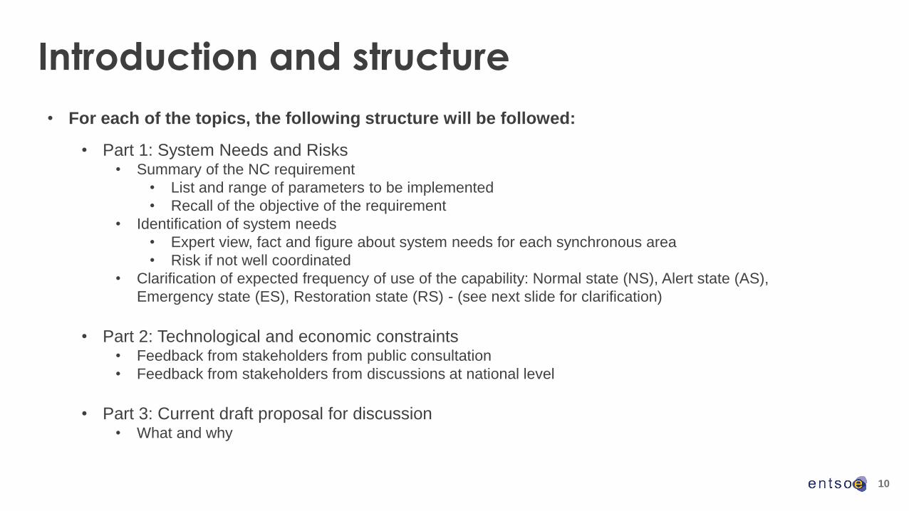
• For each of the topics, the following structure will be followed:
• Part 1: System Needs and Risks• Summary of the NC requirement
• List and range of parameters to be implemented
• Recall of the objective of the requirement
• Identification of system needs
• Expert view, fact and figure about system needs for each synchronous area
• Risk if not well coordinated
• Clarification of expected frequency of use of the capability: Normal state (NS), Alert state (AS),
Emergency state (ES), Restoration state (RS) - (see next slide for clarification)
• Part 2: Technological and economic constraints• Feedback from stakeholders from public consultation
• Feedback from stakeholders from discussions at national level
• Part 3: Current draft proposal for discussion• What and why

11
Introduction and structureN
C R
fG,
NC
DC
C, N
C H
VD
C
Normal state
Alert state
Restoration
stateEmergency state
Blackout
state
NS: The system is within operational security
limits in the N-situation and after the occurrence
of any contingency from the contingency list,
taking into account the effect of the available
remedial actions.
AS: A contingency from the contingency
list has been detected and in case of its
occurrence the available remedial actions
are not sufficient to keep the normal state.
Frequency meets certain criteria
More than 20% reduction of reserve
capacity for longer than 30 minutes
without means to compensate in real-time
system operation
ES: One or more operational security limits are
violated
Frequency does not meet the criteria for Normal and
Alert state
At least one measure of the TSO's system defence
plan is activated
Failure in the functioning of critical tools, means and
facilities, resulting in the unavailability of those tools,
means and facilities for longer than 30 minutes
BS: The operation of part or all of the transmission system is terminated
Loss of more 50% of demand in concerned TSO's control area
Total absence of voltage for at least three minutes in the TSO's control
area
RS: Objective of all activities in the
transmission system is to re-establish the
system operation and maintain operational
security.
The TSO has started to activate measures
of its restoration plan
SO
GL
NC
ER

12
Frequency Stability Requirements
• Frequency sensitive mode (FSM)
• Limited Frequency Sensitive Mode – Overfrequency (LFSM-O)
• Limited Frequency Sensitive Mode – Underfrequency (LFSM-U)
• Frequency Ranges
• Rate of Change of Frequency (RoCoF) withstand capability
• Synthetic Inertia (SI) and Demand Response very fast Active Power Control (DR APC)
• Initial TSO’s and stakeholders’ view on
• Demand Response System Frequency Control (DR SFC)
• Frequency ranges of automatic connection and gradient of active power increase
• Auto reconnection after an incidental disconnection
• Admissible active power reduction at low frequencies

13
Frequency Sensitive Mode (FSM)

14
Frequency Sensitive Mode (FSM)
RfG requirement: Article 15(2)(d)
Part
1: syste
m n
eeds a
nd r
isks
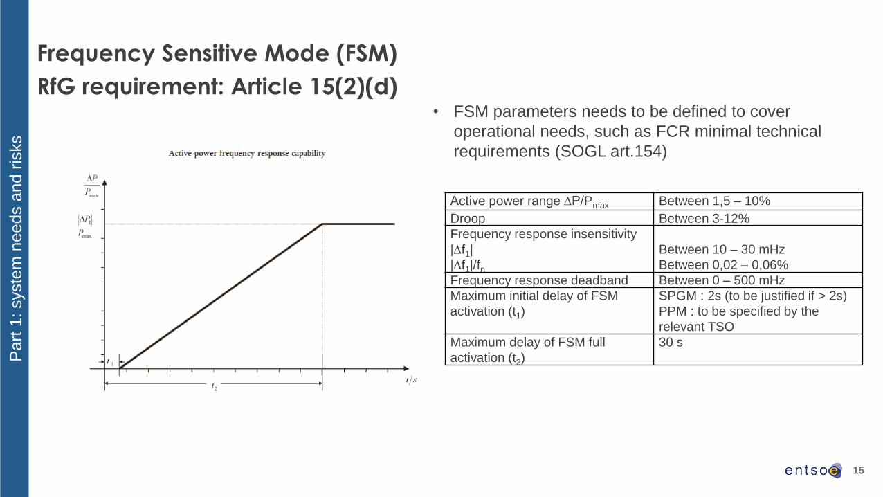
Active power range ∆P/Pmax Between 1,5 – 10%
Droop Between 3-12%
Frequency response insensitivity
|∆f1|
|∆f1|/fn
Between 10 – 30 mHz
Between 0,02 – 0,06%
Frequency response deadband Between 0 – 500 mHz
Maximum initial delay of FSM
activation (t1)
SPGM : 2s (to be justified if > 2s)
PPM : to be specified by the
relevant TSO
Maximum delay of FSM full
activation (t2)
30 s
• FSM is to be activated, when the system is in normal
state to ensure load-frequency control and restore the
frequency after a small frequency deviation.
• After a disturbance like the reference incident, FSM
contribute to stabilize the system in order to return to
normal state.
15
Frequency Sensitive Mode (FSM)
RfG requirement: Article 15(2)(d)
Part
1: syste
m n
eeds a
nd r
isks
Active power range ∆P/Pmax Between 1,5 – 10%
Droop Between 3-12%
Frequency response insensitivity
|∆f1|
|∆f1|/fn
Between 10 – 30 mHz
Between 0,02 – 0,06%
Frequency response deadband Between 0 – 500 mHz
Maximum initial delay of FSM
activation (t1)
SPGM : 2s (to be justified if > 2s)
PPM : to be specified by the
relevant TSO
Maximum delay of FSM full
activation (t2)
30 s
• FSM parameters needs to be defined to cover
operational needs, such as FCR minimal technical
requirements (SOGL art.154)
16
Frequency Sensitive Mode (FSM)
stakeholder feedback on technical capabilities
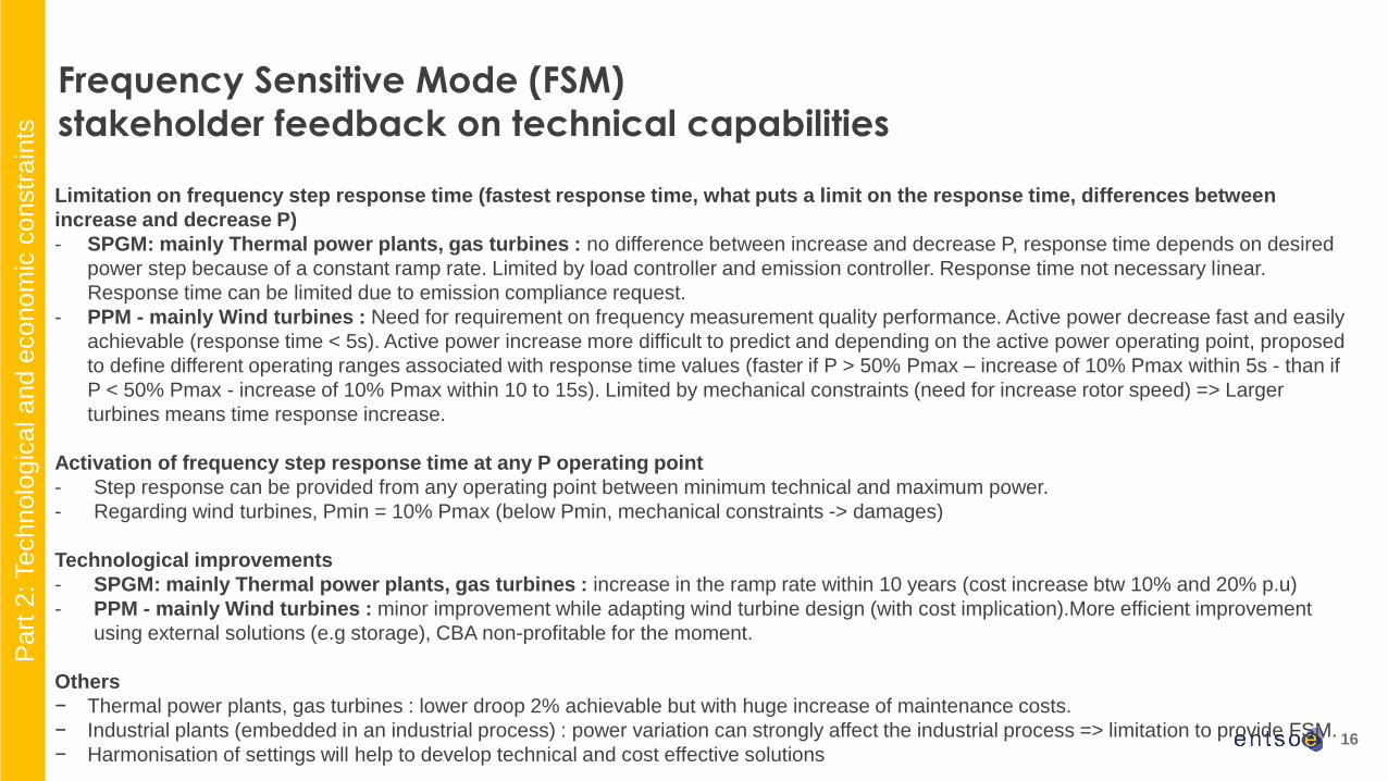
Limitation on frequency step response time (fastest response time, what puts a limit on the response time, differences between
increase and decrease P)
- SPGM: mainly Thermal power plants, gas turbines : no difference between increase and decrease P, response time depends on desired
power step because of a constant ramp rate. Limited by load controller and emission controller. Response time not necessary linear.
Response time can be limited due to emission compliance request.
- PPM - mainly Wind turbines : Need for requirement on frequency measurement quality performance. Active power decrease fast and easily
achievable (response time < 5s). Active power increase more difficult to predict and depending on the active power operating point, proposed
to define different operating ranges associated with response time values (faster if P > 50% Pmax – increase of 10% Pmax within 5s - than if
P < 50% Pmax - increase of 10% Pmax within 10 to 15s). Limited by mechanical constraints (need for increase rotor speed) => Larger
turbines means time response increase.
Activation of frequency step response time at any P operating point
- Step response can be provided from any operating point between minimum technical and maximum power.
- Regarding wind turbines, Pmin = 10% Pmax (below Pmin, mechanical constraints -> damages)
Technological improvements
- SPGM: mainly Thermal power plants, gas turbines : increase in the ramp rate within 10 years (cost increase btw 10% and 20% p.u)
- PPM - mainly Wind turbines : minor improvement while adapting wind turbine design (with cost implication).More efficient improvement
using external solutions (e.g storage), CBA non-profitable for the moment.
Others
− Thermal power plants, gas turbines : lower droop 2% achievable but with huge increase of maintenance costs.
− Industrial plants (embedded in an industrial process) : power variation can strongly affect the industrial process => limitation to provide FSM.
− Harmonisation of settings will help to develop technical and cost effective solutions
Part
2: Technolo
gic
al a
nd e
conom
ic c
onstr
ain
ts
17
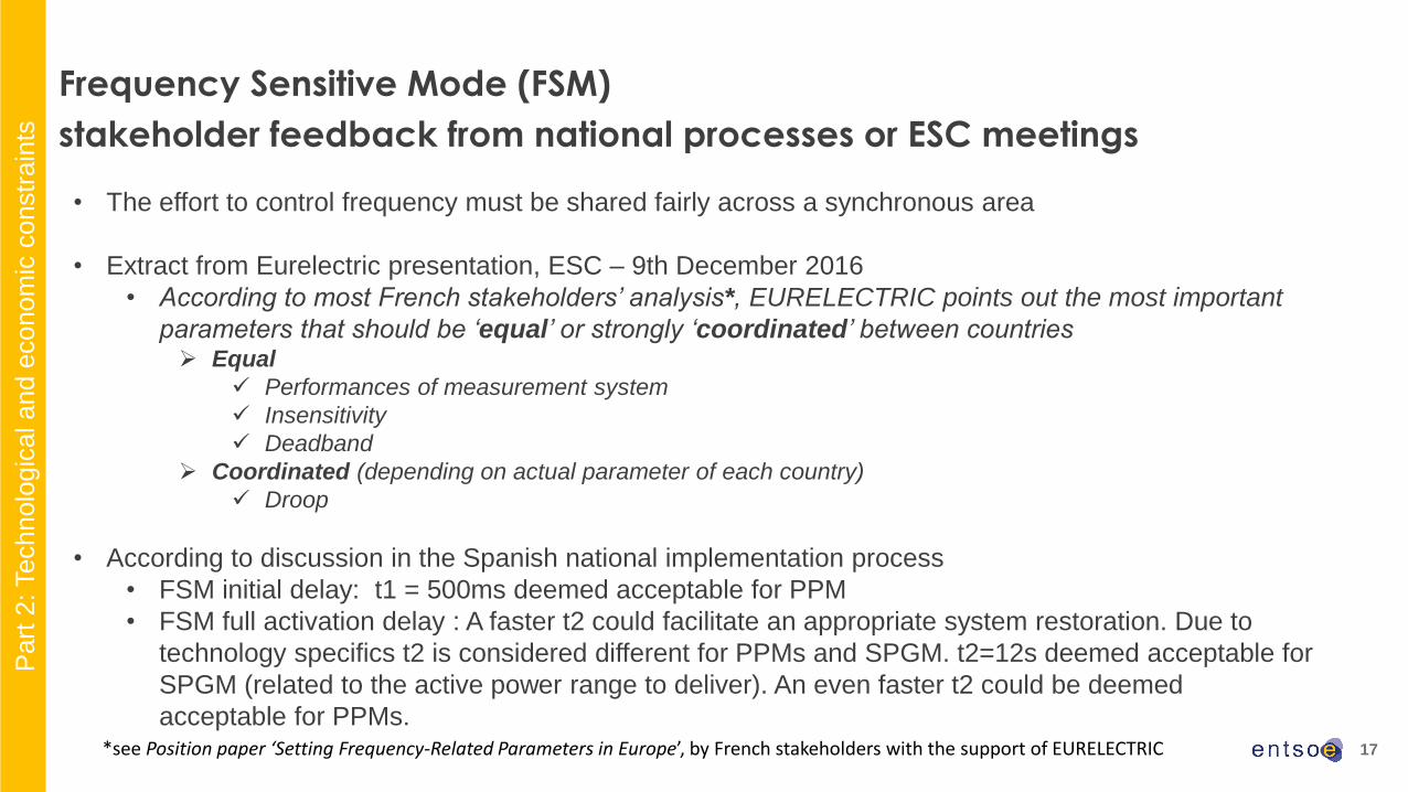
• The effort to control frequency must be shared fairly across a synchronous area
• Extract from Eurelectric presentation, ESC – 9th December 2016
• According to most French stakeholders’ analysis*, EURELECTRIC points out the most important
parameters that should be ‘equal’ or strongly ‘coordinated’ between countries➢ Equal
✓ Performances of measurement system
✓ Insensitivity
✓ Deadband
➢ Coordinated (depending on actual parameter of each country)
✓ Droop
• According to discussion in the Spanish national implementation process
• FSM initial delay: t1 = 500ms deemed acceptable for PPM
• FSM full activation delay : A faster t2 could facilitate an appropriate system restoration. Due to
technology specifics t2 is considered different for PPMs and SPGM. t2=12s deemed acceptable for
SPGM (related to the active power range to deliver). An even faster t2 could be deemed
acceptable for PPMs.
Frequency Sensitive Mode (FSM)
stakeholder feedback from national processes or ESC meetings
Part
2: Technolo
gic
al a
nd e
conom
ic c
onstr
ain
ts
*see Position paper ‘Setting Frequency-Related Parameters in Europe’, by French stakeholders with the support of EURELECTRIC

18
Frequency Sensitive Mode (FSM)
proposed parameters according to RfG Article 15(2)(d)
Parameters Proposal Comments
Active power range
related to maximum
capacity
|∆P1| / Pmax
Each TSO shall propose a value, which shall be understood
as a minimum technical requirement to ensure that FCR
part will be covered by C & D units in the country / TSO
control area.
Compliance to be tested against the chosen value.
To identify and quantify critical future scenarios with
low instantaneous penetration of C & D units
Droop s1 Adjustable droop to cover the active power range |∆P1| /
Pmax to be uniformly activated over the maximum
admissible frequency deviation for FCR.
To be calculated to be able to increase/decrease
power from |DP1| / Pmax for a FCR full activation
frequency deviation
Typical values : 4-5%
FSM requirements shall ensure that technical capabilities and, where applicable, initial settings of
parameters are available to cover operational needs, such as FCR minimal technical requirements
(SO GL, Art 154).
• Methodology to define active power range and associated droop :
Part
3: C
urr
ent
dra
ft p
roposal fo
r dis
cussio
n

19• ENTSO-E experts are working to recommend a minimum frequency measurement quality performance.
Frequency Sensitive Mode (FSM)
proposed parameters according to RfG Article 15(2)(d)
Parameters Proposal Comments
Frequency response
insensitivity
|∆fi| / fn ≤ 0,02% Ensure compliance with FCR requirements
Note : insensitivity is not accuracy|∆fi| ≤ 10 mHz
Frequency response
deadband
Adjustable value in the range of 0 – 500 mHz
Default values :
• CE, Nordic, GB, IE : 0 mHz
• Baltics : n/a
Ensure compliance with FCR requirements.
Setting a large deadband may be used to “deactivate” FSM under
normal operating conditions but shall not impair LFSM-O/-U function
Initial delay t1 ≤ 2s for SPGM
≤ 500 ms for PPM
To use widest possible technical capability of the power-generating
module
Response activation
(full activation) t2
CE, Nordic : 30s Default value proposed refers to normal operating conditions across CE. In case
of forming local islands accidentally, a faster t2 could be requested by the TSO
with the purpose of facilitating an appropriate system restoration. Therefore the
generator FSM control must be designed to allow a faster response in case of
local needs, taking into consideration technology specifics.
GB 10s
IE/NI 15s
Part
3: C
urr
ent
dra
ft p
roposal fo
r dis
cussio
n
• Proposed settings for parameters

20
Limited Frequency Sensitive Mode – Overfrequency
(LFSM-O)
21
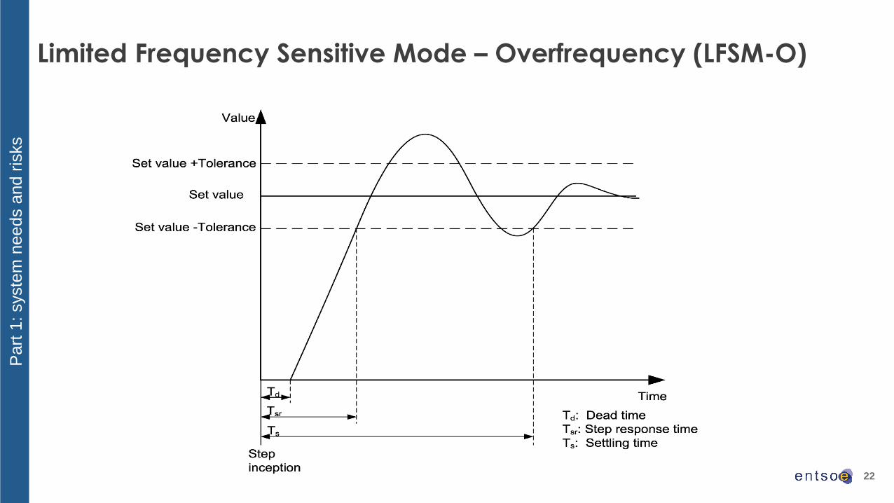
Limited Frequency Sensitive Mode – Overfrequency (LFSM-O)
RfG requirement: Article 13(2)
Part
1: syste
m n
eeds a
nd r
isks
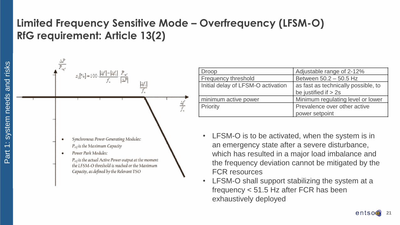
Droop Adjustable range of 2-12%
Frequency threshold Between 50.2 – 50.5 Hz
Initial delay of LFSM-O activation as fast as technically possible, to
be justified if > 2s
minimum active power Minimum regulating level or lower
Priority Prevalence over other active
power setpoint
• LFSM-O is to be activated, when the system is in
an emergency state after a severe disturbance,
which has resulted in a major load imbalance and
the frequency deviation cannot be mitigated by the
FCR resources
• LFSM-O shall support stabilizing the system at a
frequency < 51.5 Hz after FCR has been
exhaustively deployed
22
Limited Frequency Sensitive Mode – Overfrequency (LFSM-O)
Part
1: syste
m n
eeds a
nd r
isks
23
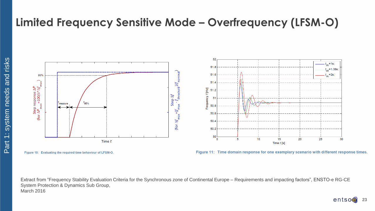
Limited Frequency Sensitive Mode – Overfrequency (LFSM-O)
Part
1: syste
m n
eeds a
nd r
isks
Extract from “Frequency Stability Evaluation Criteria for the Synchronous zone of Continental Europe – Requirements and impacting factors”, ENSTO-e RG-CE
System Protection & Dynamics Sub Group,
March 2016

24
Limited Frequency Sensitive Mode – Overfrequency (LFSM-O)
RfG requirement (II): Article 13(2)
Part
1: syste
m n
eeds a
nd r
isks
Extract from “Frequency Stability
Evaluation Criteria for the Synchronous
zone of Continental Europe –
Requirements and impacting factors”,
ENSTO-e RG-CE System Protection &
Dynamics Sub Group,
March 2016

25
Limited Frequency Sensitive Mode – Overfrequency (LFSM-O)
stakeholder feedback on consultation on technical capabilities
Feasibility of an adjustable droop range and associated costs
- adjustable droop is technically feasible is not a significant cost issue
- a low droop with more frequency sensitive responses could lead to increased maintenance costs
Limitation on frequency step response time (fastest response time, what puts a limit on the response time, differences between
increase and decrease P)
- PPM - wind turbines : Need for a common frequency measurement method. Active power decrease fast and easily achievable
(response time < 5s). Active power increase more difficult to predict and depending on the active power operating point, proposed to
define different operating ranges associated with response time values (faster if P > 50% Pmax – increase of 2-5% Pmax/s - than if P <
50% Pmax - increase of 1% Pmax/s). Limited by mechanical constraints (need for increase rotor speed) => Larger turbines means time
response increase.
- SPGM - gas turbines and combustion engines: response time depends on desired power step because of a constant ramp rate.
Limited by load controller and emission controller. Fastest response for combustion engines: 30s.
Activation of frequency step response time at any P operating point
- PPM - wind turbines : Wind turbines not controllable below 10%Pmax.
- SPGM - gas turbines and combustion engines: from any point between minimum operating level and Pmax
Technological improvements
- PPM - wind turbines : minor improvements in turbine technology; use of battery or other storage technologies technically feasible at
significant costs
- SPGM - gas turbines : products are continuously improved, increased performance through harmonization of settings response times
of 5s are conceivable, cost implications difficult to assess
- SPGM - combustion engines: double the ramp rate at 10-20% cost increase
Part
2: Technolo
gic
al a
nd e
conom
ic c
onstr
ain
ts
26
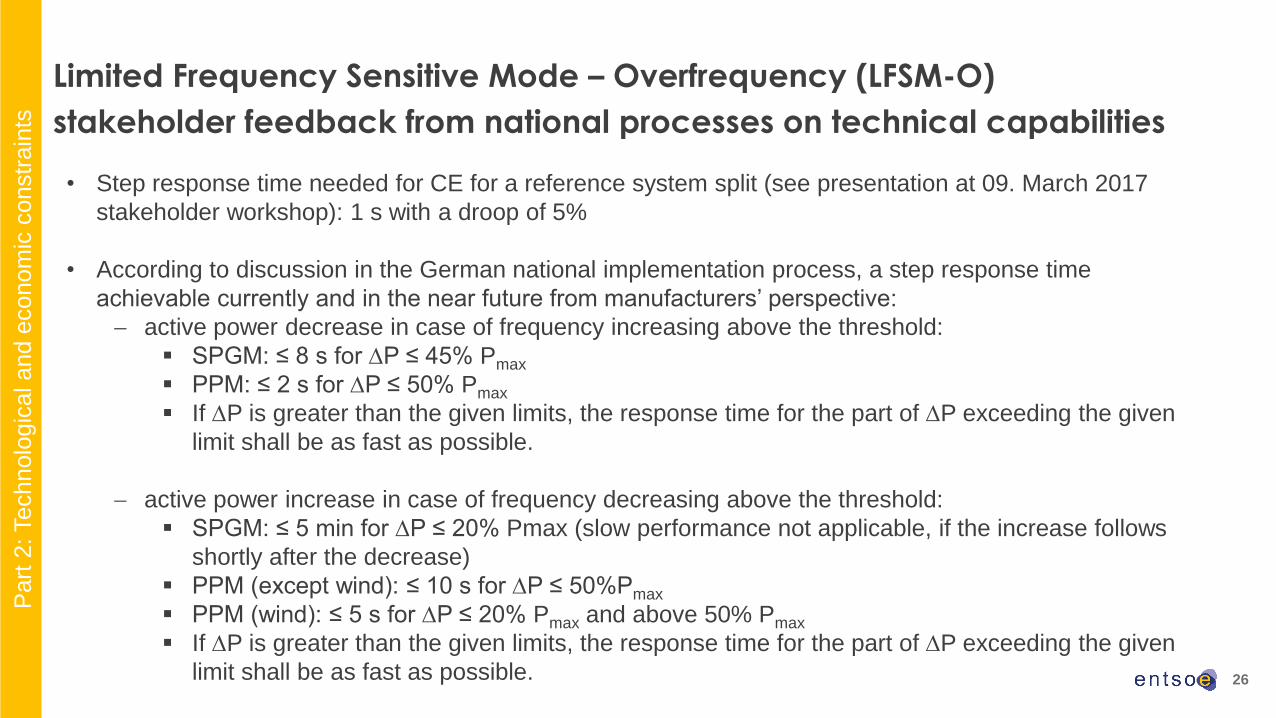
• Step response time needed for CE for a reference system split (see presentation at 09. March 2017
stakeholder workshop): 1 s with a droop of 5%
• According to discussion in the German national implementation process, a step response time
achievable currently and in the near future from manufacturers’ perspective:
active power decrease in case of frequency increasing above the threshold:
▪ SPGM: ≤ 8 s for P ≤ 45% Pmax
▪ PPM: ≤ 2 s for P ≤ 50% Pmax
▪ If P is greater than the given limits, the response time for the part of P exceeding the given
limit shall be as fast as possible.
active power increase in case of frequency decreasing above the threshold:
▪ SPGM: ≤ 5 min for P ≤ 20% Pmax (slow performance not applicable, if the increase follows
shortly after the decrease)
▪ PPM (except wind): ≤ 10 s for P ≤ 50%Pmax
▪ PPM (wind): ≤ 5 s for P ≤ 20% Pmax and above 50% Pmax
▪ If P is greater than the given limits, the response time for the part of P exceeding the given
limit shall be as fast as possible.
Limited Frequency Sensitive Mode – Overfrequency (LFSM-O)
stakeholder feedback from national processes on technical capabilities
Part
2: Technolo
gic
al a
nd e
conom
ic c
onstr
ain
ts
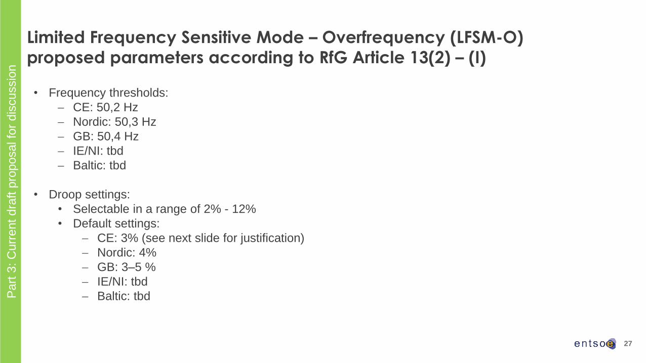
27
• Frequency thresholds:
CE: 50,2 Hz
Nordic: 50,3 Hz
GB: 50,4 Hz
IE/NI: tbd
Baltic: tbd
• Droop settings:
• Selectable in a range of 2% - 12%
• Default settings:
CE: 3% (see next slide for justification)
Nordic: 4%
GB: 3–5 %
IE/NI: tbd
Baltic: tbd
Limited Frequency Sensitive Mode – Overfrequency (LFSM-O)
proposed parameters according to RfG Article 13(2) – (I)
Part
3: C
urr
ent
dra
ft p
roposal fo
r dis
cussio
n

28
• Step response time needed for CE for a reference system split (see presentation at 09. March 2017
stakeholder workshop): 1 s with a droop of 5% (or 2s with a droop of 3%)
• Response time proposal for CE taking into consideration both system needs and plant capabilities:
PPM: droop of 3% and response time of 2 s (active power decrease) or 5 s (active power increase)
SPGM: droop and response time as fast as currently achievable from manufacturers’ perspective
with the selected design (same values for active power increase as for decrease)
• First swing overshoot to be as small as possible and ≤ 10% of the step change
• Settling time:
active power decrease in case of frequency increasing above the threshold:
▪ SPGM: ≤ 30 s
▪ PPM: ≤ 20 s
active power increase in case of frequency decreasing above the threshold:
▪ SPGM: ≤ 6 min (slow performance not applicable, if the increase follows shortly (within a few
seconds) after the decrease)
▪ PPM: ≤ 30 s
Limited Frequency Sensitive Mode – Overfrequency (LFSM-O)
proposed parameters in addition to RfG Article 13(2) – (II)
Part
3: C
urr
ent
dra
ft p
roposal fo
r dis
cussio
n
29
Limited Frequency Sensitive Mode – Underfrequency
(LFSM-U)
30
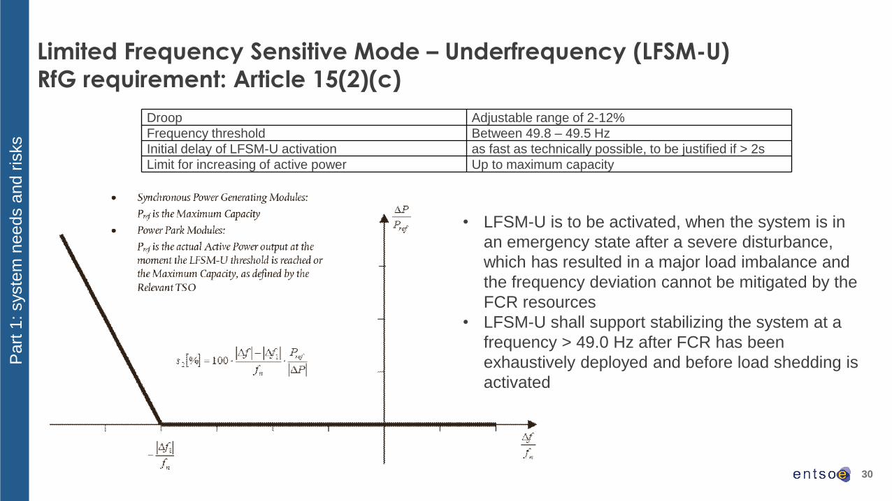
Limited Frequency Sensitive Mode – Underfrequency (LFSM-U)
RfG requirement: Article 15(2)(c)
Droop Adjustable range of 2-12%
Frequency threshold Between 49.8 – 49.5 Hz
Initial delay of LFSM-U activation as fast as technically possible, to be justified if > 2s
Limit for increasing of active power Up to maximum capacity
Part
1: syste
m n
eeds a
nd r
isks
• LFSM-U is to be activated, when the system is in
an emergency state after a severe disturbance,
which has resulted in a major load imbalance and
the frequency deviation cannot be mitigated by the
FCR resources
• LFSM-U shall support stabilizing the system at a
frequency > 49.0 Hz after FCR has been
exhaustively deployed and before load shedding is
activated

31
Limited Frequency Sensitive Mode – Underfrequency (LFSM-U)
Part
1: syste
m n
eeds a
nd r
isks

32
Q1 Limitation on frequency step response time (fastest response time, what puts a limit on the response time, differences between
increase and decrease P)− SPGM - gas turbines and combustion engines: The parameters according NC RfG can be followed. Response time is limited by the load controller and
emission controller. Settling time depends on extent frequency change (now: from 0.56%/s to 1.11%/s in each direction up and down). Limitation is given by
ambient condition (temperature), emission compliance or generation in CHP cycles and by inherent thermo/mechanical inertia
− PPM - wind turbines : The only option to underfrequency response is operating bellow MPP (maximal power point) or using built-in battery storage. Response
time depends on rotor speed (higher wind speed --> faster P increase)
Q2 Activation of frequency step response time at any P operating point− SPGM - gas turbines and combustion engines: Step response is achievable in whole active power range. Response time is given by constant ramp rate.
Response time is not necessarily linear (depends on f deviation, RoCoF) proportional response
− PPM - wind turbines : Activation of frequency step response time above 10% of Pn is without limitation.
Q3 Limiting factor of LFSM-U activation− SPGM - gas turbines and combustion engines: Limiting factors: engine overload and ramp rates limits (engine running in CHP). Maximum step response time
could be limited by emission compliance. Time response is limited by slow inertia of conventional boilers in sliding pressure mode
− PPM - wind turbines : At very low active power (<20% of PRATED) the synthetic inertia is not available (not enough kinetic energy). Activation depends on
current P output (lower levels slower; higher levels faster) i.e. P>50%Pn ∆P of 10% in 5s and P<50%Pn ∆P of 10% in 10-15s.
Q4 Technological improvements− SPGM - gas turbines and combustion engines: Optimization of the fuel mixture-generation system (but it could cause a worse efficiency) and by optimization
of settling time (but need to specify that such an event only happens a few times in the lifetime) and upgrade of gas admission system, additional actuators,
modified turbocharger. Increase of ramp rate up to 3%/s (but this could lead to increase of cost up to 20% of p.u.)
− PPM - wind turbines : Use battery storages -> ensure a synthetic inertia
Limited Frequency Sensitive Mode – Underfrequency (LFSM-U)
stakeholder feedback on technical capabilities
Part
2: Technolo
gic
al a
nd e
conom
ic c
onstr
ain
ts
33
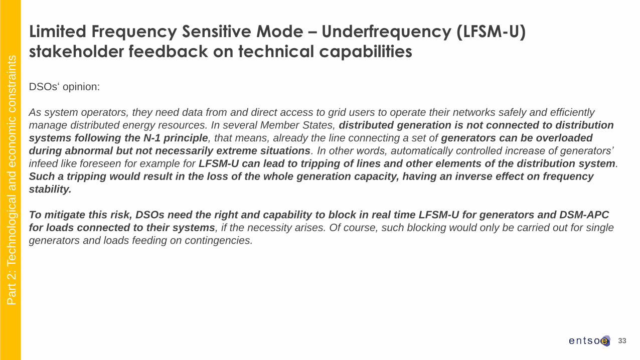
DSOs‘ opinion:
As system operators, they need data from and direct access to grid users to operate their networks safely and efficiently
manage distributed energy resources. In several Member States, distributed generation is not connected to distribution
systems following the N-1 principle, that means, already the line connecting a set of generators can be overloaded
during abnormal but not necessarily extreme situations. In other words, automatically controlled increase of generators’
infeed like foreseen for example for LFSM-U can lead to tripping of lines and other elements of the distribution system.
Such a tripping would result in the loss of the whole generation capacity, having an inverse effect on frequency
stability.
To mitigate this risk, DSOs need the right and capability to block in real time LFSM-U for generators and DSM-APC
for loads connected to their systems, if the necessity arises. Of course, such blocking would only be carried out for single
generators and loads feeding on contingencies.
Limited Frequency Sensitive Mode – Underfrequency (LFSM-U)
stakeholder feedback on technical capabilities
Part
2: Technolo
gic
al a
nd e
conom
ic c
onstr
ain
ts
34
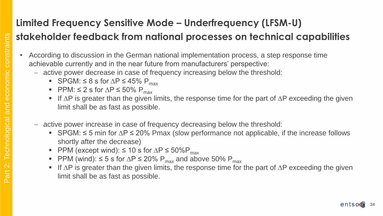
• According to discussion in the German national implementation process, a step response time
achievable currently and in the near future from manufacturers’ perspective:
active power decrease in case of frequency increasing below the threshold:
▪ SPGM: ≤ 8 s for P ≤ 45% Pmax
▪ PPM: ≤ 2 s for P ≤ 50% Pmax
▪ If P is greater than the given limits, the response time for the part of P exceeding the given
limit shall be as fast as possible.
active power increase in case of frequency decreasing below the threshold:
▪ SPGM: ≤ 5 min for P ≤ 20% Pmax (slow performance not applicable, if the increase follows
shortly after the decrease)
▪ PPM (except wind): ≤ 10 s for P ≤ 50%Pmax
▪ PPM (wind): ≤ 5 s for P ≤ 20% Pmax and above 50% Pmax
▪ If P is greater than the given limits, the response time for the part of P exceeding the given
limit shall be as fast as possible.
Limited Frequency Sensitive Mode – Underfrequency (LFSM-U)
stakeholder feedback from national processes on technical capabilities
Part
2: Technolo
gic
al a
nd e
conom
ic c
onstr
ain
ts

35
• Frequency thresholds:
CE: 49,8 Hz
Nordic: 49,5 Hz
GB: 49,5 Hz
IE/NI: tbd
Baltic: tbd
• Droop settings:
• Selectable in a range of 2% - 12%
• Default settings: ≤ FSM settings
Limited Frequency Sensitive Mode – Underfrequency (LFSM-U)
proposed parameters according to Article 15(2)(c)
Part
3: C
urr
ent
dra
ft p
roposal fo
r dis
cussio
n
36
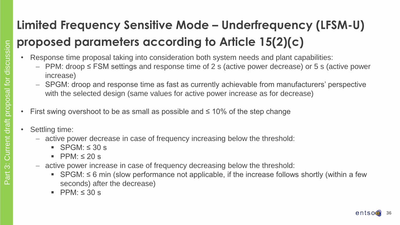
• Response time proposal taking into consideration both system needs and plant capabilities:
PPM: droop ≤ FSM settings and response time of 2 s (active power decrease) or 5 s (active power
increase)
SPGM: droop and response time as fast as currently achievable from manufacturers’ perspective
with the selected design (same values for active power increase as for decrease)
• First swing overshoot to be as small as possible and ≤ 10% of the step change
• Settling time:
active power decrease in case of frequency increasing below the threshold:
▪ SPGM: ≤ 30 s
▪ PPM: ≤ 20 s
active power increase in case of frequency decreasing below the threshold:
▪ SPGM: ≤ 6 min (slow performance not applicable, if the increase follows shortly (within a few
seconds) after the decrease)
▪ PPM: ≤ 30 s
Limited Frequency Sensitive Mode – Underfrequency (LFSM-U)
proposed parameters according to Article 15(2)(c)
Part
3: C
urr
ent
dra
ft p
roposal fo
r dis
cussio
n

37
Frequency Ranges
38
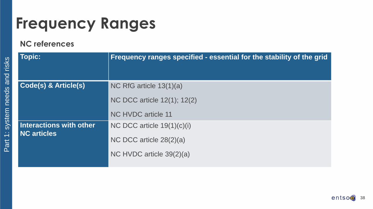
Frequency Ranges
Topic: Frequency ranges specified - essential for the stability of the grid
Code(s) & Article(s) NC RfG article 13(1)(a)
NC DCC article 12(1); 12(2)
NC HVDC article 11
Interactions with other
NC articlesNC DCC article 19(1)(c)(i)
NC DCC article 28(2)(a)
NC HVDC article 39(2)(a)
NC references
Part
1: syste
m n
eeds a
nd r
isks
39
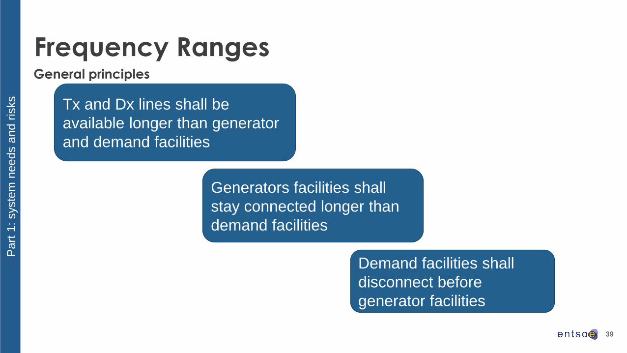
Frequency RangesGeneral principles
Part
1: syste
m n
eeds a
nd r
isks
Tx and Dx lines shall be
available longer than generator
and demand facilities
Generators facilities shall
stay connected longer than
demand facilities
Demand facilities shall
disconnect before
generator facilities
40
Frequency Ranges
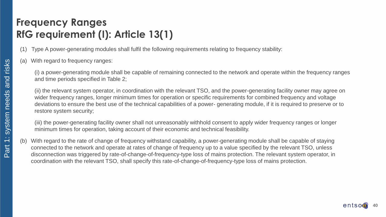
RfG requirement (I): Article 13(1)
(1) Type A power-generating modules shall fulfil the following requirements relating to frequency stability:
(a) With regard to frequency ranges:
(i) a power-generating module shall be capable of remaining connected to the network and operate within the frequency ranges
and time periods specified in Table 2;
(ii) the relevant system operator, in coordination with the relevant TSO, and the power-generating facility owner may agree on
wider frequency ranges, longer minimum times for operation or specific requirements for combined frequency and voltage
deviations to ensure the best use of the technical capabilities of a power- generating module, if it is required to preserve or to
restore system security;
(iii) the power-generating facility owner shall not unreasonably withhold consent to apply wider frequency ranges or longer
minimum times for operation, taking account of their economic and technical feasibility.
(b) With regard to the rate of change of frequency withstand capability, a power-generating module shall be capable of staying
connected to the network and operate at rates of change of frequency up to a value specified by the relevant TSO, unless
disconnection was triggered by rate-of-change-of-frequency-type loss of mains protection. The relevant system operator, in
coordination with the relevant TSO, shall specify this rate-of-change-of-frequency-type loss of mains protection.
Part
1: syste
m n
eeds a
nd r
isks

41
Frequency Ranges
RfG requirement (II): Article 13(1)
Ranges Synchronous area
GB IE / NI Baltic Nordic CE47,0 Hz-47,5 Hz 20 seconds ------------------------ ------------------------ ------------------------ ------------------------
47,5 Hz-48,5 Hz 90 minutes 90 minutes To be specified by
each TSO, but not
less than 30 minutes
30 minutes To be specified by
each TSO, but not
less than 30 minutes
48,5 Hz-49,0 Hz To be specified by
each TSO, but not
less than 90 minutes
To be specified by
each TSO, but not
less than 90 minutes
To be specified by
each TSO, but not
less than the period
for 47,5 Hz-48,5 Hz
To be specified by
each TSO, but not
less than 30 minutes
To be specified by
each TSO, but not
less than the period
for 47,5 Hz-48,5 Hz
49,0 Hz-51,0 Hz Unlimited Unlimited Unlimited Unlimited Unlimited
51,0 Hz-51,5 Hz 90 minutes 90 minutes To be specified by
each TSO, but not
less than 30 minutes
30 minutes 30 minutes
51,5 Hz-52,0 Hz 15 minutes ------------------------ ------------------------ ------------------------ ------------------------
Part
1: syste
m n
eeds a
nd r
isks
42
- None received until now.
Frequency ranges
stakeholder feedback on technical capabilities
Part
2: Technolo
gic
al a
nd e
conom
ic c
onstr
ain
ts

43
Frequency Ranges
proposed parameters according to RfG Article 13(1) (1/5)
Ranges Synchronous area
CE Proposal of WG CNC
47,0 Hz-47,5 Hz ------------------------ ------------------------
47,5 Hz-48,5 Hz To be specified by each TSO, but not less
than 30 minutes
30 minutes, but longer minimum time
periods may be required for countries,
which are exposed to a higher risk of
islanding (e.g. peninsular area) to allow for
an extended period of time for system
restoration
48,5 Hz-49,0 Hz To be specified by each TSO, but not less
than the period for 47,5 Hz-48,5 Hz
30 minutes, but longer minimum time
periods may be required for countries,
which are exposed to a higher risk of
islanding (e.g. peninsular area) to allow for
an extended period of time for system
restoration
49,0 Hz-51,0 Hz Unlimited Unlimited
51,0 Hz-51,5 Hz 30 minutes 30 minutes
51,5 Hz-52,0 Hz ------------------------ ------------------------
Part
3: C
urr
ent
dra
ft p
roposal fo
r dis
cussio
n

44
Frequency Ranges
proposed parameters according to RfG Article 13(1) (2/5)
Ranges Synchronous area
Nordic Proposal of WG CNC47,0 Hz-47,5 Hz ------------------------ ------------------------
47,5 Hz-48,5 Hz 30 minutes 30 minutes
48,5 Hz-49,0 Hz To be specified by each TSO, but not less
than 30 minutes
30 minutes
49,0 Hz-51,0 Hz Unlimited Unlimited
51,0 Hz-51,5 Hz 30 minutes 30 minutes
51,5 Hz-52,0 Hz ------------------------ ------------------------Part
3: C
urr
ent
dra
ft p
roposal fo
r dis
cussio
n

45
Frequency Ranges
proposed parameters according to RfG Article 13(1) (3/5)
Ranges Synchronous area
Baltic Proposal of WG CNC
47,0 Hz-47,5 Hz ------------------------ ------------------------
47,5 Hz-48,5 Hz To be specified by each TSO, but not less
than 30 minutes
30 minutes
48,5 Hz-49,0 Hz To be specified by each TSO, but not less
than the period for 47,5 Hz-48,5 Hz
To be specified by each TSO, but not less
than 30 minutes
49,0 Hz-51,0 Hz Unlimited Unlimited
51,0 Hz-51,5 Hz To be specified by each TSO, but not less
than 30 minutes
30 minutes
51,5 Hz-52,0 Hz ------------------------ ------------------------Part
3: C
urr
ent
dra
ft p
roposal fo
r dis
cussio
n

46
Frequency Ranges
proposed parameters according to RfG Article 13(1) (4/5)
Ranges Synchronous area
IE /NI Proposal of WG CNC
47,0 Hz-47,5 Hz ------------------------ ---------------------
47,5 Hz-48,5 Hz 90 minutes
90 minutes
48,5 Hz-49,0 Hz To be specified by each TSO, but not less
than 90 minutes 90 minutes
49,0 Hz-51,0 Hz UnlimitedUnlimited
51,0 Hz-51,5 Hz 90 minutes 90 minutes
51,5 Hz-52,0 Hz ------------------------ ---------------------
Part
3: C
urr
ent
dra
ft p
roposal fo
r dis
cussio
n

47
Ranges Synchronous area
GB Proposal of WG CNC
47,0 Hz-47,5 Hz 20 seconds 20 seconds
47,5 Hz-48,5 Hz 90 minutes90 minutes
48,5 Hz-49,0 Hz To be specified by each TSO, but not less
than 90 minutes 90 minutes
49,0 Hz-51,0 Hz UnlimitedUnlimited
51,0 Hz-51,5 Hz 90 minutes
90 minutes
51,5 Hz-52,0 Hz 15 minutes 15 minutes
Part
3: C
urr
ent
dra
ft p
roposal fo
r dis
cussio
n
Frequency Ranges
proposed parameters according to RfG Article 13(1) (5/5)
48
Rate of Change of Frequency (RoCoF)
Withstand Capability
49
Rate of Change of Frequency (RoCoF) Withstand Capability
RfG: Article 13(1)(b); DCC: Article 28(2)(k); HVDC: Articles 12, 39(3)
The requirement aims at ensuring that power generating modules (NC RfG), demand units offering Demand Response (DR) services
(DCC), HVDC systems and DC-connected power park modules shall not disconnect from the network up to a maximum rate of change
of frequency (df/dt).
While defining the RoCoF withstand capability, each TSO should take the following concerns and issues into account:
➢ Transition from existing to future generation mix, in particular instantaneous penetration of non-synchronous generation (PPMs)
➢ Disconnection of users due to own instability (e.g. pole slip)
➢ High df/dt may reduce generators’ lifetime (physical damages to the shaft)
➢ Different users have different inherent capabilities (e.g. wind turbines can easily withstand RoCoFs up to 4Hz/s)
➢ The measurement time window and technique for verification of compliance
Furthermore, the TSO may conduct following studies before implementing the requirement:
✓ Possibility of requiring dissimilar requirements for different technologies (e.g. thermal power plant and power electronic connected
modules)
✓ Whether to define a single RoCoF value or set of frequency-against-time profiles
The resulting RoCoF withstand capability value will be an important input to calculate the essential minimum inertia (provided by the
synchronous PGM with inherent inertia and by PPMs with synthetic inertia) for system stability in case of outage or system split, incl.
asynchronous operation of control block. Therefore there is a direct link between RoCoF and inertia related requirements.
Part
1: syste
m n
eeds a
nd r
isks

50
Rate of Change of Frequency (RoCoF) Withstand Capability
RfG: Article 13(1)(b); DCC: Article 28(2)(k); HVDC: Articles 12, 39(3)
Part
1: syste
m n
eeds a
nd r
isks
Extract from “Frequency Stability Evaluation Criteria for
the Synchronous zone of Continental Europe –
Requirements and impacting factors”, ENSTO-e RG-
CE System Protection & Dynamics Sub Group,
March 2016
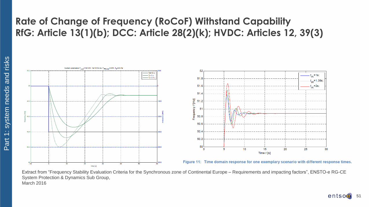
51
Rate of Change of Frequency (RoCoF) Withstand Capability
RfG: Article 13(1)(b); DCC: Article 28(2)(k); HVDC: Articles 12, 39(3)
Part
1: syste
m n
eeds a
nd r
isks
Extract from “Frequency Stability Evaluation Criteria for the Synchronous zone of Continental Europe – Requirements and impacting factors”, ENSTO-e RG-CE
System Protection & Dynamics Sub Group,
March 2016

52
Rate of Change of Frequency (RoCoF) Withstand CapabilityOutcome of Consultation of Stakeholders on Guidance for Connection Code implementation of frequency related parameters
What is your assumed or calculated value for maximum df/dt withstand capability in your basic design?
• SPGM :
➢ GT can withstand 2.5 Hz/s with 100 ms (5 cycles @ 50 Hz) window
• PPM - Wind Farm mainly full converter
➢ 6Hz per second has been observed and runs stable. 4Hz/s we guarantee.
• PPM - Wind Farm mainly DFIG:
➢ 4Hz/s for current injection control mode (grid-forming control not yet investigated)
Important concerns /issues which are not mentioned in the previous slides:
SPGM
➢ rigidity of the connection point
➢ repetition of high df/dt can overstress both electrical and mechanical equipment
➢ the stability of controllers
➢ stability of the plant’s auxiliary machines
PPM - Wind Farm
➢ control instabilities
Part
2: Technolo
gic
al a
nd e
conom
ic c
onstr
ain
ts

53
Rate of Change of Frequency (RoCoF) Withstand CapabilityOutcome of Consultation of Stakeholders on Guidance for Connection Code implementation of frequency related parameters
Noteworthy comments:
None of the responding stakeholders use df/dt as an input to any protection for their plant (SPGM related stakeholders have indicated
that in some cases it is used along other inputs for split detection). Therefore, their main concern about high df/dt is the high risk of
instability and possible damages to their equipment.
The definition of RoCoF and measurement time window has also been a concern by the SPGM related stakeholders
• the RoCoF value shall be tied to other information, such as frequency versus time profile, measuring method (including
rolling average), operating condition (active power, PF) and grid status (grid topology, impedance, voltage profile) and possibly
different profiles for over-frequency and under-frequency.
• RoCoF stakes and df/dt capability have not been historically explicitly part of design requirement.
• Analysis to understand RoCoF stakes, study and verify could be of a minimum of 10% of plant CAPEX and can exponentially
increase depending on the outcome and the complexity of the system.
• This shall be considered a very conservative estimation, since costs can quickly increase even for the control and related
instrumentations and actuators are to be considered.
• If mechanical/electrical integrity (shaft line torsional fatigue…) or system stability (generator stability, excitation voltage surge,
compressor surge...) is involved, the cost could be tremendous and just put at stake the plant’s viability.
Part
2: Technolo
gic
al a
nd e
conom
ic c
onstr
ain
ts
54
Rate of Change of Frequency (RoCoF) Withstand Capability
frequency-against-time profiles
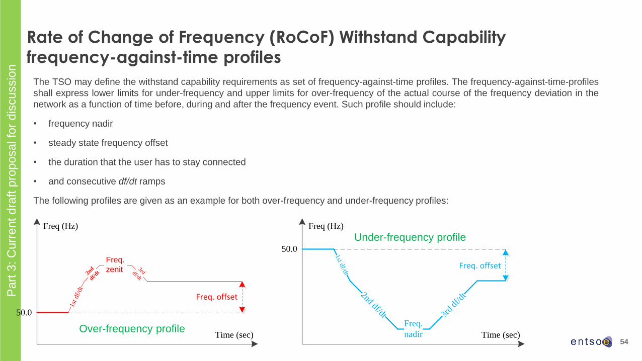
The TSO may define the withstand capability requirements as set of frequency-against-time profiles. The frequency-against-time-profiles
shall express lower limits for under-frequency and upper limits for over-frequency of the actual course of the frequency deviation in the
network as a function of time before, during and after the frequency event. Such profile should include:
• frequency nadir
• steady state frequency offset
• the duration that the user has to stay connected
• and consecutive df/dt ramps
The following profiles are given as an example for both over-frequency and under-frequency profiles:
Freq. offset
Freq (Hz)
Time (sec)
1st df/dt
2nd df/dt
Freq.
nadir
3rd
df/d
t
50.0
Over-frequency profile
Under-frequency profile
Part
3: C
urr
ent
dra
ft p
roposal fo
r dis
cussio
n
Freq. offset
1st df
/dt
Freq.
nadir 3rd df/dt2n
d
df/dt
Freq (Hz)
Time (sec)
50.0
Freq.
zenit
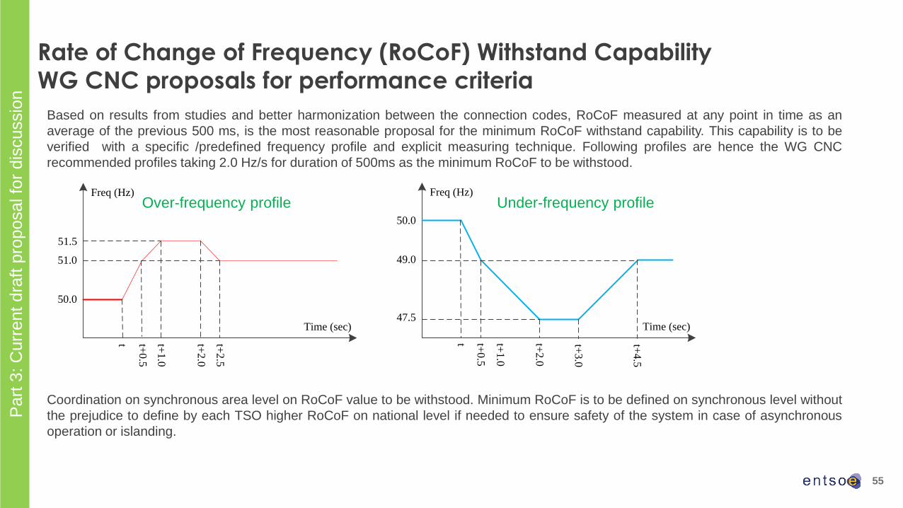
Based on results from studies and better harmonization between the connection codes, RoCoF measured at any point in time as an
average of the previous 500 ms, is the most reasonable proposal for the minimum RoCoF withstand capability. This capability is to be
verified with a specific /predefined frequency profile and explicit measuring technique. Following profiles are hence the WG CNC
recommended profiles taking 2.0 Hz/s for duration of 500ms as the minimum RoCoF to be withstood.
Coordination on synchronous area level on RoCoF value to be withstood. Minimum RoCoF is to be defined on synchronous level without
the prejudice to define by each TSO higher RoCoF on national level if needed to ensure safety of the system in case of asynchronous
operation or islanding.
Freq (Hz)
Time (sec)
50.0
49.0
47.5
t t+0
.5
t+2
.0
t+3
.0
t+4
.5
t+1
.0
Freq (Hz)
Time (sec)
50.0
51.0
51.5
t t+0.5
t+2.0
t+2.5
t+1.0
55
Rate of Change of Frequency (RoCoF) Withstand Capability
WG CNC proposals for performance criteria
Over-frequency profile Under-frequency profile
Part
3: C
urr
ent
dra
ft p
roposal fo
r dis
cussio
n

56
Synthetic Inertia (SI) and Demand Response very fast
Active Power Control (DR APC)

57
Synthetic Inertia & demand response (DR) very fast active power
control (APC).
NC RfG - Article 21.2(a): The relevant TSO shall have the right to specify that power park modules [of type
C and D] be capable of providing synthetic inertia during very fast frequency deviations.
NC HVDC - Article 14.1: If specified by a relevant TSO, an HVDC system shall be capable of providing
synthetic inertia in response to frequency changes, activated in low and/or high frequency regimes by
rapidly adjusting the active power injected to or withdrawn from the AC network in order to limit the rate of
change of frequency.
NC DCC – Article 30.1: The relevant TSO in coordination with the relevant system operator may agree
with a demand facility owner or a closed distribution system operator (CDSO) (including, but not restricted
to, through a third party) on a contract for the delivery of demand response very fast active power control.
Part
1: syste
m n
eeds a
nd r
isks

58
Minimum Inertia Contribution (from PGM, HVDC and DSR with very fast APC):
Based on
• System studies results for scenarios for horizon 2030 (see IGD HPoPEIPS)
• IGD recommended decision flow chart
Then, recommendation for national implementation of article NC RfG - Article 21.2(a) and NC HVDC -
Article 14.1:
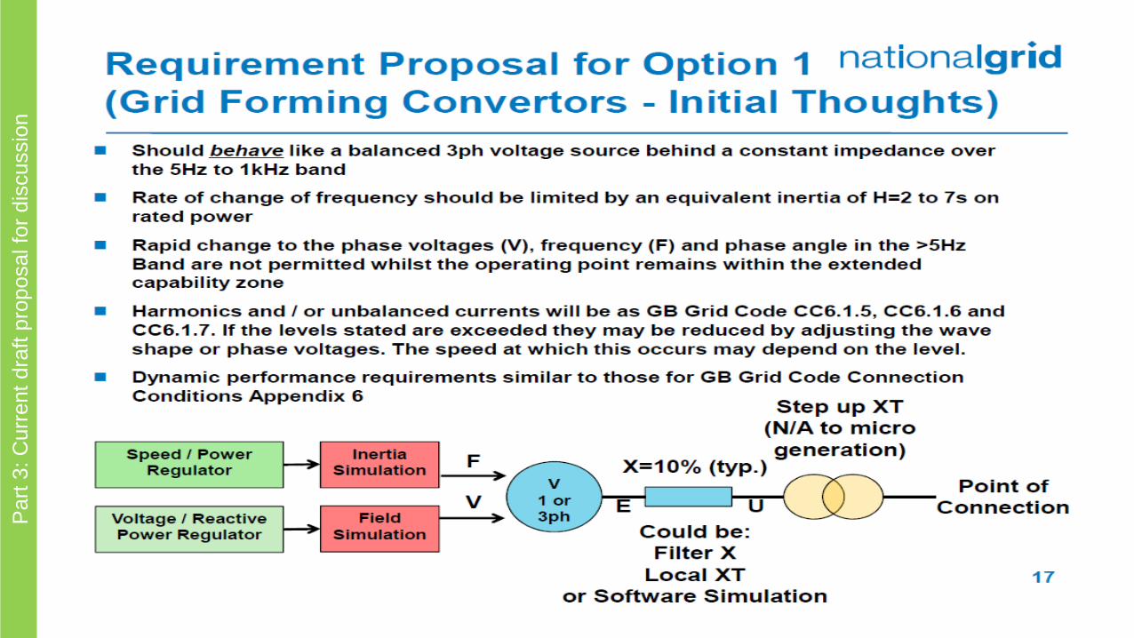
• Synthetic Inertia could be true inertia without delay or some form with an inbuilt short delay to allow for
active controls. IGD HPoPEIPS concludes that true inertia provided through Grid Forming converter
control capability seems to be a solid solution for systems with very low inherent inertia.
• Synthetic inertia with control delays can support system frequency stability when moving from a
synchronous generation based system towards a higher penetration of non-synchronous generation,
but entails a risk of other forms of system instabilities for very high penetration of this type of
generation, In addition, synthetic inertia with control delays is impractical, if active control features
responding within 20ms are needed (measurement alone need > 20ms).
Synthetic Inertia & demand response (DR) very fast active power
control (APC). Proposed parameters.
Part
1: syste
m n
eeds a
nd r
isks

59
• SPGM• Depending on the turbine size, technologies and arrangements (GT or ST gen only + generator, single, dual or tri-
shaft with GT/ST/Gen coupled, etc...), H could be ranging from circa 5 to 15s. H could be marginally modified via the
selection of larger generators in portfolio (if available). The related cost depends on many different factors; a
minimum of 5% CAPEX impact can be expected when considering the least complex solution. Economic impact will
be much higher for other units, if, for example, the generator frame is changed, affecting the overall product design.
The cost impact estimated above can be relevant also for existing units, when it is possible to implement
modifications. Arrangements for operation in synchronous condensing mode are available (clutch most common).
The costs of this modification can vary so much from a generating unit to the other that a case-by-case evaluation
shall be carried out.
• More dedicated for smaller size modules:
• The typical inertia constant is dependent from the inertia of the engine and the generator. The typical inertia
constant (H) is between 0.4 and 0.8. It is possible to add additional inertia by putting some additional mass to
the genset, for example a flywheel. The additional mass has disadvantages in other areas. For example, it
reduces the energy efficiency and leads to additional costs.
Synthetic Inertia & demand response (DR) very fast active power
control (APC). Stakeholder feedback on technical capabilities - SPGMs
Part
2: Technolo
gic
al a
nd e
conom
ic c
onstr
ain
ts
60
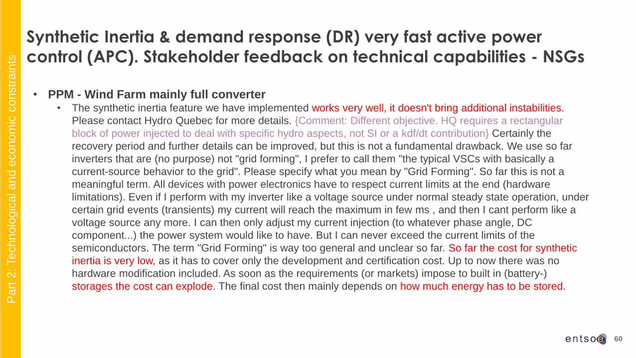
• PPM - Wind Farm mainly full converter• The synthetic inertia feature we have implemented works very well, it doesn't bring additional instabilities.
Please contact Hydro Quebec for more details. {Comment: Different objective. HQ requires a rectangular
block of power injected to deal with specific hydro aspects, not SI or a kdf/dt contribution} Certainly the
recovery period and further details can be improved, but this is not a fundamental drawback. We use so far
inverters that are (no purpose) not "grid forming", I prefer to call them "the typical VSCs with basically a
current-source behavior to the grid". Please specify what you mean by "Grid Forming". So far this is not a
meaningful term. All devices with power electronics have to respect current limits at the end (hardware
limitations). Even if I perform with my inverter like a voltage source under normal steady state operation, under
certain grid events (transients) my current will reach the maximum in few ms , and then I cant perform like a
voltage source any more. I can then only adjust my current injection (to whatever phase angle, DC
component...) the power system would like to have. But I can never exceed the current limits of the
semiconductors. The term "Grid Forming" is way too general and unclear so far. So far the cost for synthetic
inertia is very low, as it has to cover only the development and certification cost. Up to now there was no
hardware modification included. As soon as the requirements (or markets) impose to built in (battery-)
storages the cost can explode. The final cost then mainly depends on how much energy has to be stored.
Synthetic Inertia & demand response (DR) very fast active power
control (APC). Stakeholder feedback on technical capabilities - NSGs
Part
2: Technolo
gic
al a
nd e
conom
ic c
onstr
ain
ts

61
• PPM - Wind Farm mainly DFIG
• Currently synthetic inertia is not available to 50Hz wind turbines. It has been developed and already in
operation for 60Hz grids in Canada. {Comment: Again this is not considered SI, it is a solution for initial hydro
reversal}.The synthetic inertia contribution for 50Hz wind turbines in currently under investigation but it may be
expected to be similar to the 60Hz performance – maximum 10% of Pn boost for maximum of 10 seconds with
recovery period of 60 seconds after the boost and active power loss of maximum 20% of Pn. The minimum
performance values will vary across the wind turbine types mainly according to their mechanical design, rotor
diameter and aerodynamical characteristics of the blades.
• There are currently no plans to implement a grid forming control, since this seems to be a research topic with
several unanswered questions and an unclear business case. These include: • Where does the dynamic active power come from?
• Due to mechanical rating and fundamental aerodynamic limitations it will not be possible to use the wind turbine rotor
mass as a mechanical dynamic energy storage for these purposes.
• The only feasible solution seems to be some other fast storage (like batteries) that is decoupled from the “wind” part of
the generation.
• Who will pay for this storage and how large should it be?
• Is it more economic to put this dynamic storage into generation sites, in the grid or near load centers?
• How much will the dynamic component rating (especially converter rating) have to be increased?
• Who will pay for this increased rating? Will this be an ancillary service?
• If a voltage source type control (VSM) is used, how big would the choke in front of the converter have to be to provide a
useful response?
• Does this choke size lead to an increase in component voltage rating or losses?
Synthetic Inertia & demand response (DR) very fast active power
control (APC). Stakeholder feedback on technical capabilities - NSGs
Part
2: Technolo
gic
al a
nd e
conom
ic c
onstr
ain
ts

62
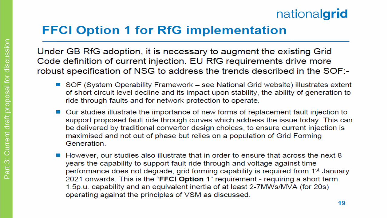
• Synchronous areas Ireland and GB are likely to face in the near future times of very high penetration and at times
extremely low inertia.
• Recommendation for a national choice of a requirement for a minimum inertia contribution H in the range 2-7
MWs/MVA as soon as possible after 2020.
• Recommendation to take into account available technical capability for new generation as well as headroom or storage.
• Inertia contribution to be assessed from a holistic perspective to avoid adverse system impacts.
• Alternatives could be considered, including dispatch constraints for connections not equipped to provide inertia.
• GB initial national proposal to cope with a range of High Penetration challenges follows in subsequent slides
• For Other synchronous areas (CE, Nordic and Baltic), • No minimum requirement for inertia contribution is considered necessary for the SA as of today
• However, if a country (as defined in HPoPEIPS) foresees extremely low inertia contribution (e.g. at times H < 1 MWs/MVA
for >10% of time) to cover cases of severe disturbances, such as becoming part of an island with inadequate
inertia, the need for the same requirements as above should be considered in collaboration with adjacent TSOs.
• DR with very fast APC
• In addition to synthetic inertia which limits RoCoF, frequency stability can be supported (to avoid too low nadir) by other
resources faster than FSM. This is the objective of DR with very fast APC as covered by NC DCC – Article 30.1.
• For this to be effective, DR with very fast APC would require the delivery of 90% of the available active power change
within 1s or 2s and be sustained for 5s or 10s to bridge a possible resource gap between inertia and FSM.
Synthetic Inertia & demand response (DR) very fast active power control (APC).
Proposed parameters – continued - The suggested outcomes are:
Part
3: C
urr
ent
dra
ft p
roposal fo
r dis
cussio
n
63
Part
3: C
urr
ent
dra
ft p
roposal fo
r dis
cussio
n

64
Part
3: C
urr
ent
dra
ft p
roposal fo
r dis
cussio
n
65
Part
3: C
urr
ent
dra
ft p
roposal fo
r dis
cussio
n
66
Part
3: C
urr
ent
dra
ft p
roposal fo
r dis
cussio
n
67
Part
3: C
urr
ent
dra
ft p
roposal fo
r dis
cussio
n

68
Initial TSO’s and stakeholders’ view on Demand Response System Frequency Control (DR SFC)

69
Demand response – System Frequency Control (DR-SFC)
DCC requirement: Article 29
1. Demand facilities and closed distribution systems may offer demand response system frequency control to relevant system
operators and relevant TSOs.
2. Demand units with demand response system frequency control shall comply with the following requirements, either individually or,
where it is not part of a transmission-connected demand facility, collectively as part of demand aggregation through a third party:a) be capable of operating across the frequency ranges specified in Article 12(1) and the extended range specified in Article 12(2);
b) be capable of operating across the voltage ranges specified in Article 13 if connected at a voltage level at or above 110 kV;
c) be capable of operating across the normal operational voltage range of the system at the connection point, specified by the relevant system
operator, if connected at a voltage level below 110 kV. This range shall take into account existing standards, and shall, prior to approval in
accordance with Article 6, be subject to consultation with the relevant stakeholders in accordance with Article 9(1);
d) be equipped with a control system that is insensitive within a dead band around the nominal system frequency of 50,00 Hz, of a width to be
specified by the relevant TSO in consultation with the TSOs in the synchronous area. For demand units connected at a voltage level below
110 kV, these specifications shall, prior to approval in accordance with Article 6, be subject to consultation with the relevant stakeholders in
accordance with Article 9(1);
e) be capable of, upon return to frequency within the dead band specified in paragraph 2(d), initiating a random time delay of up to 5 minutes before
resuming normal operation. The maximum frequency deviation from nominal value of 50,00 Hz to respond to shall be specified by the relevant
TSO in coordination with the TSOs in the synchronous area. For demand units connected at a voltage level below 110 kV, these specifications
shall, prior to approval in accordance with Article 6, be subject to consultation with the relevant stakeholders in accordance with Article 9(1). The
demand shall be increased or decreased for a system frequency above or below the dead band of nominal (50,00 Hz) respectively;
f) be equipped with a controller that measures the actual system frequency. Measurements shall be updated at least every 0,2 seconds;
g) be able to detect a change in system frequency of 0,01 Hz, in order to give overall linear proportional system response, with regard to the
demand response system frequency control's sensitivity and accuracy of the frequency measurement and the consequent modification of the
demand. The demand unit shall be capable of a rapid detection and response to changes in system frequency, to be specified by the
relevant TSO in coordination with the TSOs in the synchronous area. An offset in the steady-state measurement of frequency shall be
acceptable up to 0,05 Hz.
Part
1: syste
m n
eeds a
nd r
isks

Time delay due to
frequency
sampling
Dead band
Demand unitDemand unit controller
Voltage
transformer
actuator
(Switch:
ON/OFF)
Logical unit
(triggering)
Power system
Demand facility or Closed distribution system
Random time
delay
(up to 5 minutes)
70
Demand response – System Frequency Control (DR-SFC)
DCC requirement: Article 29
Part
1: syste
m n
eeds a
nd r
isks

71
Q1 on DR-SFC usage of wind turbines including battery storage for DR-SFC.
A: Wind turbines including battery storage are not part of NC DCC (acc. to article 3 (2)(b))):
„2. This Regulation shall not apply to:
… (b) storage devices except for pump-storage power generating modules in accordance with Article 5(2).“
Demand response – System Frequency Control (DR-SFC)
stakeholder feedback on technical capabilities
Part
2: Technolo
gic
al a
nd e
conom
ic c
onstr
ain
ts
72
Initial TSO’s and stakeholders’ view onFrequency ranges of automatic connection and gradient of active power increase
73
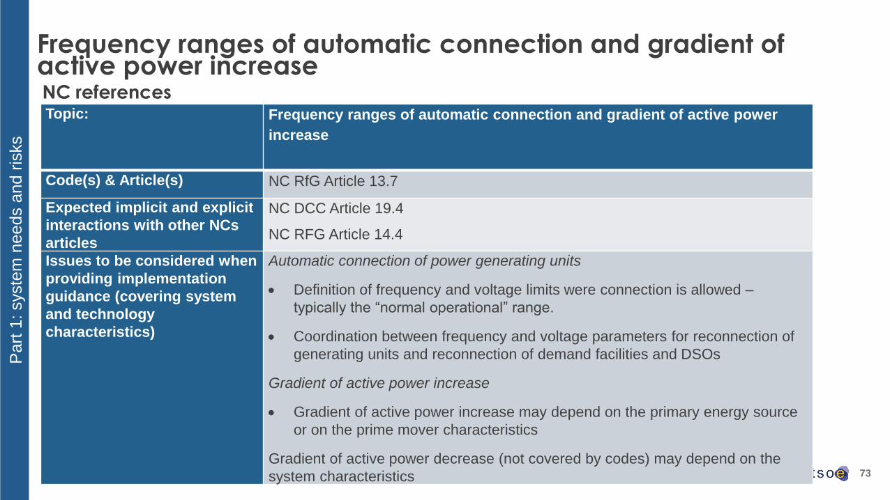
Frequency ranges of automatic connection and gradient of active power increase
Topic: Frequency ranges of automatic connection and gradient of active power
increase
Code(s) & Article(s) NC RfG Article 13.7
Expected implicit and explicit
interactions with other NCs
articles
NC DCC Article 19.4
NC RFG Article 14.4
Issues to be considered when
providing implementation
guidance (covering system
and technology
characteristics)
Automatic connection of power generating units
• Definition of frequency and voltage limits were connection is allowed –
typically the “normal operational” range.
• Coordination between frequency and voltage parameters for reconnection of
generating units and reconnection of demand facilities and DSOs
Gradient of active power increase
• Gradient of active power increase may depend on the primary energy source
or on the prime mover characteristics
Gradient of active power decrease (not covered by codes) may depend on the
system characteristics
NC references
Part
1: syste
m n
eeds a
nd r
isks
74
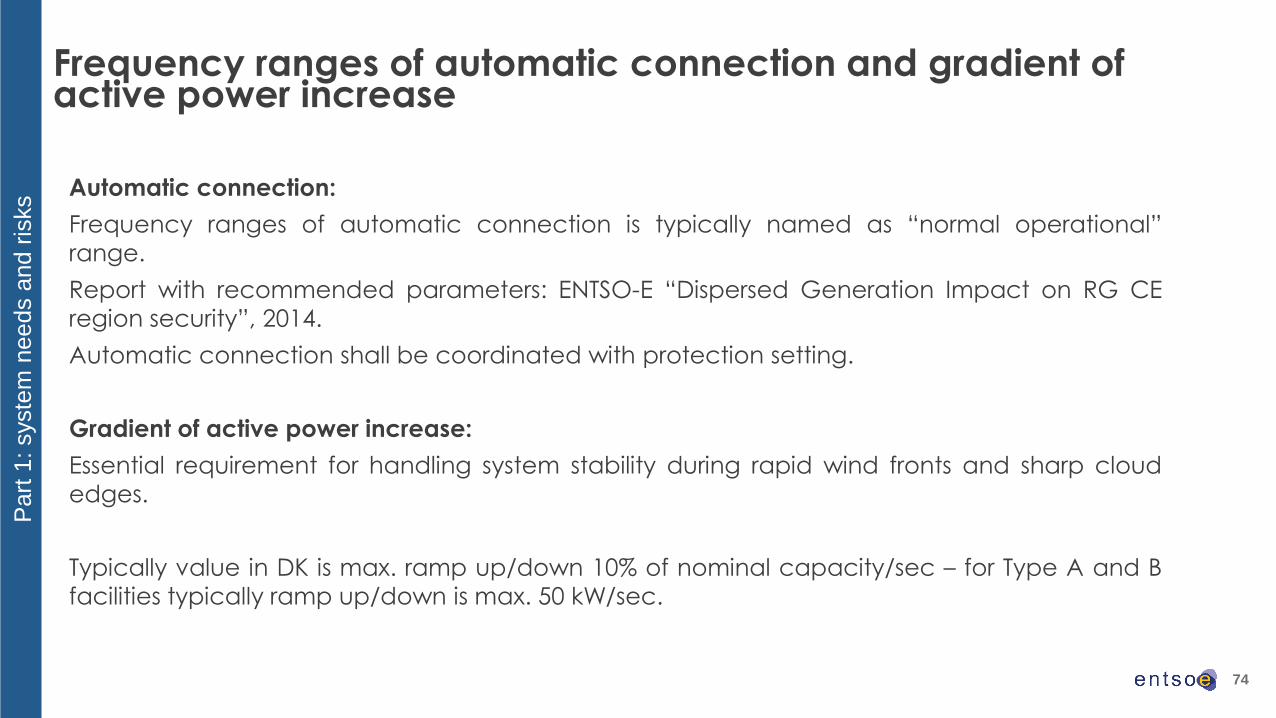
Frequency ranges of automatic connection and gradient of active power increase
Automatic connection:
Frequency ranges of automatic connection is typically named as “normal operational”
range.
Report with recommended parameters: ENTSO-E “Dispersed Generation Impact on RG CE
region security”, 2014.
Automatic connection shall be coordinated with protection setting.
Gradient of active power increase:
Essential requirement for handling system stability during rapid wind fronts and sharp cloud
edges.
Typically value in DK is max. ramp up/down 10% of nominal capacity/sec – for Type A and B
facilities typically ramp up/down is max. 50 kW/sec.
Part
1: syste
m n
eeds a
nd r
isks
75
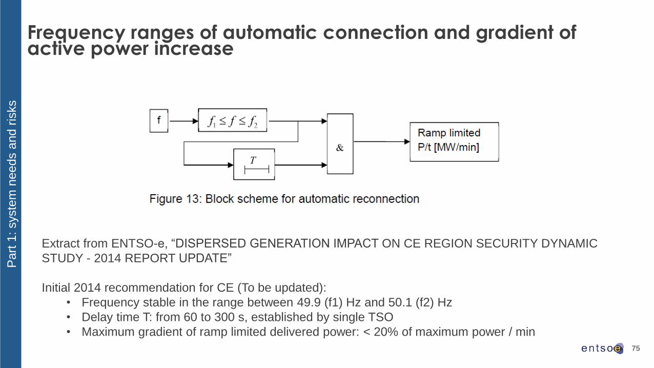
Frequency ranges of automatic connection and gradient of active power increase
Part
1: syste
m n
eeds a
nd r
isks
Extract from ENTSO-e, “DISPERSED GENERATION IMPACT ON CE REGION SECURITY DYNAMIC
STUDY - 2014 REPORT UPDATE”
Initial 2014 recommendation for CE (To be updated):
• Frequency stable in the range between 49.9 (f1) Hz and 50.1 (f2) Hz
• Delay time T: from 60 to 300 s, established by single TSO
• Maximum gradient of ramp limited delivered power: < 20% of maximum power / min

76
Frequency ranges of automatic connection and gradient of active power
increase - stakeholder feedback on technical capabilities
Part
2: Technolo
gic
al a
nd e
conom
ic c
onstr
ain
ts
No specific question raised by ENTSO-e
- Network codes on grid connection foresee coordination with “relevant system operators”. This includes
DSOs for all aspects relevant to the DSOs.

77
Initial TSO’s and stakeholders’ view onAuto reconnection after an incidental disconnection
78
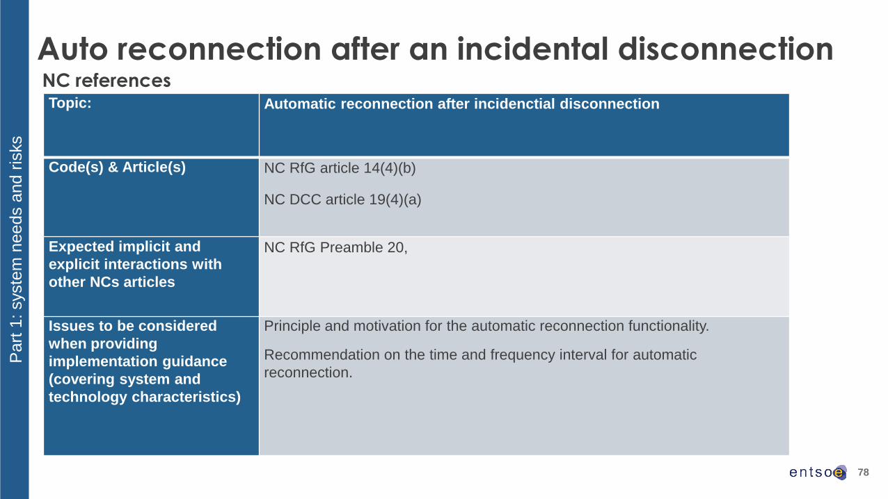
Auto reconnection after an incidental disconnection
Topic: Automatic reconnection after incidenctial disconnection
Code(s) & Article(s) NC RfG article 14(4)(b)
NC DCC article 19(4)(a)
Expected implicit and
explicit interactions with
other NCs articles
NC RfG Preamble 20,
Issues to be considered
when providing
implementation guidance
(covering system and
technology characteristics)
Principle and motivation for the automatic reconnection functionality.
Recommendation on the time and frequency interval for automatic
reconnection.
NC references
Part
1: syste
m n
eeds a
nd r
isks

79
Auto reconnection after an incidental disconnection
Automatic reconnection:
System frequency for allowing automatic reconnection shall be within the “normal
operational” range.
Ramp up rate shall be controlled after reconnection – a default value defined by operation.
Automatic reconnection shall be coordinated with protection setting.
DK parameter for auto reconnection after an incidental disconnection is a latency period of
minimum 3 min.
Part
1: syste
m n
eeds a
nd r
isks

80
No specific question raised by ENTSO-e
- Network codes on grid connection foresee coordination with “relevant system operators”. This includes
DSOs for all aspects relevant to the DSOs.
Auto reconnection after an incidental disconnection - stakeholder
feedback on technical capabilities
Part
2: Technolo
gic
al a
nd e
conom
ic c
onstr
ain
ts

81
Initial TSO’s and stakeholders’ view onAdmissible active power reduction at low frequencies
82
Admissible active power reduction at low frequencies (1/3)
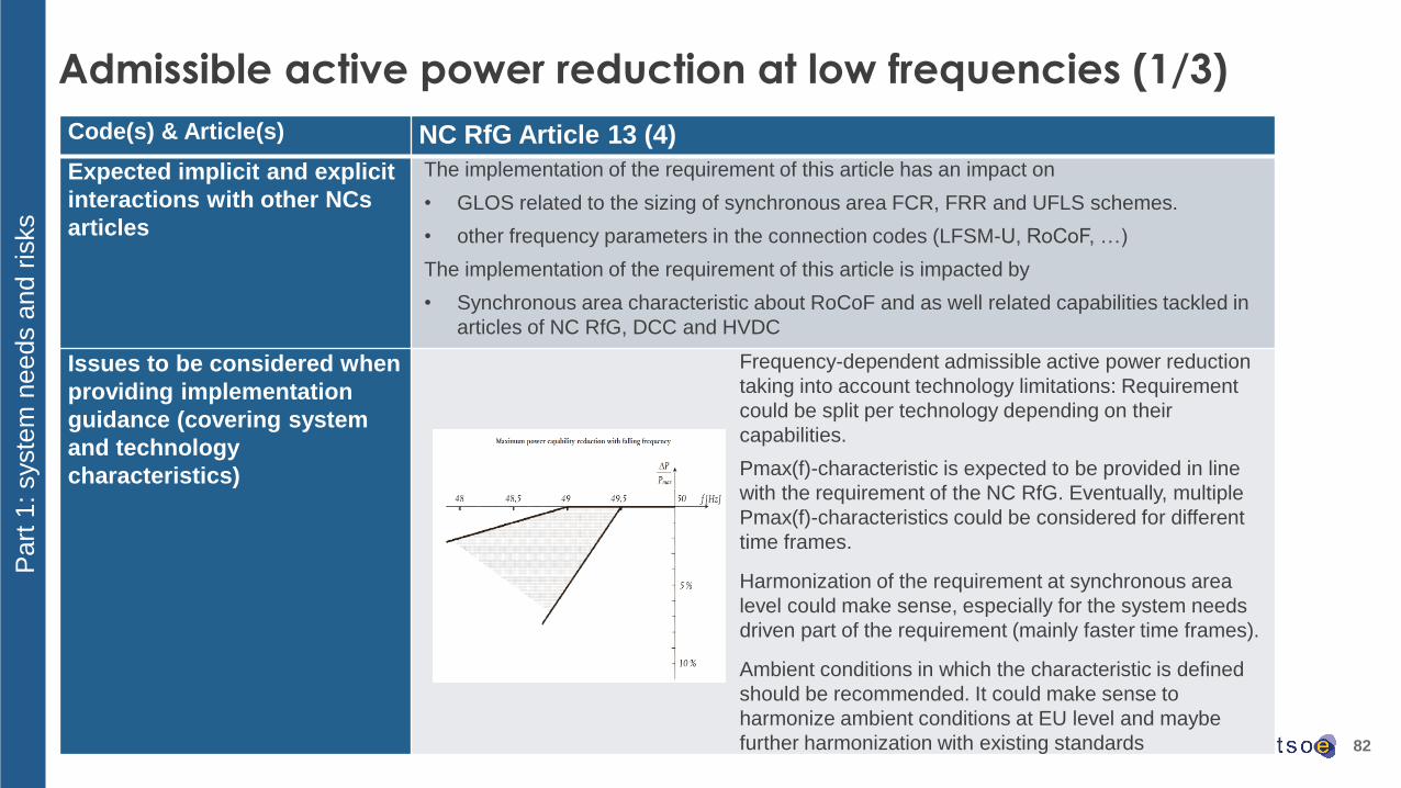
Code(s) & Article(s) NC RfG Article 13 (4)
Expected implicit and explicit
interactions with other NCs
articles
The implementation of the requirement of this article has an impact on
• GLOS related to the sizing of synchronous area FCR, FRR and UFLS schemes.
• other frequency parameters in the connection codes (LFSM-U, RoCoF, …)
The implementation of the requirement of this article is impacted by
• Synchronous area characteristic about RoCoF and as well related capabilities tackled in
articles of NC RfG, DCC and HVDC
Issues to be considered when
providing implementation
guidance (covering system
and technology
characteristics)
Frequency-dependent admissible active power reduction
taking into account technology limitations: Requirement
could be split per technology depending on their
capabilities.
Pmax(f)-characteristic is expected to be provided in line
with the requirement of the NC RfG. Eventually, multiple
Pmax(f)-characteristics could be considered for different
time frames.
Harmonization of the requirement at synchronous area
level could make sense, especially for the system needs
driven part of the requirement (mainly faster time frames).
Ambient conditions in which the characteristic is defined
should be recommended. It could make sense to
harmonize ambient conditions at EU level and maybe
further harmonization with existing standards
Part
1: syste
m n
eeds a
nd r
isks

83
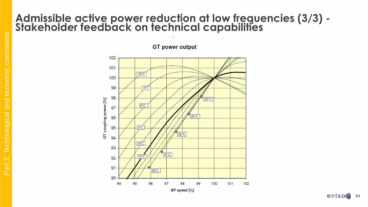
Admissible active power reduction at low frequencies (2/3) -Stakeholder feedback on technical capabilities
• PPM - Wind Farm mainly full converter• Steady state operation with rated frequency with plus or minus 7Hz is ok.
• PPM - Wind Farm mainly DFIG• Within the current NC RfG frequency ranges, wind turbines does not need to reduce active power at low frequencies.
• SPGM• Upper profile as in RfG is a major concern for gas turbines. The power reduction can be present already when the frequency
drops from the 50 Hz.
• The hotter the ambient temperature, the lower the capability to maintain power output at falling frequency. For GT, the
decrease of active power is extremely limited when at low temperature. The GT output is typically specified at ISO condition.
• Power reduction must be performed below 49 Hz in order to avoid overloading of the engine. The engines start derating with a
rate of 10 % /Hz and operate for unlimited time.
• Mainly critical for gas engine
• Maintain active power output constant at low frequencies is only possible when engines are over-sized.
• All ambient conditions (temperature, air pressure and humidity) have an impact. The reference conditions are 400 m to 500 m,
25 to 35-degrees Celsius ambient temperature and 15 to 20 g H2O/1 kg of air. The operating ambient conditions are
considered for each installation site.
Part
2: Technolo
gic
al a
nd e
conom
ic c
onstr
ain
ts
84
Admissible active power reduction at low frequencies (3/3) -Stakeholder feedback on technical capabilities
Part
2: Technolo
gic
al a
nd e
conom
ic c
onstr
ain
ts

85
Wrap-Up and Next Steps
86
2nd Public workshop on Frequency Stability Parameters for Connection Network Code
Implementation
Brussels, 20. July 2017