2wr6.. energy meters - etazgrejanje.com · energy meters 2wr6.. ultrasonic heat and cooling energy...
TRANSCRIPT

s 5378
Ultrasonic heat and cooling
energy meters 2WR6..
Ultrasonic heat and cooling energy meters to measure flow and energy in hydronic heating or cooling circuits. • Non-wearing due to non-moving parts
• Approved in accordance with EN 1434 and MID accuracy class 2
• Mounting position optional (horizontal or vertical), in return or flow
• Metering range for flow 1:100 as per EN1434 (total range 1:500)
• No inlet or outlet settling paths required
• Optical interface as per EN 62056-21
• M-bus communication
• Self-diagnostics
CE2N5378en 2014-04-04
Building Technologies

Use
The 2WR6.. heat and cooling energy meter is used to acquire energy consumption in a physically correct way. The device consists of a flow measuring section, 2 ready connected temperature sensors and a processor to calculate the energy consumption based on the flow rate and the temperature differential. The 2WR6.. is of compact design and therefore ideally suited for use in apartments. It is available for heat or cooling energy.
Temperature sensors and battery of the 2WR6.. cannot be replaced. The product is not suited for use in systems operating on water-glycol mixtures.
Functions
The heat meter consists of processor, flow measuring section and 2 temperature sensors (return temperature sensor is always integrated in the measuring tube).
- Pt500, type DS M10x1 mm, direct immersion, immersion length 27.5 mm - Pt500, type PS Ø 5.2x45 mm, direct immersion or for protection pocket
The processor is alternatively powered by … - a battery with a life of 11 years - external power supply AC/DC 24 V
The volume flow is acquired based on the ultrasonic measuring principle, free from wear due to the use of non-moving parts. The amount of energy supplied by the medium to the consumer during a certain period of time is proportional to the temperature differential of flow and return and the volume flow passing through the meter. The water volume is acquired in the measuring tube by ultrasonic pulses trans-mitted in the direction of flow and against the direction of flow. Downstream, the time required by the pulses to travel from the transmitter to the receiver is reduced, upstream it is increased. The water volume is then calculated based on these measured values. The flow and return temperatures are acquired by platinum sensors. The water volume and the difference in temperature between flow and return are multiplied and its product is integrated. The result, which is the consumed quantity of thermal or cooling energy, is recorded and displayed in the physical unit kWh/MWh or MJ/GJ, the volume in m3. A standard processor is used for all flow rate values with identical operation and an integrated service unit. The heat meter is equipped with an optical communication interface, enabling the device to be read and parameterized on site with the help of the WZR-OP-USP optical read head and the UltraAssist software. To open the meter, the calibration seal on the front of the 2WR6.. must be destroyed. The meter performs constantly self-diagnostics, allowing it to detect a number of mounting or device errors and to display them.
Restrictions
Basic design
Ultrasonic measuring principle
Processor
Optical communication interface
Manipulations
Self-diagnostics
2 / 14
Siemens Ultrasonic heat and cooling energy meters 2WR6.. CE2N5378en Building Technologies 2014-04-04
Type summary 2WR6..
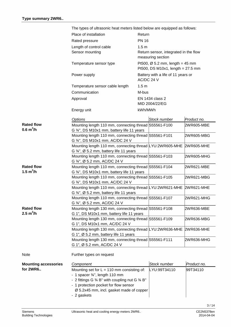
The types of ultrasonic heat meters listed below are equipped as follows: Place of installation Return Rated pressure PN 16 Length of control cable 1.5 m Sensor mounting Return sensor, integrated in the flow measuring section Temperature sensor type Pt500, Ø 5.2 mm, length = 45 mm Pt500, DS M10x1, length = 27.5 mm Power supply Battery with a life of 11 years or AC/DC 24 V Temperature sensor cable length 1.5 m Communication M-bus Approval EN 1434 class 2 MID 2004/22/EG Energy unit kWh/MWh Options Stock number Product no. Mounting length 110 mm, connecting thread G ¾", DS M10x1 mm, battery life 11 years
S55561-F100 2WR605-MBE
Mounting length 110 mm, connecting thread G ¾", DS M10x1 mm, AC/DC 24 V
S55561-F101 2WR605-MBG
Mounting length 110 mm, connecting thread G ¾", Ø 5.2 mm, battery life 11 years
LYU:2WR605-MHE 2WR605-MHE
Mounting length 110 mm, connecting thread G ¾", Ø 5.2 mm, AC/DC 24 V
S55561-F103 2WR605-MHG
Mounting length 110 mm, connecting thread G ¾", DS M10x1 mm, battery life 11 years
S55561-F104 2WR621-MBE
Mounting length 110 mm, connecting thread G ¾", DS M10x1 mm, AC/DC 24 V
S55561-F105 2WR621-MBG
Mounting length 110 mm, connecting thread G ¾", Ø 5.2 mm, battery life 11 years
LYU:2WR621-MHE 2WR621-MHE
Mounting length 110 mm, connecting thread G ¾", Ø 5.2 mm, AC/DC 24 V
S55561-F107 2WR621-MHG
Mounting length 130 mm, connecting thread G 1", DS M10x1 mm, battery life 11 years
S55561-F108 2WR636-MBE
Mounting length 130 mm, connecting thread G 1", DS M10x1 mm, AC/DC 24 V
S55561-F109 2WR636-MBG
Mounting length 130 mm, connecting thread G 1", Ø 5.2 mm, battery life 11 years
LYU:2WR636-MHE 2WR636-MHE
Mounting length 130 mm, connecting thread G 1", Ø 5.2 mm, AC/DC 24 V
S55561-F111 2WR636-MHG
Further types on request Component Stock number Product no. Mounting set for L = 110 mm consisting of: - 1 spacer ¾", length 110 mm - 2 fittings G ¾ B" with coupling nut G ¾ B" - 1 protection pocket for flow sensor Ø 5.2x45 mm, incl. gasket made of copper - 2 gaskets
LYU:99T34110 99T34110
Rated flow 0.6 m3/h
Rated flow 1.5 m3/h
Rated flow 2.5 m3/h
Note
Mounting accessories for 2WR6..
3 / 14
Siemens Ultrasonic heat and cooling energy meters 2WR6.. CE2N5378en Building Technologies 2014-04-04

Component Stock number Product no. Mounting set for L = 130 mm consisting of: - 1 spacer 1", length 130 mm - 2 fittings G 1 B" with coupling nut G 1 B" - 1 protection pocket for flow sensor Ø 5.2x45 mm, incl. gasket made of copper - 2 gaskets
LYU:99T01130 99T01130
Mounting kit, consisting of: - 2 coupling nuts G ¾" - 2 inserts R ½" - 2 gaskets
S55563-F124 WZM-E34
Mounting kit, consisting of: - 2 coupling nuts G 1" - 2 inserts R ¾" - 2 gaskets
S55563-F123 WZM-E1
Adapter from 110 mm to 130 mm, consisting of: - 1 fitting G ¾ B" to G ¾ B" - 2 gaskets
LYU:WZM-V130 WZM-V130
Adapter from 110 mm to 130 mm, consisting of: - 2 fitting G ¾ B" to G 1 B" - 2 gaskets G ¾" - 2 gaskets G 1"
LYU:WZM-V130.G1 WZM-V130.G1
Adapter from 110 mm to 165 mm, consisting of: - 2 fitting G ¾ B" to G ¾ B" - 4 gaskets
LYU:WZM-V165 WZM-V165
Adapter from 110 mm to 190 mm, consisting of: - 2 fitting G ¾ B" to G 1 B" - 2 gaskets G ¾" - 2 gaskets G 1"
LYU:WZM-V190 WZM-V190
Spacer G ¾", length 110 mm, incl. 2x gaskets
LYU:WZM-G110 WZM-G110
Spacer G 1", length 130 mm, incl. 2 gaskets
LYU:WZM-G130 WZM-G130
Spacer G 1", length 190 mm, incl. 2 gaskets
LYU:WZM-G190 WZM-G190
Sealing disk thread G ¾", for threaded connection R ½"
LYU:9060944002 9060944002
Sealing disk thread G 1", for threaded connection R ¾"
LYU:9060944003 9060944003
Welding sleeve with threaded hole for tem-perature sensor DS M10x1 mm
S55563-F121 WZT-G10
Welding sleeve G ½", 45° to pipe axis, with threaded hole G ½"
S55563-F122 WZT-G12
Welding sleeve G ½", 90° to pipe axis, with threaded hole G ½"
LYU:WZT-GLG WZT-GLG
Ball valve Rp ½" to mount sensor DS M10x1 mm, length 28 mm, max. water temperature 130 °C, PN 25
S55563-F104 WZT-K12
Ball valve Rp ¾" to mount sensor DS M10x1 mm, length 28 mm, max. water temperature 130 °C, PN 25
S55563-F120 WZT-K34
4 / 14
Siemens Ultrasonic heat and cooling energy meters 2WR6.. CE2N5378en Building Technologies 2014-04-04

Component Stock number Product no. Ball valve Rp 1" to mount sensor DS M10x1 mm, length 28 mm, max. water temperature 130 °C, PN 25
S55563-F119 WZT-K1
Ball valve R ½" with union nut G ¾" LYU:WZT-K12-34 WZT-K12-34 Ball valve R ¾" with union nut G ¾" LYU:WZT-K34-34 WZT-K34-34 Ball valve R ¾" with union nut G 1" LYU:WZT-K34-1 WZT-K34-1 Ball valve R 1" with union nut G 1" LYU:WZT-K1-1 WZT-K1-1 Adapter for ball valve to install sensor DS M10x1 mm, length 38 mm
S55563-F105 9930128002
Mounting kit for direct mounting of sensor Ø 5.2x45 mm, consisting of: - 1 sensor fitting M10x1 mm made of brass - 1 O-ring - 1 grooved pin
LYU:9930127002 9930127002
Adapter kit, consisting of: - 1 plastic adapter Ø 5.2x45 mm - 1 mounting aid for sensor Ø 5.2x45 mm - 2 O-rings
LYU:9956230 9956230
Sealing disk for temperature sensor DS M10x1 mm, Ø 8.6/5.3, size 1 mm
LYU:9060944001 9060944001
Sealing disc ½" made of copper LYU:9060948 9060948 Adapter G ½ B" with threaded hole for sensor DS M10x1 mm, incl. gasket G ½" made of copper
S55563-F116 WZT-A12
Adapter G ¾ B" with threaded hole for sensor DS M10x1 mm, incl. gasket G ¾" made of copper
LYU:WZT-A34 WZT-A34
Protection pocket G ½ B" made of brass, Ø 5.2x35 mm for sensor Ø 5.2x45 mm
S55563-F103 WZT-M35
Protection pocket G ½ B" made of brass, Ø 5.2x50 mm for sensor Ø 5.2x45 mm
LYU:WZT-M50 WZT-M50
Optical read head with USB plug for PC interface
LYU: WZR-OP-USB WZR-OP-USB
UltraAssist Standard, first license, CD with dongle for printer interface
LYU:WZX-UA-SED
WZX-UA-SED
UltraAssist Standard, second license, with dongle for printer interface
LYU:WZX-UA-SFD WZX-UA-SFD
UltraAssist Standard, first license, CD with dongle as PCMCIA card
LYU:WZX-UA-SEP WZX-UA-SEP
UltraAssist Standard, second license, with dongle as PCMCIA card
LYU:WZX-UA-SFP WZX-UA-SFP
UltraAssist Standard, first license, CD with dongle for USB interface
LYU:WZX-UA-SEU WZX-UA-SEU
UltraAssist Standard, second license, with dongle for USB interface
LYU:WZX-UA-SFU WZX-UA-SFU
The UltraAssist Light read and parameterization software is free and available on request.
Programming accessories
Read and parameterization soft-ware
5 / 14
Siemens Ultrasonic heat and cooling energy meters 2WR6.. CE2N5378en Building Technologies 2014-04-04

Ordering
When ordering, please give quantity, description, product no. and stock number.
The 2WR6.. is supplied complete with Mounting Instructions in different languages, 2 gaskets and a seal.
The Mounting Instructions are supplied in 18 languages: Bulgarian, Chinese, Croatian, Czech, Dutch, English, French, German, Greek, Hungarian, Italian, Norwegian, Polish, Russian, Slovakian, Slovenian, Spanish and Turkish.
Technical design
Order numbers Product no. Stock number Description 2WR605-MBE S55561-F100 Ultrasonic heat meter
Scope of delivery
Languages
Preasure drop characteristic
6 / 14
Siemens Ultrasonic heat and cooling energy meters 2WR6.. CE2N5378en Building Technologies 2014-04-04

Display
The 2WR6.. has an easy-to-read 7-digit LCD to show different readings (e.g. energy or volume). The meter’s display is arranged in the form of 2 loops:
- User loop
- Service loop
When making a short press (<2 seconds), the user loop appears, showing line by line. After the last line, the first line reappears. When making a long press (>10 seconds), the service loop returns to the first line. Short presses then show the loop’s individual lines. The service loop can be quit by pressing the button (3 seconds), or automatically after 30 minutes.
User loop LOOP 0
1234567 kWh Cumulated quantity of energy 12345.67 m3 Cumulated volume 888888 kWh Segment test F------- Error message with error number
Service loop LOOP 1
0.739 m3/h Current flow rate 19.7 kW Current output 80 47 °C Current flow and return temperature 01.08.12 D Date 1234 Bh Number of operating hours 17 Fh Missing hours 1234567 Device number (7 digits) PuISE CH Remote reading mode (optional) 123 A Primary address with optional M-bus 1234567 K Customer number (7 digits) 15.08.12 F0 Data stamp for F0 prewarning 3-01 FW Firmware version 31.12.11 V Storage day previous year (due date) 1234567 kWh Energy previous year on due date 1234567 m3 Volume previous year on due date
Operating button
Optical interface
Calibration seal
Display
7 / 14
Siemens Ultrasonic heat and cooling energy meters 2WR6.. CE2N5378en Building Technologies 2014-04-04

For a period of 15 months on the monthly due date, the meter stores the values of …
- energy (meter reading), - volume (meter reading), and - missing hours (metering hours).
When the meter displays the monthly due date, the respective monthly values can be made to appear when pressing the button for 3 seconds. The monthly values can also be read via the optical interface. Error code Error Remedy (service personnel)
FL nEG Wrong direction of flow Check flow or installation direction; correct if necessary
Possibly alternating with: DIFF nEG Negative temperature differential Check place of installation of
sensors; correct if necessary Possibly alternating with: F0 No metering of flow Air in the measuring section/
pipe, vent pipe (delivery condition)
F1 Interruption in the flow sensor Meter exchange by specialist F2 Interruption in the return sensor Meter exchange by specialist F3 Electronics for temperature
evaluation defective Meter exchange by specialist
F4 Battery exhausted Meter exchange by specialist F5 Short-circuit in the flow sensor Meter exchange by specialist F6 Short-circuit in the return sensor Meter exchange by specialist F7 Memory internally
malfunctioning Meter exchange by specialist
F8 Error F1, F2, F3, F5 or F6 pend-ing for more than 8 hours, detection of tampering attempts. No further metering.
Measure to be taken depend on error code. Error message F8 must be reset by service personnel
F9 Error in electronics Meter exchange by specialist The processor stores the meter readings of energy, volume and missing time with their date stamps on a yearly due day. The due day for previous year values can be parameterized. The processor stores the meter readings of energy, volume and missing time with their date stamps for up to 15 months on the due day of each month. The 2WR6.. comes programmed as follows: • Due day [TT.MM]: 01.01
123 Fh Missing hours previous year --.--.-- C Code input for parameterization 31.07.12 Storage day month 1…15 Press button >3 s 1234567 kWh Energy previous month on due date 1234567 m3 Volume previous month on due date 8 Fh Missing hours previous month on due date
Error messages
Previous year values
Monthly values
Standard parameters
8 / 14
Siemens Ultrasonic heat and cooling energy meters 2WR6.. CE2N5378en Building Technologies 2014-04-04

Mounting
The meter’s mounting position is optional, the place of installation (return or flow) must correspond to the type of meter used. The flow measuring section must always be installed in the return. Inlet or outlet settling paths are not required. If the meter is installed in the common return of 2 heating circuits (e.g. space heating and DHW), the place of installation must have an adequate distance from the T-piece (min. 10 x DN) to allow the different water temperatures to properly mix. Before installing the meter, the system must be thoroughly flushed. Install the flow measuring section between 2 shutoff valves with the arrow pointing in the direction of flow. The sensors must be installed in the same water circuit as the flow measuring section (observe mixing). The sensors can be fitted in T-pieces, ball valves, direct immersed or in pockets (national regulations must be observed). In any case, the end of the sensors must extend to at least the pipe center. Temperature sensors and fittings must be sealed to prevent tampering. T-piece
Example of integration with T-piece and meter with 110 mm fitting Ball valve
Example of integration with ball valve and meter with 190 mm fitting When used as a cooling energy meter, it must be made certain that the black cover on the measuring tube points to the side or downward to avoid problems resulting from condensation. In that case, the processor must be detached from the flow measuring section to be mounted on the wall, for instance.
Flow measuring section
Note
9 / 14
Siemens Ultrasonic heat and cooling energy meters 2WR6.. CE2N5378en Building Technologies 2014-04-04

Transducer cover Permissible mounting position when metering cooling energy The ambient temperature at the processor must not exeed 55 °C. Direct sunlight must be avoided. For water temperatures between 10 °C and 90 °C, the processor can be left on the flow measuring section or can be secured to the wall (detached mounting). To reposition the processor, remove it from the flow measuring section, turn it by 90° or 180° and replace it on the adapter plate until it snaps into place. For water temperatures above 90 °C or below 10 °C, the processor must be secured to the wall (split mounting). To mount the processor on the wall, remove it from the flow measuring section including the adapter plate. The latter must then be secured to the wall so that the processor can be replaced on the adapter plate until it snaps into place.
Securing plate for wall mounting Wall mounting
Maintenance notes
The meters are maintenance-free. National calibration regulations must be observed. The devices are considered electronics devices for disposal in terms of European Directive 2012/19/EU and may not be disposed of as domestic waste. • Dispose of the device via the channels provided for this purpose. • Comply with all local and currently applicable laws and regulations. • Dispose of empty batteries at designated collection points.
Warranty service
The application-related technical data are only guaranteed together with the products mentioned in this Data Sheet. If the meters are used in connection with third-party devices that are not explicitly mentioned, the user must ensure proper functioning. In that case, Siemens will not provide any service or warranty.
Processor
Maintenance
Disposal
10 / 14
Siemens Ultrasonic heat and cooling energy meters 2WR6.. CE2N5378en Building Technologies 2014-04-04

Technical data
Battery - Battery type - Battery voltage - Battery service life
Lithium battery (cannot be replaced) 3.6 V 11 years
Via external SELV - Voltage range - Frequency - Maximum power consumption - Length of connecting cable - Galvanic separation
AC 12…36 V or DC 12…42 V 50 / 60 Hz or DC 0,8 VA 1.5 m Existing
Measuring range (national approvals may differ)
2…180 °C
Range of temperature differential ΔΘ 3…80 K
Temperature response threshold 0.2 K
Thermal coefficient Shifting-compensated
Temperature measuring error without sensor (0.5 + ΔΘmin./ΔΘ) %, max. 1.5% at ΔΘ = 3 K
Sensing element Pt500 as per EN 60751
Type Ø 5.2x45 mm
DS M10x1 mm as per EN 1434
Temperature range (national approvals may differ)
5…105 °C
Max. temperature tmax. - Heat - Cooling energy
105 °C 50 °C
Rated pressure 1.6 MPa (PN 16)
Rated flow qp m3/h 0.6 1.5 2.5 Metrological class 1:100* 1:100* 1:100*
Max. flow qs m3/h 1.2 3 5
Min. flow qi l/h 6** 15** 25**
Response threshold l/h 2.4 6.0 10
Pressure drop at qp Mounting length 110 mm Δp mbar Mounting length 130 mm Δp mbar Mounting length 190 mm Δp mbar
150 ---
150
150 160 160
---
200 200
Flow rate at Δp = 1 bar, kv
110 mm m3/h 130 mm m3/h 190 mm m3/h
1.5 --- 1.5
3.9 3.8 3.8
--- 5.6 5.6
Mounting position Optional
* In Germany: 1:50 ** In Germany: Twice as high
Processor
Power supply alternatively - Battery
- AC/DC 24 V
Function data
Temperature sensors
Flow measuring section Function data
11 / 14
Siemens Ultrasonic heat and cooling energy meters 2WR6.. CE2N5378en Building Technologies 2014-04-04
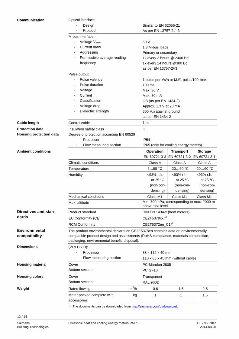
Optical interface - Design - Protocol
Similar to EN 62056-21 As per EN 13757-2 / -3
M-bus interface - Voltage Vmax. - Current draw - Addressing - Permissible average reading
frequency
50 V 1.3 M-bus loads Primary or secondary 1x every 3 hours @ 2400 Bd 1x every 24 hours @300 Bd as per EN 13757-2/-3
Pulse output - Pulse valency - Pulse duration - Voltage - Current - Classification - Voltage drop - Dielectric strength
1 pulse per kWh or MJ/1 pulse/100 liters 100 ms Max. 30 V Max. 30 mA OB (as per EN 1434-2) Approx. 1.3 V at 20 mA 500 Veff against ground as per EN 1434-2
Control cable 1 m
Insulation safety class Degree of protection according EN 60529
- Processor - Flow measuring section
III IP54 IP65 (only for cooling energy meters)
Operation EN 60721-3-3
Transport EN 60721-3-2
Storage EN 60721-3-1
Climatic conditions Class A Class A Class A Temperature 5…55 °C -20…60 °C -20…60 °C
Humidity <93% r.h. at 25 °C
(non-con-densing)
<93% r.h. at 25 °C
(non-con-densing)
<93% r.h. at 25 °C
(non-con-densing)
Mechanical conditions Class M1 Class M1 Class M1 Max. altitude Min. 700 hPa, corresponding to max. 2000 m
above sea level
Product standard DIN EN 1434-x (heat meters)
EU Conformity (CE) CE2T5378xx *)
RCM Conformity CE2T5372en_C1*)
The product environmental declaration CE2E5378en contains data on environmentally compatible product design and assessments (RoHS compliance, materials composition, packaging, environmental benefit, disposal).
(W x H x D): - Processor - Flow measuring section
88 x 112 x 40 mm 110 x 85 x 45 mm (without cable)
Cover Bottom section
PC-Marolon 2805 PC GF10
Cover Bottom section
Transparent RAL 9002
Rated flow qp m3/h 0.6 1.5 2.5
Meter packed complete with kg accessories
1 1 1,5
*) The documents can be downloaded from http://siemens.com/bt/download.
Communication
Cable length
Protection data Housing protection data
Ambient conditions
Directives and stan-dards
Environmental compatibility
Dimensions
Housing material
Housing colors
Weight
12 / 14
Siemens Ultrasonic heat and cooling energy meters 2WR6.. CE2N5378en Building Technologies 2014-04-04
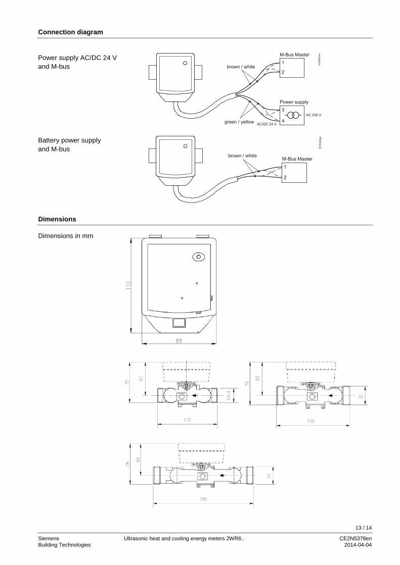
Connection diagram
Dimensions
Power supply AC/DC 24 V and M-bus
Battery power supply and M-bus
Dimensions in mm
13 / 14
Siemens Ultrasonic heat and cooling energy meters 2WR6.. CE2N5378en Building Technologies 2014-04-04

Temperature sensor 45 mm for protection pocket Temperature sensor 27.5 mm for direct fitting
Protection pocket Adapter
Mounting sensor adapter set
2012 - 2014 Siemens Switzerland Ltd. Subject to change 14 / 14
Siemens Ultrasonic heat and cooling energy meters 2WR6.. CE2N5378en Building Technologies 2014-04-04