3-12 network quality check tool via hpfp protocol a on
TRANSCRIPT

1 Introduction
In the coming ultra-high-speed satellite communica-tion era, high-speed data transmission via geostationary orbit satellites is one of the most promising technologies. In 1992, the National Institute of Information and Communication Technology (NICT) collaborated with the Japan Aerospace Exploration Agency (JAXA) to develop a gigabit satellite, called Wideband InterNetworking engi-neering test and Demonstration Satellite (WINDS). One of the goals of high-speed satellite communication technology in the Ka band of WINDS after its launch in February 2008 is to realize high-speed data transmission over Internet protocol (IP) at high throughput (up to the Gbps level).
There are two kinds of transponders onboard WINDS, which are different communication modes in service. In the bent-pipe mode used for the past satellites, frequency of uplinked codes transmitted from earth stations are converted and amplified to be downlinked to earth stations. In the regenerative mode, uplinked codes transmitted from earth stations are demodulated. The codes are regenerative
baseband switched, and then the modulated codes are downlinked to earth stations. NICT has conducted satellite communication experiments with point-to-point connec-tion based on the bent-pipe mode using direct modulation and demodulation apparatus (modem) developed on its own. In 2014, throughput of 3.2 Gbps (effectively 2.75 Gbps) was realized in the datagram type video streaming experi-ment using User Datagram Protocol (UDP) in the WINDS network [1]. In addition, in 2016, the throughput of 2.6 Gbps was achieved in the experiment of data stream type data transmission using High-performance and Flexible Protocol (HpFP) developed by NICT [2].
In the near future, networks with both robustness and reliability will be very useful in emergencies such as disas-ters. For example, ultra-high-speed satellite communication using geostationary orbit satellites will be used to comple-ment terrestrial high-speed communication networks. For this purpose, the quality of satellite communication links is important. The code error rate or bit error rate (BER) is the percentage of bits that have errors relative to the total number of bits received in a transmission, and is used as
3-12 A Network Quality Check Tool via HpFP Protocol on WINDS Satellite Link
Ken T. MURATA, Kazunori YAMAMOTO, Praphan PAVARANGKOON, Kenji SUZUKI, Toshio ASAI, Tomoshige KAN, Kazuya MURANAGA, Takamichi MIZUHARA,
Yuya KAGEBAYASHI, Yasunori KAKIZAWA, and Masatomo YAHATA
Nowadays, the concept of high throughput satellites (HTS) is developed to provide high data rates to users. The modern HTS is widely used in high-speed network communications, especially on geostationary orbits and deep space networks. It is well known that a network throughput of transmission control protocol (TCP), which is one of the most popular protocols, is limited due to latency and inevitable packet loss on the network link between the Earth and the satellite. Ku-band and Ka-band operations for the HTS tend to suffer from more packet losses than the lower frequency band operations, such as X-band and S-band operations. In this paper, we develop a new protocol on the HTS network, named the High-performance and Flexible Protocol (HpFP). A network quality measurement tool, called hperf, is introduced to prove that the HpFP is able to achieve 1.6 Gbps with single connection, theoretically maximum throughput, on the WINDS satellite link with bent-pipe mode. The Cyclic Redundancy Check (CRC) function is additionally implemented on the hperf. The experiment results show that the HpFP enables data transfer up to 100 Mbps associated with simultaneous CRC of all packets over the WINDS network. In addition, the correlation between packet loss on the HpFP and bit error detected by the CRC is provided to show a weak dependence on each other.
Title:J2017W-03-12.indd p167 2018/01/31/ 水 11:31:41
167
3 Ultra-High-Speed Satellite Communication Technology
an index of quality of telemetry. However, the BER does not show directly the IP packet arrival rate, which is neces-sary information for practical communication protocols. In general geostationary orbit satellite communication service including WINDS, there is no method for network applica-tions to obtain a parameter in real time, which shows the quality of satellite communication links such as BER. Therefore, a tool to measure the transmission condition of satellite links is needed. To the best of our knowledge, however, no tools for measuring network conditions have addressed a geostationary orbit satellite link at more than 1 Gbps.
In this paper, we propose a novel tool to measure the packet loss ratio (PLR) of satellite communication links and cyclic redundancy check (CRC) errors, named hperf. hperf is based on the HpFP socket library [3]. We evaluate the performance of hperf in the WINDS network.
The remainder of this paper is organized as follows. Section 2 presents the results of data communication ex-periments for the bent-pipe mode of WINDS conducted in the past. In Section 3, we explain about hperf and imple-mentation of the CRC error detection. Section 4 presents the results of measurement of network conditions over WINDS. Finally, we outline future works and conclude the paper in Section 5.
2 WINDS with bent-pipe mode for data transmission
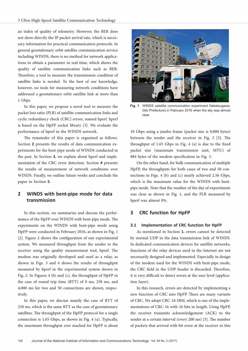
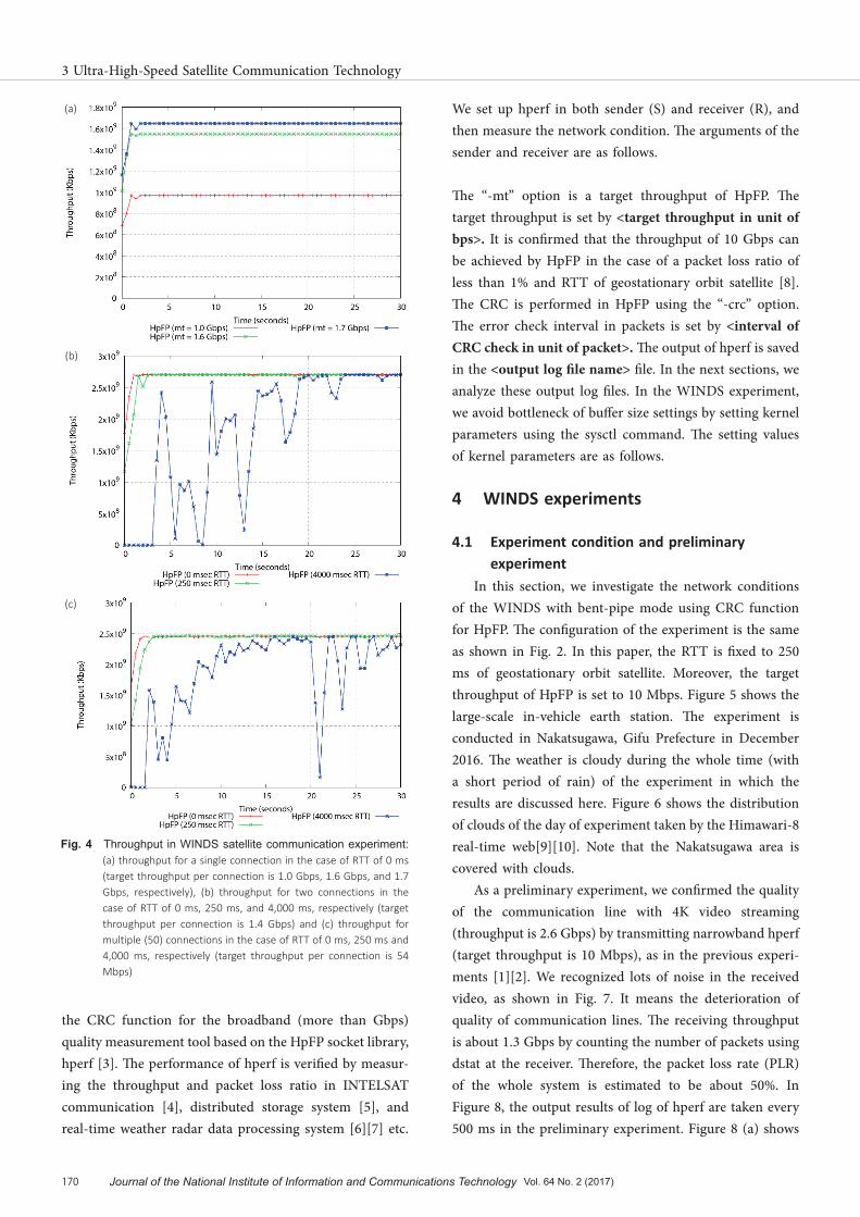
In this section, we summarize and discuss the perfor-mance of the HpFP over WINDS with bent-pipe mode. The experiments on the WINDS with bent-pipe mode using HpFP were conducted in February 2016, as shown in Fig. 1 [2]. Figure 2 shows the configuration of our experimental system. We measured throughput from the sender to the receiver using the quality measurement tool, hperf. The modem was originally developed and used as a relay, as shown in Figs. 3 and 4 shows the results of throughput measured by hperf in the experimental system shown in Fig. 2. In Figures 4 (b) and (c), the throughput of HpFP in the case of round trip time (RTT) of 0 ms, 250 ms, and 4,000 ms for two and 50 connections are shown, respec-tively.
In this paper, we discuss mainly the case of RTT of 250 ms, which is the same RTT as the case of geostationary satellites. The throughput of the HpFP protocol for a single connection is 1.65 Gbps, as shown in Fig. 4 (a). Typically, the maximum throughput ever reached for HpFP is about
10 Gbps using a jumbo frame (packet size is 9,000 bytes) between the sender and the receiver in Fig. 2 [3]. The throughput of 1.65 Gbps in Fig. 4 (a) is due to the fixed packet size (maximum transmission unit, MTU) of 884 bytes of the modem specification in Fig. 3.
On the other hand, for bulk communication of multiple HpFP, the throughputs for both cases of two and 50 con-nections in Figs. 4 (b) and (c) nearly achieved 2.56 Gbps, which is the maximum value for the WINDS with bent-pipe mode. Note that the weather of the day of experiments was clear as shown in Fig. 1, and the PLR measured by hperf was almost 0%.
3 CRC function for HpFP
3.1 Implementation of CRC function for HpFPAs mentioned in Section 1, errors cannot be detected
by normal UDP in the data transmission link of WINDS. In dedicated communication devices for satellite networks, functions of the relay devices used in the Internet are not necessarily designed and implemented. Especially in design of the modem used for the WINDS with bent-pipe mode, the CRC field in the UDP header is discarded. Therefore, it is very difficult to detect errors at the user level (applica-tion layer).
In this research, errors are detected by implementing a new function of CRC into HpFP. There are many variants of CRC. We adopt CRC-16-IBM, which is one of the imple-mentations of CRC-16 with 16 bits in length. Using HpFP, the receiver transmits acknowledgement (ACK) to the sender at a certain interval (every 200 ms) [3]. The number of packets that arrived with bit error at the receiver in this
Fig.F 1 WINDS satellite communication experiment Nakatsugawa, Gifu Prefecture) in February 2016 when the sky was almost clear
Title:J2017W-03-12.indd p168 2018/01/31/ 水 11:31:41
3 Ultra-High-Speed Satellite Communication Technology
168 Journal of the National Institute of Information and Communications Technology Vol. 64 No. 2 (2017)

interval is reported to the sender. The error rate during time step i is given by M[i]/N[i] × 100 (%), where the number of packets arrived during this interval is N[i], and the number of packets containing error is M[i]. Using the CRC function for HpFP, a packet containing multiple bit errors is counted as one.
3.2 Interface of CRC function for HpFPThe objective of this research is to monitor the network
condition of the WINDS with bent-pipe mode using hperf. We analyze the network condition and the failure by monitoring network parameters. Since there is no quantita-
tive method to verify the quality of the network at the application layer and transport layer, we measured the network condition using a 4K video transmission system for the WINDS with bent-pipe mode [1] [2]. We transferred a 4K video from the sender equipped with a 4K camera and confirmed the quality of the movie on a monitor of the receiver by visual inspection. Although the verification of quality aspects cannot be conducted by this method, the confirmation of visual qualitative quality is possible. Therefore, this method is helpful as a reference of the qual-ity of measurements.
As mentioned above, in this research, we implement
Fig.F 2 Experiment model of WINDS satellite communicationSchematic diagram of WINDS data transmission test system and utilization system
Sender Receiver
WINDS Satellite
10GbE NIC
10GbE NICTX Modem
10GbE NICRX Modem
10GbE NIC
Schematic diagram of WINDS data transmission test system and utilization system
Transmissionpath
Throughput: 3.2 Gbps(Efficiently: 2.76 Gbps)
Latency: 250ms x2
1GbE NIC 1GbE NICReturn path
Return path (latency: 0 ‐ 4000 msec)tc command tc command
Fig.F 3 Schematic diagram of modem for WINDS with bent-pipe mode Direct modulation/demodulation (modem) for reconfigurable communication device
Direct modulation/demodulation (modem) for reconfigurable communication device
4K-U
HD
Dis
play
Hig
h-En
d PC
10G
bE I/
F Bo
ard
4K-U
HD
Dis
play
Hig
h-En
d PC
10G
bE I/
F Bo
ard
DEM PWBDirect OFDM MODEM
MOD PWB
LNC
BUCTWTA
WINDS
18.25GHz28.05GHz
1.93GHz
2.45GHz
IF IN
IF OUT
HSM
C IFBB
FPGADEMFPGA
HSM
C IFBB
FPGAMODFPGA
TX Modem
RX Modem
Title:J2017W-03-12.indd p169 2018/01/31/ 水 11:31:41
169
3-12 A Network Quality Check Tool via HpFP Protocol on WINDS Satellite Link
the CRC function for the broadband (more than Gbps) quality measurement tool based on the HpFP socket library, hperf [3]. The performance of hperf is verified by measur-ing the throughput and packet loss ratio in INTELSAT communication [4], distributed storage system [5], and real-time weather radar data processing system [6][7] etc.
We set up hperf in both sender (S) and receiver (R), and then measure the network condition. The arguments of the sender and receiver are as follows.
The “-mt” option is a target throughput of HpFP. The target throughput is set by <target throughput in unit of bps>. It is confirmed that the throughput of 10 Gbps can be achieved by HpFP in the case of a packet loss ratio of less than 1% and RTT of geostationary orbit satellite [8]. The CRC is performed in HpFP using the “-crc” option. The error check interval in packets is set by <interval of CRC check in unit of packet>. The output of hperf is saved in the <output log file name> file. In the next sections, we analyze these output log files. In the WINDS experiment, we avoid bottleneck of buffer size settings by setting kernel parameters using the sysctl command. The setting values of kernel parameters are as follows.
4 WINDS experiments
4.1 Experiment condition and preliminary experiment
In this section, we investigate the network conditions of the WINDS with bent-pipe mode using CRC function for HpFP. The configuration of the experiment is the same as shown in Fig. 2. In this paper, the RTT is fixed to 250 ms of geostationary orbit satellite. Moreover, the target throughput of HpFP is set to 10 Mbps. Figure 5 shows the large-scale in-vehicle earth station. The experiment is conducted in Nakatsugawa, Gifu Prefecture in December 2016. The weather is cloudy during the whole time (with a short period of rain) of the experiment in which the results are discussed here. Figure 6 shows the distribution of clouds of the day of experiment taken by the Himawari-8 real-time web[9][10]. Note that the Nakatsugawa area is covered with clouds.
As a preliminary experiment, we confirmed the quality of the communication line with 4K video streaming (throughput is 2.6 Gbps) by transmitting narrowband hperf (target throughput is 10 Mbps), as in the previous experi-ments [1][2]. We recognized lots of noise in the received video, as shown in Fig. 7. It means the deterioration of quality of communication lines. The receiving throughput is about 1.3 Gbps by counting the number of packets using dstat at the receiver. Therefore, the packet loss rate (PLR) of the whole system is estimated to be about 50%. In Figure 8, the output results of log of hperf are taken every 500 ms in the preliminary experiment. Figure 8 (a) shows
(a)
(b)
(c)
Fig.F 4 Throughput in WINDS satellite communication experiment:(a) throughput for a single connection in the case of RTT of 0 ms (target throughput per connection is 1.0 Gbps, 1.6 Gbps, and 1.7 Gbps, respectively), (b) throughput for two connections in the case of RTT of 0 ms, 250 ms, and 4,000 ms, respectively (target throughput per connection is 1.4 Gbps) and (c) throughput for multiple (50) connections in the case of RTT of 0 ms, 250 ms and 4,000 ms, respectively (target throughput per connection is 54 Mbps)
Title:J2017W-03-12.indd p170 2018/01/31/ 水 11:31:41
3 Ultra-High-Speed Satellite Communication Technology
170 Journal of the National Institute of Information and Communications Technology Vol. 64 No. 2 (2017)

the time variation of throughput of hperf and “Actual Throughput” shows the effective throughput measured by the receiver (other throughputs are not discussed in this study). Figure 8 (b) shows the time variation of the PLR and RTT. The measured throughput is much less than 10 Mbps as shown in Fig. 8 (a), and the PLR is over 60% at maximum as shown in Fig. 8 (b). There is a large discrep-ancy between this result and that in Fig. 4. This may be caused by network disturbance. In Subsection 4.2, we in-vestigate the cause of this result by checking the bit error using the “-crc” option.
4.2 Results of experiments4.2.1 Case of no occurrence of network disturbance
The time line of the experiment is shown in Fig. 9. The time of no occurrence of network disturbance is marked
with green (as discussed in Subsubsection 4.2.1 and Subsection 4.4) and the time of network disturbance is marked with blue (as discussed in Subsubsection 4.2.2) to distinguish the condition over time. Note that the network condition during the experiment is not stable and the network disturbance happened multiple times.
Figure 10 shows the result of measurement for the time of no occurrence of network disturbance. The formats of Figs. 10 (a) and (b) are the same as those of Figs. 8 (a) and (b). The data shown in Fig. 10 is taken 20 minutes after the measurement of data shown in Fig. 8. The weather of this period is cloudy and the cloud distribution is almost the same, as shown in Fig. 6.
Fig.F 5 WINDS satellite communication experiment (Nakatsugawa, Gifu Prefecture) in December 2016 when the weather is almost always cloudy or rainy
Fig.F 7 4K video streaming experiment by WINDS (the noise is recognizable on the monitor)
Fig.F 6 Distribution of cloud on the day of experiment taken by Himawari-8 real-time web (December 27, 2016)
中津川(Nakatsugawa)
Fig.F 8 Results of preliminary experiment: (a) throughput and (b) PLR and RTT
(a)
(b)
Title:J2017W-03-12.indd p171 2018/01/31/ 水 11:31:41
171
3-12 A Network Quality Check Tool via HpFP Protocol on WINDS Satellite Link

The effective throughput shown in Fig. 10 (a) is differ-ent from that shown in Fig. 8 (a). The throughput of HpFP is slightly lower than the target throughput of 10 Mbps, which is a preferable result. Although some packet loss occurs as shown in Fig. 10 (b), it does not happen con-tinuously. In addition, the RTT is almost stable, except the beginning and the end of the experiment. The decrease in throughput in Fig. 10 (a) often occurs with the occurrence of packet loss in Fig. 10 (b).
Figure 10 (c) shows the time variation of the number of error detection by CRC. The detection is done every 200 ms. A few errors are detected at the beginning, but the number of error detection is almost zero afterwards. It means that the error detection by CRC is quite small as shown in Fig. 10 (c). Most of the packet loss in Fig. 10 (b) are not caused by the bit error.4.2.2 Case of occurrence of network disturbance
The results of measurement during the network distur-bance shown in Fig. 9 are shown in Figs. 11 and 12. The measurement shown in Fig.11 is conducted eight minutes before the measurement shown in Fig. 10 (that is 12 min-utes after that shown in Fig. 8). The measurement shown in Fig. 12 is conducted three minutes after the measure-
ment shown in Fig. 10. The formats of both the figures are the same as that of Fig. 10. This experiment is conducted before and after the measurement shown in Fig. 10. It means that the quality of WINDS communication lines varied during a short time.
The effective throughputs shown in Figs. 11 (a) and 12 (a) are significantly smaller than the target throughput of 10 Mbps for HpFP, which is the same as the case of Fig. 8 (a). This is because the effect of the packet loss shown in Figs. 11 (b) and 12 (b) is large. It is known that HpFP achieves high transmission performance at a certain PLR [3]. However, if the PLR is larger than 10% in geosta-tionary orbit satellite communication in which the RTT is 500 ms, the throughput decreases [8]. Moreover, in Figs. 11 (b) and 12 (b), RTT is stable at around 500 ms. This implies that the cause of the decrease in throughput in Figs. 11 (a) and 12 (b) is not overflow of the buffer in the modem or in the transponder.
Figures 11 (c) and 12 (c) show the time variation in the number of error. The time interval of data acquisition is the same as that in Fig.10 (c) of 200 ms. The error detection
Fig.F 10 Experiment of no occurrence of network disturbance
Fig.F 9 WINDS experiment time lines: (a) first half of the experiment and (b) second half of the experiment
2016/12/27
Time14:0013:00 13:30
13:16-13:174K video streaming (Fig. 7) preliminary experiment (Fig. 8)
13:28‐13:29At the time of occurrence of network disturbance (Fig. 11)
13:39-13:40At the time of no occurrence of network disturbance (Fig. 12)
13:36‐13:37At the time of no occurrence of network disturbance (Fig. 10)
(a)
2016/12/27
Time17:0017:00 17:30
17:20-17:21Target throughput 100MbpsCRC no check (Fig. 14)
17:21-17:22Target throughput 100MbpsCRC check (Fig. 15)
17:25-17:26Target throughput 1400MbpsCRC check (Fig. 16)
(b)
(a)
(b)
(c)
Title:J2017W-03-12.indd p172 2018/01/31/ 水 11:31:41
3 Ultra-High-Speed Satellite Communication Technology
172 Journal of the National Institute of Information and Communications Technology Vol. 64 No. 2 (2017)
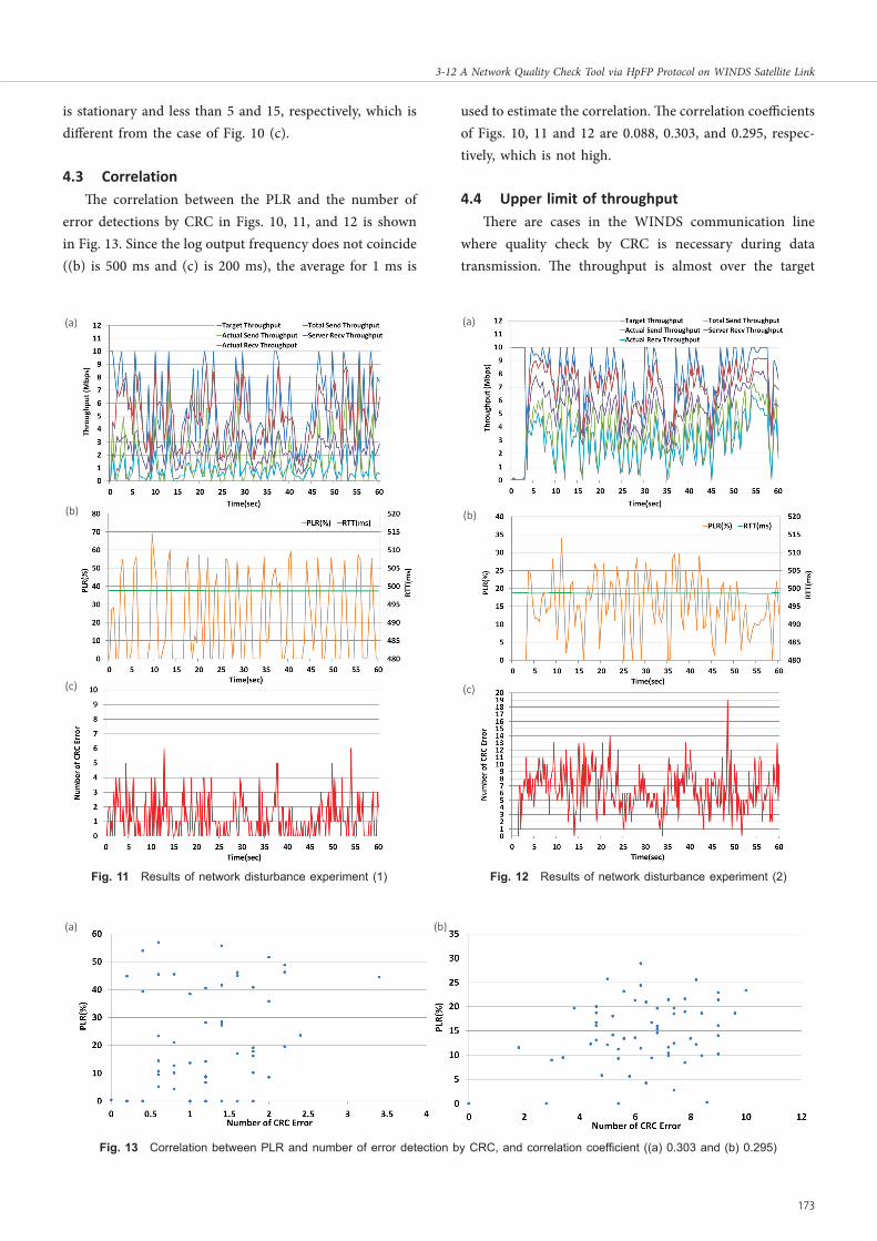
is stationary and less than 5 and 15, respectively, which is different from the case of Fig. 10 (c).
4.3 CorrelationThe correlation between the PLR and the number of
error detections by CRC in Figs. 10, 11, and 12 is shown in Fig. 13. Since the log output frequency does not coincide ((b) is 500 ms and (c) is 200 ms), the average for 1 ms is
used to estimate the correlation. The correlation coefficients of Figs. 10, 11 and 12 are 0.088, 0.303, and 0.295, respec-tively, which is not high.
4.4 Upper limit of throughputThere are cases in the WINDS communication line
where quality check by CRC is necessary during data transmission. The throughput is almost over the target
Fig.F 11 Results of network disturbance experiment (1) Fig.F 12 Results of network disturbance experiment (2)
Fig.F 13 Correlation between PLR and number of error detection by CRC, and correlation coefficient ((a) 0.303 and (b) 0.295)
(a)
(b)
(c)
(a)
(b)
(c)
(a) (b)
Title:J2017W-03-12.indd p173 2018/01/31/ 水 11:31:41
173
3-12 A Network Quality Check Tool via HpFP Protocol on WINDS Satellite Link

throughput, as shown in Fig. 10. When the quality of lines is high, it is possible to transmit data at 10 Mbps, conduct-ing CRC for all packets by hperf. In this section, we inves-tigate the maximum throughput of HpFP, which is transmissible during CRC for all packets by hperf.
During the time of CRC, the error is not detected. In Figs. 14, 15 and 16, throughputs of HpFP are shown for the cases of the target throughput of 100 Mbps and
1,400 Mbps, respectively. The format of these figures is the same as that of Figs. 8 (a) and (b). There is no essential difference between the results in Fig. 14 (a) and Fig. 15 (a), which are obtained in implementing CRC. In addition, the target throughput is achieved in both experiments, which are the same as in Fig. 10 (a). On the other hand, the ef-fective throughput in Fig. 16 (a) is much smaller than the target throughput, which is the same level of Figs. 14 (a) and 15 (b).
From these results, the possible maximum target throughput in the case of CRC for all packets during the data transmission in WINDS communication lines is 100 Mbps. The network condition may vary largely during even a small time interval for the WINDS with bent-pipe mode. Therefore, CRC is necessary to ensure the reliability of data transmission. The effective maximum data trans-mission rate is 100 Mbps for the case of data transmission by HpFP, which simultaneously confirmed the reliability of data arrival.
5 Conclusion
For ultra-high speed (> 1 Gbps), TCP/IP-based satellite communication protocols have been developed and various high-speed transmission is being attempted by improving TCP [11]–[14]. In general, RTT is large in the transmission link of geostationary orbit satellites or deep space investiga-tion satellite. The RTT for geostationary orbit satellites is
Fig.F 14 Case of no CRC at target throughput of 100 Mbps Fig.F 16 Case of CRC at target throughput of 1,400 Mbps
Fig.F 15 Case of CRC at target throughput of 100 Mbps
(a)
(b)
(a)
(b)
(a)
(b)
Title:J2017W-03-12.indd p174 2018/01/31/ 水 11:31:41
3 Ultra-High-Speed Satellite Communication Technology
174 Journal of the National Institute of Information and Communications Technology Vol. 64 No. 2 (2017)

500 ms and that to the moon surface is 2.6 sec. Moreover, the RTT for Mars is more than 13 minutes at maximum. As a result of higher bit error rate for the Ka band and Ku band due to weather conditions, compared to the X band or S band, packet loss increases in IP transmission. In a network with high latency and packet loss, it is well known that the throughput of TCP decreases largely and it is not easy to realize high-speed TCP transmission in satellite link.
We developed a novel protocol to realize high-speed data transfer in networks with high latency and packet loss, named HpFP [3][15][16]. The HpFP is designed based on UDP, and is a transmission protocol in transport layer to ensure the arrival of packets in the same manner as TCP. We measured transmission speed in the WINDS experi-ment and achieved an almost theoretically maximum rate of 1.6 Gbps for single connection. Moreover, we improved HpFP by implementing the CRC function. We detected an error rate for WINDS and discovered that the error detec-tion for all packets is possible if the throughput of WINDS is 100 Mbps.
In this paper, we investigated the correlation between the PLR and the number of error detections by CRC ob-tained for the case of throughput of 10 Mbps. As a result, the correlation between both was not so large, and there was a case that the number of error detections by CRC was low even when packet loss reached several tens of percent. To the contrary, there was a case where the PLR was 0% even when the case that the number of error detections by CRC was not zero. We checked the correlation estimation every second, and it is not a sufficient time period for more than ten thousand packets to arrive. In addition, the PLR is not influenced by multiple bit errors occurring in one packet. It implies that the correlation between both be-comes lower when bit error rate is higher. Therefore, we need to further discuss the evaluation method to derive the correlation. Since it is not possible to conduct measure-ments simultaneously in this system, we will discuss the effect of the quality of satellite link on data transmission by comparing BER measurement, CRC measurement, and PLR.
Acknowledgment
We thank to the members of Clealink Technology Co., Ltd. and Hotel Route-Inn Nakatsugawa Inter for their sup-port and cooperation. This paper is supported by the grants of Ministry of Internal Affairs and Communications
SCOPE (No. 165009001), and JSPS JP15 K06129, JP17 K00158, and JP17 HP8019.
ReReRenReR 1 K. Suzuki, M. Yahata, M. Kato, T. Watanabe, K. Hoshi, T. Okui, S. Yoshikawa,
M. Yoneda, Y. Arakawa, T. Asai, T. Takahashi, and M. Toyoshima, “16APSK/16QAM-OFDM 3.2Gbps RF signal directprocessing transmitter and receiver communication experiments using WINDS satellite,” IEICE Technical Report, vol.115, no.241, SAT2015-40, pp.137–140, Oct. 2015.
2 K. T. Murata, P. Pavarangkoon, K. Suzuki, K. Yamamoto, Y. Nagaya, T. Asai, T. Kan, N. Katayama, M. Yahata, K. Muranaga, T. Mizuhara, A. Takaki, and E. Kimura, “A high-speed data transfer protocol for geostationary orbit satel-lites,” in Proc. 2016 Int. Conf. Advanced Technologies for Communications (ATC), 2016, pp.425–430. doi: 10.1109/ATC.2016.7764819
3 K. T. Murata, P. Pavarangkoon, K. Yamamoto, Y. Nagaya, T. Mizuhara, A. Takaki, K. Muranaga, E. Kimura, T. Ikeda, K. Ikeda, and J. Tanaka, “A quality measure-ment tool for high-speed data transfer in long fat networks,” in Proc. 24th Int. Conf. Software, Telecommunications and Computer Networks (SoftCOM), 2016. doi: 10.1109/SOFTCOM.2016.7772111
4 P. Pavarangkoon, K. T. Murata, M. Okada, K. Yamamoto, Y. Nagaya, T. Mizuhara, A. Takaki, K. Muranaga, and E. Kimura, “Bandwidth utilization enhancement using high-performance and flexible protocol for INTELSAT satellite network,” in Proc. 7th IEEE Annu. Information Technology, Electronics and Mobile Communication Conf. (IEMCON), 2016. doi: 10.1109/IEMCON.2016.7746292
5 K. T. Murata, P. Pavarangkoon, K. Yamamoto, Y. Nagaya, K. Muranaga, T. Mizuhara, A. Takaki, O. Tatebe, and E. Kimura, “Multiple streams of UDT and HpFP protocols for high-bandwidth remote storage system in long fat network,” in Proc. 7th IEEE Annu. Information Technology, Electronics and Mobile Communication Conf. (IEMCON), 2016. doi: 10.1109/IEMCON.2016.7746276
6 K. T. Murata, K. Muranaga, K. Yamamoto, Y. Nagaya, P. Pavarangkoon, S. Satoh, T. Mizuhara, E. Kimura, O. Tatebe, M. Tanaka, and S. Kawahara, “Real-time 3D visualization of phased array weather radar data via concurrent processing in science cloud,” in Proc. 7th IEEE Annu. Information Technology, Electronics and Mobile Communication Conf. (IEMCON), 2016. doi: 10.1109/IEMCON.2016.7746347
7 K. T. Murata, P. Pavarangkoon, K. Yamamoto, Y. Nagaya, S. Satoh, K. Muranaga, T. Mizuhara, A. Takaki, and E. Kimura, “Improvement of real-time transfer of phased array weather radar data on long-distance networks,” 2016 International Conference on Radar, Antenna, Microwave, Electronics, and Telecommunications (ICRAMET), Jakarta, 2016, pp.22–27. doi: 10.1109/ICRAMET.2016.7849575
8 K. T. Murata, P. Pavarangkoon, K. Yamamoto, Y. Nagaya, N. Katayama, K. Muranaga, T. Mizuhara, A. Takaki, and E. Kimura, “An application of novel communications protocol to high throughput satellites,” in Proc. 7th IEEE Annu. Information Technology, Electronics and Mobile Communication Conf. (IEMCON), 2016. doi: 10.1109/IEMCON.2016.7746274
9 K. T. Murata, Y. Takeda, and M. Kikuchi, “A picture book of weather in Japan: Himawari-8 and ground-based photos,” Seibundo Shinkosha, 2017.
10 K. T. Murata, P. Pavarangkoon, A. Higuchi, K. Toyoshima, K. Yamamoto, K. Muranaga, Y. Nagaya, Y. Izumikawa, E. Kimura, and T. Mizuhara, “A web-based real-time and full-resolution data visualization for Himawari-8 satellite sensed images,” Earth Science Informatics, pp.1-21, Sept. 2017.
11 C. Caini and R. Firrincieli, “TCP Hybla: a TCP enhancement for heterogeneous networks,” International Journal of Satellite Communications and Networking, vol.22, no.5, pp.547–566, 2004. doi:10.1002/sat.799
12 L. Del Consuelo Hernandez Ruiz Gaytan, Z. Pan, J. Liu and S. Shimamoto, “Dynamic Scheduling for High Throughput Satellites Employing Priority Code Scheme,” in IEEE Access, vol. 3, pp. 2044–2054, 2015. doi: 10.1109/ACCESS.2015.2495226
13 M. Sarkar, K. Shukla and K. Dasgupta, “Delay resistant transport protocol for deep space communication,” International Journal of Communications, Network and System Sciences, vol.4, no.2, pp.122–132, 2011. doi:10.4236/ijcns.2011.42015
Title:J2017W-03-12.indd p175 2018/01/31/ 水 11:31:41
175
3-12 A Network Quality Check Tool via HpFP Protocol on WINDS Satellite Link
14 H. Obata, K. Taira, and K. Ishida, “Implementation and evaluation of TCP-STAR: TCP congestion control method for satellite Internet,” IEICE Transactions (Japanese Edition), J90, pp.566–576, 2007
15 K. T. Murata, Y. Nagaya, and T. Nagatsuma, “Science big data and science cloud,” Tokai Joho Tsushin Kondankai Newsletter, no.107, 2015.
16 K. T. Murata, Y. Nagaya, and T. Mizuhara, “High-speed data transfer protocol for high-function remote controls in IoT/M2M era,” Radio Engineering and Electronics Association Newsletter FORN, no.312, 2016.
Ken T. MURATA, Dr. Eng.Research Executive Director, Social Innovation Unit ICT Testbed Research and Development Promotion CenterInformation communication technology
Kazunori YAMAMOTOTechnical Researcher, Social Innovation Unit ICT Testbed Research and Development Promotion CenterSpace information engineering
Praphan PAVARANGKOON, Ph.D.Researcher, Social Innovation Unit ICT Testbed Research and Development Promotion CenterOptical networks, High-speed data transfer protocol, Internet of things (IoT)
Kenji SUZUKISenior Researcher, Space Communications Laboratory, Wireless Networks Research CenterSatellite communication
Toshio ASAI Space Communications Laboratory, Wireless Networks Research CenterSatellite communications system
Tomoshige KAN, Dr. Eng.Researcher, Space Communications Laboratory, Wireless Networks Research CenterSatellite communication propagation
Kazuya MURANAGASystems Engineering Consultants Co., LTD.Real-time technology
Takamichi MIZUHARACLEALINKTECHNOLOGY Co.,Ltd.LFN protocol, Cryptography communication, IP realtime protocol
Yuya KAGEBAYASHICLEALINKTECHNOLOGY Co.,Ltd.LFN protocol, Coding/ Decoding
Yasunori KAKIZAWACLEALINKTECHNOLOGY Co.,Ltd.LFN protocol, Machine learning
Masatomo YAHATASpace Systems Division, Integrated Systems DepartmentSatellite communication
Title:J2017W-03-12.indd p176 2018/01/31/ 水 11:31:41
3 Ultra-High-Speed Satellite Communication Technology
176 Journal of the National Institute of Information and Communications Technology Vol. 64 No. 2 (2017)