3-colour display rohs electromagnetic digital flow …sensor unit monitor unit 3-colour display...
TRANSCRIPT
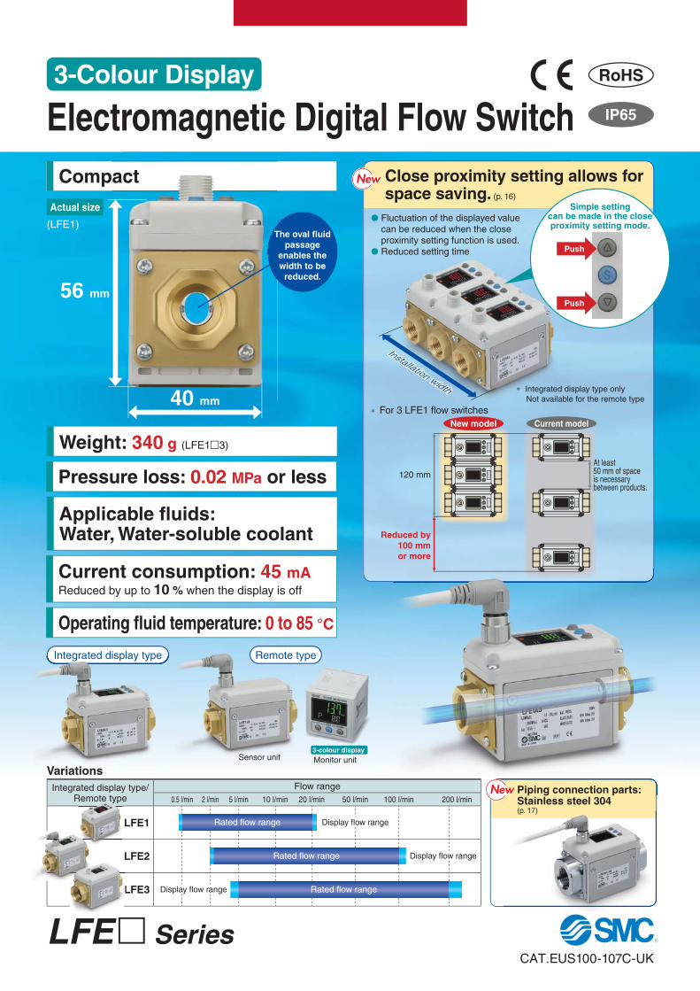
Compact Close proximity setting allows for space saving. (p. 16)
Pressure loss: 0.02 MPa or less
Weight: 340 g (LFE1�3)
Current consumption: 45 mAReduced by up to 10 % when the display is off
Applicable fl uids: Water, Water-soluble coolant
Operating fl uid temperature: 0 to 85 °C
act
Installation width
56 mm
40 mm
� Fluctuation of the displayed value can be reduced when the close proximity setting function is used.
� Reduced setting time
∗ Integrated display type only
Not available for the remote type
Integrated display type/Remote type
Flow range
0.5 l/min 2 l/min 5 l/min 10 l/min 20 l/min 50 l/min 100 l/min 200 l/min
LFE1
LFE2
LFE3
Variations
Rated fl ow range Display fl ow range
Rated fl ow range Display fl ow range
Rated fl ow rangeDisplay fl ow range
Remote tyypePiping connection parts:Stainless steel 304(p. 17)
The oval fl uid
passage
enables the
width to be
reduced.
Actual size Simple settingcan be made in the close proximity setting mode.
Sensor unit Monitor unit
3-colour display
Integrated display type Remote type
(LFE1)
At least50 mm of spaceis necessarybetween products.
120 mm
Reduced by
100 mm
or more
Variations
Integrated display type
∗ For 3 LFE1 fl ow switches
Push
Push
New model Current model
NewNew
NewNew
CAT.EUS100-107C-UK
LFE� Series
Electromagnetic Digital Flow Switch
3-Colour Display RoHS

�Default flow direction (Normal flow)
Instantaneous flow rate is displayed.
The parameters below can be set.�Flow direction can be changed after installation.
flow direction
Normal flow(Left to right)
Reverse flow(Right to left)
IN
OUT
IN
OUT
LFE� Series
¡Set value ¡Flow direction ¡Accumulated value ¡Line name¡Peak/Bottom value
Electromagnetic Digital Flow Switch
Reverse flow error displayReverse flow error (Code LLL)
Reverseflow
Reverse flow can be detected.
Repeatability: ±1.5 % F.S. (Analogue output)
Flow direction can be changed after installation.
The display can be adjusted to zero.
A zero-reset setting is available.
3-colour/2-screen display
NewNew
∗ Integrated displaytype only
Flow control for water-solublecoolant
Flow control for cooling waterfor metal molds
Application Examples
Measure the volume flow of inductive liquids by applying Faraday’s
law of induction: “when a conductive object is moved through a
magnetic field, an electromotive force will be generated.”
The electromotive force (E) is proportional to the fluid velocity (V) multiplied by the magnetic flux density (B).
The volume flow is calculated by converting the measured electromotive force (E).
An oval fluid passage is used to improve the magnetic flux density generated by small amounts of current.
Principle
x density (B).
current.
Electrode
Electromotive force (E)
Magnetic flux density (B)
Fluid velocity (V)
Fluid
CoilFaraday’s law of induction
Flow control for pressurisedcooling water for welding guns
Fluid passage/Piping
1

C O N T E N T S
Flow Switch for Fluid Variations
PVC piping
type
∗1 For the remote type monitor unit, only the front side is IP65 compliant. The other parts are IP40 compliant.
Series20 0.5 5 10 20 30 40 50 100 200150 250
Rated flow range [l/min]Smallestsettable
increment
Detection
methodEnclosure∗1 Display
Applicable
fluid
Electro-
magneticIP65
3-colour
display
Water,
Water-soluble
coolant
0.1 l/min
0.5 l/min
1 l/min
IP651-colour
display
0.05 l/min
0.1 l/min
0.5 l/min
PF2D
Karman
vortexIP65
3-colour
display
Water,
Ethylene glycol
aqueous
solution
0.01 l/min
0.1 l/min
0.1 l/min
1 l/min
2 l/min
PF3W
Karman
vortex
Karman
vortex
IP653-colour
display
Water,
Ethylene glycol
aqueous
solution
1 l/min
2 l/min
0.5 20
0.5 4
0.4 4
1.8 20
4 40
2.5 100
10 100
50 250
10 100
30 250
2 16
5 200
5 40
LFE
3-Colour Display Electromagnetic Digital Flow SwitchLFE Series
How to Order p. 3
Specifications (Integrated Display Type) p. 4
Specifications (Remote Type Sensor Unit) p. 5
Flow Rate Characteristics (Pressure Loss) p. 6
Internal Circuits and Wiring Examples p. 7
Parts Description p. 8
Fluid Passage Structure p. 8
Dimensions p. 9
3-Colour Display Digital Flow MonitorLFE0 Series
How to Order p. 10
Specifications (Remote Type Monitor Unit) p. 11
Internal Circuits and Wiring Examples p. 12
Parts Description (Remote Type Monitor Unit) p. 13
Dimensions p. 14
Function Details p. 15
Made to Order p. 17
Specific Product Precautions p. 18
Safety Instructions Back cover
······································
···
···
····
·····
·································
························
········································
····································
······
····
···
······································
·····················
·······················
····
·········
Deionised
water
(pure water),
Liquids which
do not
corrode
nor erode
fluoropolymer
2

Made to Order (Refer to p. 17.)
Thread type
Symbol Description
X8 Piping connection parts: Stainless steel 304
Symbol Type
— Rc
N NPT
F G
The close proximity setting and zero-reset setting functions are only
available for the integrated display type.
For the remote type sensor unit, the close proximity setting and zero-
reset setting functions cannot be used.
∗ When using this switch in
combination with an LFE 0 ,
select output specifi cation J.
Option/Part No.
When only optional parts are required, order with the part numbers listed below.
LFERated fl ow range
Integrated display type
Output specifi cations
Output specifi cations
Electromagnetic Digital Flow Switch
3-Colour Display
LFERemote type sensor unit
Port size
1
1 3J
3A
How to Order
Option
∗1 Options 4, 5, 6, and 7 cannot be selected when the output
specifi cation is J or K.
Reference: 1 [l/min] = 0.2642 [gal/min]
1 [gal/min] = 3.785 [l/min]
LFE SeriesRoHS
Integrated
display type
Remote type
sensor unit
Remote type
monitor unit
For details, refer
to p. 10.
Symbol OUT
J Analogue 1 to 5 V
K Analogue 4 to 20 mA
Symbol Rated fl ow range
1 0.5 to 20 l/min
2 2.5 to 100 l/min
3 5 to 200 l/min
Symbol OUT1 OUT2
A NPN NPN
B PNP PNP
C NPN Analogue 1 to 5 V
D NPN Analogue 4 to 20 mA
Symbol Port sizeApplicable model
LFE1 LFE2 LFE33 3/8 � — —
4 1/2 � — —
6 3/4 — � —
8 1 — — �
SymbolLead wire and M12
connector (Length 3 m)Bracket Display unit
— � — l/min
1 — — l/min
2 � � l/min
3 — � l/min
4∗1 � — gal/min
5∗1 — — gal/min
6∗1 � � gal/min
7∗1 — � gal/min
Option Part no. Note Weight
Lead wire and M12 connector LFE-1-A3 Lead wire length 3 m Approx. 175 g
Option Part no. Note Weight
Bracket
LFE-1-D Tapping screw for LFE1 (3 x 10), 4 pcs. Approx. 45 g
LFE-2-D Tapping screw for LFE2 (3 x 10), 4 pcs. Approx. 70 g
LFE-3-D Tapping screw for LFE3 (3 x 10), 4 pcs. Approx. 70 g
Remote type
3

∗1 Refer to the Applicable Fluids List on p. 20.∗2 0 l/min is displayed when the fl ow is less than zero-cut fl ow.∗3 When fl uids with high temperature are used, the operating pressure range and proof pressure will be reduced. (For details, refer to the Operating Pressure Range on p. 6.)∗4 Cleared when the power supply is turned off. Hold function can be selected. (Interval of 2 or 5 minutes can be selected.) If the 5 minutes interval is selected,
the life of the memory element (electronic parts) is limited to 1 million times. (If energised for 24 hours, life is calculated as 5 minutes x 1 million = 5 million minutes = about 9.5 years.) Therefore, if using the hold function, calculate the memory life for your operating conditions, and use within this life.
∗5 The response time when the set value is 63 % in relation to the step input.∗6 The response time until the set value reaches 63 % in relation to the step input. There might be a 0.05 seconds delay at response time of 0.25 s or 0.5 s
due to the timing of internal processing.∗7 The stability of display and analogue output is improved by increasing the response time setting. (For details, refer to the Stability on p. 6.)∗8 When options are used, add the weight of the optional parts.∗9 Enclosure is for digital fl ow switch with lead wire and M12 connector.∗10 Piping port is grounded to DC(–)/blue line. Power supply with positive ground cannot be used. (Refer to Figure 1.)
Please consult SMC if the product is used for positive ground environment.∗11 The rated fl ow range is a fl ow range in which the product specifi cations (accuracy and repeatability) of the sensor are satisfi ed. The correct fl ow value
may not be indicated outside the fl ow range.
Specifi cations (Integrated Display Type)
DC (+)
DC (−)DC (+)
DC (+)
DC (−)DC (−) part is connected to DC (–).part is connected to DC (–).
If used with power supply with positive ground,
the metal part will short.
Piping Piping
Figure 1
Model LFE1 LFE2 LFE3Applicable fl uid∗1 Water, Conductive fl uids which do not corrode the fl uid contact materials.∗1
Applicable fl uid conductivity∗1 5 μS/cm or more (micro siemens)
Detection method Electrostatic capacity
Ground∗10 Negative ground
Rated fl ow range∗11 0.5 to 20 l/min 2.5 to 100 l/min 5 to 200 l/min
Display fl ow range 0.4 to 24.0 l/min 2.0 to 120.0 l/min 4 to 240 l/min
Set fl ow range 0.4 to 24.0 l/min 2.0 to 120.0 l/min 4 to 240 l/min
Zero-cut fl ow∗2 0.4 l/min 2.0 l/min 4 l/min
Smallest settable increment 0.1 l/min 0.5 l/min 1 l/min
Accumulated volume per pulse (Pulse width: 50 ms) 0.1 L/pulse 0.5 L/pulse 1 L/pulse
Operating fl uid temperature ∗3 0 to 85 °C (with no freezing and condensation)
Display units Instantaneous fl ow rate l/min, Accumulated fl ow L
Repeatability Displayed values: ±2 % F.S. Analogue output: ±1.5 % F.S.
Temperature
characteristics
Ambient temperature ±5 % F.S. (25 °C reference)
Fluid temperature ±5 % F.S. (25 °C reference)
Operating pressure range∗3 0 to 1 MPa
Proof pressure∗3 2 MPa
Accumulated fl ow range∗499999999.9 L 999999999 L
by 0.1 L by 1 L
Switch output NPN or PNP open collector output
Maximum load current 80 mA
Maximum applied voltage 28 VDC
Internal voltage drop NPN: 1 V or less (at load current of 80 mA) PNP: 1.5 V or less (at load current of 80 mA)
Response time∗5∗7 0.25 s/0.5 s/1 s/2 s/5 s
Output protection Short-circuit protection
Output mode Select from hysteresis mode, window comparator mode, accumulated output mode, or accumulated pulse output mode.
Analogue
output
Response time∗6∗7 0.25 s/0.5 s/1 s/2 s/5 s
Voltage output Output voltage: 1 to 5 V Output impedance: 1 kΩCurrent output Output current: 4 to 20 mA Max. load impedance: 600 Ω
Hysteresis Variable
Display method2-screen (Main screen: 4-digit, 7-segment, 2-colour, Red/Green; Sub screen: 6-digit, 11-segment, White)
Display values updated 5 times per second
Status LED’s Output 1, Output 2: Orange
Power supply voltage 24 VDC ±10 %
Current consumption 45 mA or less (Load current is not included.)
Environmental
resistance
Enclosure∗9 IP65
Operating temperature range 0 to 50 °C (with no freezing and condensation)
Operating humidity range Operating, Storage: 35 to 85 % R.H. (with no condensation)
Standards and regulations CE marking, RoHS
Fluid contact materials PPS, FKM, Brass
Port size 3/8 (10A) 1/2 (15A) 3/4 (20A) 1 (25A)
Weight (Body)∗8 Approx. 340 g Approx. 400 g Approx. 520 g Approx. 680 g
For the flow switch precautions, refer to
the Operation Manual on the SMC website.
4
3-Colour Display Electromagnetic Digital Flow Switch LFE Series

Analogue Output
∗1 Refer to the Applicable Fluids List on p. 20.
∗2 When fl uids with high temperature are used, the available pressure range will be reduced. (For details, refer to the Operating Pressure Range on p. 6.)
∗3 The response time until the set value reaches 63 % in relation to the step input.
∗4 When options are used, add the weight of the optional parts.
∗5 Piping port and the metal part of the body are grounded to DC(–)/blue line. Power supply with positive ground cannot be used. Please consult SMC if
the product is used for positive ground environment.
∗6 The rated fl ow range is a fl ow range in which the product specifi cations (accuracy and repeatability) of the sensor are satisfi ed. The correct fl ow value
may not be indicated outside the fl ow range.
Specifi cations (Remote Type Sensor Unit/Body) ∗ Refer to p. 10 for the monitor unit specifi cations.
Flow/Analogue output
Flow rate
Output
A
C
B
0 Min.
rated flow
Max.
rated flow
Outside the range
Model LFE1 LFE2 LFE3Applicable fl uid∗1 Water, Conductive fl uids which do not corrode the fl uid contact materials.∗1
Applicable fl uid conductivity∗1 5 μS/cm or more (micro siemens)
Detection method Electrostatic capacity
Ground∗5 Negative ground
Rated fl ow range∗6 0.5 to 20 l/min 2.5 to 100 l/min 5 to 200 l/min
Operating fl uid temperature∗2 0 to 85 °C (with no freezing and condensation)
Repeatability Analogue output: ±1.5 % F.S.
Temperature
characteristics
Ambient temperature ±5 % F.S. (25 °C reference)
Fluid temperature ±5 % F.S. (25 °C reference)
Operating pressure range∗2 0 to 1 MPa
Proof pressure∗2 2 MPa
Analogue
output
Response time∗3 0.5 s
Voltage output Output voltage: 1 to 5 V Output impedance: 1 kΩCurrent output Output current: 4 to 20 mA Max. load impedance: 600 Ω
Power supply voltage 24 VDC ±10 %
Current consumption 42 mA or less (Load current is not included.)
Environmental
resistance
Enclosure IP65
Operating temperature range 0 to 50 °C (with no freezing and condensation)
Operating humidity range Operating, Storage: 35 to 85 % R.H. (with no condensation)
Standards and regulations CE marking, RoHS
Fluid contact materials PPS, FKM, Brass
Port size 3/8 (10A) 1/2 (15A) 3/4 (20A) 1 (25A)
Weight (Body)∗4 Approx. 335 g Approx. 395 g Approx. 515 g Approx. 675 g
A B C
Voltage output 1 V 1.1 V 5 V
Current output 4 mA 4.4 mA 20 mA
ModelRated fl ow [l/min]
Minimum Maximum
LFE1 0.5 20
LFE2 2.5 100
LFE3 5 200
For the flow switch precautions, refer to
the Operation Manual on the SMC website.
5
LFE Series

Flow Rate Characteristics (Pressure Loss)
Operating Pressure RangeStability
[mm]
Straight Piping Length and Accuracy (Reference Value)
• The smaller the piping size, the more the product
is affected by the straight piping length.
The straight piping length shall be 5 times (5D) or
more of the piping size to achieve the stable
measurement.
∗ Stability indicates the fl uctuation width of the display or analogue output.
When fl uids with high temperature are used,
the operating pressure range will be reduced.
Operate within the range mentioned above. The
proof pressure is double the operating pressure
range.
∗ Stability is improved by increasing the response time setting.
±0
±0.5
±1.0
±1.5
±2.0
±2.5
±3.0
±3.5
±4.0
Response time [s]
Sta
bili
ty [
% F
.S.]
0.25 0.5 1 2 5
1.1
1
0.9
0.8
0.7
0.6
0.5
0.4
0.3
0.2
0.1
00 10 20 30 40 50 60 70 80 90
Fluid temperature [°C]
Pre
ssure
[M
Pa
]
Operating range
LFE1 LFE2 LFE3
Flow value [l/min]
Pre
ssure
loss [
MP
a]
Flow value [l/min]
Pre
ssure
loss [
MP
a]
Flow value [l/min]
Pre
ssure
loss [
MP
a]
0
0.005
0.01
0.015
0.02
0 50 100 150 2000
0.005
0.01
0.015
0.02
0 5 10 15 200
0.005
0.01
0.015
0.02
0 20 40 60 80 100
[Measurement conditions]
Fluid: Tap water
Pressure: 0.2 MPa 0 D 2D 3D 4D 5D
Straight piping length
Accu
racy c
ha
ng
e [%
F.S
.]
Accuracy changeStraight piping
length
[Port size]
LFE1: 3/8 inch
LFE2: 3/4 inch
LFE3: 1 inch
3
2
1
0
Straight piping
length
ModelStraight piping length
D 5DLFE1 11 55
LFE2 21 105
LFE3 27 135
6
3-Colour Display Electromagnetic Digital Flow Switch LFE Series

Accumulated pulse output wiring examples
Internal Circuits and Wiring Examples (Integrated Display Type)
NPN 2 output typeLFE�A���
NPN + Analogue output typeLFE�C���
NPN + Analogue output typeLFE�D���
NPN 2 output typeLFE�A���
NPN + Analogue output typeLFE�C���/LFE�D���
PNP 2 output typeLFE�B���
PNP 2 output typeLFE�B���
∗ When accumulated pulse output is selected, the indicator light is turned off.
Internal Circuits and Wiring Examples (Remote Type Sensor Unit)
Analogue output typeLFE�J��� (Voltage output type)LFE�K��� (Current output type)
Brown DC (+)
Black OUT1
White OUT2
Blue DC (−)
24 VDC
Load
Load
Main
circuit
Max. 28 V, 80 mAInternal voltage drop 1 V or less
24 VDC
Brown DC (+)
Black OUT1
White OUT2
Blue DC (−)
Load
Load
Main
circuit
Max. 80 mAInternal voltage drop 1.5 V or less
Brown DC (+)
Black OUT1
Blue DC (−)
24 VDCWhite Analogue output
Load
Load
Main
circuit
Max. 28 V, 80 mAInternal voltage drop 1 V or lessC: Analogue output 1 to 5 V
Output impedance 1 kΩD: Analogue output 4 to 20 mA
Load impedance 50 to 600 Ω
50 ms
0 V
50 ms
or
Black OUT1
White OUT2 (LFE�A��� only)
Blue DC (−)
Load
Load
Max. 28 V, 80 mA
Max. 80 mA
Brown DC (+)
Black OUT1
White OUT2
Load
Load
50 ms
0 V
50 ms
or
Brown DC (+)
N.C.
Blue DC (−)
24 VDCWhite Analogue output
Load
Ma
in c
ircu
it
∗ Do not connect N.C.
7
LFE Series

DOWN button
SET button
UP button
Main screen
(2-colour display)
Output display
(Status LED’s)
Sub screen Unit display
qr
we e
w
r
Parts Description
Fluid Passage Structure
Body
Display
Display
Lead wire and M12 connector
(4 pins)
Piping port
Connector
Piping port
Bracket
(Option)
Description Function
Connector M12 connector for electrical connections
Lead wire and
M12 connector
Cable for supplying power to the product and for receiving
output
Piping port For piping connections
Display Displays the fl ow, set values, and error information
Bracket Mounting bracket for installing the product
Description Function
Main screen (2-colour display) Displays the fl ow value, setting mode, and error codes
Sub screen
Displays the accumulated fl ow, set value, peak/bottom value, fl ow direction,
line names, and close proximity setting values
In setting mode, the set status is displayed. (For details, refer to p. 15.)
Output display (Status LED’s) Displays the output condition of OUT1 and OUT2 (When ON: Orange light turns on)
UP button Selects the mode and the display shown on the sub screen or increases the ON/OFF set value
SET button Used to make changes in each mode and to enter the set value
DOWN button Selects the mode and the display shown on the sub screen or decreases the ON/OFF set value
Unit display Indicates the unit currently selected
No. Description Material
1 Pipe PPS
2 O-ring FKM
3 Attachment Brass
4 Spacer FKM
8
3-Colour Display Electromagnetic Digital Flow Switch LFE Series

(45)
(30)
(31)
(25)
(31)
(24)
Brown
White
Blue
Black
Ø 15
3: Blue
2: White
M12
1: Brown
4: Black
Ø 6
(3000)
Dimensions
Cable Specifi cations
Integrated display type LFE1/2/3
Lead wire and M12 connector
∗ If you are installing directly, choose the self tapping screw screw-in depth is to 8 mm. Tighten the screw with a torque of 0.7 to 0.8 N·m.
(U) (U)
Without bracket (Bottom view)
Bracket thickness is approx. 1.6 mm.
4 x O
L
K
MN
QP
∗ For integrated display type
∗ Dimensions are the same as those for integrated display type.
Note) The electrical entry for lead wire with M12 connector does
not rotate and is limited to only one entry direction.
IN OUT
A
B
Remote type sensor unit LFE1/2/3
Width across flats H
2 x Port size
I
J
C
D
E
F
G
1.4∗
4 × TR
S
Model Port size A B C D E F G H I J K L M N O P Q R S T ULFE1�3� 3/8 90 73 40 23.5 56 83 89 24 6 1.6 96 87 48 39 4.6 12 11.5 52 28 Ø 2.5 depth 8.5 2
LFE1�4� 1/2 104 73 40 23.5 56 83 89 28 6 1.6 96 87 48 39 4.6 12 11.5 52 28 Ø 2.5 depth 8.5 2
LFE2� 3/4 105 78 50 29 67 94 100 35 6 1.6 115 106 62 53 4.6 9.5 14 56 38 Ø 2.5 depth 8.5 2.6
LFE3� 1 120 90 55 32 73 100 106 41 6 1.6 115 106 62 53 4.6 3.5 20 68 43 Ø 2.5 depth 8.5 2.6
Pin no. Pin description Wire colour
1 DC (+) Brown
2 OUT 2 White
3 DC (−) Blue
4 OUT 1 Black
ConductorNominal cross section area AWG21
External diameter Approx. 0.9 mm
Insulator
Material Non-lead heat resistant PVC
External diameter Approx. 1.7 mm
Colours Brown, White, Black, Blue
Sheath Material Non-lead heat and oil resistant PVC
Finished external diameter Ø 6
9
LFE Series

LFE A0Type
∗ For the remote type sensor unit, select
the analogue output 1 to 5 V type.
Applicable sensors: LFE�J���∗ Does not support the close proximity
setting/zero-reset setting functions
Output specifi cations
The lead wire does not come connected, but it is shipped together with the product.
Lead wire
The connector does not come connected, but it is shipped together with the product.
Option 2
Option 1
Option/Part No.
When only optional parts are required, order with the part numbers listed below.
Remote type monitor unit/Display unit
M V C
How to Order
Digital Flow Monitor
3-Colour Display
LFE0 SeriesRoHS
Power supply/output connection lead wire
ZS-40-W
Sensor connector
(e-con)
Panel mount adapter
Mounting screw (M3 x 8L)
(Accessory)Waterproof seal
(Accessory) Panel
Waterproof seal
(Accessory)
Mounting screw (M3 x 8L)
(Accessory)
Panel mount adapter
Front protective cover
Panel
0 Remote type monitor unit
Symbol OUT1 OUT2
A NPN NPN
B PNP PNP
C NPN Analogue 1 to 5 V
D NPN Analogue 4 to 20 mA
—
With power supply/output connection lead wire (2 m)
N Without power supply/output connection lead wire
Symbol Instantaneous fl ow rate Accumulated fl ow
M l/min L
G gal/min gal
— Without connector
C
Sensor connector (1 pc.)
— None
T
Panel mount adapter
V
Front protective cover + Panel mount adapter
Description Part no. Note
Panel mount adapter ZS-26-B With waterproof seal, mounting screw
Front protective cover + Panel mount adapter ZS-26-C With waterproof seal, mounting screw
Front protective cover only ZS-26-01 Separately order panel mount adapter, etc.
Power supply/output connection lead wire ZS-40-W Lead wire length 2 m
Sensor connector (e-con) ZS-28-C-5 1 pc.
Lead wire with connector for copying ZS-40-Y Connect up to 10 slave units
∗ G: Made to order
Reference: 1 [l/min] 0.2642 [gal/min]
1 [gal/min] 3.785 [l/min]
10

Specifi cations (Remote Type Monitor Unit)
∗1 Cleared when the power supply is turned off. Hold function can be selected. (Interval of 2 or 5 minutes can be selected.) If the 5 minutes interval is selected, the life of the memory element (electronic parts) is limited to 1 million times. (If energised for 24 hours, life is calculated as 5 minutes x 1 million = 5 million minutes = about 9.5 years.) Therefore, if using the hold function, calculate the memory life for your operating conditions, and use within this life.
∗2 The response time when the set value is 63 % in relation to the step input.∗3 The response time until the set value reaches 63 % in relation to the step input.
Analogue Output
Flow/Analogue output
0
Output
Min.
rated flow
Max.
rated flow
Flow rate
A
C
B
Outside the range
Model LFE0
Display fl ow range0.4 to 24.0 l/min
(Flow under 0.4 l/min is displayed as “0.00”)2.0 to 120.0 l/min
(Flow under 2.0 l/min is displayed as “0.0”)4 to 240 l/min
(Flow under 4 l/min is displayed as “0.0”)
Set fl ow range 0.4 to 24.0 l/min 2.0 to 120.0 l/min 4 to 240 l/min
Smallest settable increment 0.1 l/min 0.5 l/min 1 l/min
Accumulated volume per pulse 0.1 L/pulse 0.5 L/pulse 1 L/pulse
Display units Instantaneous fl ow rate l/min, Accumulated fl ow L
Accuracy Displayed values: ±0.5 % F.S., Analogue output: ±0.5 % F.S.
Repeatability ±0.5 % F.S.
Temperature characteristics ±0.5 % F.S. (25 °C reference)
Accumulated fl ow range∗1 99999999.9 L 999999999 L
by 0.1 L by 1 L
Switch output NPN or PNP open collector output
Maximum load current 80 mA
Maximum applied voltage 28 VDC
Internal voltage drop NPN: 1 V or less (at load current of 80 mA) PNP: 1.5 V or less (at load current of 80 mA)
Response time∗2 0.5 s/1 s/2 s/5 s
Output protection Short-circuit protection
Output
mode
Flow rate Select from hysteresis mode, window comparator mode, accumulated output mode, or accumulated pulse output mode.
Temperature Select from hysteresis mode or window comparator mode.
Analogue
output
Response time∗3 0.5 s/1 s/2 s/5 s (linked with the switch output)
Voltage output Output voltage: 1 to 5 V Output impedance: 1 kΩCurrent output Output current: 4 to 20 mA Max. load impedance: 600 Ω
Hysteresis Variable
Input/output Input for copy mode
Display method 2-screen (Main screen: 4-digit, 7-segment, 2-colour, Red/Green; Sub screen: 6-digit, 11-segment, White) Display values updated 5 times per second
Status LED’s Output 1, Output 2: Orange
Power supply voltage 24 VDC ±10 %
Current consumption 50 mA or less
Connection Power supply output 5P connector, sensor connection 4P connector (e-con)
Environmental
resistance
Enclosure IP40 (Only front face of the panel is IP65 when panel mount adapter and waterproof seal of optional parts are used.)
Operating temperature range 0 to 50 °C (with no freezing and condensation)
Operating humidity range Operating, Storage: 35 to 85 % R.H. (with no condensation)
Withstand voltage 1000 VAC for 1 minute between terminals and housing
Insulation resistance 50 MΩ or more (500 VDC measured via megohmmeter) between terminals and housing
Standards and regulations CE marking, RoHS
Weight
Without power supply/output
connection lead wire50 g
With power supply/output
connection lead wire100 g
A B C
Voltage output 1 V 1.1 V 5 V
Current output 4 mA 4.4 mA 20 mA
Connectedsensor
Rated fl ow [l/min]
Minimum Maximum
LFE1 0.5 20
LFE2 2.5 100
LFE3 5 200
For the flow switch precautions, refer to
the Operation Manual on the SMC website.
11
LFE0 Series

Internal Circuits and Wiring Examples
NPN + Analogue output type LFE0CNPN + Analogue output type LFE0D
PNP 2 output type LFE0B
Sensor input circuit
Accumulated pulse output wiring examples
NPN 2 output type LFE0ANPN + Analogue output type LFE0C/LFE0D
PNP 2 output type LFE0B
∗ When accumulated pulse output is selected, the indicator light is turned off.
Brown DC (+)
Black OUT1
White OUT2
Blue DC (−)
24 VDC
Load
Load
Grey COPY
NPN 2 output type LFE0A
Main
circuit
24 VDC
Brown DC (+)
Black OUT1
White OUT2
Grey COPY
Blue DC (−)
Load
LoadMain
circuit
Brown DC (+)
Black OUT1
Blue DC (−)
24 VDCWhite Analogue output
Grey COPYLoad
Load
Main
circuit
r
e
w
q
1 to 5 V (Flow value) White
DC (−) Blue
N.C.
DC (+) Brown
Main
circuit
∗ Do not connect N.C.
50 ms
0 V
50 ms
or
Black OUT1
White OUT2 (LFE0A only)
Blue DC (−)
Load
Load
Brown DC (+)
Black OUT1
White OUT2
Load
Load
50 ms
0 V
50 ms
or
12
3-Colour Display Digital Flow Monitor LFE0 Series

Parts Description (Remote Type Monitor Unit)
Sensor connector
Power supply/output connection lead wire
Cable Specifi cations
∗1 When using the lead wire and M12 connector included with the LFE�J series.
Do not connect black.
Sensor connector
Power supply/output connection lead wire
Main screen (2-colour display)
Output display
(Status LED’s)
Sub screen
UP button SET button DOWN button
Unit display
12
34
r
q
ew
1234
5
Pin no.
Grey COPYWhite OUT2Black OUT1Blue DC(−)
Brown DC(+)2000
Description Function
Main screen (2-colour display) Displays the fl ow value, setting mode, and error codes
Sub screenDisplays the accumulated fl ow, set value, peak/bottom value, fl uid temperature, and
line names. In setting mode, the set status is displayed. (For details, refer to p. 15.)
Output display (Status LED’s) Displays the output condition of OUT1 and OUT2. (When ON: Orange light turns on)
Unit display Indicates the unit currently selected
UP button Selects the mode and the display shown on the sub screen or increases the ON/OFF set value
SET button Used to make changes in each mode and to enter the set value
DOWN button Selects the mode and the display shown on the sub screen or decreases the ON/OFF set value
Pin no. Terminal Connector no. Lead wire colour ∗1
q DC (+) 1 Brown
w N.C./IN 2 Not used
e DC (−) 3 Blue
r INPUT 4 White (Flow sensor 1 to 5 V input)
ConductorNominal cross section area AWG26
External diameter Approx. 0.5 mm
Insulator
Material Cross-linked vinyl
External diameter Approx. 1.0 mm
Colours Brown, Blue, Black, White, Grey
Sheath Material Oil and heat resistant vinyl
Finished external diameter Ø 3.5
13
LFE0 Series

Panel fi tting dimensions
Applicable panel thickness:
0.5 to 8 mm (Without waterproof seal)
0.5 to 6 mm (With waterproof seal)
Front protective cover + Panel mount adapter
Dimensions
NC/IN
40.1 (7.5)
2.5
�3
6.8
640
40
Power supply/output connector (5P)
Sensor connector (4P)
Front protective cover
Waterproof sealPanel
Panel mount adapter
47
�4
2.4
(2)9.4
46
.4
53
37.5 +0.1−0.2
37.5
+0
.1−
0.2
48 or more
55 o
r m
ore
4 x
R1 or
less
14
3-Colour Display Digital Flow Monitor LFE0 Series

� Display colour
The display colour can be selected for each
output condition. The selection of the dis-
play colour provides visual identifi cation of
abnormal values. (The display colour de-
pends on OUT1 settings.)
� Setting of response time
The response time can be selected according to
the application. (The default setting is 1 second.)
The fl uctuation of the displayed value can be re-
duced by setting a slower response time. If you
need faster detection of problems such as leak-
age of tip cooling water for welding guns, switch
output or analogue output can be made faster
by setting a faster response time. In this case,
widen the hysteresis to prevent the chattering of
the switch output.
� Output operation
The output operation can be selected from the following:
Output (hysteresis mode and window comparator mode) correspond-
ing to instantaneous fl ow rate, output corresponding to accumulated
fl ow, or accumulated pulse output.
∗ At the time of shipment from the factory, it is set to hysteresis mode and
normal output.
� Forced output function
The output is turned ON/OFF compulsorily when starting the system
or during maintenance. This enables the confi rmation of the wiring
and prevents system errors due to unexpected output.
For the analogue output type, the output will be 5 V or 20 mA for ON
and 1 V or 4 mA for OFF.
∗ Also, the increase or decrease of the fl ow will not change the on/off
status of the output while the forced output function is activated.
� Accumulated value hold functionThe accumulated value is not cleared even when the power supply is
turned off. The accumulated value is memorised every 2 or 5 minutes
during measurement and continues from the last memorised value when
the power supply is turned on again.
The life time of the memory element is 1 million access times. Take this
into consideration before using this function.
� Switching of fl ow direction (∗ Integrated display type only)
The fl ow direction can be changed after installation.
� Selection of sub screen displayThe display on the sub screen in measuring mode can be set.
LFE Series
Function Details
Normal flow(Left to right)
Reverse flow(Right to left)
Sub screen
Integrated display type Remote type monitor unit
Displays the set value
(The set value of OUT2 cannot be displayed.)
Set value display
Displays the accumulated value
(The accumulated value of OUT2 cannot be displayed.)
Displays the peak value Displays the bottom value
Accumulated value display Peak value display Bottom value display
Displays the line name
(Up to 6 alphanumeric characters can be input.)
Line name display
Displays the flow direction
(When the close proximity setting function is
being used, the set value is also displayed.)
Flow direction display
(∗ Integrated display type only)
Displays nothing
Off
ON: Green, OFF: Red
ON: Red, OFF: Green
Normally: Red
Normally: Green
Response time Stability
0.25 seconds ±3.7 % F.S.
0.5 seconds ±2.5 % F.S.
1 second ±1.7 % F.S.
2 seconds ±1.2 % F.S.
5 seconds ±0.8 % F.S.
15

Forward direction flow
+ + +
+
Initial value Setting 1 Setting 2 Setting 3
Function Details LFE Series
� Zero-reset setting (∗ Integrated display type only)
Enables the display to be adjusted to zero
Display Error name Description Action
OUT1 over current errorA load current of 8 0 mA or more is applied to the
switch output (OUT1). Eliminate the cause of the over current by
turning off the power supply and then turning it
on again.OUT2 over current errorA load current of 8 0 mA or more is applied to the
switch output (OUT2).
Zero-reset error
The detection passage is not fi lled or the fl ow rate
exceeds ± 2 0 % F.S. of the rated fl ow rate during
zero-reset setting.
When there is no flow, and the detection
passage is full, wait until an adequate amount
of time has passed before operating the unit.
Instantaneous flow error The flow rate has exceeded the display flow range. Decrease the flow rate.
Reverse flow error Flow is flowing in the reverse direction of the setting. Change the setting of the flow direction.
( )Alternately displays[999] and [999999]
Accumulated flow errorThe flow rate exceeds the accumulated flow rate
range.
Clear the accumulated flow rate.
(This error is irrelevant when accumulated flow
is not being used.)
System error Internal data error
Turn the power off and then on again.
If the error cannot be rectified, please contact
SMC for investigation.
Sensor error The power supply voltage exceeds 24 V ±10 %.Check the power supply voltage, turn off the
power supply, and then turn it on again.
� Error display functionWhen an error or abnormality arises, the location and contents are displayed.
� Close proximity setting (∗ Integrated display type only)By activating the close proximity setting function, fl ickering of the
display in the uninstallable area is reduced.
In cases where “Flow direction display” is displayed on the sub screen,
the close proximity setting function can be activated by pressing the and buttons simultaneously for at least one second.
� Setting of security codeThe user can select whether a security code must be entered to re-
lease the key lock. At the time of shipment from the factory, it is set
such that a security code is not required.
� Selection of power-saving modeThe display can be turned off to reduce power consumption (by ap-
prox.10 %). In power-saving mode, only decimal points blink. If any
button is pressed during power-saving mode, the display is recovered
for 30 seconds to check the fl ow, etc.
� Peak/Bottom value display The maximum (minimum) fl ow rate is detected and updated from
when the power supply is turned on. In peak (bottom) value display
mode, this maximum (minimum) fl ow rate is displayed.
� Keylock function Prevents operation errors such as accidentally changing setting values
� [F22] Setting of analogue output
This function can be used only when the optional analogue output is
present. The fl ow value that generates the output voltage (= 5 V) or
output current (= 2 0 mA) at the span side of the analogue output is
changeable.
16

q
we
we
r r
S
Bracket thickness is approx. 1.6 mm
4 x O
∗ The electrical entry for the lead wire and M12 connector does
not rotate and is limited to only one entry direction.
∗1 For the integrated display type
∗ Dimensions are the same as those
of the integrated display type.
Without bracket (Bottom view)
Remote type sensor unit LFE1/2/3-X8
2 x Port size
1.4∗1
4 x T
OUTIN
R
A
B
(U)(U)
P Q
MN
L
K
G
F
E
D
HC
J
I
LFE Series
Made to OrderPlease consult with SMC for detailed specifi cations, delivery times, and prices.
1 Piping connection parts: Stainless steel 304 -X8
Symbol
∗1 When options are used, add the weight of the optional parts.
Model LFE1-X8 LFE2-X8 LFE3-X8Fluid contact materials PPS, FKM, Stainless steel 304
Weight (Body)∗1 Integrated display type Approx. 380 g Approx. 430 g Approx. 620 g Approx. 800 g
Remote type sensor unit Approx. 375 g Approx. 425 g Approx. 615 g Approx. 795 g
Other specifi cations that are not indicated are
the same as those of the standard product.
Dimensions
Fluid Passage Structure
Integrated display type LFE1/2/3-X8
Specifi cations
∗ If you are installing directly, choose a self-tapping screw with a screw-in depth of 8 mm. Tighten the screw with a torque of 0.7 to 0.8 N·m.
Model Port size A B C D E F G H I J K L M N O P Q R S T ULFE1�3� 3/8 90 73 40 23.5 56 83 89 30 6 1.6 96 87 48 39 4.6 12 11.5 52 28 Ø 2.5 depth 8.5 2
LFE1�4� 1/2 104 73 40 23.5 56 83 89 30 6 1.6 96 87 48 39 4.6 12 11.5 52 28 Ø 2.5 depth 8.5 2
LFE2� 3/4 105 78 50 29 67 94 100 41 6 1.6 115 106 62 53 4.6 9.5 14 56 38 Ø 2.5 depth 8.5 2.6
LFE3� 1 120 90 55 32 73 100 106 46 6 1.6 115 106 62 53 4.6 3.5 20 68 43 Ø 2.5 depth 8.5 2.6
No. Description Material
1 Pipe PPS
2 O-ring FKM
3 Attachment Stainless steel 304
4 Spacer FKM
17

OUT
IN
Be sure to read this before handling the products. Refer to the back cover for safety instructions. For fl ow switch precautions, refer to the “Handling Precautions for SMC Products” and the “Operation Manual” on the SMC website: http://www.smc.eu
Warning Warning
Installation Mounting
1. The piping port is grounded to DC(-)/blue line.
Do not use the power supply with a positive ground.
2. Avoid using piping which changes size suddenly on the IN side of the switch.
If the piping size is reduced sharply or there is a restrictor such as a valve on the IN side, fl uid velocity distribution in the piping will be disturbed, leading to improper measurement. Therefore, the above-mentioned piping should be connected on the OUT side.
If the OUT side is opened or the fl ow rate is excessive, cavita-tions may be generated, which may result in improper meas-urement. As a measure against this, it is possible to reduce the cavitations by increasing the fl uid pressure. Take action such as mounting a restrictor on the OUT side of the switch, and con-fi rm that there is no malfunction before handling. If the orifi ce on the OUT side is fully closed when operating the pump, the switch may malfunction due to the effects of pulsation (pressure fl uctuation). Ensure that there is no malfunction before usage.
3. For remote type products, when multiple switches are to be used in parallel, install them outside the ar-ea shown in the fi gure below.When multiple switches are installed in parallel in-side the uninstallable area, the display may fl uctuate.
1. Since the type of fluid varies depending on the product, be sure to verify the specifi cations.
The switches do not have an explosion proof rating. To prevent any possible fi re hazards, do not use with infl ammable gases or fl uids.
2. Install the system so that the fl uid always fi lls the detection passage.
When the product is mounted vertically, place the display vertical to the fl oor to prevent bubbles from occurring.
4. Use caution so that the electrical entry for the lead wire and M12 connector does not rotate and is limit-ed to only one direction.
If the product is used when the detection passage is not fi lled or when it is in a condi-tion such that air bubbles are liable to be emitted, the cor-rect detection signal will fail to be output from the elec-trodes, making correct meas-urement impossible. When the detection passage is empty, the display may be-come unstable. Therefore, in-stall the system so that fl uid remains in the detection pas-sage even when the fl uid fl ow is stopped. For vertical mount-ing, introduce the fl uid from the bottom because bubbles may be generated when fl uid is introduced from the top, which may lead to operation failure.
LFE Series
Specifi c Product Precautions 1
Susceptible to bubbles
Top
Bottom
Electrode
Bubbles
Top
Not susceptible to bubbles
Bottom
Electrode
Display
Fluidpassage Bubbles
OUT
ININ
OUT
Mounting orientation: � Mounting orientation: ×Uninstallable area
50 m
m
50 m
m
20 mm20 mm
Initial setting Setting 1 Setting 2 Setting 3 Initial setting Setting 1
Uninstallable area
Example of close proximity setting (∗ Integrated display type only)
Integrated display type
In cases where multiple switches are to be installed in parallel inside the uninstallable area, fl uctuation of the display can be reduced by using the close proximity setting function.
18

NG
NG
NG
TubingAttaching/
Detaching tubing
Hold by hand
Mounting
Refer to the tightening torque in the right table for connecting steel piping.Torque lower than the value in the table leads to fl uid leakage.For mounting the fi ttings on the market, refer to the torque specifi ed for each.
Width across fl ats of attachment
Caution1 . When connecting the piping to the switch, do not
rotate the switch. Apply a wrench to the metal part of the piping port to turn the fi tting.
Using a wrench on other parts may damage the product.Specifi cally, make sure that the wrench does not damage the M12 connector. This will damage the connector.
2 . The product body is made of resin. Do not impose stress, vibration or impact directly on the product during piping work in order to prevent failure, dam-age and water leakage.
In particular, never mount a product in a location that will be used as a foothold.
7 . The straight piping length on the primary side of the product shall be 5 times ( 5 D) or more of the piping size to achieve stable measurement. (Refer to p. 6.)
8 . The operating pressure range and operating temperature range of the product vary depending on the operating conditions. The fluid pressure and temperature should fall within their respective allowable ranges during operation. (Refer to p. 6.)
6 . When using a One-touch fitting, hold the fitting by hand to prevent the load required for connecting or disconnecting the tube from being imposed directly on the product.
5 . Inflexible piping such as steel piping tends to be affected by spread of excessive moment load or vibration from the piping side. Lay fl exible tubing between the steel pipe and the product to prevent such effects.
In particular, if the piping is off centre with the product, load will be imposed on the piping for a long period even after the piping work, possibly resulting in failure, damage or water leakage.
4 . If stress, vibration and impact imposed on the product cannot be reduced, secure each pipe at multiple positions.
3 . Secure the front and rear pipes as close to the product as possible in order to prevent stress, vibration and impact from being imposed directly on the product.
Piping fixed parts
Flexible piping
Moment load
OK
NG
Vibration
Off-centering
NG
Apply a wrench
Turn the
piping
3/8 24 mm
1/2 28 mm
3/4 35 mm
1 41 mm
Nominal thread size Proper tightening torque [N·m]
Rc (NPT) 3/8 22 to 24
Rc (NPT) 1/2 28 to 30
Rc (NPT) 3/4 28 to 30
Rc (NPT) 1 36 to 38
Be sure to read this before handling the products. Refer to the back cover for safety instructions. For fl ow switch precautions, refer to the “Handling Precautions for SMC Products” and the “Operation Manual” on the SMC website: http://www.smc.eu
LFE Series
Specifi c Product Precautions 2
19

1. Never use in the presence of explosive gases.
The switch does not have an explosion proof construction.If it is used in an environment where explosive gases are used, it may cause an explosive disaster. Therefore, never use it in such an environment.
2. Observe the specifi ed fl uid and ambient tempera-ture range.
The operating fl uid temperature range is 0 to 85 °C, and ambient temperature range is 0 to 50 °C. Take measures to prevent moisture from freezing in a piping circuit when using at 5 °C or less, since this may cause damage to the product and lead to malfunction. Even when the ambient temperature range is within the specifications, do not use in locations where there are rapid temperature changes.
3. If the temperature of the fluid is lower than the ambi-
ent temperature, condensation will be generated
which may damage the product or cause malfunction.
Operating Environment
Warning
1. Product temperature becomes high when hot fl uid is used. Use caution, as there is a danger of being burned if a valve is touched directly.
2. Enclosure is for this product with lead wire and M12 connector. Be careful when handling the product without connector.
Operating Precautions
Warning
Fluid
1. Operate fl uids with electric conductivity of 5 μS/cm or more.Note that this product cannot be used for fl uids with low conduc-tivity. This product cannot be used for fl uids that do not conduct electricity such as deionised water (pure water) and oil.
Caution
The electric conductivity is a ratio which shows how easily the
electricity fl ows.
2. If insulating material gets stuck inside of the piping, it may cause an error.
Remove the foreign material stuck inside of the piping with a brush for washing test tubes so that internal rubber piping will not be damaged.
3. If conductive material such as metal gets stuck to the whole surface in the piping, the switch may malfunction.
Remove the foreign material as mentioned above.
4. If the fl uid with stray current running inside is mea-sured, the switch may malfunction.
Beware that earth leakage from the equipment around the switch such as pump and stray current caused by ground fault should not fl ow into the fl uid to be measured.
5. Any fl uid which corrodes the internal fl uid contact parts cannot be used.
∗ Use the applicable fl uids list as a guide. �: Acceptable �: Not acceptable
Applicable Fluids List
GALDEN® is a registered trademark of Solvay Solexis, and Fluorinert™ is a registered trademark of 3M.
1. Take precautions when using the switch for an inter-lock circuit.
When a pressure switch is used for the interlock circuit, devise a multiple interlock system to prevent trouble or malfunction, and verify the operation of the switch and interlock function on a regular basis.
Maintenance
Warning
1. Check regulators and fl ow adjustment valves before introducing the fl uid.
If pressure or fl ow rate beyond the specifi ed range are applied to the switch, the sensor unit may be damaged.
Fluid
Warning
Substance description Judgement Note
Water � Electric conductivity of tap water: 100 to 200 μS/cm
Deionised water (pure water) � Electric conductivity is too low.
Water-soluble coolant � When the ratio of water is 50 % or more
Oil � Electric conductivity is too low.
Oil-based coolant � Electric conductivity is too low.
Sea water � Corrosive to the product
GALDEN® � Electric conductivity is too low.
Fluorinert™ � Electric conductivity is too low.
Ethylene glycol � Electric conductivity is too low.
Ethanol � Electric conductivity is too low.
Methanol � Electric conductivity is too low.
Chloride water(Hypochlorous acid)
� Corrosive to the product
Be sure to read this before handling the products. Refer to the back cover for safety instructions. For fl ow switch precautions, refer to the “Handling Precautions for SMC Products” and the “Operation Manual” on the SMC website: http://www.smc.eu
LFE Series
Specifi c Product Precautions 3
20

Set the fl ow rate within the rated fl ow range.
The set fl ow range is the range of fl ow rate that is possible in setting.
The rated fl ow range is the range of fl ow rate that satisfi es the sensor product specifi cations (such as accuracy, repeatability).
It is possible to set a value outside of the rated fl ow range if it is within the set fl ow range, however, the specifi cation is not be guaran-
teed.
Caution
Set Flow Range and Rated Flow Range
Rated fl ow range
Display fl ow range
Set fl ow range
ModelFlow range
LFE1
LFE2
LFE3
0.5 l/min 2 l/min 5 l/min 10 l/min 20 l/min 50 l/min 100 l/min 200 l/min
0.5 l/min 20 l/min
0.4 l/min 24 l/min
0.4 l/min 24 l/min
2.5 l/min 100 l/min
2 l/min 120 l/min
2 l/min 120 l/min
5 l/min 200 l/min
4 l/min 240 l/min
4 l/min 240 l/min
1. After the power is turned on, the switch’s output re-mains off while a message is displayed. (Approx. 3 sec.) Therefore, start the measurement after a value is displayed.
2. Perform settings after stopping control systems.
3. Keep the switch away from the strong magnet and mag-
netic fi eld to prevent the switch from malfunctioning.
Others
Warning
Be sure to read this before handling the products. Refer to the back cover for safety instructions. For fl ow switch precautions, refer to the “Handling Precautions for SMC Products” and the “Operation Manual” on the SMC website: http://www.smc.eu
LFE Series
Specifi c Product Precautions 4
21

Lithuania +370 5 2308118 www.smclt.lt [email protected] +31 (0)205318888 www.smcpneumatics.nl [email protected] +47 67129020 www.smc-norge.no [email protected] +48 222119600 www.smc.pl [email protected] +351 226166570 www.smc.eu [email protected] +40 213205111 www.smcromania.ro [email protected] +7 8127185445 www.smc-pneumatik.ru [email protected] +421 (0)413213212 www.smc.sk [email protected] +386 (0)73885412 www.smc.si [email protected] +34 902184100 www.smc.eu [email protected] +46 (0)86031200 www.smc.nu [email protected] +41 (0)523963131 www.smc.ch [email protected] +90 212 489 0 440 www.smcpnomatik.com.tr [email protected] UK +44 (0)845 121 5122 www.smcpneumatics.co.uk [email protected]
Specifications are subject to change without prior notice and any obligation on the part of the manufacturer.
SMC CORPORATION Akihabara UDX 15F, 4-14-1, Sotokanda, Chiyoda-ku, Tokyo 101-0021, JAPAN Phone: 03-5207-8249 FAX: 03-5298-53621st printing WS printing WS 00 Printed in Spain
Austria +43 (0)2262622800 www.smc.at [email protected] +32 (0)33551464 www.smcpneumatics.be [email protected] +359 (0)2807670 www.smc.bg [email protected] Croatia +385 (0)13707288 www.smc.hr [email protected] Republic +420 541424611 www.smc.cz [email protected] Denmark +45 70252900 www.smcdk.com [email protected] Estonia +372 6510370 www.smcpneumatics.ee [email protected] +358 207513513 www.smc.fi [email protected] +33 (0)164761000 www.smc-france.fr [email protected] +49 (0)61034020 www.smc.de [email protected] +30 210 2717265 www.smchellas.gr [email protected] +36 23513000 www.smc.hu [email protected] +353 (0)14039000 www.smcpneumatics.ie [email protected] +39 0292711 www.smcitalia.it [email protected] +371 67817700 www.smclv.lv [email protected]
Safety Instructions Be sure to read “Handling Precautions for SMC Products” (M-E03-3) before using.
SMC Corporation (Europe)
1. The compatibility of the product is the responsibility of the person
who designs the equipment or decides its specifications. Since the product specified here is used under various operating conditions, its
compatibility with specific equipment must be decided by the person who designs the
equipment or decides its specifications based on necessary analysis and test results.
The expected performance and safety assurance of the equipment will be the
responsibility of the person who has determined its compatibility with the product. This
person should also continuously review all specifications of the product referring to its
latest catalogue information, with a view to giving due consideration to any possibility of
equipment failure when configuring the equipment.
2. Only personnel with appropriate training should operate machinery
and equipment. The product specified here may become unsafe if handled incorrectly. The assembly,
operation and maintenance of machines or equipment including our products must be
performed by an operator who is appropriately trained and experienced.
3. . Do not service or attempt to remove product and
machinery/equipment until safety is confirmed.1. The inspection and maintenance of machinery/equipment should only be performed
after measures to prevent falling or runaway of the driven objects have been
confirmed.
2. When the product is to be removed, confirm that the safety measures as mentioned
above are implemented and the power from any appropriate source is cut, and read
and understand the specific product precautions of all relevant products carefully.
3. Before machinery/equipment is restarted, take measures to prevent unexpected
operation and malfunction.
4. Contact SMC beforehand and take special consideration of safety
measures if the product is to be used in any of the following
conditions. 1. Conditions and environments outside of the given specifications, or use outdoors or in
a place exposed to direct sunlight.
2. Installation on equipment in conjunction with atomic energy, railways, air navigation,
space, shipping, vehicles, military, medical treatment, combustion and recreation, or
equipment in contact with food and beverages, emergency stop circuits, clutch and
brake circuits in press applications, safety equipment or other applications unsuitable
for the standard specifications described in the product catalogue.
3. An application which could have negative effects on people, property, or animals
requiring special safety analysis.
4. Use in an interlock circuit, which requires the provision of double interlock for possible
failure by using a mechanical protective function, and periodical checks to confirm
proper operation.
Warning Limited warranty and Disclaimer/Compliance Requirements The product used is subject to the following “Limited warranty and
Disclaimer” and “Compliance Requirements”.
Read and accept them before using the product.
1. The product is provided for use in manufacturing industries.The product herein described is basically provided for peaceful use in manufacturing
industries.
If considering using the product in other industries, consult SMC beforehand and exchange
specifications or a contract if necessary.
If anything is unclear, contact your nearest sales branch.
CautionSMC products are not intended for use as instruments for legal
metrology.Measurement instruments that SMC manufactures or sells have not been qualified by
type approval tests relevant to the metrology (measurement) laws of each country.
Therefore, SMC products cannot be used for business or certification ordained by the
metrology (measurement) laws of each country.
Caution
Limited warranty and Disclaimer
1. The warranty period of the product is 1 year in service or 1.5 years
after the product is delivered, wichever is first.∗2)
Also, the product may have specified durability, running distance or
replacement parts. Please consult your nearest sales branch.
2. For any failure or damage reported within the warranty period which is clearly
our responsibility, a replacement product or necessary parts will be provided.
This limited warranty applies only to our product independently, and not to any
other damage incurred due to the failure of the product.
3. Prior to using SMC products, please read and understand the warranty
terms and disclaimers noted in the specified catalogue for the particular
products.
∗2) Vacuum pads are excluded from this 1 year warranty.
A vacuum pad is a consumable part, so it is warranted for a year after it is delivered.
Also, even within the warranty period, the wear of a product due to the use of the vacuum
pad or failure due to the deterioration of rubber material are not covered by the limited
warranty.
Compliance Requirements
1. The use of SMC products with production equipment for the manufacture of
weapons of mass destruction (WMD) or any other weapon is strictly
prohibited.
2. The exports of SMC products or technology from one country to another are
governed by the relevant security laws and regulations of the countries
involved in the transaction. Prior to the shipment of a SMC product to
another country, assure that all local rules governing that export are known
and followed.
These safety instructions are intended to prevent hazardous situations and/or equipment damage. These instructions indicate the level of potential hazard with the labels of “Caution,” “Warning” or “Danger.” They are all important notes for safety and must be followed in addition to International Standards (ISO/IEC)∗1), and other safety regulations.
∗1) ISO 4414: Pneumatic fluid power – General rules relating to systems.
ISO 4413: Hydraulic fluid power – General rules relating to systems.
IEC 60204-1: Safety of machinery – Electrical equipment of machines.
(Part 1: General requirements)
ISO 10218-1: Manipulating industrial robots - Safety.
etc.
Caution indicates a hazard with a low level of risk which, if not avoided, could result in minor or moderate injury.
Warning indicates a hazard with a medium level of risk which, if not avoided, could result in death or serious injury.
Caution:
Warning:
Danger :Danger indicates a hazard with a high level of risk which, if not avoided, will result in death or serious injury.
Safety Instructions