3-d cad modeling and analysis of aircraft wing using catia ... · pdf file3-d cad modeling and...
TRANSCRIPT
3-D CAD Modeling and Analysis of Aircraft Wing Using CATIA®
Software And Its Comparison With ANSYS® Software
HASSAN NASEEM KHAN, M. WAHAB USAMA, RIAZ AHMAD, IQBAL RASOOL
Aerospace Engineering Department
College of Aeronautical Engineering
National University of Sciences and Technology, Islamabad
PAKISTAN
[email protected];[email protected];[email protected];[email protected]
Abstract: -CAD model of parts play pivotal role in the design and development phases of an aircraft. Its
uses are multiple, starting from FEM and CFD analysis at early design phase to all subsequent developments
processes. CAD model and FEM analysis of an aircraft wing modelled in CATIA software is presented in this
paper. Complete wing of an aircraft was modelled from drawings in CATIA. Linear FEM analysis was
performed in CATIA and results were compared with the actual experimental results obtained through static
testing of aircraft wing. Same model was then analysed using ANSYS software and results were compared with
CATIA analysis.
Key-Words: -Aircraft, Wing, CAD, CATIA, FEA, ANSYS,
1 Introduction Computer-Aided Design (CAD) has wide
applicability in the design and development process
of an aircraft[1,3]. CAD is the use of computer
software and systems to design and create 2-D and
3-D virtual models, the benefits of which are
increasing rapidly, ranging from shape visualization
to its analysis, machining, layout designing and
considerable cost reduction. Availability of CAD
models reduce the experimentation considerably and
aid in quick changes to design with initial estimates
hence reducing the design and development
cycle[2,4]. Creating drawings, preparing reports of
assembly and part drawings, preparing bill of
materials, etc. become much easier and faster with
the use of CAD systems [5,7].
2 Modeling of Wing Complete wing of an aircraft was modeled in
CATIA software consisting of spars, ribs, wing
fuselage attachments, aileron and flap attachment,
skins panels, stringers and wing skin (lower and
upper). Control surfaces were not modeled.A total
of 83 parts were modeled.
For convenience a reference drawing was
created marking the location of all the ribs and spars
as shown in Figure-1. All the members were then
modeled with the help of this reference drawing for
accurate positioning of parts in the assembly phase.
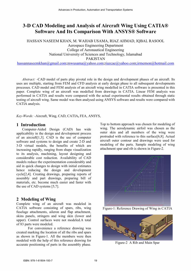
Top to bottom approach was chosen for modeling of
wing. The aerodynamic airfoil was chosen as the
outer skin and all members of the wing were
protruded with reference to this surface[6,8]. Actual
aircraft outer contour and drawings were used for
modeling of the parts. Sample modeling of wing
attachment spar and rib is shown in Figure-2.
Figure-1: Reference Drawing of Wing in CATIA
Figure-2 A Rib and Main Spar
Advances in Production, Automation and Transportation Systems
ISBN: 978-1-61804-193-7 19

All the individually modeled parts were
assembled as shown in Figure-3 and 4.
Figure-3. Assembly of Wing Parts
Figure-4. Complete Skinned Model of the Wing
3 Fem Analysis Finite Element Analysis is a computer simulation
technique used in engineeringanalysis that uses a
numerical technique called the Finite Element
Method[6,8]. FEM is a numerical method which
gives an approximate solution to a problem. It is
done by dividing the problem domain into several
elements. FEM analysis tells us whether a design
will fail under given conditions or not before the
actual physical product is ever really made.
FEM analysis was done by using FEM solver of
CATIA® and ANSYS
® software for individual
components. The results were compared with the
experimental results. Initially single parts were
compared using different load conditions. After the
results had been verified, the parts were assembled
in the assembly workbench and detail analysis was
performed on the complete wing assembly.
4 Element Selection The choice of element type was either to use
Hexagon or Tetrahedron element type. Since the
analysis was carried out in the elastic range of the
materials; therefore, only two element type
used:-
a) Linear tetrahedron (4-node)
b) Parabolic tetrahedron (10-node)
All the individually modeled parts were
3 and 4.
Assembly of Wing Parts
4. Complete Skinned Model of the Wing
Finite Element Analysis is a computer simulation
technique used in engineeringanalysis that uses a
numerical technique called the Finite Element
numerical method which
gives an approximate solution to a problem. It is
done by dividing the problem domain into several
elements. FEM analysis tells us whether a design
will fail under given conditions or not before the
eally made.
FEM analysis was done by using FEM solver of
software for individual
components. The results were compared with the
experimental results. Initially single parts were
compared using different load conditions. After the
had been verified, the parts were assembled
in the assembly workbench and detail analysis was
performed on the complete wing assembly.
The choice of element type was either to use
Hexagon or Tetrahedron element type. Since the
analysis was carried out in the elastic range of the
therefore, only two element types were
node)
5 Mesh OptimizationMesh optimization of the rib was done in order to
reduce the mesh size and to optimize the
results[9,10]. Mesh optimization gra
types of elements are shown in Figure
seen that considerably less number of elements are
required for optimization in case of
tetrahedron elements as compared to the linear
tetrahedron elements.
Figure-5: Mesh Optimization ofa
6 Comparison of Analysis SolutionsIn order to verify and check the results of CATIA
analysis different analysis cases were run. This was
necessary so that it was verified that the correct
boundary conditions were specified. For this
purpose, analysis of single part was done initially.
The analysis was done in CATIA
software. The results from both software
compared with theoretical results as well. An
analysed case is presented below.
6.1 Analysis on a Rib A modelled rib was analysed
CATIA®. Comparison of results was then carried
out. Cleaning was not required after importing of
model to ANSYS® as actual model was already
simplified by removing all the small curves and
fillets. Model was imported as *.model(V4) in
ANSYS®. An arbitrary but same load was applied.
Resulting stress contours are compared in F
and stress concentration is shown in Figure 7.
CATIA®
Figure-6: Comparison of stress contours results
Mesh Optimization Mesh optimization of the rib was done in order to
reduce the mesh size and to optimize the
results[9,10]. Mesh optimization graphs for both
shown in Figure-5. It can be
considerably less number of elements are
required for optimization in case of parabolic
nts as compared to the linear
5: Mesh Optimization ofa Rib
f Analysis Solutions In order to verify and check the results of CATIA
®
analysis different analysis cases were run. This was
necessary so that it was verified that the correct
boundary conditions were specified. For this
purpose, analysis of single part was done initially.
The analysis was done in CATIA® andANSYS
®
he results from both softwares were
compared with theoretical results as well. An
case is presented below.
analysed both in ANSYS® and
. Comparison of results was then carried
equired after importing of
model to ANSYS® as actual model was already
simplified by removing all the small curves and
fillets. Model was imported as *.model(V4) in
. An arbitrary but same load was applied.
Resulting stress contours are compared in Figure 6,
and stress concentration is shown in Figure 7.
ANSYS®
6: Comparison of stress contours results
Advances in Production, Automation and Transportation Systems
ISBN: 978-1-61804-193-7 20

Figure-7: Enlarged image of max stress (CATIA
The maximum stress areas and the values came
out to be very close and comparable.
element type, linear tetrahedron and parabolic
tetrahedron were also compared, both in CATIA
and ANSYS®. It was found that parabolic
tetrahedron was more accurate and converged much
more quickly.
6.2 Analysis on a Complete WingAfter the CATIA
®FEM solver had been verified for
its accuracy and linear analysis, FEM analysis of
complete wing assembly was carried out. The wing
was imported to the analysis workbench of CATIA
and different element sizes were given to each
component depending on its size. Due to higher
computational power required for parabolic element
type critical members were identified and giv
parabolic element type whereas rest were given
linear element types[6,8]. Loads from actual static
test load data were applied on the wing assembly.
Optimized mesh of the de-skinned wing is shown in
Figure 8 and its mesh optimization curve is shown
in Figure 9.
Figure-8: Optimized meshed model of the wing
Figure-9: Mesh optimization curve
7: Enlarged image of max stress (CATIA®)
The maximum stress areas and the values came
out to be very close and comparable. Two different
element type, linear tetrahedron and parabolic
tetrahedron were also compared, both in CATIA®
. It was found that parabolic
tetrahedron was more accurate and converged much
Analysis on a Complete Wing solver had been verified for
its accuracy and linear analysis, FEM analysis of
complete wing assembly was carried out. The wing
to the analysis workbench of CATIA®
and different element sizes were given to each
its size. Due to higher
computational power required for parabolic element
type critical members were identified and given
as rest were given
linear element types[6,8]. Loads from actual static
e wing assembly.
skinned wing is shown in
Figure 8 and its mesh optimization curve is shown
8: Optimized meshed model of the wing
9: Mesh optimization curve
Maximum stress areas were identified and
mesh was refined locally till stress values
converged. Meshes were joined together using
“General Analysis Connection” in CATIA
connections menu and rigid connection property
was given to them. The wing was constrained in all
DOF from the wing fuselag
Analysis was also carried out for a 2D model of
the same wing in ANSYS
boundary conditions were applied to the model.
Results were comparable in both software with an
error of 3.88%. Stress contour is shown in Figure
10. Maximum stress came out to be on the wing
fuselage attachment of the main spar for the selected
load case shown in Figure 11.
Figure-10: Stress contour of the wing
Figure-11: Enlarged image of maximum stress
concentration area
4 Conclusion CAD modeling of the complete wing of a fighter
aircraft was done in CATIA
analysis. The model was also analyzed in ANSYS
software for comparison of results. The results from
both the software were also compared with actual
experimental static testing results with an error of
5%. With same computing time the results were
reasonably close in both the software. For complex
geometries, a small deviati
observed due to the simplifications done for the
ANSYS model. Although, CATIA
FEM software; however, the results were
Maximum stress areas were identified and the
mesh was refined locally till stress values
converged. Meshes were joined together using
“General Analysis Connection” in CATIA®
connections menu and rigid connection property
was given to them. The wing was constrained in all
DOF from the wing fuselage attachment.
Analysis was also carried out for a 2D model of
the same wing in ANSYS® software. Similar
boundary conditions were applied to the model.
Results were comparable in both software with an
error of 3.88%. Stress contour is shown in Figure
aximum stress came out to be on the wing
fuselage attachment of the main spar for the selected
load case shown in Figure 11.
10: Stress contour of the wing
11: Enlarged image of maximum stress
concentration area
modeling of the complete wing of a fighter
aircraft was done in CATIA® along with FEM
analysis. The model was also analyzed in ANSYS®
of results. The results from
both the software were also compared with actual
experimental static testing results with an error of
5%. With same computing time the results were
reasonably close in both the software. For complex
geometries, a small deviation of results was
observed due to the simplifications done for the
ANSYS model. Although, CATIA® is not a pure
however, the results were
Advances in Production, Automation and Transportation Systems
ISBN: 978-1-61804-193-7 21

comparable with ANSYS® software for linear
analysis. The distinct advantages of modeling in
CATIA® were found to be accuracy of model,
parametric modeling, Linear FEM analysis, ease of
machining, and generation of a layout model. CAD
model in CATIA® allowed rapid changing of design
during the design stage and its preliminary linear
analysis, saving both time and reducing costs
considerably.
References:
[1] Brunetti G., Golob B., Computer Aided Design,
2000, 32(14), 877-887
[2] Andreas Krumbein, eN transition prediction for
3D wing configurations using database
methods, and a local, linear stability code,
Elsevier; Aerospace Science and Technology
12 (2008) 592–598 (J)
[3] HuiHua, et al An experimental investigation on
the aerodynamic performances of flexible
membrane wings in flapping flight Elsevier;
Aerospace Science and Technology 14 (2010)
575–586 (J)
[4] X. William Xu, Tony Liu: A web-enabled PDM
system in a collaborative design environment,
Robotics and Computer Integrated
Manufacturing, 19 (2003) 315–328
[5] Riaz Ahmad, Yuqing Fan, Lu Hu, Analying
Innovation, knowledge management and PLM
connections, Proceedings of 6th intconf CAID
& CD, 2005,Delft, Netherlands; P642-647.
[6] Huang, G.Q.; Lee, S.W.; Mak, K.L., Int.
Journal of Advanced Manufacturing
Technology, 2001,18(8), 605-613
[7] FarhadAmeri, and DebaDutta, Product
Lifecycle Management: Closing the Knowledge
Loops, Computer-Aided Design and
Applications, Vol. 2, No. 5, 2005, pp 577-590.
[8] Michael Chun and Yung Niu, Airframe stress
analysis and sizing, Book, 2nd Edition, 1997,
HongKongconmilit press
[9] Vsevolod I. Feodosiev, Advanced stress and
stablility analysis, Feb, 2005, Springer-Verlag
(Book)
[10] Hakim S. Sultan Aljibori, Finite Element
Analysis of Sheet Metal Forming Process,
European Journal of Scientific Research, Vol.33
No.1 (2009), pp.57-69
Advances in Production, Automation and Transportation Systems
ISBN: 978-1-61804-193-7 22