3-d finite element analysis of long- fiber reinforced ... · pdf filematerial properties, for...
TRANSCRIPT

Thisartiicle wasoriginally presented
at the 2000 ASMEDesign Engineering
TechnicalConferences, heldin IBalt1imore, MO,
in September 2000.Repr,inted with
permission ..
noise and high impact resi lance, but. they areinferior to steel gears in their load capacitie . For
thi reason, there are few example of plasticgears being used for power transmission. If plasticgears reinforced with high-strength fibers, such as
glass or carbon fibers. 3J"e realized, they willbecome useful plastic gears of high strength, as
well a having the above-mentioned properties.Although it is relatively easy to manufacture
composite gears reinforced with chopped or par-ticulate fibers by using the method used for
isotropic gears, manufacturing iii composite gearfilled with long fibers is technically difficult.There are studies both all composite gears manu-factured from chopped- or particulate-fiber rein-forced materials (Refs. 11 and 9), and all long-fiber reinforced composite gears (Ref. 8). Almo tno attempt hall 'been made 10 investigate the possi-ble stress and deformation variations for gears thatcould have been made of an orthotropic material.
In thi study, composite spur gears, ill whichlong fibers are arranged along tooth profiles, areanalyzed in 3-D by u ing the finite element analy-sis method (Ref. 2). This type of composite spurgear was manufactured by Shiratori et al. (Ref. 8).A casting method was adopted to manufacture thegears. As shown ill Figure I, for such a structure,the gear is composed of two regions. which are the
long-fiber reinforced and the chopped-fiber rein-forced regions. It is important to note that there isalmost no approach to analyze this type of com-posite gear because of different fiber orientationsat different sections of the long-fiber reinforcedregion of the tooth.
Since elements have different orientations andmaterial properties, for the finite element analysisof this type of composite gear with complexgeometries, material propertie of each elementconstituting the mesh should be defined separate-ly. Forming the model geometry, ubdividiag itinto elements, finding the appropriate mesh densi-ty and preparing the input data for II finite element
3-D Finite Element Analysis ofLong- Fiber ReinforcedComposite Spur Gears
~agda§ Alagoz •.M.A. Sah,ir Arikan. O. Gunduz Hilir and Levend Parnas
12 MARCH/APRIL 2002· GEAR TECHNOLOGY' www.gearrechnology.com' www.poweflransmisslon.com
This article describes a method and a comput-er program that were developed for 3-D finite ele-ment analysis of long-fiber reinforced compositespur gears, in which long fibers are arranged
along tooth profiles. For such a structure. the gearis composed of two regions; namely the long-fiber reinforced and the Chopped-fiber reinforcedregions.
IntroductionCompared with monolithic materials, compos-
ites have unique advantages, such as highstrength, high stiffnes ,long fatigue life. low den-sity, and adaptability to the function of the struc-ture. Additional improvements can be realized inthe corrosion resistance, wear resistance, appear-ance, temperature-dependent behavior, thermalstability, thermal insulation, thermal conductivityand acoustic insulation.
Plastic gears have excellent properties, such asself-lubrication, high chemical resistance. I.ow
Chnpped·fiberrei nforced raqions
Figur.e 1· Long-fiber reinforced tooth.
Figure 2-Gear models that CGII be generated by.tlJe developed program.

program becomesa complex. and time-consumingtask, which is impossible to perform manually. All
of the above-mentioned tasks are performed by the
pre-processing module of the developed program,Main inputs for this module of lhe program aremformaaon on basic gear geometry, gear drivedata, materia! properties and long-fiber reinforce-
ment geometry. Finite element. rneshe are auto-
matically generated. and mesh information withother required data is written to a file in the input-file formal of ABAQUS . Stresses are read fromthe output me of ABAQ S® by the po t-process-
ing module. and color-coded drawings for various
stresses and failure indexes are displayed. For thelong-fiber reinforced region, failure indexes are
calculated by using the tensor poly-nomial failurecriterion used by Herakovich (Ref. 5).
Finite Element ModelingFinite element modeling mainly consists of
gear model selection. mesh generation. boundarycondition input, material definition and load def-irtition, The first step is the selection of the gear
model among the ones given in Figure 2. Next.the tooth profile is divided into segments. and themesh is automatically generated for long-fiber
reinforced and chopped-fiber reinforced regions.
irsI, a 2-D mesh is generated. Then, the 3-D'me h i fanned by con ideringthe face width ofthe gear and the number of divisions specified in
Lhis direction. During mesh generation. thickness-es and locations of fiber arrangements and meshdensity can be eontrolled. Then, boundary condi-
tion . material definition and load definition areentered, Finally, me h information and otherrequired data are written to a file in the input-fileformat of ABAQ S®.
Gear Models. In the literature. various modelsare used for finite element analysi of gears.These include single-tooth models, models with
one full tooth and two partial Leeth at both sides.models with one full tooth and the tooth spaces
on both sides, and three-tooth models. The most.
. unable model i. determined by comparing the
Ires e found by using different models. Sinceall the model were developed and u ed forisotropic materials. the arne compari ons shouldbe made for compo lte materials. The program bythe authors is capable of generating meshes byu ing the gear models given in lgure 2.
Generatio» of the Outside Profile for theModel. As shown in Figure 3. the out ide profileof the model is generated by using seven guide
point. Point I is 0[1 'the tooth cearerline: point 2is at the tooth tip ..The segment between points 2
and 3 is the involute tooth profile: the segment
Figure 3-Gllide poirlts on the outside profile.
Baziar polvgon pomt 1
Cagda, Allago!worked (}J! this subject {IS
parI of his IIUI.ller 0/ science
program at Middle £aSI
Technical University. locat-ed ill. Ankara .. Turkrv.
Berier curve point
Dr. M.A. Sahir .Arikanis a professor in Ille depart-ment of medlllllica/ engi.fleering at Middle EastTechnical University. Hisareas ofinterest includeCAD/CAM. robotics.machine elements. machinedesign; gear design andgear dynamics.
Dr. IOmer Gundiiz BiIi,i,s a professor ill tire depart-ment of mechanical engi-fleering at Middle EastTechnical University Hisareas of interest ill dudeexperimental SIre ss analysis,fracture mechanics andcomposite materials.
Dr. Levend Parn8!Sis em associate prole SOT
and assistant chairperson ofthe department of mechani-cal engineering 01 MiddleEast Technical University:His areas of interest includecomposite tructures. com-putational allalysis of struc-tures, fracture mechan irs.experimental mechanics andbiomechan ics.
www,powerlransmisslon.com • www,gearlechnology.com • GEAR TECHNOLOGY'· MARCH/APRIL .2002 13
Figllre4-Upper .bOlmdary of tile IOllg-fiber rel'n·forced· region formed by using a bezier c/jrve.
Points on bezier curve -..JF:::::::W"- Bezler pDlygon poi~ts
..J~~~.'" Ttueknasslines normal lathebaner curve
Figure 5-Genemled mesh for the upper sectio» ofthe 101Jg-jib.errehlforced region
bounded by points 3 and 4 is the trochoid tooth
fillet profile, Point 5 is on tooth space centerline.
The rim thickness of the gear is the di tancebetween points 5 and 6. Finally, point 7 is again
on the tooth centerline. Calculations on geargeometry and tooth profiles are made using themethods and equations of Arikan (Refs, 3-4).
Mesl, Generatia« fort/Ie Long-FiberReillfor;ced Regim.l. In the long-fiber reinforced
region, fibers axe in erred into the tooth along thetooth profile. Bezier curves are used to term thegeometry of the fibers, The shape of a Beziercurve can be controlled by making use of a defin-ing polygon. As hown in Figure 4, four pointsare sufficient to form the polygon and the Beziercurve.
During mesh generation, lilies normal to theBczier curve and passing through the Bezierpoints are drawn. Line lengths are made equal to
the fiber thickness. Interior nodes are obtained bydividing the lines into segments. a shown inFigure 5.
As seen in Figure 5, above the leaving point.fibers are nol parallel to the tooth profile, but
have a curved shape determined by the Beziercurve geometry. Below the leaving point, fibersbecome parallel to the tooth profile. Interior
node below the leaving point can be generatedby moving into the tooth in a direction normal to
Intersection of involute andtrochoid
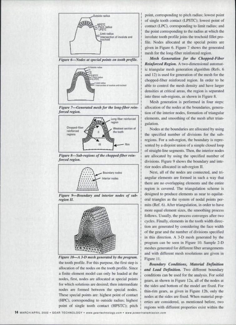
Figure 6--Node5: at special points on tooll. profile.
- I Intersecucn 1:11~nYoluta.md tr~cho]d
Figure 7 Generated mesh for tile 10ng.Jiber .rei"-forced region:
Long-fibe r reinforced
Chopped-fiberreinforcedregions
We axe st section ofthe tooth
Figure ,8-Sub'regiolJs of the c"opped~fiber rein-forced region.
IMenor nod as
Figure 9-Boulidary and interior nodes of sub·region II.
Figure 10-A j·D' mesh genemled by the program.
the tooth profile. For this purpose, the first step isallocation of the nodes on the tooth profile, Sincea finite element model can only be loaded at thenodes, first, nodes are allocated at special. pointsfor which elations are desired; then intermediatenodes are formed between the special nodes,These special points arehighest point of contact(HPC), corresponding to outside radius; highestpoint of single tooth contact (HPSTC); pitch
point. corresponding to pitch radius; lowest pointof single tooth contact (LPSTC); lowest point ofcontact (LPC), corresponding to limit radius; andthe po.int corresponding to the radius at.which theinvolute tooth profile joins the trochoid fiUet pro-file, Nodes allocated at the special points aregiven in Figure 6, Figure 7 shows the generatedmesh for the long-fiber reinforced region,
Mesh Generation for a,e CI,opped·FiberRe.inforced Region. A two-dimensional automat-ic triangular mesh generation algorithm (Refs. 6and (2) is used for generation of the mesh for thechopped-fiber reinforced region. In order to. beable to control the mesh density and have largerden itie at critical areas, the region is separatedinto three sub-regions, as shown in Figure 8.
Mesh generation is performed in four steps:allocation of the nodes at the boundaries. genera-tion of the interior nodes. formation of triangularelements. and smoothing of the mesh after trian-gulation,
Nodes at the boundaries are allocated by usingthe specified number of divisions for the sub-regions, For a sub-region, the boundary is repre-sented by a disjoint union of a simple closed loopof. traight-Iine segments, Then. the interior nodesare allocated by using the specified number ofdivisions, Figure 9 shows the boundary and inte-rior nodes allocated in ub-region IL
Next, all of the nodes are connected, and tri-angular elements are formed in such a way thatthere are no overlapping element and the entireregion is covered. The triangulation scheme isde igned to produce elements as near to equilat-eral triangles as the sy tern of nodal points per-mits (Ref. 6), After triangulation, in order to havemore equal. element izes, the moothing processfollows, Usually. the process converges after twocycles. Finally, elements in the tooth width direc-tion are generated by considering the face widthof the gear and Ihe number of divisions specifiedin this direction. A 3·D mesh generated by theprogram can be seen in Figure 10. Sample 2-Dmeshes generated for different fiber arrangementsand with different mesh resolutions are given inFigure 11,
Boundary COlJditiOIlS,.Material Dejinitiontuzd Load Dejillition. Two different boundaryconditions can be used for the analysis. or solidgears. as shown in Figure 12a. all of the nodes atthe ides and bottom of the model are fixed, Forthin-rim gears, as given in Figure 12b. only thenode at the sides are fixed, When material prop-erties are considered, as mentioned before, tworegions with different properties exist within the
1:4 MARCH/APRil 2002' GEAR TECHNOLOGY' www.geartechnoJogy.com .• www_powerlransmission.com

gear. These regions are the long-fiber reinforcedregion, in which unidirectional fibers are present,and the chopped-fiber reinforced region, in whichthere are randomly oriented. discontinuous fibers.If the fiber orientation ill a composite material istruly random in a three-dimensional sense, thecomposite exhibits three-dimensional isotropy.Therefof~, the material forming the chopped-fiberreinforced region can be considered as a materialwith a single elastic modulus and Poisson's ratio.In the long-fiber reinforced region, as shown inFigure 13, each element is a unidirectional, fiber-reinforced composite and has different materialproperties with respect to the global coordinatesystem because of its orientation. On the otherhand, elements have the same elastic properties inthe local coordinate system given in Figure 14.The local coordinate system is obtained by rotat-ingthe global coordinate system about axis 3 bythe required angle. As seen in Figure 15, all of theelements in a slice have the same orientation andconsequently the same elastic properties withrespect to the global coordinate system. Thus, all Figure .12-Boulldary conditiollS.
Figure l1--Sample 2-D meshes gener.ated by the program.
b.
Figure 13-Fiber reinforcement in the .lollg·fiberreinforced region.
Figure 14--Material directions in the long-fiberreinforced region.
elements in a slice can be reduced to an elementset. Elastic properties of element sets are definedin their local coordinate systems.
For loading, distributed loads in the toothwidth direction are resolved as shown in Figure16. Thus, a uniform displacement distribution isobtained in the face-width direction (Ref. 3).Loads are applied to the nodes i~na direction nor-mal to the tooth profile,
Pest-Processing of ResultsFor fallure analysis, stresses are read from the
output file of ABAQUS®, and color-coded draw-ings for various stresses and failure indexes aredisplayed. Figure 17 shows a sample outputscreen for failure index, Numerical values of thestresses and the failure index for an element canbe displayed by bringing the cursor on the elementand clicking the mouse button. In the figure. theblack-colored element is the one for which thenumerical results are displayed. At this step, it isalso possible to replace the previously input mate-rial properties with new ones, and see new failureindex values.
A tensor polynomial failure criterion (Ref. 5) isused to calculate the failure index for the long-fiber reinforced region. According to this criteri-on, failure occurs when,f (O'jj) = FLO]+ F102 + FJoJ
+ FIIO'~+ F220i+ F3P;+ F""o;+ FssO';+ F66O'g
+ 2 F'2(J,(J2 + 2 PL30"0'3 + 2 F230'2(J3 ~ I (1)
iii i 1
~Global coordinates
3
Figure lS-.4Jl element set formed by a slice.
Figure .16-Resoluti01I of distributed loads.www.pawerfransmission.com • www.geartechnology.com • GEAR TECHNOLOGY. MARCH/APRil 2002 15

where.
F _I + .l .. FII = -I (2)F·.•II_llndft 1- x,. Xc' XTXc
3.0453.971 _ 1 . 1 . -1I 5.413 F2-y+--y-. Fn ::
YTYc(3)
11.194 T C'12.19
,2Ui54832 F - I + 1 . F33= -1 (4)194.9 J - z,. Zc' ZrZ c
1 1 I (5)F44=Q2 F55=~ F66::~
Figure 17 Sample output screen.
41.2
'" 41~~ 4O.B....~ 40.6
'".s 40.4'",,:.,.... 40.2:
796'8 1,~~598"1
389"5 ~~....
310-4
40a w.ooo 12.0002,ooa 4.000 6,000 8.000
Number oleiements = Number 01elements in 2"0"Number ofalernants in the face width direction,~----~~--~--~----------------------------------"----~~--------~Figure 18-Results of convergence tests.
Table l-Isotropic Spur Gear Data.IBasic Gear Ceamell'{Pressure, AngleModule. mAddendumDedendumGenerating Tool Tooth lip Fillet Hadius
20°4.5,mmUHOOxm1.25Oxm'O.3oo.x m
,GearNumber of TeethFace WidthRim Thickness
726.25 mm2 x m
MaterialEra stic Mod ulusPoisson's Ratio
210 GPa0.3
LoadingLoad at Tooth Tip 500 N
Table 2-Bending Stresses at Tooth Root.
Tooth Model Maxjmum Bending Stress IMPa)'Ie nsile Campres.sive
4'0.9 - 48.2Single ToothSingle Tooth with Tooth SpaceThree Teeth
39.739.8
-47.3-47.9
SourceDeveloped ProgramAGMA EquationsOdaer al. (FEMlOda,el at (Experimental)
Ma.ximum IIlending Stress (MPal6.1716.2126.2906,236
In the above eqaations, x,.. Xc' Yr' Yc. z,. andZc indicate tensile and compressive strengths in
X, Y and Z directions; and Q, Rand S indicate
shear strengths in XY, XZ and YZ planes. re pee-tively, Tsai and Hahn (Ref. 10) have proposed the
following equations for interaction coefficients
F12• F'3 and F23,
(F . F ) 112FI2 =-
- II 22 (6)2
Fn =-(F)) F33) l12
(7)2
(F F ) 112F23 =- 22 33 (8)
2
Failure index is defined as the inverse of f(Gij)
given in Equation 1. Thus, a failure index less
than one indicates failure, and a large failure
index means a large margin of safety.
Verification or the ModelThe model is verified by specifying all of the
elements of the mesh as isotropic elements and
comparing the results with previous results givenfor isotropic materials. Before the solution, con-vergence tests are performed, and a proper toothmodel is determined. The spur gear with proper-ties given in Table I is used for the tests. For theelution, all of the nodes at the sides and bottom
of the model are fixed. Results of the covergencetests are given in Figure 18. By making lise of the
figure, it is decided to lise about 6,000 elements
1800 elements in 2-D and 8 divisions in the facewidth direction),
Bending stresses at the tooth root found byusing different tooth moclels are given in Table 2.
By making use of the table. it is decided to use thesingle-tooth model for the stress analysis, since
more complex models give sires es that are onlya few percent different than the ones given by thesingle-loath model.
After deciding on the tooth model and thenumber of element. tooth root stresses found for
16 MARCH/APRIL 2002 .' GEAR TECHNOLOGY' www.geartechno(ogy.com· www.powertransmisslon.com

isotropic gears by using the model are comparedto the results found by u_ing AGMA equation(Ref. I) and re ult given by Oda et al, (Ref. 7).
Stresses given in Table 3 are again for the gearwhose properties are shown in Table I. In order ILo
be able 10 compare the tree e wi1h the re ult
given by Oda et al, (Ref. 7). instead of 500 N. n
tip load of I kg,lmm is applied 10 the tooth. It isfound that stresses calculated using the model an:
in good agreement with other results.ampleRe ults
Sample re ult~ are obtained for the compositepur gear whose properties are given in Table 4.
In the long-fiber reinforced and chopped-fiber
reinforced regions, glass/epoxy is used. Materialproperties of the long-fiber reinforced, unidirec-
tional composite material are hown in Table 5.and material properties of the chopped-fiber rein-forced composite are . hown in Table 6 (Ref 8).
As shown in Figure 19. from a failure point ofview. there are three critical ecuon: in a com-
posite gear tOOlh. In s ction I. the critical stresscomponent is the axia] tensile srresi in the direc-lion parallel 10 Ihe fibers. During a failure in Lhiseciion, fibers are broken. In ection 2 nd 3.lhe
critical sire. s component is the transverse tensile
stressin tile directi n normal to the fibers. Duringfailures in these sections. fiber separation isobserved. Arrows at the ends of [he lines markingthe critical' ecuons indicatethe failure direction.
Re ults obtained by using the developed pro-gram fOT glass/epoxy and carbon/epoxy gears,together with the resuhs given by Shiral.ori. c\ al,(Ref. 8) are shown in Figures 20 and 2 L respec-
lively. For failure analy. i. of isotropic materials,the maximum !;tres~ should be considered; forunidirectional materials. tile sires, along tile fiberdirection should be considered. Thu , for thechopped-fiber reinforced region (in ide of the
looth).lhe ratio of the stress (in the direction par-allel wuh the tooth centerline) to the strength is
calculated at the critical (weakest) section of Ihe
tooth, or the long-fiber relnforced region (theregion next 10 the outside surface of the tooth).the ratio of Ihe stress along the fiber direction tothe trength in the same direction i. calculated. As. een in the figures. re ults of [he program agree
well wuh the results gi en by Shiratori, et a1.(Ref. 8).
EITecl of reinforcing thickne s of the long-
fiber reinforced region and the in enion depth ofthe fiber on trength, of glass/epox)! gears are. hown in - igures 22 and 23. respectively. During
iruerpreunion of the results, failure is always
observed in secticn 2, where the critical stress
Caribon/EpOlll'JU'5.631.7
0.060.'0310.3:.28932611.1033431.6
CllribOn/EJlOXY17
10.330.2.4811698
37.6
T!iIJ!e 4-Composite Spllr 'Gear !latil.
I kg,/mm
-- -----
Table 5-Millerial Properties for the long-Fiber Reinlorced Reglion(Unidirectional Composite).
-- - ---
Table 6-Material Proporties for tho ChoPllcd-fiber Reinforced RoglOn(Isotropic Composite).
---------
......"'.po ......rl'.n.mlnlon.com • "' .......IIU" ... chnoIOIlY com· GEAR TECHNOLOGY' MARCH/APRIL 2002 1J
B sLeG.earGeometJryPressure AngleModule,mAddendumDedenoumGenerating Tool Tooth Tip Fillet Radius
Ge-rNumber of TeethFace WidthRim Thickness
306.25 mm2xm
20~Smm1.0lXllI m1.250 x m0.300 x m
MaterialElastic Modulus,Poisson's Ratio
210 GPa0.3
LoadingLoading at Tooth Tip
GPaClPaGPa
Gll!llS/EpOXY15.26.531.710.130.08,0.310326128.258841.4
AKial Modulus. EITransverse Modulus, E2Shear Modulus, G'2Poisson's Ratio, u12Poisson's Batio, \)23Fiber Volume Ratio, VfAxial Tensile Stren!lthAxial Compressive Stren!lthTransverse Tensile,StrengthTransverse Compres.sive StrengthTransverse Shear Strength
IMPaIMPaMPaMPaMPa
GPaGlasslEplIXY
9.20.3110236111698
41.4
Elastic Modulus, EIPoisson's Ratio. 1JllFiber Volume Ratio, VITensile StrengthCompressive StrengthShear Stren!lthTransverse Shear Strength
IMP.IMPIMPaMP.
component i_ the transverse tensile stress in medirection normal to the fibers. As seen in Figure22. the failure index (and tile strength) increaseswith increasing reinforcing thickness until thethickness becomes 1.5 mm, Beyond 1.5 rnm,reinforcing thickness has no positive ef~cci on
gear strength.Figure 22 . haws the effect 01 insertion depth
(hr) of the fiber on gear strength, Increased inser-lion depth ha a mall positive effect 011 gearstrength,
In order to see the effect of different materi-als ami different fiber volume rutios for long-fiber

-- Developed program-e- Shiratori, at al.
0.08
0.06
0.04
0.02
-0.02
-OJI4
Chopped·fiber regionlong·fiber
!..regiDn,..,.j
reinforced and chopped-fiber reinforced regionson gear strength. siress analyses are made for s-glas lepoxy, cerbon/epoxy, kevlar/epoxy andboron/epoxy gears. For chopped-fiber reinforcedregion, fiber volume ratios (V cf) of 0.1. 0.3, 0.5and 0.7 are used; for the Iong-fiber reinforcedregion, fiber volume ratios (Vir) of 0.1. 0.3 and0.5 are used. The same fiber and matrix materi-al.s are 1I ed fer long-fiber reinforced andchopped-fiber reinforced regions.
Material properties for the fibers and thematrix are given in Tables 7 and 8. re pectivejy,As a measure of the strength, calculated mini-mum failure index values together with the criti-cal sections at which they are ob served are givenfor s-glass/epoxy, carbon/epoxy. kevlar/epoxyand boron/epoxy gears in Tables 9-12.
Fiber volume ratio combinations. whichresult in the weakest and the trongest gears, areshown in Tables nand 14. respecti ely. A - ellin the table, for different materials. differentfiber volume ratios should be used in order toobtain the strengestpossible gear.
Discussion and. ConclusionA method and a computer program have been
developed for 3-D finite element 3_nalysis of long-fiber reinforced composite pill" gears, in whichlong fibers are arranged along tooth profiles. Thedeveloped program is verified by performingstress analysis all isotropic gears .. Result s of theprogram are compared to the results given forcomposite gears by Shiratorket al. (Ref. 8), andgood agreement is ob erved, Although the pro-gram is capable of using three iliff erent 'tooth mod-els---,namely single tooth, one full tooth wilh toothspaces at both side and three-tooth modeJs-it isfound that re ults gsven by the ingle-tooth modelare atisfactory for tress analysi purpose ..
For glass/epoxy gears, effects of reinforcingihicknes of the long-fiber reinforced region and.insertion depth of the fibers on gear strength areinvestigated. It is found that strength increaseswith increasing reinforcing thickness until a crit-ical thickness is reached. Beyond '[he criticalthickness, reinforcing thickness has no positiveeffect on gear trengrh, On the other hand,increa edin ertion depth has a small positiveeffect on gear strength.
Finally. In order to see the effects of differentmaterials and different fiber volume ratios forlong-fiber reinforced and chopped-fiber reinforcedregions on gear trength, sires analy es are madefor -glass/epoxy, earbonzepoxy.kevlacepoxy andboron/epoxy gears. II. is found that the reinforce-ment with kcvlar/epoxy and carbon/epoxy is effec-
18 MARCH/APRIL 2002 • GEAR TECHNOLOGY. www.gllllrrBchIlDJolIl'.com" www.powe,lrs·nsmJss;(I'n.com
Distanc e on critical plane
Long·fiberI region:
Figure 20--Stl'ess Ratiol:for Glass/Epoxy Gear.
1--·----
-- Developed program-e-- ShiraIori. at al.
.0.04
0.01
-0.02
-<l.D4
Chopped'-'fiber regionLong·fiber
I..region I--lilt
Distance on critical secUonLong-fiberI region:
Table 1-Material Pmperties for the Fibers.S·GJass Clllfbon IKevlar BQ~on
Longitudinal ElastiC Modulus MPa 85,600 235,000 135,000 385,000Transverse Elastic Modulus MPa 85,600 16,550 .5,200 385,0001longitudinal' Shear Modulus MPa '5,110 14,400 2,890 166,5001longitudinal Poisson's Ratio 0.22 0.2 0.35 0.21Tensile Strength MPa 4,200 2.599 3,445 .3,900Compressive Strength MPa 520 2,500 551 4,550Shear Strength MPa 350 400 275 700
Table S-Maledal Propel1ies for the Matrix (EpoxV)., Elastic Modulus MPa' 4,200
Shear Modulus MPa 1,340Poisson's Ratio 0.38Tensile Strength MPa 52Compressive Streng,th MPa 130Shear Strength MPa 85

Ii• Request more information i
• Contact the author or companies mentioned Ii• Make a suggestion I'
Or call 18471437-6604 10 talk to one of our editDrs! I i '-- -1
live in impreving the iooth slrength, wilhkevlartepoxy gears being the strongest. For thegears made of boron/epoxy, the critical section ismainly section 3. where !he critical stress compo-
nent i the trail verse tensile tress,A general trend observedis: Increasing me
fiber volume ratios results in fiber failures ill the
direction normal to the fibers. i.e. fiber separation.
Acknowledgmeor-The author. would like to thank the
CAD/CAMlRobolic Center of Middle astTechnical niversity :for providing computerfacilities. 0
R f' reneesI. AGMA Standard 2001-888. "Fundamental R~lingFactors and alculation Method!> for Involute Spur andHelical GeM Teeth:' 1988.2. Alagol. <;. Finite Element Anak~is af Long FiberRf.'inforced' Composit« Spur Gears, M.Sc. Thesis, 1999.
techanical Engineering Depanrncm, Middle EastTechnical Ul!iver~ily. Ankara. Turkey.3. Arikan, M.A.S. Compl!ll'r Aided Dynamir Modl'flillgof SPill' Gears, Ph.D. Thesis. 19K7. IeehanicalEngineering Department. lIiddle East Technical
niversiry, Ankara, Turkey.
4. Arikan, M.A..S."Delermination of Maximum PossibleContact Ratios for Spur Geur Drives with Small lumberofTeelh." Proceedings of 1995 ASME De!Jign E"gint'f'rillll'Techniral . miful!lIcl.'s. 1995. DE-Vol. 82. pp. 569--570.S. Herakovich. .T. j\'1edu;mics of Fibrous Composite ..Jolm Wiley & SOil'. New York, 1998.6. La. S.H. "A e ...., Mesh Generotion Scheme For Arbi1Foll1'Planar Domains:' tntemationa! JOl1n1(,l/ for NumericalMethods in Engineerillg, I S. Vol. 21. pp. 1403-1426.7. ada. S .. K. agarnura and K. Aoki." Ire s ,a!!aJy~i~ofThin Rim Spur Gears b} Finite lement Method." BullelillojlheJSME. IgSI. Vol. 25. p, 1273.8. Shiratori, E .. et al, "A Study of folding Method unoStatic rrength of arbon Fiber-Reinforced Plastic Gear."Bulil'lit' of Ilrf.' JSME. 1986. Vol. 24, o. 198. pp,2 177-lLfO.9'. Tanaka. S. nd K. Morimol/l. H ccuracy and WearResistance of mall Injeetion- - 10lded Plastic Gears Filledwith Fiber or arbon." JSME lntemanonal Journal. 1991,Vol. 34. No.2. pp, 310-314.10.Tsai, S.W. and H.T. Hahn. introduction 10 'heComposit« iJall.'riols. Technomlc Publi bing Co .•Lanchester; PA. 19&1.II. Tsukomutu, . and K. Teresirna, "Pundamernul
haructeristics of Plastic 'Gem Made of TherrnnplustleRc~in Filled ",i[1I Vruiou~ Fi/)el'!.," JSM£ IntemationalJournal, 1.990. Vol. 33. No.4. pp. 590-5%.12. Yixin, M. and E Mingwu. "Ad" need TwoDimensional Automatic Triangular Mesh Genenniou for
Ten Us What You Think ...Visit. www.glln.chnology.comlo• Rate this article
5
3+-~~-r--~--~~--~~0.8 1.2 1.4 1.61'.8
Fiber thickness [mrnl
f:igllre 22 Effect ofr,einforring thickness on geal' strenglll "glassJe-po~gean
10 -
" 9..8...
.5
~:= 6~
54
0.5.5
------...-.- _ .
0.65 D.BS D.!J5
Figure 23 Effeclof illsertio/l deptli ongear .strengtll (glass/epoxy gear).
!.~~Ie 9-Minimum Failure Indexes and 'i:rilical Sections for S-Glass/Epoxy Gear.
0.54.85, l'4.68 •.13.80,3:
OJ4.95.14.1'9., 13.27.3
0.10.3O.S
3.90,1*4.63,13.!W,2
4.58,114.89,113.99,3
-(Minimum Failure Index: 3.'90. Critical Section: I!
lid0..1 10.3 0.5, D.1
101.1 5.99,1 5.79, ,2 5.85,2 5.93,2lin 10'..3 6,53.1 6.10,2 4.71,2 4.73,2
'0.5 5.97,2 4.63.3 4.55,3 4.47.3
Table l1-Millimum Failure Inde,.!~ and Critical Sections ',or KevlarJiEpoxy Gear.
1]1.'1 0..3 O.!5 01.10.1 5.20,,1 5.99', " 5.98,31 5.83.3:
'VII 0..3 6.31.11 6.26,1 5.99,3: 5.85,310,5, 1.52,11 6.44,3 '6.11.31 16.02.3
lable 12-Minimum faUure Indexes and Crilical Sections for Boron!Epoxy Gear.
'\1.101.1 0.3 01.5 01.1
0.1 5.10,3, 4.90, :I 4.4Q, :I 4.10,3\In D.3 4,32. 3, 3.94, J 3.50,3: 3.94.3,
0.5, J.80,3: 3.61. 3 3.20,3 3.10,3
Table 13-lFiber Volume Ratio Combinations which Result in the Weakest Gears.II(BvIBrJEpDx~
0.10.15.20
11
IBoron/Epox,0.50.73.103
v"V.lFailure IndexCritical Section
S-GI Sl/~PDXY0.50.7
3.273,
Ccaibo.nJEpoxy0.50.7
4.473
Table 14-Fiber Volume Ralio Combillillions which Result in Ihe S~rongesl Gears.S·GlaSS/Epoxy GarbonlEpoxy IKB'lIlIr/Epoxy IBoron/Epox'll
V~ 10.1 0..3 0.5 01.1
Vol 0.7 0.1 0.11 01.3Failure lndex 4.95 16.53 7.52 4.90Crilica'i Section 1 1 3
wwwpo",erlr8,nlmlsslon.com • www.!lurr.ch·noIOljly.com • GEAR TECHNOLOGY' MARCH/APRIL 2002 '19