3-d geometric modeling for the 21st century
TRANSCRIPT

Spring • 1999
3-D Geometric Modeling for the 21st Century
Holly K. Ault Worcester Polytechnic Institute
ABSTRACT There have been numerous and dramatic changes in graphics technologies used in engineering design during the last thirty years. Computer models that represent the geometric characteristics of parts and assemblies are used extensively in design, analysis and manufacturing. This paper briefly describes these new geometric models used in contemporary CAD software, including wireframe, surface, solid and parametric models. Their use in engineering design and analysis is reviewed. The impact of these new technologies on the engineering design graphics curriculum is discussed.
Introduction The use of geometry in engineering dates back to the ancient Egyptians and Babylonians, however, the first formal mathematical structure for geometry was provided by the Greeks, including Thales, Pythagoras, Plato and Euclid in the 4 th and 5th centuries B.C. (Thompson, 1998). Projection theory developed during the Renaissance, and the principles of technical drawing and descriptive geometry were introduced by Gaspard Monge in the 18th century (Bertoline, 1997). Today, children are introduced to basic shapes in grammar school, with more formal study of geometry in the high school curriculum. These courses typically include the study of size, shape, position and other properties of physical objects, deductive (logical) thinking, and an introduction to basic trigonometry (Stanford University, 1998). Common engineering curricula include one or more courses in design graphics, including projection theory and graphics standards for the production of orthographic drawings (Bertoline, 1997).
In the past three decades, the terms geometric modeling, and in particular, solid modeling have been associated with the technology of using computer aided design (CAD)
systems to define the shape and form of geometric structures for the purposes of engineering design. Mortenson (1985) defines geometric modeling as "the technique we use to describe the shape of an object... Geometric modeling provides a description or model that is analytical, mathematical and abstract rather than concrete." Geometric models may be graphical, mathematical or verbal representations of the object.
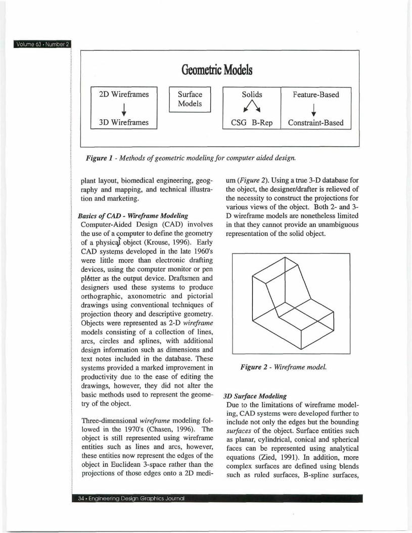
Geometric modeling in CAD applications has evolved through a series of phases in order to improve the geometric representation of physical artifacts, as shown in Figure 1. Wireframe and surface models are not able to fully define real objects, and have been supplanted by more sophisticated solid-based systems for engineering design, however, they are still widely used for documentation. Solid models provide a complete mathematical description of the mass and boundary of an object, and are useful in providing a complete, unambiguous representation of the geometry of any physical object. Thus, solid models are useful for visualization and analysis in engineering design for a multitude of applications including product design, mechanical design, architecture, structural design, electronics, piping and
2D Wireframes
3D Wireframes
Geometric Models
Surface Models
Solids
A CSG B-Rep
Feature-Based
1 Constraint-Based
Figure 1 - Methods of geometric modeling for computer aided design.
plant layout, biomedical engineering, geography and mapping, and technical illustration and marketing.
Basics of CAD - Wireframe Modeling Computer-Aided Design (CAD) involves the use of a computer to define the geometry of a physical object (Krouse, 1996). Early CAD systems developed in the late 1960's were little more than electronic drafting devices, using the computer monitor or pen plotter as the output device. Draftsmen and designers used these systems to produce orthographic, axonometric and pictorial drawings using conventional techniques of projection theory and descriptive geometry. Objects were represented as 2-D wireframe models consisting of a collection of lines, arcs, circles and splines, with additional design information such as dimensions and text notes included in the database. These systems provided a marked improvement in productivity due to the ease of editing the drawings, however, they did not alter the basic methods used to represent the geometry of the object.
Three-dimensional wireframe modeling followed in the 1970s (Chasen, 1996). The object is still represented using wireframe entities such as lines and arcs, however, these entities now represent the edges of the object in Euclidean 3-space rather than the projections of those edges onto a 2D medi-
34 • Engineering Design Graphics Journal
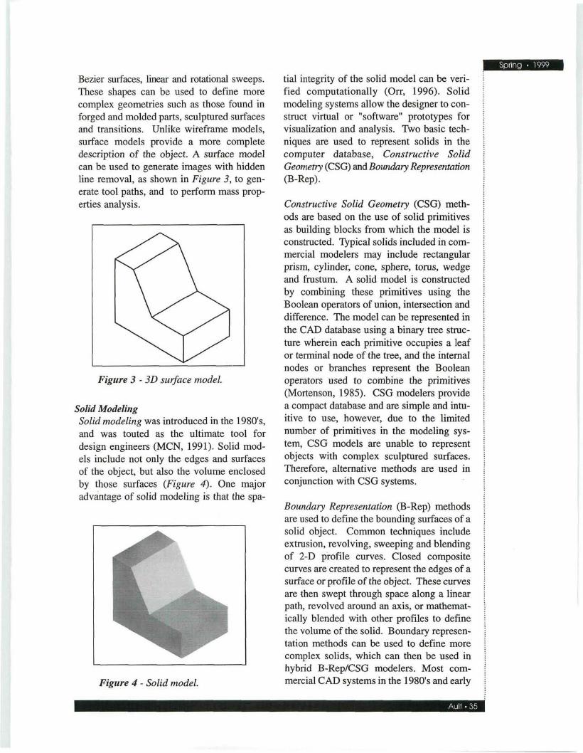
um (Figure 2). Using a true 3-D database for the object, the designer/drafter is relieved of the necessity to construct the projections for various views of the object. Both 2- and 3-D wireframe models are nonetheless limited in that they cannot provide an unambiguous representation of the solid object.
Figure 2 - Wireframe model.
3D Surface Modeling Due to the limitations of wireframe modeling, CAD systems were developed further to include not only the edges but the bounding surfaces of the object. Surface entities such as planar, cylindrical, conical and spherical faces can be represented using analytical equations (Zied, 1991). In addition, more complex surfaces are defined using blends such as ruled surfaces, B-spline surfaces,
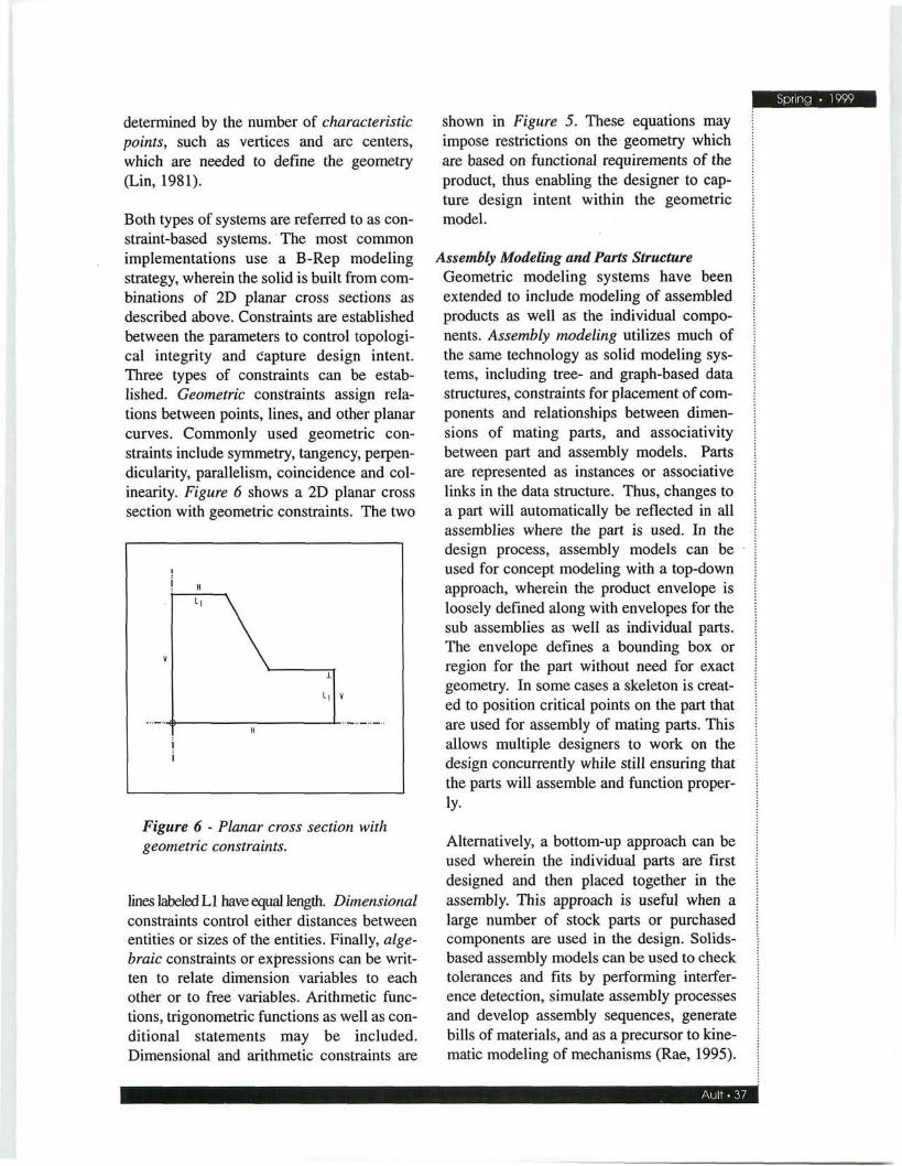
Bezier surfaces, linear and rotational sweeps. These shapes can be used to define more complex geometries such as those found in forged and molded parts, sculptured surfaces and transitions. Unlike wireframe models, surface models provide a more complete description of the object. A surface model can be used to generate images with hidden line removal, as shown in Figure 3, to generate tool paths, and to perform mass properties analysis.
Figure 3 - 3D surface model.
Solid Modeling Solid modeling was introduced in the 1980's, and was touted as the ultimate tool for design engineers (MCN, 1991). Solid models include not only the edges and surfaces of the object, but also the volume enclosed by those surfaces (Figure 4). One major advantage of solid modeling is that the spa-
Figure 4 - Solid model.
tial integrity of the solid model can be verified computationally (Orr, 1996). Solid modeling systems allow the designer to construct virtual or "software" prototypes for visualization and analysis. Two basic techniques are used to represent solids in the computer database, Constructive Solid Geometry (CSG) and Boundary Representation (B-Rep).
Constructive Solid Geometry (CSG) methods are based on the use of solid primitives as building blocks from which the model is constructed. Typical solids included in commercial modelers may include rectangular prism, cylinder, cone, sphere, torus, wedge and frustum. A solid model is constructed by combining these primitives using the Boolean operators of union, intersection and difference. The model can be represented in the CAD database using a binary tree structure wherein each primitive occupies a leaf or terminal node of the tree, and the internal nodes or branches represent the Boolean operators used to combine the primitives (Mortenson, 1985). CSG modelers provide a compact database and are simple and intuitive to use, however, due to the limited number of primitives in the modeling system, CSG models are unable to represent objects with complex sculptured surfaces. Therefore, alternative methods are used in conjunction with CSG systems.
Boundary Representation (B-Rep) methods are used to define the bounding surfaces of a solid object. Common techniques include extrusion, revolving, sweeping and blending of 2-D profile curves. Closed composite curves are created to represent the edges of a surface or profile of the object. These curves are then swept through space along a linear path, revolved around an axis, or mathematically blended with other profiles to define the volume of the solid. Boundary representation methods can be used to define more complex solids, which can then be used in hybrid B-Rep/CSG modelers. Most commercial CAD systems in the 1980's and early

• Number 2 1990's utilized these hybrid methods to define solids (Zeid, 1991).
Feature-Based Modeling Feature-based modeling systems were developed to enhance the productivity of designers using solid modeling systems. A feature-based modeling system has the ability to group solid entities into form features such as pockets, ribs, bosses, flanges, slots, and various types of holes. Thus, the designer is not required to specify each of the individual primitives or profiles needed to create the complex solid geometry, and some economy can be achieved due to common or shared parameters for entities within the same feature. Associativity between the individual geometric entities of the form features is implicit in their definition.
Feature based modeling systems also allow users to define their own sets of form features. This is an important characteristic of feature based modeling systems, as most form features are domain specific. Thus, the set of features needed to design castings is distinct from those used for machined parts. Additional features may be added to the set to represent manufacturing features such as gates or risers, facilitating the design of tooling to manufacture the parts. As well, the use of feature based modeling facilitates automation of the design process and concurrent engineering through the integration of CAD and computer aided manufacturing and process planning. Since the feature set is semantically richer than the set of simple solid primitives, knowledge based design systems can use feature reasoning to evaluate the model.
Basics of Parametric Modeling Design is an iterative process, and thus, geometries of parts are subject to many changes during the lifecycle of the product. The designer needs a tool that will not only allow him or her to create geometric models, but also to alter the designs easily. To address this need, dimension-driven model-
ing systems were developed. In these systems, the geometry is defined using variables or parameters to specify the dimensions of the entities. Mathematical and topological relationships between the entities are used to control the dimensions and geometric integrity of the model. These modelers are commonly referred to as constraint-based systems (Hanratty, 1995). In addition to supporting the design of new products, parametric models can be used for adaptive design such as families of parts or optimization, and in tolerance analysis applications (Figure 5).
Figure 5 - Parametric model with dimension equations.
Constraint-Based Modeling Two common strategies are used to set up and solve the systems of equations that calculate the dimension variables when the geometry is altered. In a parametric design system, directed relations between variables are defined and represented as acyclic directed graph. The variable values are solved sequentially, and the system must be fully constrained to reach a solution. In variational design, the relations between the variables are solved using a system of simultaneous equations. Equation solvers handle under-constrained systems by making assumptions and verifying the resultant constraints (Shah, 1995). The number of degrees of freedom in the system of equations is
determined by the number of characteristic points, such as vertices and arc centers, which are needed to define the geometry (Lin, 1981).
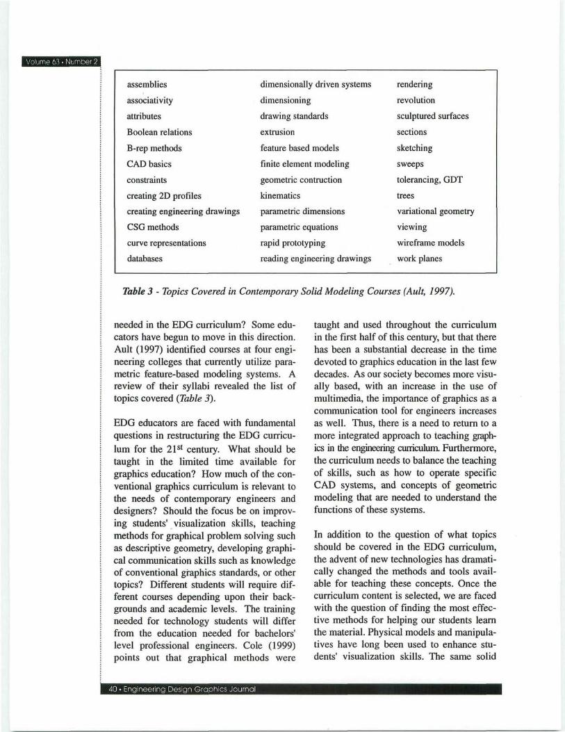
Both types of systems are referred to as constraint-based systems. The most common implementations use a B-Rep modeling strategy, wherein the solid is built from combinations of 2D planar cross sections as described above. Constraints are established between the parameters to control topological integrity and capture design intent. Three types of constraints can be established. Geometric constraints assign relations between points, lines, and other planar curves. Commonly used geometric constraints include symmetry, tangency, perpendicularity, parallelism, coincidence and col-inearity. Figure 6 shows a 2D planar cross section with geometric constraints. The two
V
H
L|
H
1
L| V
Figure 6 - Planar cross section with geometric constraints.
lines labeled LI have equal length. Dimensional constraints control either distances between entities or sizes of the entities. Finally, algebraic constraints or expressions can be written to relate dimension variables to each other or to free variables. Arithmetic functions, trigonometric functions as well as conditional statements may be included. Dimensional and arithmetic constraints are
shown in Figure 5. These equations may impose restrictions on the geometry which are based on functional requirements of the product, thus enabling the designer to capture design intent within the geometric model.
Assembly Modeling and Parts Structure Geometric modeling systems have been extended to include modeling of assembled products as well as the individual components. Assembly modeling utilizes much of the same technology as solid modeling systems, including tree- and graph-based data structures, constraints for placement of components and relationships between dimensions of mating parts, and associativity between part and assembly models. Parts are represented as instances or associative links in the data structure. Thus, changes to a part will automatically be reflected in all assemblies where the part is used. In the design process, assembly models can be used for concept modeling with a top-down approach, wherein the product envelope is loosely defined along with envelopes for the sub assemblies as well as individual parts. The envelope defines a bounding box or region for the part without need for exact geometry. In some cases a skeleton is created to position critical points on the part that are used for assembly of mating parts. This allows multiple designers to work on the design concurrently while still ensuring that the parts will assemble and function proper-
iy.
Alternatively, a bottom-up approach can be used wherein the individual parts are first designed and then placed together in the assembly. This approach is useful when a large number of stock parts or purchased components are used in the design. Solids-based assembly models can be used to check tolerances and fits by performing interference detection, simulate assembly processes and develop assembly sequences, generate bills of materials, and as a precursor to kinematic modeling of mechanisms (Rae, 1995).

Dlume 63 • Number 2
^ex^-r ENG//V MANUFACTURING,
SIMULATION
3-D GEOMETRIC DATABASE
MAINTENANCE
DISPOSAL
Figure 1996).
Use of 3D geometric model in concurrent engineering functions (Barr,
Solid Modeling Applications Geometric models are used to support a wide variety of applications in all fields of engineering and design. Because the solid model provides an unambiguous representation of the object, it can be used to generate accurate renderings for the purposes of visualization, and enables accurate engineering analyses to be performed. For example, in architectural applications, the designer can construct a virtual model and simulate a walk-through of a new building design.
In product modeling, analyses such as determination of mass properties, finite element analyses, and kinematic and dynamic modeling can be performed. Manufacturing applications include process simulation, toolpath generation, tolerance analysis and tooling design. As a powerful visualization tool, solid modeling has been used to study chemical interactions and develop new drugs.
38 • Engineering Design Graphics Journal
Just as the world is populated with a multitude of physical artifacts, so too are the potential applications of solid modeling virtually unbounded. Barr and Juricic (1996) present a model that describes the many uses of the 3D geometric model in a concurrent engineering environment (Figure 7).
Future Directions in Geometric Modeling As we move into the 21s t century, further development of geometric modeling systems will proceed at a rapid pace. Just as feature-based and constraint-based systems developed out of basic solid modelers, future CAD systems will exhibit enhanced functionality to improve productivity of the designer. Geometric modeling is being supplanted by product modeling, which includes not only the geometry of an object, but any information or data that is needed to design, develop, produce and support the product through its entire life cycle.

This effort is proceeding under the auspices of the PDES/STEP (Product Data Exchange Standard/Standard for the Exchange of Product Model Data) standards committees in both the US and Europe (Dincau, 1995). This information may then be used to support computer-based design tools that require more complete information about the product, such as knowledge-based systems and physical simulation.
Applications of geometric modeling will also expand and improve, as the models become more robust and realistic. Research in the past decade has brought new technologies such as virtual reality and rapid prototyping to the stage of commercially available systems, with ongoing improvements in cost and performance. Computer aided design tools that support preliminary design and concept design, and tools to cap
ture and analyze design rationale are current research topics in this area.
Geometric Modeling in a Contemporary EDG Curriculum As these rapid changes in graphics technology take place, engineers need to learn new skills and concepts that enable them to use these new tools effectively. Hanratty (1995) identified a list of concepts needed for a thorough understanding of parametric solid modeling (Table 1).
Compare this list to the concepts identified by Crittendon (1996) as those taught in conventional freshman graphics courses (Table 2). Clearly, there is a mismatch with little overlap in the two lists. If parametric solid modeling is the principal graphics tool used by contemporary engineering designers, does this not imply that dramatic changes are
algebraic functions
assembly
Boolean operations
boundary representation
CSG
dimension driven
dimensionally constrained
entity
features
feature-based modeling
mathematical rectification
parameter
part
rectification
relational rectification
sculptured solid
select
subassembly
topological rectification
transcendental function
variational engine
Table 1 - Concepts in Parametric Solid Modeling (Hanratty, 1995).
descriptive geometry
developments
dimensioning
drafting skills
geometric construction
geometry
graphing
intersections
kinematics
lettering
mathematics
orthographic projection
reading of
engineering drawings scales
sectional views
sketching
software use
solid modeling
threads and fasteners
tolerances
visualization
Table 2 - Concepts Taught in EDG Courses (Crittendon, 1996).
assemblies
associativity
attributes
Boolean relations
B-rep methods
CAD basics
constraints
creating 2D profiles
creating engineering drawings
CSG methods
curve representations
databases
dimensionally driven systems
dimensioning
drawing standards
extrusion
feature based models
finite element modeling
geometric contruction
kinematics
parametric dimensions
parametric equations
rapid prototyping
reading engineering drawings
rendering
revolution
sculptured surfaces
sections
sketching
sweeps
tolerancing, GDT
trees
variational geometry
viewing
wireframe models
work planes
Table 3 - Topics Covered in Contemporary Solid Modeling Courses (Ault, 1997).
needed in the EDG curriculum? Some educators have begun to move in this direction. Ault (1997) identified courses at four engineering colleges that currently utilize parametric feature-based modeling systems. A review of their syllabi revealed the list of topics covered (Table 3).
EDG educators are faced with fundamental questions in restructuring the EDG curriculum for the 21 s t century. What should be taught in the limited time available for graphics education? How much of the conventional graphics curriculum is relevant to the needs of contemporary engineers and designers? Should the focus be on improving students' visualization skills, teaching methods for graphical problem solving such as descriptive geometry, developing graphical communication skills such as knowledge of conventional graphics standards, or other topics? Different students will require different courses depending upon their backgrounds and academic levels. The training needed for technology students will differ from the education needed for bachelors' level professional engineers. Cole (1999) points out that graphical methods were
Design Graphics Jour
taught and used throughout the curriculum in the first half of this century, but that there has been a substantial decrease in the time devoted to graphics education in the last few decades. As our society becomes more visually based, with an increase in the use of multimedia, the importance of graphics as a communication tool for engineers increases as well. Thus, there is a need to return to a more integrated approach to teaching graphics in the engineering curriculum. Furthermore, the curriculum needs to balance the teaching of skills, such as how to operate specific CAD systems, and concepts of geometric modeling that are needed to understand the functions of these systems.
In addition to the question of what topics should be covered in the EDG curriculum, the advent of new technologies has dramatically changed the methods and tools available for teaching these concepts. Once the curriculum content is selected, we are faced with the question of finding the most effective methods for helping our students learn the material. Physical models and manipula-tives have long been used to enhance students' visualization skills. The same solid

modeling technologies that we teach also enable us to use a virtual environment in the form of animated computer models in addition to physical objects. The curriculum may also be improved by implementing new theories in teaching and instructional strategies such as cooperative learning and methods for teaching diverse student populations with varying learning styles. Educators in the fields of mathematics, graphic arts, and fine arts may have curriculum elements that could be useful in teaching new EDG topics.
Conclusions Geometric modeling is a powerful tool for all branches of engineering design. Inclusion of solid modeling in the modern engineering curriculum provides the necessary background for use of this technology by engineering graduates as well as industrial designers, scientists, technical communications majors, and others involved in design, development, analysis and marketing of physical artifacts. Although the basic principles of geometric modeling, descriptive geometry and analytical geometry remain unchanged, additional concepts have been introduced that are fundamental to the understanding of these new technologies. Significant changes in the engineering curriculum are needed to incorporate concepts required to understand and utilize solid and constraint-based modeling in engineering applications (Ault, 1997). Although we must continue to teach some of the traditional topics such as visualization skills, a need for increased emphasis on concepts of solid modeling, parametrics and modern graphical analysis methods is indicated. Alternative teaching methods and the use of modern technologies in the classroom should also be investigated in order to increase the effectiveness of graphics education.
References
Ault, H.K. (1997). Principles of parametrics - new concepts in the EDG curriculum. Proceedings, Engineering Design Graphics
Division Mid-year Conference, ASEE.
Barr, R. & Juricic, D. (1996). Extending engineering design graphics laboratories to have a CAD/CAM component: Implementation issues, Engineering Design Graphics Journal, 60(2), 26-41.
Bertoline, G., Weibe, E., Miller, C , & Mohler, J. (1997). Technical graphics communication. New York, NY: Mc-Graw-Hill.
Chasen, S. (1996). A little history of CA. In Machover, C. (ed.), The CAD/CAM handbook. New York, NY: McGraw-Hill.
Dincau, M.A. (1995). Solid modeling and product exchange using STEP. In LaCourse, D. (ed.), The Handbook of Solid Modeling. New York, NY: McGraw-Hill.
Hanratty, P. (1995). Parametric/relational solid modeling. In LaCourse, D. (ed.), The Handbook of Solid Modeling. New York, NY: McGraw-Hill.
Krouse, J. (1996). What are CAD, CAM, CAE and CIM?. In Machover, C. (ed.), The CAD/CAM handbook. New York, NY: McGraw-Hill.
Lin, V.C, Gossard, D.C., and Light, R.A. (1981). Variational geometry in computer-aided design. Proceedings, SIGGRAPH, ACM.
MicroCad News (1991). "The promise of solid modeling.
Mortenson, M. (1985). Geometric Modeling. (1st ed.) New York, NY: John Wiley & Sons.
Orr, J. (1995). Introducing solid modeling. In LaCourse, D. (ed.), The Handbook of Solid Modeling. New York, NY: McGraw-Hill.
Rae, G. and Hamlet, D. (1995). Solid modeling for assemblies. In LaCourse, D. (ed.), The Handbook of Solid Modeling. New York, NY: McGraw-Hill.

Shah, J. and Mantyla, M. (1995). Parametric and feature-based CAD/CAM. New York, NY: John Wiley & Sons.
Stanford University, Department of Mathematics, Educational Program for Teachers of Mathematics (1998). Challenges of geometry. [Online] http://cartan.stan-ford.edu/eptm/Curriculum/Geometry/ geometry.html.
Thompson, D. (1998). SCIT, University of Wolverhampton, Wolverhampton, UK. Origins of geometry. [Online] http://www. scit.wlv.ac.uk/university/scit/modules/mm2 217/og.htm.
Zeid, I. (1991). CAD/CAM: Theory and practice. New York, NY: McGraw-Hill.
42 • Engineering Design Graphics Journal