3-d numerical simulation of a manual … simulation may be very useful tools for the investiga- ......
TRANSCRIPT

3-D NUMERICAL SIMULATION OF A MANUAL PLASMA CUTTING TORCH
V. Colombo1, G. Cantoro1
, E. Ghedini1, S.Dallavalle2, M. Vancini2
1 Department of mechanical engineering (D.I.E.M.), Alma Mater Studiorum - Università di Bologna, Via Saragozza 8, 40123 Bologna, Italy
2Cebora S.p.A., Via Andrea Costa 24, 40057 Cadriano di Granarolo, Italy
Abstract: the aim of this work is to investigate, by means of a 3-D FLUENT© based numeri-cal model the fluid flow and temperature distribution of a plasma transferred arc discharged inside a manual plasma cutting torch. The detailed gas injection sections and of shield geome-try are included in the domain as well. Keywords: plasma cutting torches, transferred arc plasma torches, metal cutting
1. Introduction
Transferred arc plasma torches are widely used in in-dustrial cutting process of metallic materials because of their ability to cut a wide range of metals and because of the very high productivity they can achieve. The plasma arc cutting process is characterized by a transferred elec-tric arc that is established between an electrode that is part of the cutting torch (the cathode) and another electrode that is the metallic workpiece to be cut (the anode) [1]. In order to obtain a high quality cut and a high productivity, the plasma jet must be, among the other things, as colli-mated as possible and must have the higher achievable power density. With this regards, modelling and numeri-cal simulation may be very useful tools for the investiga-tion of the characteristics of the plasma discharge gener-ated in these kind of devices, as well as for the optimiza-tion of industrial cutting torches. In recent years, numeri-cal simulation has gained popularity as a tool for torch design and a lot of papers have been published on this topic (see, for example, [4-6], just to name but a few).
In this paper we present a three-dimensional numerical model within a customized version of the CFD commer-cial code FLUENT in the framework of a research con-tract between the University of Bologna and Cebora S.p.A. Flow and energy equations are solved for an optically thin air plasma under conditions of LTE, while the electro-magnetic field equations are solved in their scalar and vector potential form [2-4]. Cathode region is taken into account in a simplified way, neglecting the non equili-brium effects of the sheath region. For the sake of sim-plicity, a fictitious anode is placed in the bottom boundary, since the analysis will be performed mainly to understand the plasma behaviour inside the torch. Simulations are performed using a customized CFD commercial code over a network cluster of double processor calculators due
to the large computational requirements of the model and the grid refinement needed for the turbulence model in a full 3-D environment. For the sake of simplicity, a fictious anode is placed in the bottom boundary, since the analysis will be performed mainly to understand the plasma be-haviour inside the torch. The details of the gas injection sections and of shield geometry are included in the com-putational domain in order to determine the effects of the geometry on the flow field characteristic of the discharge and to optimize it in the design phase.
2. Physical-mathematical model
Three-dimensional computational model for the simu-lation of a transferred arc plasma torches required the simultaneous solution of the coupled set of non linear fluid dynamic, electromagnetic and energy transfer equa-tions as done in [2-3]. In the present model, turbulence phenomena are taken into account by means of a k-ε rea-lizable model in order to better describe the flow field inside the device. Since flow inside the plasma torch presents a transitional regime from laminar to turbulent (i.e. the flow is turbulent in the region close to the inlet, nearly laminar inside the nozzle and turbulent again at the nozzle exit), a detailed treatment of the boundary layer is performed using a very fine grid near the walls, in order to capture the details of flow field and the mechanisms of turbulence generation. The main simplifying assumptions on which the devel-oped models rely are:
• stationary discharge; • optically thin plasma; • local thermodynamic equilibrium (LTE);
Taking into account the previous assumptions, the equa-tions of the conservation of the mass and momentum take the following form for the three dimensional case:
0)( =⋅∇ νρ
[1]
LFp +⋅∇+−∇=⋅∇ τννρ )(
[2]
being ρ the density of the fluid, ν the velocity of the fluid, p the pressure, τ the stress tensor and FL the Lorentz force due to the interaction of the conductive fluid and electro-magnetic field. The energy equation is solved without taking into account the viscous dissipation:
[3]
Where h is the enthalpy of the fluid, k is the thermal con-ductivity of the fluid, kB is the Boltzmann constant, e is the electron charge, j
is the current density and Cp is
the specific heat at a constant pressure of the fluid. The last term on the left hand side of the equation represents the enthalpy transport due to stream of the conductive electrons. Finally, QJ is the energy dissipated in the dis-charge by joule effect and QR represents the radiative losses. The equations for the calculation of the electrostatic po-tential V, and of the vector potential A
, are the follow-
ing:
0=∇⋅∇ Vσ [4]
[5]
Where σ is the electrical conductibility of the plasma, VEj ∇−== σσ
represents the current density and μ0
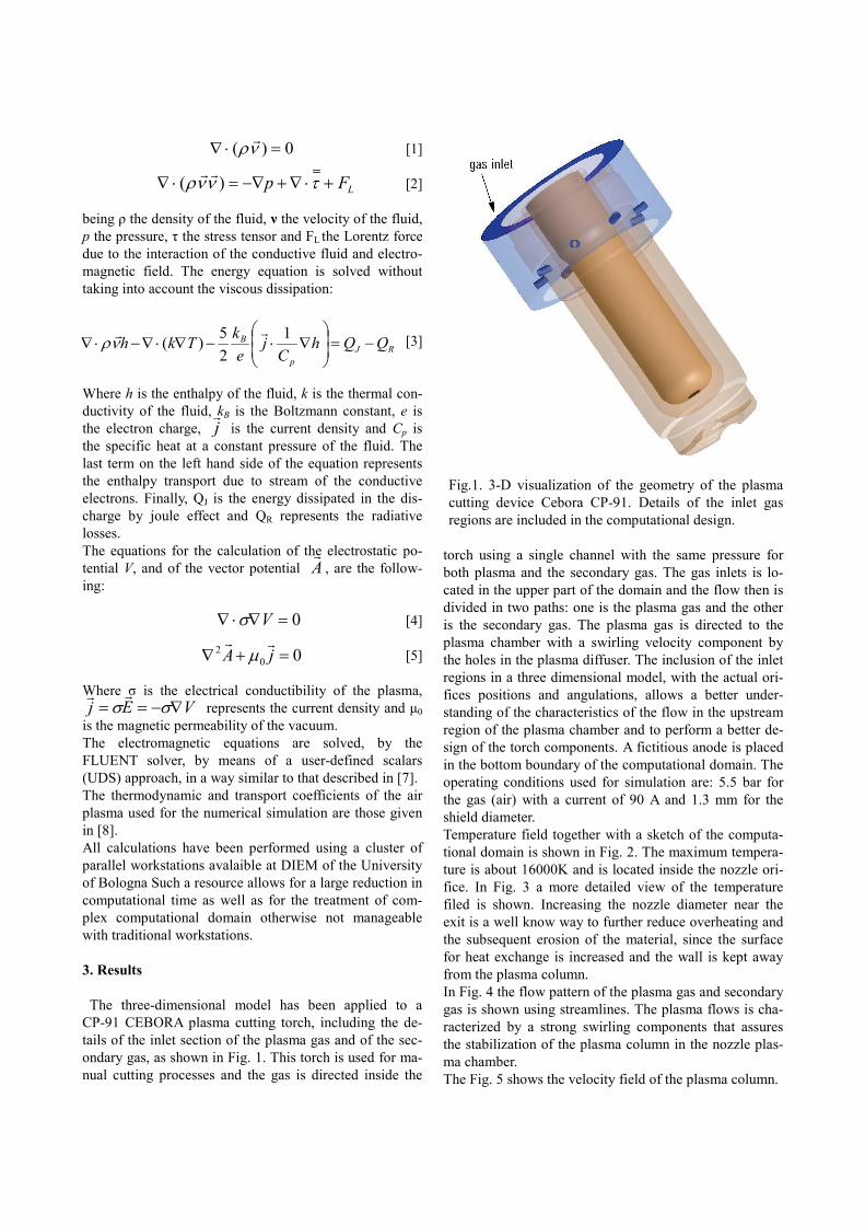
is the magnetic permeability of the vacuum. The electromagnetic equations are solved, by the FLUENT solver, by means of a user-defined scalars (UDS) approach, in a way similar to that described in [7]. The thermodynamic and transport coefficients of the air plasma used for the numerical simulation are those given in [8]. All calculations have been performed using a cluster of parallel workstations avalaible at DIEM of the University of Bologna Such a resource allows for a large reduction in computational time as well as for the treatment of com-plex computational domain otherwise not manageable with traditional workstations. 3. Results The three-dimensional model has been applied to a CP-91 CEBORA plasma cutting torch, including the de-tails of the inlet section of the plasma gas and of the sec-ondary gas, as shown in Fig. 1. This torch is used for ma-nual cutting processes and the gas is directed inside the
torch using a single channel with the same pressure for both plasma and the secondary gas. The gas inlets is lo-cated in the upper part of the domain and the flow then is divided in two paths: one is the plasma gas and the other is the secondary gas. The plasma gas is directed to the plasma chamber with a swirling velocity component by the holes in the plasma diffuser. The inclusion of the inlet regions in a three dimensional model, with the actual ori-fices positions and angulations, allows a better under-standing of the characteristics of the flow in the upstream region of the plasma chamber and to perform a better de-sign of the torch components. A fictitious anode is placed in the bottom boundary of the computational domain. The operating conditions used for simulation are: 5.5 bar for the gas (air) with a current of 90 A and 1.3 mm for the shield diameter. Temperature field together with a sketch of the computa-tional domain is shown in Fig. 2. The maximum tempera-ture is about 16000K and is located inside the nozzle ori-fice. In Fig. 3 a more detailed view of the temperature filed is shown. Increasing the nozzle diameter near the exit is a well know way to further reduce overheating and the subsequent erosion of the material, since the surface for heat exchange is increased and the wall is kept away from the plasma column. In Fig. 4 the flow pattern of the plasma gas and secondary gas is shown using streamlines. The plasma flows is cha-racterized by a strong swirling components that assures the stabilization of the plasma column in the nozzle plas-ma chamber. The Fig. 5 shows the velocity field of the plasma column.
Fig.1. 3-D visualization of the geometry of the plasma cutting device Cebora CP-91. Details of the inlet gas regions are included in the computational design.
RJp
B QQhC
je
kTkh −=
∇⋅−∇⋅∇−⋅∇
125)(
νρ
002 =+∇ jA
µ
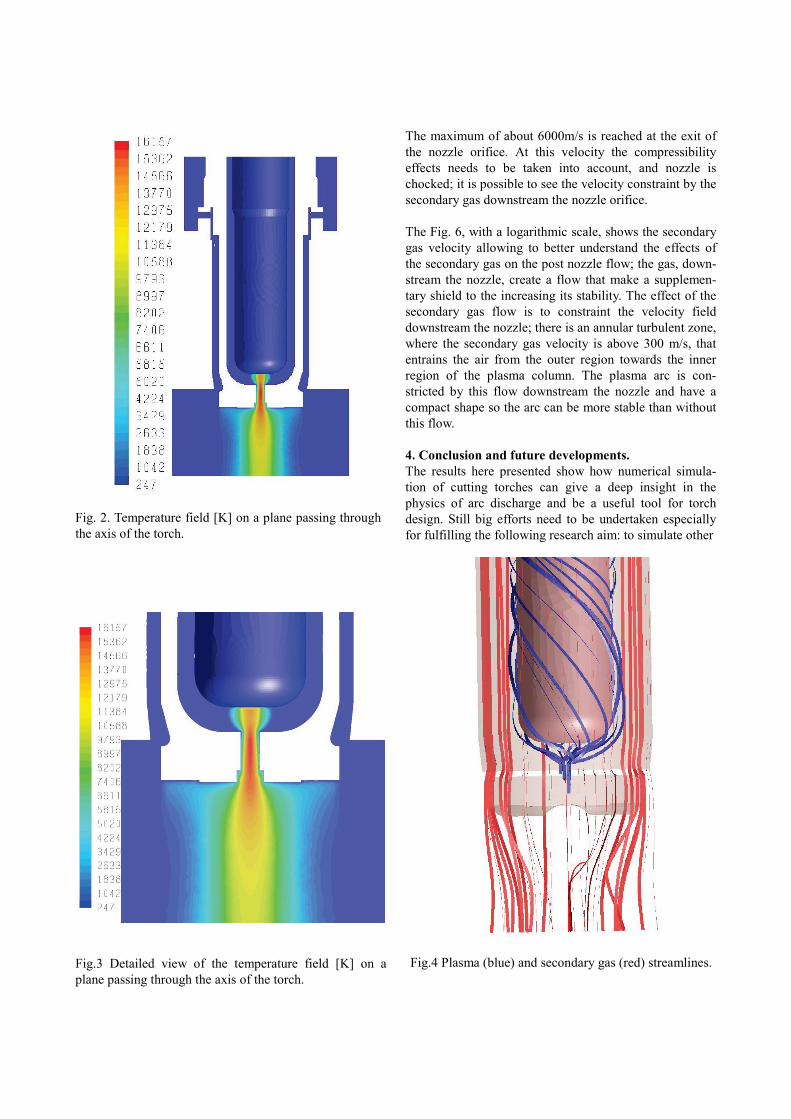
Fig.3 Detailed view of the temperature field [K] on a plane passing through the axis of the torch.
The maximum of about 6000m/s is reached at the exit of the nozzle orifice. At this velocity the compressibility effects needs to be taken into account, and nozzle is chocked; it is possible to see the velocity constraint by the secondary gas downstream the nozzle orifice. The Fig. 6, with a logarithmic scale, shows the secondary gas velocity allowing to better understand the effects of the secondary gas on the post nozzle flow; the gas, down-stream the nozzle, create a flow that make a supplemen-tary shield to the increasing its stability. The effect of the secondary gas flow is to constraint the velocity field downstream the nozzle; there is an annular turbulent zone, where the secondary gas velocity is above 300 m/s, that entrains the air from the outer region towards the inner region of the plasma column. The plasma arc is con-stricted by this flow downstream the nozzle and have a compact shape so the arc can be more stable than without this flow. 4. Conclusion and future developments. The results here presented show how numerical simula-tion of cutting torches can give a deep insight in the physics of arc discharge and be a useful tool for torch design. Still big efforts need to be undertaken especially for fulfilling the following research aim: to simulate other
Fig. 2. Temperature field [K] on a plane passing through the axis of the torch.
Fig.4 Plasma (blue) and secondary gas (red) streamlines.

commercial plasma torches to draw useful comparisons between competing technologies; to fully simulate the electrode region; to find a useful link between simulations and experiment to predict and optimize cut quality results; improve parallelization to efficiently use plasma simula-tion for industrial time scale. References. [1] V. A. Nemchinsky and W. S. Severance, “What we
know and what we know not about plasma arc cut-ting”, J. Phys. D: Appl. Phys., 39, R423-R438, (2006).
[2] V. Colombo, S. Dallavalle, E. Ghedini, G. Masini, D. Russo, M. Vancini, “2-D And 3-D fluidynamic and plasma characterization of DC transferred arc plasma torches for metal cutting”, J. of High Temperature Material Processes, 10, pp. 379 - 392 (2006)
[3] V. Colombo, A. Concetti, S. Dallavalle, E. Ghedini, M. Vancini, “Understanding plasma fluid dynamics inside plasma torches through advanced modeling”, IEEE Trans. Plasma Sci., 36, 389-402 (2007)
[4] P Freton,J J Gonzalez, F Camy Peyret and A Gleizes, “Complementary experimental and theoretical approaches to the determination of the plasma cha-racteristics in a cutting plasma torch”, Journal of Physics D:Applied Physics, 36 (2003) 1269-1283.
[5] V.A. Nemchinsky, “Plasma flow in a nozzle during arc cutting”, J. Phys. D: Appl. Phys. 31,3102-3107, 1998.
[6] J. Gonzalez-Aguilar, C. Pardo Sanjuro, A. Rodri-guez-Yunta, M. Angel Garcia Calderon, “A theoreti-cal study of a cutting air plasma torch”, IEEE Trans-action on plasma science, 27, 1, 1999.
[7] D. Bernardi, V. Colombo, E. Ghedini, A. Mentrelli, “Comparison of different techniques for the FLUENT-based treatment of the electromagnetic field in inductively-coupled plasma torches, Eur. Phys. J. D. 27, 1, 55-72, 2003.
[8] M. Capitelli, G. Colonna, C. Gorse, A. D’Angola, “Transport properties of high temperature air in local thermodynamic equilibrium” , Eur. Phys. J. D., 11, 279-289, 2000.
Acknowledgments. Funding from D.I.E.M./Cebora S.p.A. research contract on project MIUR-D.M.28562 (Art.12EMec) and UniBo Strategic Project 2006-PLASMACUT is acknowledged.
Fig. 5. Plasma arc velocity [m/s].
Fig. 6 Plasma arc velocity [m/s] in logarithmic scale.