3½ digit voltmeter module led- / lcd- series · 3½ digit voltmeter module led- / lcd- series...
TRANSCRIPT

EA 4035-SERIES
ZEPPELINSTRASSE 19 · D- 82205 GILCHINGTEL 08105/778090 ·FAX 08105/778099 · http://www.lcd-module.de
12.02
3½ DIGIT VOLTMETER MODULELED- / LCD- SERIES
FEATURES
* IP65* 2 LED AND 2 LCD TYPES* EASY TO USE OR COMPATIBLE TO DATEL* ±200mV D.C. FULL SCALE READING
ORDERING INFORMATION
3½-ST. DVM MODULE, 5V, 2x6 PIN, LED RED EA 4035-100S3½-ST. DVM MODULE, 5V, 2x6 PIN, LCD WITH BACKLIGHT EA 4035-200S3½-ST. DVM MODULE, 5V, 1x8 PIN, LED RED EA 4035-300S3½-ST. DVM MODULE, 5V, 1x9 PIN, LCD WITH BACKLIGHT EA 4035-400S
35,1x22,4 mm
Splashpr
oof

EA 4035-100S
ZEPPELINSTRASSE 19 · D- 82205 GILCHINGTEL 08105/778090 ·FAX 08105/778099 · http://www.lcd-module.de
12.01
3½ DIGIT LED VOLTMETER MODULE
FEATURES
* 200mV D.C. FULL SCALE READING* typ. 50mA @ +5V±5% D.C. POWER SUPPLY* BRIGHT RED* 9.4mm (0.37") DIGIT HEIGHT* PROGRAMMABLE DECIMAL POINTS* LED DISPLAY* DISPLAY BLANKING FACILITY* SPLASH PROOF* AUTO-ZERO AND AUTO-POLARITY
35,1x22,4 mm
ORDERING INFORMATION
3½-ST. DVM MODULE, 5V, 2x6 PIN, LED RED EA 4035-100S
Splashproof

2
EA 4035-100SPRODUCT DESCRIPTIONThe EA 4035-100S features a 200mV d.c. measurement range with auto-zero and auto-polarity.Decimal points are user selectable. The EA 4035-100S features a negative rail generator whichenables the meter to measure a signal referenced to its own power supply 0V. The bright red LEDdisplay ensures excellent readability under low light conditions. It can be blanked in applicationsrequiring low power operation. The module is easily fitted into the panel, using the fixing clip provided.The module’s low cost means it will suit high and low volume applications. The design of the panelmeter’s housing and seal ensures splash proofing in many applications.
SAFETYTo comply with the Low Voltage Directive (LVD93/68/EEC), input voltages to the module's pins mustnot exceed 60Vdc. The user must ensure that the incorporation of the panel meter into the user'sequipment conformsto the relevant sections of BS EN 61010 (Safety Requirements for ElectricalEquipment for Measuring, Control and Laboratory Use).
PANEL FITTING
CIRCUIT DIAGRAM
3
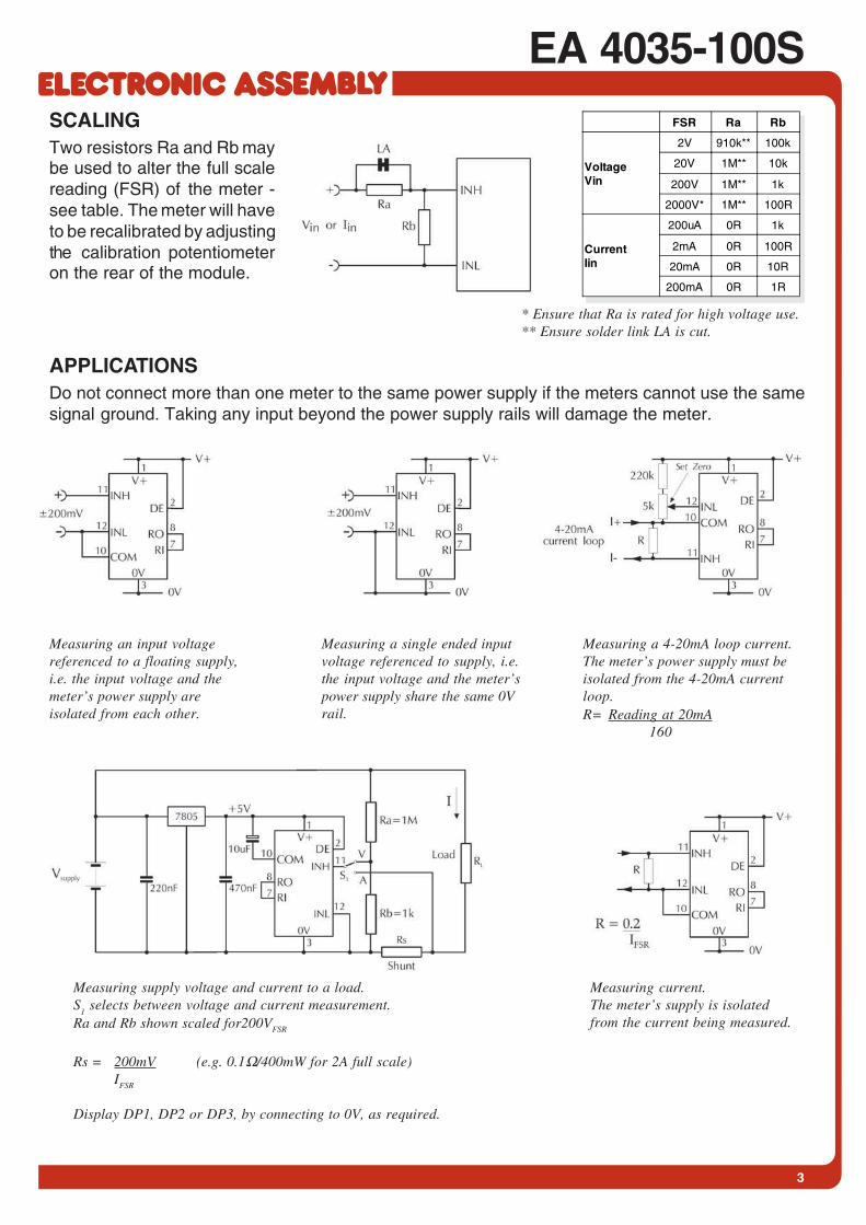
EA 4035-100SSCALINGTwo resistors Ra and Rb maybe used to alter the full scalereading (FSR) of the meter -see table. The meter will haveto be recalibrated by adjustingthe calibration potentiometeron the rear of the module.
APPLICATIONSDo not connect more than one meter to the same power supply if the meters cannot use the samesignal ground. Taking any input beyond the power supply rails will damage the meter.
Measuring an input voltagereferenced to a floating supply,i.e. the input voltage and themeter’s power supply areisolated from each other.
Measuring a single ended inputvoltage referenced to supply, i.e.the input voltage and the meter’spower supply share the same 0Vrail.
Measuring a 4-20mA loop current.The meter’s power supply must beisolated from the 4-20mA currentloop.R= Reading at 20mA
160
Measuring current.The meter’s supply is isolatedfrom the current being measured.
Measuring supply voltage and current to a load.S
1 selects between voltage and current measurement.
Ra and Rb shown scaled for200VFSR
Rs = 200mV (e.g. 0.1Ω/400mW for 2A full scale)IFSR
Display DP1, DP2 or DP3, by connecting to 0V, as required.
FSR Ra Rb
VoltageVin
2V 910k** 100k
20V 1M** 10k
200V 1M** 1k
2000V* 1M** 100R
CurrentIin
200uA 0R 1k
2mA 0R 100R
20mA 0R 10R
200mA 0R 1R
* Ensure that Ra is rated for high voltage use.** Ensure solder link LA is cut.

EA 4035-100S
ZEPPELINSTRASSE 19 · D- 82205 GILCHINGTEL 08105/778090 ·FAX 08105/778099 · http://www.lcd-module.de
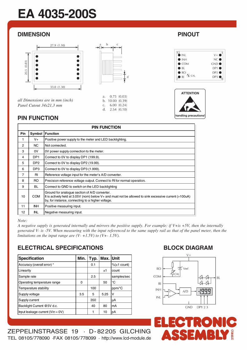
DIMENSION PINOUT
all Dimensions are in mm (inch)Panel Cutout 34x21,3 mm
PIN FUNCTIONPin Symbol Function
1 V+ Positive power supply to the meter.
2 DEDisplay Enable. Connect to V+ for normal operation.Do not connect to enter low power mode.The display is then blanked, but the voltmeter section continuesto operate. In low power mode, the current consumption is reduced to 400uA (typ).
3 0V 0V power supply connection to the meter.
4 DP1 Connect to 0V to display DP1 (199.9).
5 DP2 Connect to 0V to display DP2 (19.99).
6 DP3 Connect to 0V to display DP3 (1.999).
7 RI Reference voltage input for the meter’s A/D converter.
8 RO Precision reference voltage output. Connect to RI for normal operation.
9 T Connect to V+ to test the display. All segments will be displayed, except for decimal points.
10 COMGround for analogue section of A/D converter.It is actively held at 3.05V (nom) below V+ and must not be allowed to sink excessive current (>100uA)by, for instance, connecting to a higher voltage.
11 INH Positive measuring input.
12 INL Negative measuring input.
PIN FUNCTION
ELECTRICAL SPECIFICATIONS BLOCK DIAGRAM
Specification Min. Typ. Max. UnitAccuracy (overall error) * 0.1 %(±1 count)
Linearity ±1 count
Sample rate 2.5 samples/sec
Operating temperature range 0 50 °C
Warm-up time 10 minute
Temperature stability 150 ppm/°C
Supply voltage 4.75 5 5.25 V
Supply current (DE connected to V+) 50 90 mA
Supply current (DE connected to 0V) 400 uA
Input leakage current (Vin = 0V) 1 10 pA
ATTENTION
handling precautions!
EA 4035-200S
ZEPPELINSTRASSE 19 · D- 82205 GILCHINGTEL 08105/778090 ·FAX 08105/778099 · http://www.lcd-module.de
12.01
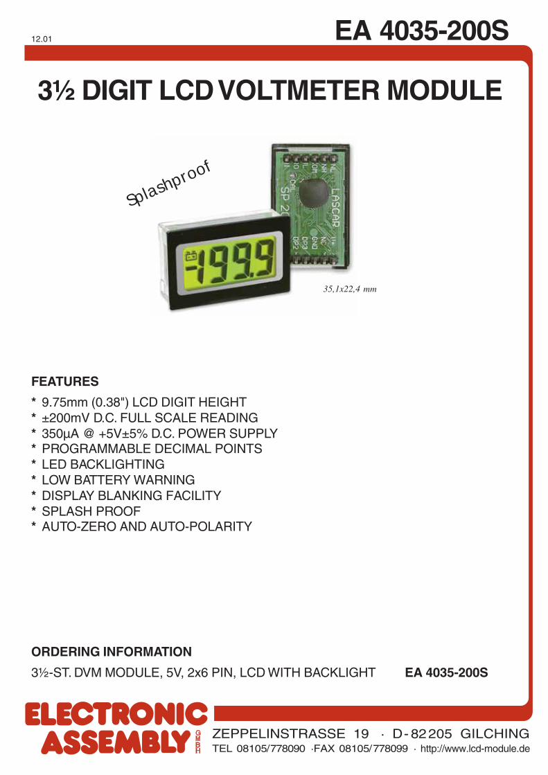
3½ DIGIT LCD VOLTMETER MODULE
FEATURES
* 9.75mm (0.38") LCD DIGIT HEIGHT* ±200mV D.C. FULL SCALE READING* 350µA @ +5V±5% D.C. POWER SUPPLY* PROGRAMMABLE DECIMAL POINTS* LED BACKLIGHTING* LOW BATTERY WARNING* DISPLAY BLANKING FACILITY* SPLASH PROOF* AUTO-ZERO AND AUTO-POLARITY
35,1x22,4 mm
ORDERING INFORMATION
3½-ST. DVM MODULE, 5V, 2x6 PIN, LCD WITH BACKLIGHT EA 4035-200S
Splashproof
2
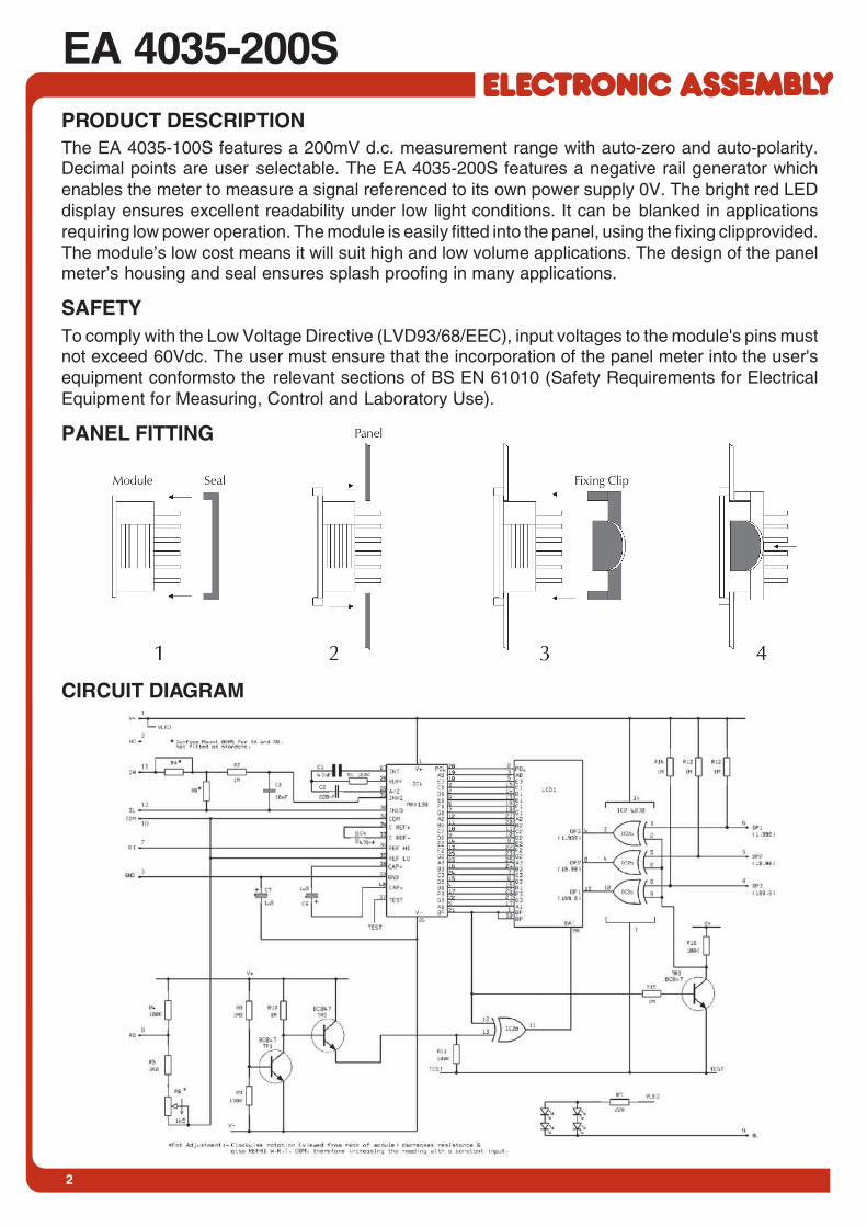
EA 4035-200SPRODUCT DESCRIPTIONThe EA 4035-100S features a 200mV d.c. measurement range with auto-zero and auto-polarity.Decimal points are user selectable. The EA 4035-200S features a negative rail generator whichenables the meter to measure a signal referenced to its own power supply 0V. The bright red LEDdisplay ensures excellent readability under low light conditions. It can be blanked in applicationsrequiring low power operation. The module is easily fitted into the panel, using the fixing clip provided.The module’s low cost means it will suit high and low volume applications. The design of the panelmeter’s housing and seal ensures splash proofing in many applications.
SAFETYTo comply with the Low Voltage Directive (LVD93/68/EEC), input voltages to the module's pins mustnot exceed 60Vdc. The user must ensure that the incorporation of the panel meter into the user'sequipment conformsto the relevant sections of BS EN 61010 (Safety Requirements for ElectricalEquipment for Measuring, Control and Laboratory Use).
PANEL FITTING
CIRCUIT DIAGRAM
3
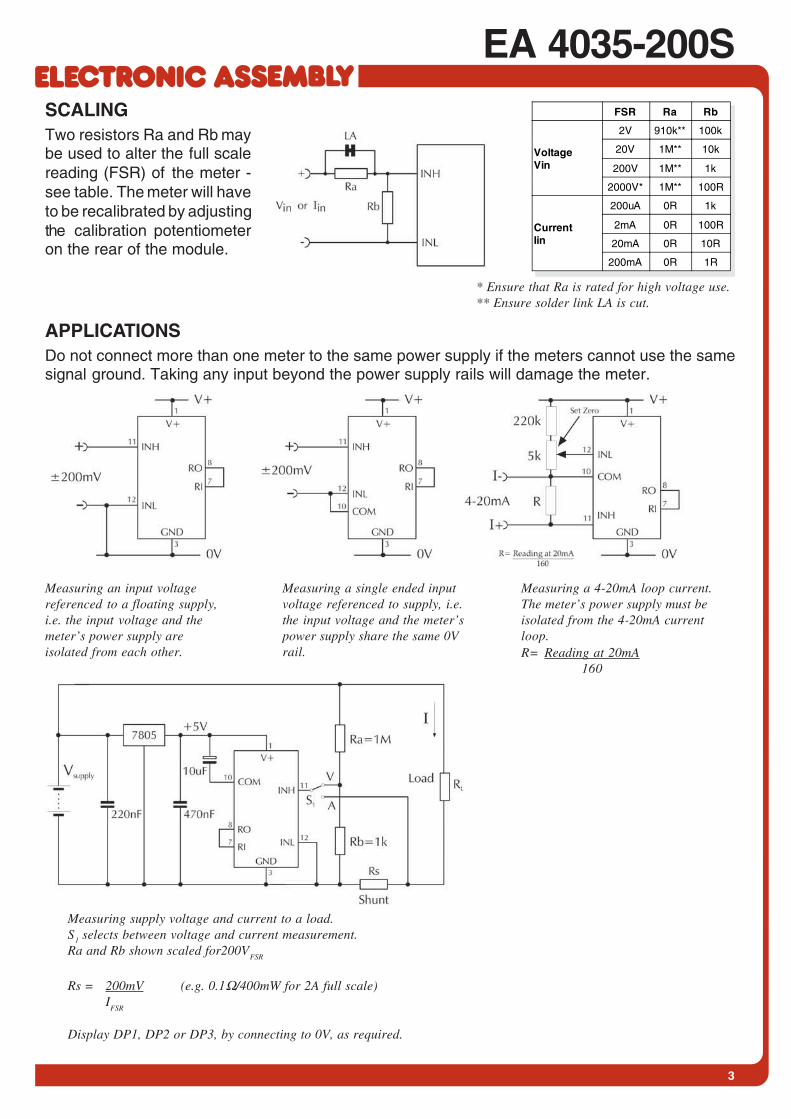
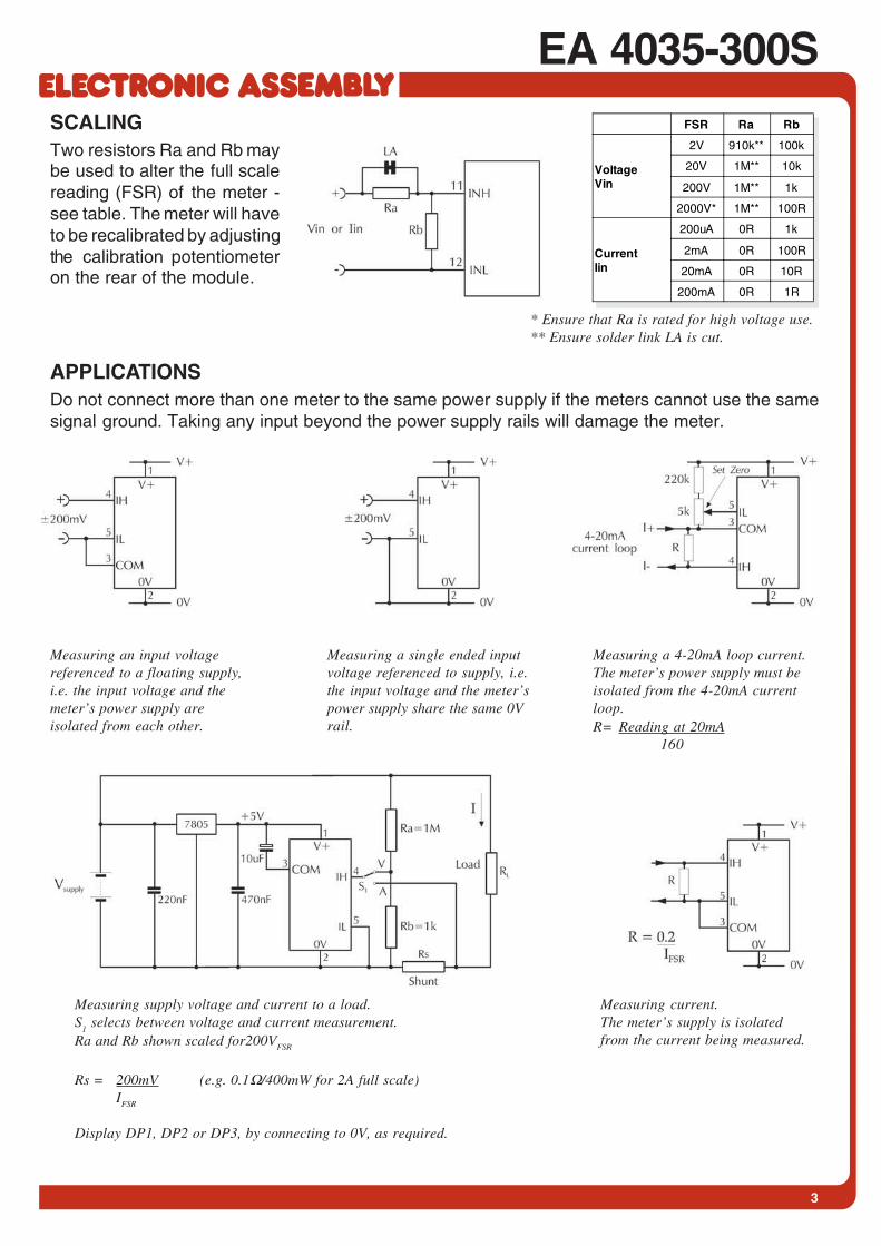
EA 4035-200SSCALINGTwo resistors Ra and Rb maybe used to alter the full scalereading (FSR) of the meter -see table. The meter will haveto be recalibrated by adjustingthe calibration potentiometeron the rear of the module.
APPLICATIONSDo not connect more than one meter to the same power supply if the meters cannot use the samesignal ground. Taking any input beyond the power supply rails will damage the meter.
Measuring an input voltagereferenced to a floating supply,i.e. the input voltage and themeter’s power supply areisolated from each other.
Measuring a single ended inputvoltage referenced to supply, i.e.the input voltage and the meter’spower supply share the same 0Vrail.
Measuring a 4-20mA loop current.The meter’s power supply must beisolated from the 4-20mA currentloop.R= Reading at 20mA
160
Measuring supply voltage and current to a load.S1 selects between voltage and current measurement.Ra and Rb shown scaled for200V
FSR
Rs = 200mV (e.g. 0.1Ω/400mW for 2A full scale)I
FSR
Display DP1, DP2 or DP3, by connecting to 0V, as required.
FSR Ra Rb
VoltageVin
2V 910k** 100k
20V 1M** 10k
200V 1M** 1k
2000V* 1M** 100R
CurrentIin
200uA 0R 1k
2mA 0R 100R
20mA 0R 10R
200mA 0R 1R
* Ensure that Ra is rated for high voltage use.** Ensure solder link LA is cut.
EA 4035-200S
ZEPPELINSTRASSE 19 · D- 82205 GILCHINGTEL 08105/778090 ·FAX 08105/778099 · http://www.lcd-module.de
DIMENSION PINOUT
all Dimensions are in mm (inch)Panel Cutout 34x21,3 mm
PIN FUNCTION
ELECTRICAL SPECIFICATIONS BLOCK DIAGRAM
Specification Min. Typ. Max. UnitAccuracy (overall error) * 0.1 %(±1 count)
Linearity ±1 count
Sample rate 2.5 samples/sec
Operating temperature range 0 50 °C
Temperature stability 100 ppm/°C
Supply voltage 3.5 5 5.25 V
Supply current 350 µA
Backlight Current @5V d.c. 40 80 mA
Input leakage current (Vin = 0V) 1 10 pA
ATTENTION
handling precautions!
PIN FUNCTIONPin Symbol Function
1 V+ Positive power supply to the meter and LED backlighting.
2 NC Not connected.
3 0V 0V power supply connection to the meter.
4 DP1 Connect to 0V to display DP1 (199.9).
5 DP2 Connect to 0V to display DP2 (19.99).
6 DP3 Connect to 0V to display DP3 (1.999).
7 RI Reference voltage input for the meter’s A/D converter.
8 RO Precision reference voltage output. Connect to RI for normal operation.
9 BL Connect to GND to switch on the LED backlighting
10 COMGround for analogue section of A/D converter.It is actively held at 3.05V (nom) below V+ and must not be allowed to sink excessive current (>100uA)by, for instance, connecting to a higher voltage.
11 INH Positive measuring input.
12 INL Negative measuring input.
Note:A negative supply is generated internally and mirrors the positive supply. For example: if V+is +5V, then the internallygenerated V- is -5V. When measuring with the input referenced to the same supply rail as that of the panel meter, then thelimitations on the input range are (V- +1.5V) to (V+- 1.5V).

EA 4035-300S
ZEPPELINSTRASSE 19 · D- 82205 GILCHINGTEL 08105/778090 ·FAX 08105/778099 · http://www.lcd-module.dede
12.01
3½ DIGIT LED VOLTMETER MODULE
FEATURES
* ±200mV D.C. FULL SCALE READING* typ. 50mA @ +5V±5% D.C. POWER SUPPLY* BRIGHT RED* 9.4mm (0.37") DIGIT HEIGHT* PROGRAMMABLE DECIMAL POINTS* BRIGHT RED LED DISPLAY* SIMPLYFIED CONNECTION* SPLASH PROOF* AUTO-ZERO AND AUTO-POLARITY
35,1x22,4 mm
ORDERING INFORMATION
3½-ST. DVM MODULE, 5V, 1x8 PIN, LED RED EA 4035-300S
Splashproof

2
EA 4035-300SPRODUCT DESCRIPTIONThe EA 4035-300S features a 200mV d.c. measurement range with auto-zero and auto-polarity.Decimal points are user selectable. The EA 4035-300S features a negative rail generator whichenables the meter to measure a signal referenced to its own power supply 0V. The bright red LEDdisplay ensures excellent readability under low light conditions. It can be blanked in applicationsrequiring low power operation. The module is easily fitted into the panel, using the fixing clip provided.The module’s low cost means it will suit high and low volume applications. The design of the panelmeter’s housing and seal ensures splash proofing in many applications.
SAFETYTo comply with the Low Voltage Directive (LVD93/68/EEC), input voltages to the module's pins mustnot exceed 60Vdc. The user must ensure that the incorporation of the panel meter into the user'sequipment conformsto the relevant sections of BS EN 61010 (Safety Requirements for ElectricalEquipment for Measuring, Control and Laboratory Use).
PANEL FITTING
CIRCUIT DIAGRAM
3
EA 4035-300SSCALINGTwo resistors Ra and Rb maybe used to alter the full scalereading (FSR) of the meter -see table. The meter will haveto be recalibrated by adjustingthe calibration potentiometeron the rear of the module.
APPLICATIONSDo not connect more than one meter to the same power supply if the meters cannot use the samesignal ground. Taking any input beyond the power supply rails will damage the meter.
Measuring an input voltagereferenced to a floating supply,i.e. the input voltage and themeter’s power supply areisolated from each other.
Measuring a single ended inputvoltage referenced to supply, i.e.the input voltage and the meter’spower supply share the same 0Vrail.
Measuring a 4-20mA loop current.The meter’s power supply must beisolated from the 4-20mA currentloop.R= Reading at 20mA
160
Measuring current.The meter’s supply is isolatedfrom the current being measured.
Measuring supply voltage and current to a load.S
1 selects between voltage and current measurement.
Ra and Rb shown scaled for200VFSR
Rs = 200mV (e.g. 0.1Ω/400mW for 2A full scale)IFSR
Display DP1, DP2 or DP3, by connecting to 0V, as required.
FSR Ra Rb
VoltageVin
2V 910k** 100k
20V 1M** 10k
200V 1M** 1k
2000V* 1M** 100R
CurrentIin
200uA 0R 1k
2mA 0R 100R
20mA 0R 10R
200mA 0R 1R
* Ensure that Ra is rated for high voltage use.** Ensure solder link LA is cut.

EA 4035-300S
ZEPPELINSTRASSE 19 · D- 82205 GILCHINGTEL 08105/778090 ·FAX 08105/778099 · http://www.lcd-module.de
DIMENSION PINOUT
all Dimensions are in mm (inch)Panel Cutout 34x21,3 mm
PIN FUNCTIONPin Symbol Function
1 V+ Positive power supply to the meter.
2 0V 0V power supply connection to the meter.
3 COMGround for analogue section of A/D converter.It is actively held at 3.05V (nom) below V+ and must not be allowed to sink excessive current (>100uA)by, for instance, connecting to a higher voltage.
4 INH Positive measuring input.
5 INL Negative measuring input.
6 DP1 Connect to 0V to display DP1 (199.9).
7 DP2 Connect to 0V to display DP2 (19.99).
8 DP3 Connect to 0V to display DP3 (1.999).
PIN FUNCTION
ELECTRICAL SPECIFICATIONS BLOCK DIAGRAM
Specification Min. Typ. Max. UnitAccuracy (overall error) * 0.1 %(±1 count)
Linearity ±1 count
Sample rate 2.5 samples/sec
Operating temperature range 0 50 °C
Warm-up time 10 minute
Temperature stability 150 ppm/°C
Supply voltage 4.75 5 5.25 V
Supply current 50 90 mA
Input leakage current (Vin = 0V) 1 10 pA
ATTENTION
handling precautions!
Solder Link:LCOM Normally Open. Connects INL to COM.
EA 4035-400S
ZEPPELINSTRASSE 19 · D- 82205 GILCHINGTEL 08105/778090 ·FAX 08105/778099 · http://www.lcd-module.de
12.02
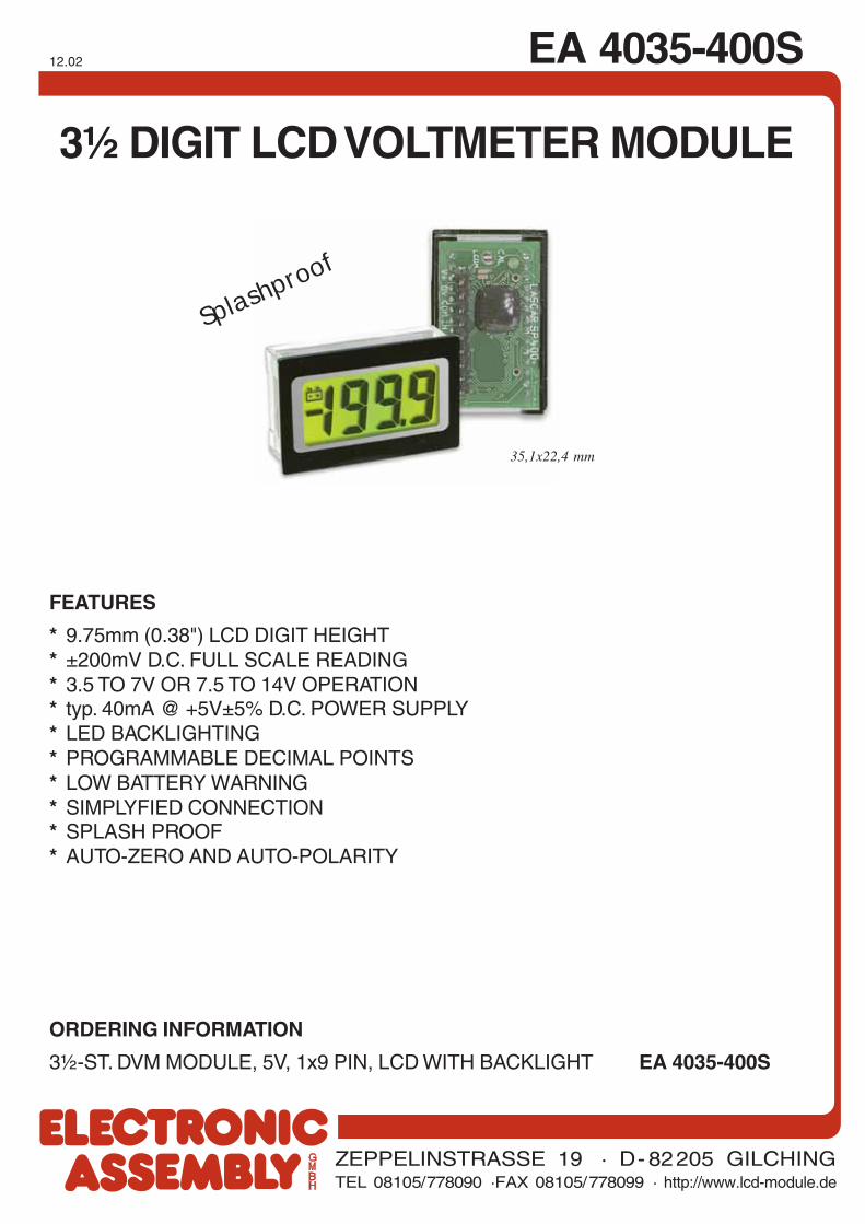
3½ DIGIT LCD VOLTMETER MODULE
FEATURES
* 9.75mm (0.38") LCD DIGIT HEIGHT* ±200mV D.C. FULL SCALE READING* 3.5 TO 7V OR 7.5 TO 14V OPERATION* typ. 40mA @ +5V±5% D.C. POWER SUPPLY* LED BACKLIGHTING* PROGRAMMABLE DECIMAL POINTS* LOW BATTERY WARNING* SIMPLYFIED CONNECTION* SPLASH PROOF* AUTO-ZERO AND AUTO-POLARITY
35,1x22,4 mm
ORDERING INFORMATION
3½-ST. DVM MODULE, 5V, 1x9 PIN, LCD WITH BACKLIGHT EA 4035-400S
Splashproof
2
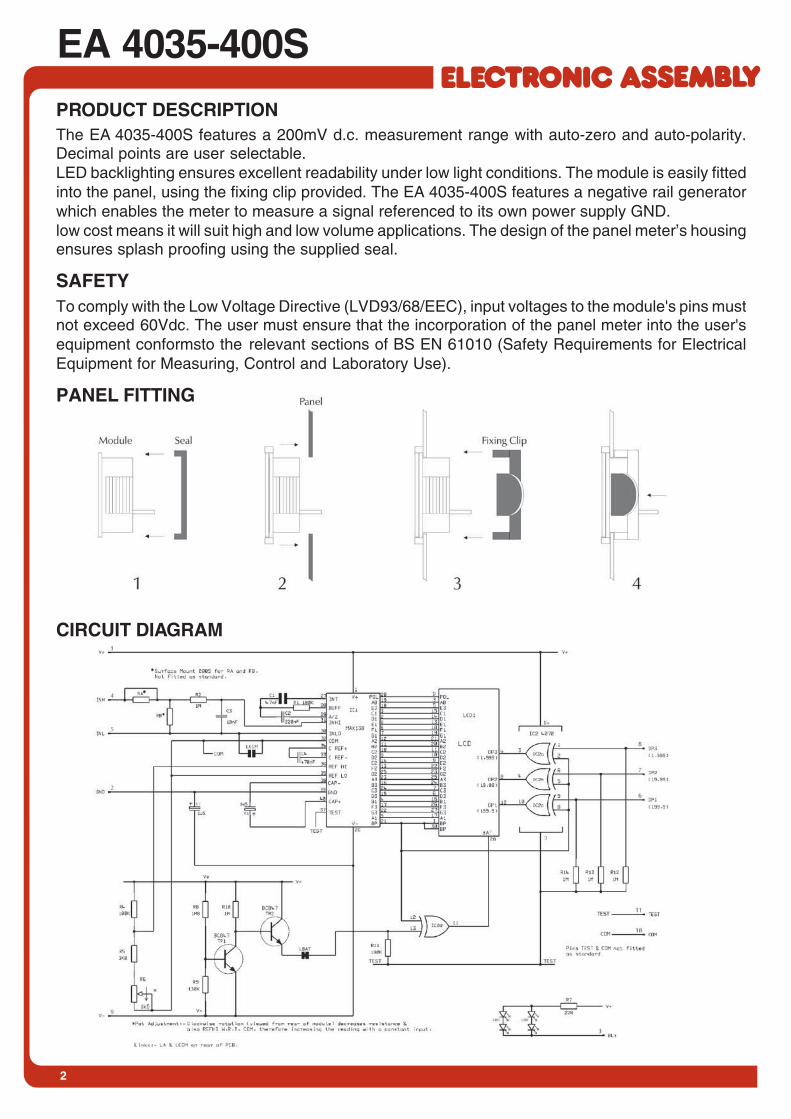
EA 4035-400SPRODUCT DESCRIPTIONThe EA 4035-400S features a 200mV d.c. measurement range with auto-zero and auto-polarity.Decimal points are user selectable.LED backlighting ensures excellent readability under low light conditions. The module is easily fittedinto the panel, using the fixing clip provided. The EA 4035-400S features a negative rail generatorwhich enables the meter to measure a signal referenced to its own power supply GND.low cost means it will suit high and low volume applications. The design of the panel meter’s housingensures splash proofing using the supplied seal.
SAFETYTo comply with the Low Voltage Directive (LVD93/68/EEC), input voltages to the module's pins mustnot exceed 60Vdc. The user must ensure that the incorporation of the panel meter into the user'sequipment conformsto the relevant sections of BS EN 61010 (Safety Requirements for ElectricalEquipment for Measuring, Control and Laboratory Use).
PANEL FITTING
CIRCUIT DIAGRAM
3
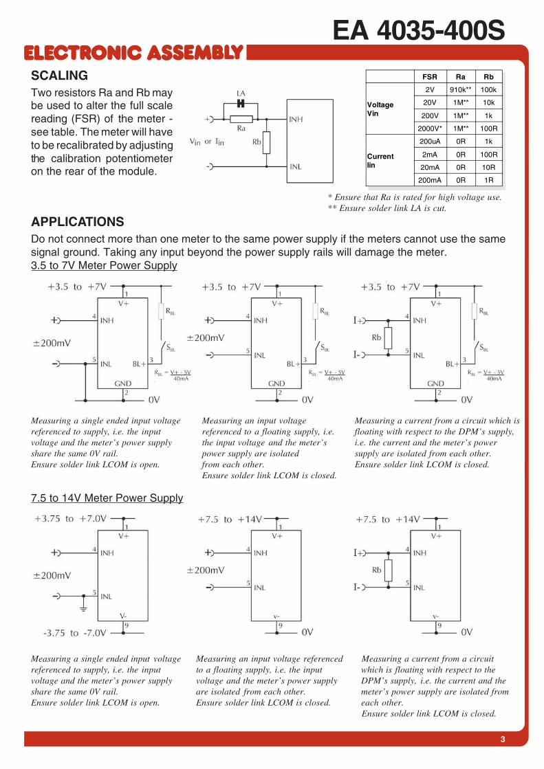
EA 4035-400SSCALINGTwo resistors Ra and Rb maybe used to alter the full scalereading (FSR) of the meter -see table. The meter will haveto be recalibrated by adjustingthe calibration potentiometeron the rear of the module.
APPLICATIONSDo not connect more than one meter to the same power supply if the meters cannot use the samesignal ground. Taking any input beyond the power supply rails will damage the meter.3.5 to 7V Meter Power Supply
FSR Ra Rb
VoltageVin
2V 910k** 100k
20V 1M** 10k
200V 1M** 1k
2000V* 1M** 100R
CurrentIin
200uA 0R 1k
2mA 0R 100R
20mA 0R 10R
200mA 0R 1R
* Ensure that Ra is rated for high voltage use.** Ensure solder link LA is cut.
Measuring a single ended input voltagereferenced to supply, i.e. the inputvoltage and the meter’s power supplyshare the same 0V rail.Ensure solder link LCOM is open.
Measuring an input voltagereferenced to a floating supply, i.e.the input voltage and the meter’spower supply are isolatedfrom each other.Ensure solder link LCOM is closed.
Measuring a current from a circuit which isfloating with respect to the DPM’s supply,i.e. the current and the meter’s powersupply are isolated from each other.Ensure solder link LCOM is closed.
Measuring a single ended input voltagereferenced to supply, i.e. the inputvoltage and the meter’s power supplyshare the same 0V rail.Ensure solder link LCOM is open.
Measuring an input voltage referencedto a floating supply, i.e. the inputvoltage and the meter’s power supplyare isolated from each other.Ensure solder link LCOM is closed.
Measuring a current from a circuitwhich is floating with respect to theDPM’s supply, i.e. the current and themeter’s power supply are isolated fromeach other.Ensure solder link LCOM is closed.
7.5 to 14V Meter Power Supply

EA 4035-400S
ZEPPELINSTRASSE 19 · D- 82205 GILCHINGTEL 08105/778090 ·FAX 08105/778099 · http://www.lcd-module.de
DIMENSION PINOUT
all Dimensions are in mm (inch)Panel Cutout 34x21,3 mm
PIN FUNCTIONPin Symbol Function
1 V+ Positive power supply to the meter
2 GND 0V power supply connection to the meter (3.0 to 7.5V meter power supply appl. only)
3 BL-Connect to meter's negative supply GND or V- to switch on the LED backlightingFor meter supply above 5V, add a series resistor Rs
4 INH Positive measuring input
5 INL Negative measuring input
6 DP1 Connect to 0V to display DP1 (199.9)
7 DP2 Connect to 0V to display DP2 (19.99)
8 DP3 Connect to 0V to display DP3 (1.999)
9 V- Negative power supply to the meter (6.0 to 15.0V meter power supply appl. only)
PIN FUNCTION
ELECTRICAL SPECIFICATIONS BLOCK DIAGRAM
Specification Min. Typ. Max. UnitAccuracy (overall error) * 0.1 %(±1 count)
Linearity ±1 count
Sample rate 2.5 samples/sec
Operating temperature range 0 50 °C
Temperature stability 100 ppm/°C
Supply voltageV+ to GND configuration 3.5 5 7 V
V+ to V- configuration 7.5 9 14 V
Supply currentV+ to GND configuration 350 µA
V+ to V- configuration 350 µA
Backlight current @5V d.c. 20 40 mA
Input leakage current (Vin = 0V) 1 10 pA
ATTENTION
handling precautions!
Note:A negative supply is generated internally and mirrors the positive supply. For example: if V+is +5V, then the internallygenerated V- is -5V. When measuring with the input referenced to the same supply rail as that of the panel meter, then thelimitations on the input range are (V- +1.5V) to (V+- 1.5V).
Solder Links:LCOM Normally Open. Connects INL to COM.LBAT Normally Closed. Cut this link to disablethe lowbattery warning sign.