3. flows in a steam path in steam path_v7.pdfsteam turbine 3. flow in steam path 29 / 112 the...
TRANSCRIPT

Steam Turbine 3. Flow in Steam Path 1 / 112
3. Flows in a Steam Path

Steam Turbine 3. Flow in Steam Path 2 / 112
Steam Turbine Flow Model 24 2
Dimensionless Numbers 49 4
Fluid Dynamics 2 1
Thermodynamics and Fluid Dynamics for Steam Turbines 35 3
Impulse Turbine and Reaction Turbine 65 5
Stage Efficiency 101 6
Blade Profile Enhancement 107 7

Steam Turbine 3. Flow in Steam Path 3 / 112
Incidence
Blade inlet
angle
Gas inlet
angle
Direction of
gas flow
Stagger angle
Camber
angle Deflection
Direction of
gas flow
Deviation
Angle
Gas outlet
angle
Blade outlet
angle
Pitch
Trailing edge
Leading edge
Blade thickness Suction side
Pressure side
Nomenclature of Turbine Blade

Steam Turbine 3. Flow in Steam Path 4 / 112
R
Reaction Action
F
V
A
, Nozzle
F = mV = V2A
m = VA (mass flow rate)
Fluid Dynamic Force

Steam Turbine 3. Flow in Steam Path 5 / 112
Speed of Sound [1/2]
dV p+dp
+d
p
V = 0
a
a
dp p
x
a dV p+dp
+d
p
dp
p
x
a
Stationary
observer
Observer
travelling with
wave front
RTp
a
2
a
VM

Steam Turbine 3. Flow in Steam Path 6 / 112
The effect of compressibility is important in high velocity regimes. Mach number is the ratio of velocity to
acoustic speed of a gas at a given temperature M V/ . Acoustic speed is defined as the ratio change in
pressure of the gas with respect to its density if the entropy is held constant:
cs
pa
2
With incompressible fluids, the value of the acoustic speed tends toward infinity. For isentropic flow, the
relation between pressure and density is as follows:
.constp
.lnln constp 0
d
p
dp 2ap
d
dp
RTp
a
2
Speed of Sound [2/2]

Steam Turbine 3. Flow in Steam Path 7 / 112
Consider a one-dimensional isentropic gas flow in a convergent-divergent nozzle. Since the mass flow rate is
constant, and taking logarithms and then differentiating gives
Since the stagnation enthalpy is constant in isentropic flow, differentiating the stagnation enthalpy gives
From Gibb’s equation
Thus,
Elimination of density term using the continuity equation gives
Isentropic Flow with Area Change
.constVAm
0A
dA
V
dVd
.2
1 2 constVhho VdVdh
0/ dpdhTds /dpdh
dad
pdpVdV
s
211
V
dVM
A
dA12
[ A Convergent-divergent Nozzle ]
Flow in a Convergent-Divergent Nozzle [1/5]

Steam Turbine 3. Flow in Steam Path 8 / 112
dA = (M21)
dV
V A
M 1
M 1 Convergent Nozzle
(Nozzle)
M 1 M 1 Divergent Nozzle
(Diffuser)
M 1
M 1 Convergent Nozzle
(Nozzle)
M 1 M M 1 Divergent Nozzle
(Diffuser)
Blade
direction
Axial
direction
Turbine
Blades Compressor
Blades
Flow in a Convergent-Divergent Nozzle [2/5]

Steam Turbine 3. Flow in Steam Path 9 / 112
Convergent-divergent nozzle
x
M 1 [ Convergent-Divergent Nozzle ] M 1
M = 1
dA = (M21)
dV
V A
[ Supersonic Converging-Diverging Nozzle, GE ]
Blade Overlap
Flow in a Convergent-Divergent Nozzle [3/5]

Steam Turbine 3. Flow in Steam Path 10 / 112
삼천포화력본부 #6 LSB (33.5”/3600 rpm)
LSB developed by Siemens (32”/3600 rpm)
Flow in a Convergent-Divergent Nozzle [4/5]

Steam Turbine 3. Flow in Steam Path 11 / 112
Siemens
Flow in a Convergent-Divergent Nozzle [5/5]

Steam Turbine 3. Flow in Steam Path 12 / 112
Choked Flow [1/11]
1
2
V1 0
p1 T1
1
A
M2
.constp
2
2212
11 MTT
12
1
2
22
1
1
2
11
MM
RT
Apm 0
2
dM
md 12 M
22222222 RTAMMAaAVm 22 RTa
2
22
RT
p
2
22
T
pM
RAm
Choked flow is also called as ‘choking of the flow’, or, ‘flow choking’, or ‘choke’.

Steam Turbine 3. Flow in Steam Path 13 / 112
02
dM
md 12 M
There is a maximum airflow limit that occurs when the Mach number is equal to one. The limiting
of the mass flow rate is called choking of the flow. If we substitute M2 = 1, we can determine the
value of the choked mass flow rate.
12
1
1
1
2
1
RT
Apm
Choked Flow [2/11]

Steam Turbine 3. Flow in Steam Path 14 / 112
V
p2/p1 1.0
a Sonic velocity
(p2/p1)critical
p1
p2
High pressure fluid
V2
1 2
A T2
Energy equation:
from dV2 / d(p2/p1) = 0, one can get maximum speed,
1212
2
1
2
2112212122
1wzzgVVppuuq
2122112 2 TTcppV
1
1
2112 1
12
p
ppV
2222111
2 aRTppVcritical
Choked Flow [3/11]

Steam Turbine 3. Flow in Steam Path 15 / 112
Mass flow rate:
Using isentropic relationship,
from dm / d(p2/p1) = 0, one can get a critical pressure ratio,
AVm 22
1
1
2
1
2
critical
p
pCritical pressure ratio
- superheated steam = 0.546 (=1.3)
- saturated steam = 0.577 (=1.135)
- air = 0.528 (=1.4)
(see K.C. Cotton, pp. 15)
1
1
2
2
1
2
1
1
1
2
p
p
p
ppAm
1
1
211
2
11
2p
pp
Am
Choked Flow [4/11]

Steam Turbine 3. Flow in Steam Path 16 / 112
Stop V/V
Control V/V
HP IP LP Gen
Condenser
Reheater Reheat Stop and
Intercept V/V
Main Steam
Hot Reheat
Cold
Reheat
Crossover
Ventilation
V/V
HRH bypass station
(HRH: Hot Reheat)
HP
byp
ass
sta
tio
n
Application of Choked Flow to Sparger
Choked Flow [5/11]

Steam Turbine 3. Flow in Steam Path 17 / 112
[ Typical layout showing dump tube diffusers fitted into the condenser inlet duct ]
Typical Turbine Bypass Dump to Condenser
Choked Flow [6/11]

Steam Turbine 3. Flow in Steam Path 18 / 112
Desuperheater section of a
steam conditioning valve
Spargers designed to spray out to end to
eliminate steam impinging upon the
condenser tubes
Application of Choked Flow to Sparger
Choked Flow [7/11]

Steam Turbine 3. Flow in Steam Path 19 / 112
Pressure reducing
valve
Sparger
Application of Choked Flow to Sparger
Choked Flow [8/11]

Steam Turbine 3. Flow in Steam Path 20 / 112
Choked Flow [9/11]

Steam Turbine 3. Flow in Steam Path 21 / 112
PWR System Outline
Choked Flow [10/11]
Steam Turbine 3. Flow in Steam Path 22 / 112
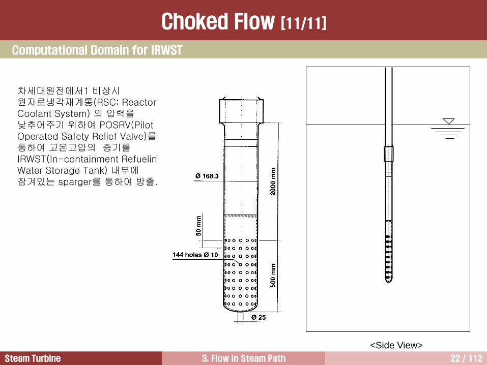
<Side View>
차세대원전에서1 비상시 원자로냉각재계통(RSC; Reactor Coolant System) 의 압력을 낮추어주기 위하여 POSRV(Pilot Operated Safety Relief Valve)를 통하여 고온고압의 증기를 IRWST(In-containment Refueling Water Storage Tank) 내부에 잠겨있는 sparger를 통하여 방출.
Computational Domain for IRWST
Choked Flow [11/11]

Steam Turbine 3. Flow in Steam Path 23 / 112
cc = 0.61
c = 0.98 cc = 1.00
c = 0.98
cc = 1.00
c = 0.82
Aj A0
cd = cc c
Aj = cc A0
Vactual = c Videal
m = Vactual Aj = ccc Videal A = cd Videal A
cd = discharge coefficient
(or flow coefficient)
cc = contraction coefficient
c = velocity coefficient
Flow of Fluids
(CRANE Co.)
Actual Flow
Fluid Flow

Steam Turbine 3. Flow in Steam Path 24 / 112
Steam Turbine Flow Model 2
Dimensionless Numbers 4
Fluid Dynamics 1
Thermodynamics and Fluid Dynamics for Steam Turbines 3
Impulse Turbine and Reaction Turbine 5
Stage Efficiency 6
Blade Profile Enhancement 7

Steam Turbine 3. Flow in Steam Path 25 / 112
Steam Turbine Flow Model
1
1
2
2
1
2
1
1
1
2
p
p
p
ppAcm d
1
1
2
2
1
21
1
2
p
p
p
pAacQ d
CV 1 2 3 4 5
SV = Stop Valves
CV = Control Valves
P = First Stage Shell Pressure
L-0 L-1
Con
de
nser
Stage Number
P
Steam
SV

Steam Turbine 3. Flow in Steam Path 26 / 112
The flow model is a series of orifices or nozzles in a pipe with a constant upstream pressure and downstream
pressure.
The pressure between any two of these orifices depends entirely on the quantity of steam and the nozzle
area following that point.
The first stage is represented as having four orifices to simulate a turbine with four control valves, while all the
other stages have only one orifice.
If all four control valves are opened, the flow will increase until an equilibrium condition is reached.
This steady state flow through each orifice in the model will be the same.
Therefore, the pressure upstream of each orifice will depend on the area of the downstream orifice.
As steam passes from throttle to the condenser, the areas of individual orifices are progressively larger.
Therefore, the pressure upstream of each stage is lower than the preceding stage.
A number of steam turbine stages can be classified into only three groups:
① The first stage or governing stage Variable flow area by control valve position
② The last stage (LSB) Flow choking is occurred
③ All the stages between Constant pressure ratio even during part load operation
In view of the specifics of the steam path design, all stages of a condensing steam turbine are divided into four groups,
① Governing stages
② Stages with high pressure and low volume discharge of steam (2D)
③ Intermediate stages with relatively low pressure and high volume discharge of steam (3D)
④ Last stages in the lowest-pressure range, characterized by a very high volume discharge.
Steam Turbine Flow Model

Steam Turbine 3. Flow in Steam Path 27 / 112
1st s
tag
e s
he
ll
2nd s
tag
e b
ow
l
500
1000
1500
2000
Thro
ttle
Pre
ssure
, psig
2500
2nd s
tag
e s
he
ll
3rd
sta
ge
bo
wl
3rd
sta
ge
sh
ell
4th s
tag
e b
ow
l
4th s
tag
e s
he
ll
5th s
tag
e b
ow
l
5th s
tag
e s
he
ll
6th s
tag
e b
ow
l
1800
1500
1250
1042
868
1200
Th
rott
le p
ress
2400
900
750
625 521
434
Factor
of 2 Factor
of 2
0
Steam Turbine Flow Model

Steam Turbine 3. Flow in Steam Path 28 / 112
For a throttle pressure of 2400 psig, the first stage
pressure with VWO would be 1800 psig and the
pressure downstream of the second stage would
be about 1500 psig. In this case, the pressure
ratio across the second stage is 1.2.
If throttle pressure decreases to 1200 psia, the
flow would decrease by a factor of 2 to 1. this
relationship holds true for all the stages until the
last stage. That is, the pressure ahead of the last
stage will decreases by a factor of 2 to 1.
All other stages, except HP first stage and LP last
stage, operate at a constant pressure ratio and
therefore a constant efficiency over the load range.
Velocity triangles for various
steam turbine loads
Intermediate Stage
Steam Turbine Flow Model

Steam Turbine 3. Flow in Steam Path 29 / 112
The governing stage has the unique characteristic of variable area.
As control valve opens, the area allowing throttle steam to flow through the turbine increase and produce
more power.
In addition, the change in flow changes the first stage discharge pressure, resulting in the pressure ratio
across the first stage.
Therefore, the first stage efficiency changes with control valve position.
At valves wide open the first stage is designed for the ideal ratio of wheel velocity and steam velocity.
As control valves close, the first stage efficiency decreases.
Partial
Arc Full
Arc
HP 1st Stage
Steam Turbine Flow Model

Steam Turbine 3. Flow in Steam Path 30 / 112
0 0.2 0.4 0.6 0.8 1.0
10
20
30
40
50
60
70
80
90
100
0
IP Turbine
LP Turbine
HP 2nd Stage to Cold Reheat
HP 1st Stage
Throttle Flow Ratio
Tu
rbin
e S
ectio
n E
ffic
ien
cy [%
]
HP 1st Stage
Steam Turbine Flow Model
Steam Turbine 3. Flow in Steam Path 31 / 112
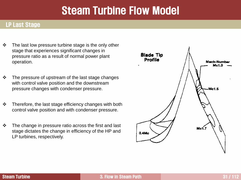
The last low pressure turbine stage is the only other
stage that experiences significant changes in
pressure ratio as a result of normal power plant
operation.
The pressure of upstream of the last stage changes
with control valve position and the downstream
pressure changes with condenser pressure.
Therefore, the last stage efficiency changes with both
control valve position and with condenser pressure.
The change in pressure ratio across the first and last
stage dictates the change in efficiency of the HP and
LP turbines, respectively.
LP Last Stage
Steam Turbine Flow Model

Steam Turbine 3. Flow in Steam Path 32 / 112
Stage Extract Bowl P Shell P Press Remarks
(psia) (psia) ratio
Throttle 3514.7
1 3409.3 2627.4 1.30
2 2122.2 1.24
3 1704.1 1.25
4 1355.9 1.26
5 1 1067.7 1.27
6 830.0 1.29
7 2 639.0 1.30 HP turbine outlet
IV 581.6
8 570.0 438.1 1.30
9 336.0 1.30
10 3 254.0 1.32
11 184.0 1.38
12 4 135.7 1.36 IP turbine outlet
X-over pipe
13 5 131.7 74.8 1.76 LP turbine inlet
14 40.5 1.85
15 6 20.5 1.96 Exceeding a critical PR
16 7 9.39 2.18 Exceeding a critical PR
17 8 4.07 2.31 Exceeding a critical PR
18 0.74 5.50 Connected to condenser
Stage Pressure Ratio [Sample]

Steam Turbine 3. Flow in Steam Path 33 / 112
0 1 2 3 4 5 6 7 8 9 10 11 12 13 14 15 16 17 18 19Stage number
0.0
0.5
1.0
1.5
2.0
2.5
3.0
3.5
4.0
4.5
5.0
5.5
6.0
6.5
7.0P
ressu
rera
tio
HP IP LP
Exceeding critical pressure ratio
Extraction stage : 5, 7, 10, 12, 13, 15, 16, 17
Stage Pressure Ratio [Sample]

Steam Turbine 3. Flow in Steam Path 34 / 112
Steam Turbine Flow Model
Discussion
Several LP turbine stages, 3rd to LSB, have higher than critical pressure ratio. Discuss the
following issues.
1) Possibility of choked flow
2) Flow area
3) Steam extraction
4) LSB in terms of degree of reaction
Critical pressure ratio
- superheated steam = 0.546 (=1.3)
- saturated steam = 0.577 (=1.135)
- air = 0.528 (=1.4)
(see K.C. Cotton, pp. 15)

Steam Turbine 3. Flow in Steam Path 35 / 112
Steam Turbine Flow Model 2
Dimensionless Numbers 4
Fluid Dynamics 1
Thermodynamics and Fluid Dynamics for Steam Turbines 3
Impulse Turbine and Reaction Turbine 5
Stage Efficiency 6
Blade Profile Enhancement 7

Steam Turbine 3. Flow in Steam Path 36 / 112
Flow Behavior in a Turbine Stage
Pressure E Kinetic E
Thermal E Thermal E Mechanical E
Nozzle Row Bucket Row
z
r
The flow behavior is investigated in a tangential plane.
Therefore, the flow velocity has two components, one is axial
component denoted by subscript z, and the other is
tangential component denoted by subscript implying a whirl
velocity.

Steam Turbine 3. Flow in Steam Path 37 / 112
Absolute vs. Relative Velocity
Fluid velocity is an important variable governing the
flow and energy transfer within a turbine.
The absolute velocity ( ) is the fluid velocity relative
to some stationary point and is usually parallel to the
nozzle (stationary blade).
When considering the flow across a rotating element
like a bucket, the relative velocity ( ) is important
and is usually parallel to the rotating element.
Vectorially, the relative velocity is defined as:
where is the tangential velocity
of the bucket.
ucw
u
w
c
[ Velocity Triangle in an Axial Turbine ]
u
u
c2
w2
2
2
w3
3 c3
p1
p2
p3
u
1
c1
3
Nozzle Row
Bucket Row

Steam Turbine 3. Flow in Steam Path 38 / 112
Velocity Triangle in a Turbine
Velocity Triangle at Root
Root
Tip
rRoot rTip
Nozzle Row Bucket Row
The absolute velocity increases from c1 to c2 across the nozzle.
The absolute velocity decreases from c2 to c3 across the bucket. This is because the kinetic energy entering
bucket is extracted by the bucket. Thus, bucket attains rotating power.
In the case of turbine, the convention chosen is that the angles are positive when measured in the direction of
rotation. Therefore, 2, 2 are positive; 3, 3 are negative.
c : absolute velocity of fluid
u : tangential velocity of blade
w : relative velocity of fluid to blade
u
u
c2
w2
2
2
w3
3 c3
p1
p2
p3
u
1
c1
3
Nozzle Row
Bucket Row

Steam Turbine 3. Flow in Steam Path 39 / 112
Velocity Triangle at Tip
Velocity Triangle in a Turbine
Root
Tip
rRoot rTip
Nozzle Row Bucket Row
u
u
c2
w2
w3
p1
p2
p3
u
1
c1
Nozzle Row
Bucket Row
2
2
3 c3
3

Steam Turbine 3. Flow in Steam Path 40 / 112
Expansion Lines
A nozzle is used to provide partial
expansion of the gas as well as to
guide the flow smoothly into a
bucket.
If the flow is isentropic in the nozzle,
condition 2s is achieved after
passing through the nozzle.
Practically, however, nozzle
expansion occurs along curve 1-2
because of losses occurred in the
nozzle path.
Change in stagnation pressure
(po,1po,2) is due to the losses,
because there is no work extraction
from the fluid inside the nozzles.
The process along 2-3 represents
the expansion through bucket.
If the flow is isentropic only in the
bucket, condition o,3s or 3s is
achieved.
p3
po3
1
o,3ss
p2
o,1
p1
po,2 po,1
1/2c12
2
1/2c22
h
s
1/2c32
3ss
2s
o,3s
3s
o,3
3
o,2
u
u
c2
w2
2
2
w3
3
c3
p1
p2
p3
u
1
c1
3
Nozzle Row
Bucket Row
[ Expansion Line in a Turbine Stage ]

Steam Turbine 3. Flow in Steam Path 41 / 112
Turbine Efficiencies
Total-to-static Efficiency Total-to-total Efficiency
• In many turbines (especially steam turbines), the
kinetic energy at the exit (c32/2) should be as small
as possible, because this represents aerodynamic
loss.
• Therefore, the design philosophy is to achieve as
low a velocity at the exit as possible. For this reason,
active length of LSB of steam turbines is very long.
• In such situations, a total-to-static efficiency is used.
• In most aeronautical applications gas turbines, the
exhaust energy is utilized for thrust generation.
Therefore, the exhaust energy is used to produce
useful power.
• Therefore, a more appropriate definition to
represent the performance of these turbines is the
total-to-total efficiency .
• The total-to-total efficiency is also defined as
isentropic efficiency.
• For a multistage turbine, total-to-total efficiency
should be used because the kinetic energy at the
exit of a stage (except the last stage) is not lost.
sso
oo
ssssossoo
oo
tshh
hh
hhhh
hh
31,
3,1,
33,3,1,
3,1,
ssoo
oo
tthh
hh
3,1,
3,1,

Steam Turbine 3. Flow in Steam Path 42 / 112
Notation for Flow in a Bucket Row
u
w3
3
c3
c2
w2
2 2
3
N B
w,3
c,2 c,3
w,2
dc = (c,2 c,3)
u
c: absolute velocities (velocities in the reference
frame of the nozzles)
w: relative velocities (velocities relative to moving
surface, the buckets)
u: tangential velocities of blades (in the positive
direction)
2, 2 are positive, and 3, 3 are negative.
r2 r3
w2 or c2 w3 or c3
Bucket
Row
u
u
c2
w2
2
2
w3
3 c3
p1
p2
p3
u
1
c1
3
Nozzle Row
Bucket Row
Euler Equation [1/7]

Steam Turbine 3. Flow in Steam Path 43 / 112
Euler Equation [2/7]
The change of momentum between the flow entering and leaving the bucket can be used to calculate the
force acting on the bucket.
There are three principal components of this force, axial, radial, and tangential.
The axial and radial components are important for the design of bearings and for the analysis of vibration
excitations, etc.
But, these two components cannot contribute to the work transfer between the working fluid and the bucket.
Only the tangential component of the force can produce a change in enthalpy through a work transfer.
Tangential force on rotor from entering fluid =
Work bucket = force length =
Power on bucket per unit time = work on rotor / time =
Net power on bucket,
Therefore, Euler’s equation can be derived.
(e.1)
Turbine has a positive work out, however, a pump, fan, and compressor will have negative work out.
2,cm
22, rcm
22, rcm
3,32,233,22,23 cucumrcrcmW
3,32,22323 / cucumWw
22, cc
Euler equation

Steam Turbine 3. Flow in Steam Path 44 / 112
Euler Equation [3/7]
For an adiabatic bucket row in the absence of external torques, or large changes in elevation, the first law of
thermodynamics gives,
(e.3)
The first law of thermodynamics is,
(e.2)
3,2,23 oob hhww
2323
2
2
2
3223323232
1wzzgccppuuq
2323
2
2
2
323232
1wzzgcchhq
23232,3,23 wzzghhq oo
232,3,23 whhq oo
Therefore, following relationship can be obtained from Euler equation,
or (e.4)
It is clear that the stagnation enthalpy and pressure drop in a turbine are directly proportional to the change
in tangential velocity and blade speed. This is the most useful single relation in turbine design.
In the preliminary design of axial flow machines, the change of radius of the mean flow can often be ignored,
so that a more restricted version of Euler’s equation becomes
(e.5)
θucddho
θdcudho
c2
c3 q
w z2
z3
2
3
3,32,23,2,23 cucuhhww oob

Steam Turbine 3. Flow in Steam Path 45 / 112
Euler Equation [4/7]
Pressure and Temperature Drop in a Bucket Row
2,23,32,3,2,3, cucuTTchh oopoo
11
1
2,
3,
2,
2,
3,
2,2,3,
o
o
op
o
o
opoop
pTc
T
TTchh
32222,3,2,23,3 tantancos ucccucucu
1
32
2,
22
2,
3,tantan
cos1
opo
o
Tc
uc
p
p
For simple diagram having constant u from stage inlet to outlet,
32
2,
22
2,
3,tantan
cos1
opo
o
Tc
uc
T
T
2,23,32,3,23 cucuhhww oob
1
322
2,
3,tantan
11
a
uv
p
pz
o
o
322
2,
3,tantan
11
a
uv
T
Tz
o
o
Steam Turbine 3. Flow in Steam Path 46 / 112
1
322
2,
3,tantan
11
a
uv
p
pz
o
o
322
2,
3,tantan
11
a
uv
T
Tz
o
o
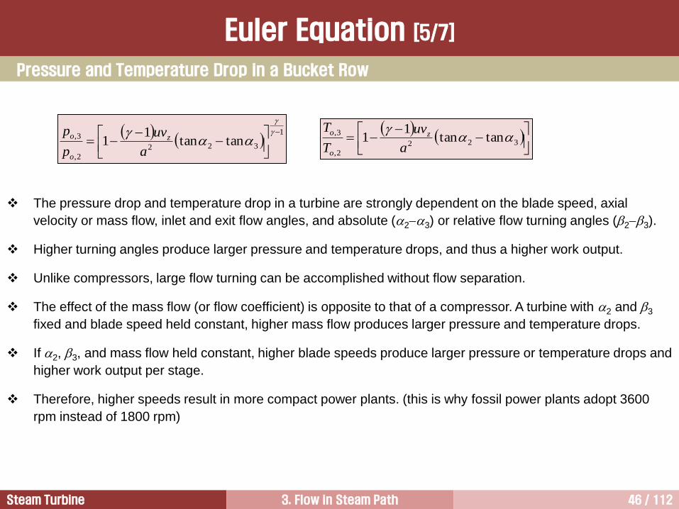
The pressure drop and temperature drop in a turbine are strongly dependent on the blade speed, axial
velocity or mass flow, inlet and exit flow angles, and absolute (23) or relative flow turning angles (23).
Higher turning angles produce larger pressure and temperature drops, and thus a higher work output.
Unlike compressors, large flow turning can be accomplished without flow separation.
The effect of the mass flow (or flow coefficient) is opposite to that of a compressor. A turbine with 2 and 3
fixed and blade speed held constant, higher mass flow produces larger pressure and temperature drops.
If 2, 3, and mass flow held constant, higher blade speeds produce larger pressure or temperature drops and
higher work output per stage.
Therefore, higher speeds result in more compact power plants. (this is why fossil power plants adopt 3600
rpm instead of 1800 rpm)
Pressure and Temperature Drop in a Bucket Row
Euler Equation [5/7]

Steam Turbine 3. Flow in Steam Path 47 / 112
[Exercise 3.1] Use of the Euler’s equation
What is the power output (kW) of the first stage of an axial flow steam turbine which takes 600 kg/s of
steam at 600C and 250 bar stagnation conditions? After passing through the nozzle, the flow leaves
nozzle at a direction 70 degrees from that of axial, at a velocity of 500 m/s, as given in figure 1, and
discharges it from the bucket (rotor) without swirl (c,3 = 0). The pitch diameter of the bucket is 1 m, and
the shaft speed is 3600 rpm. The turbine has an isentropic stagnation-to-stagnation stage efficiency of
90 percent.
Figure 1
Euler Equation [6/7]
2=70

Steam Turbine 3. Flow in Steam Path 48 / 112
Euler Equation [7/7]
[Solution]
Power output of the stage can be obtained
The first law of thermodynamics is as follows,
The turbine can be treated as adiabatic. Therefore,
From the Euler equation,
From the given conditions,
Therefore,
smrn
u /5.18860
22
smcc /470sin 222,
23,2, /566,88 smhh oo
kWs
m
s
kghhmhmW oo 140,5388566600
2
2
3,2,23
MWWW turbinenet 8.4723,23
232,3,23 whhq oo
2,23,32,23,2, cucucuhh oo
2,3,23 oo hhw 3,2,23 oo hhmW
3,2,23 oo hhmhmW

Steam Turbine 3. Flow in Steam Path 49 / 112
Steam Turbine Flow Model 2
Dimensionless Numbers 4
Fluid Dynamics 1
Thermodynamics and Fluid Dynamics for Steam Turbines 3
Impulse Turbine and Reaction Turbine 5
Stage Efficiency 6
Blade Profile Enhancement 7

Steam Turbine 3. Flow in Steam Path 50 / 112
By means of dimensional analysis, a group of variables representing some physical state is reduced into a
small number of dimensionless groups.
This enables a unique representation of certain classes of machines based on pressure rise (or drop) and
mass flow. Most importantly, it enables reduction of laboratory testing effort by reducing the number of
variables.
Specifically, the following can be accomplished:
1) Prediction of a prototype performance from tests conducted on a scaled model (similitude).
2) Unique representation of the performance (e.g., Mach number, Reynolds number effect).
3) Determination of a best machine on the basis of efficiency for specific head, speed, and flow rate.
Most important dimensionless numbers in axial turbines are degree of reaction, loading coefficient, flow
coefficient, etc.
Generals

Steam Turbine 3. Flow in Steam Path 51 / 112
The most important performance variable is the work done on the fluid, or delivered by the machines. Its
dimensionless form is the loading coefficient, which is also called as work coefficient.
That is, the loading coefficient reflects the pressure/temperature drop across a turbine.
For an adiabatic stage, the loading coefficient is defined by the ratio of specific stage work input to the square
of mean bucket speed, that is,
where wb is the isentropic work done at bucket row.
For simple diagram having constant u from stage inlet to outlet,
The loading coefficient is positive for turbines, and negative for compressors and pumps.
Loading Coefficient [1/2]
2
3,32,2
2
3,2,
2 u
cucu
u
hh
u
w oob
32
3,2,tantan
u
v
u
ccz

Steam Turbine 3. Flow in Steam Path 52 / 112
Loading Coefficient [2/2]
(a) high-work turbine
( = 2.0, = 0.5, = 0.5) ( = 1.0, = 0.5, = 0.5) ( = 0.5, = 0.5, = 0.5)
(b) medium-work turbine (c) low-work turbine
( = work coefficient, = flow coefficient, = degree of reaction)
In turbines having the value of 1.5 are called as “highly-loaded” or “high-work” turbines (or turbine
sections). Values of 1.0 mean “low-work” or “lightly-loaded” turbine stages.
Normally, last stage blades of steam turbines have very high loadings at the hub, and light loadings at the tip.
The value of the loading coefficient for an impulse turbine with a maximum loading coefficient is two when the
exit swirl is zero. In a 50% reaction turbine with a maximum loading coefficient is one.
(a) 0% reaction velocity diagram
u
c2 w3
w2
c3
c,2 = 2u
w3
w2
c2
u
c3
c,2 = u
(b) 50% reaction velocity diagram

Steam Turbine 3. Flow in Steam Path 53 / 112
The flow coefficient reflects the effect of the mass flow as well as blade speed.
The flow coefficient is defined the ratio of the axial velocity entering to the mean bucket speed, that is,
In a simple velocity diagram, the flow coefficient is constant.
The flow coefficient can be different at rotor inlet and at rotor outlet where both cz and u vary through the
stage.
It also varies with radius.
The relationship between loading coefficient and flow coefficient is
u
vz
Flow Coefficient
32 tantan

Steam Turbine 3. Flow in Steam Path 54 / 112
Smith Chart
A useful investigation of turbine performance
characteristics was compiled by Smith with more
than 100 sets of data from 33 turbines.
Smith found that the efficiency of a turbine depends
strongly on the loading coefficient and the flow
coefficient.
The loading coefficient influences the pressure
gradient in the passage, and this increases the
losses.
The flow coefficient is a direct measure of the mass
flow, for a given speed and machine size.
Higher flow coefficient, and hence higher mass flow,
results in a higher pressure drop, and the
corresponding losses also increase.
Therefore, the highest efficiencies occur at low loading and low flow coefficient.
As well as being an excellent comparator for different design options, the chart may be used to give
preliminary judgment on the efficiency attainable for a given design.
The chart gives the highest efficiency. This means that it was produced under the assumption that the turbine
is designed with large blades, and zero tip clearance.
In a practical design which has all the above merits, the highest efficiency attainable would be 95%.
When the lower technology level blades are employed, three points may be reduced from the values obtained
from the chart.

Steam Turbine 3. Flow in Steam Path 55 / 112
Degree of Reaction [1/10]
The degree of reaction in the turbine is defined as,
In the nozzle path, the first law of thermodynamics is,
(1)
In the nozzle, adiabatic process occurs, and no work produces.
Therefore, equation (1) becomes,
(2)
From the first law of thermodynamics,
(3)
The following relationships are valid is a turbine stage.
; adiabatic process
; for a normal stage
; no work at nozzle row
Thus,
(4)
2
1
2
221 5.0 cchh
12
2
1
2
21212 5.0 wcchhq
31
21
31
32 1hh
hh
hh
hh
static enthalpy drop in the bucket
static enthalpy drop in the stage
= 100 (%)
13
2
1
2
31313 5.0 wcchhq
013 q
31 cc
23133,1,
2
33,
2
11,312
1
2
1wwhhchchhh oooo
23231213 wwww
p3
po3
1
o,3ss
1/2c12
p2
o,1
p1
po,2 po,1
1/2c12
2
1/2c22
h
s
1/2c32
3ss
2s
o,3s
3s
o,3
3
o,2
[ Expansion Line in a Turbine Stage ]

Steam Turbine 3. Flow in Steam Path 56 / 112
Degree of Reaction [2/10]
Using Euler equation,
(5)
Input the equations (2) and (5) into (1) gives,
From the velocity triangle,
For a simple velocity triangle,
Therefore, the degree of reaction becomes,
For a simple velocity diagram having constant u from stage inlet
to outlet.,
(6)
3,32,22331 cucuwhh
3,32,2
2
3
2
2
21
cucu
cc
2
2,
2
2,
2
2 cvc z
2
3,
2
3,
2
3 cvc z
3,32,2
2
3,
2
2,
21
cucu
cc
3,2, zz vv
32 uuu 32
3,2,tantan1
21
u
v
u
ccz
[ Velocity Triangle in a Turbine Stage ]
u
u
c2
w2
2
2
w3
3 c3
p1
p2
p3
u
1
c1
3
Nozzle Row
Bucket Row

Steam Turbine 3. Flow in Steam Path 57 / 112
Degree of Reaction [3/10]
Equation (6) becomes,
(7)
From Euler equation,
(8)
Divide equation (8) by u2 gives,
( ) (9)
From equation (7) and (9), an important result is obtained.
(10)
From equation (9) and (10), the unknown angles of the absolute velocity can be obtained.
(11)
Turbomachinery design initiated by experienced designers through the choice of the flow and loading
coefficients and the degree of reaction and then determine the flow angles using eq. (11). These are true
only for a normal stage. If the axial velocity does not remain constant, the proper equations need to be
redeveloped from the fundamental concepts.
32
32 tantan2
12
tantan1
u
vz
323,2, tantan zb ucccuw
u
cz2u
ws 32 tantan
13 tan12tan12
2/1tan 3
2/1tan 2
1tan2 2

Steam Turbine 3. Flow in Steam Path 58 / 112
Similar expressions can be developed for the flow angles
of the relative velocity.
The Euler equation can be written as
Divide equation (8) by u2 gives,
Since the stagnation enthalpy of the relative motion is
constant across the bucket. Thus,
Therefore, the unknown angles of the relative velocity can
be obtained.
(12)
323,2, tantan zs uvwwuw
2
2
3
222
2
2
332 tantan2
1
2
1 zvwwhh
31
32
hh
hh
32 tantan
u
w3
3
c3
c2
w2
2 2
3
N B
w,3
c,2 c,3
w,2
dc = (c,2 c,3)
u
Degree of Reaction [4/10]
32 tantan2
2/tan 3
2/tan 2

Steam Turbine 3. Flow in Steam Path 59 / 112
Degree of Reaction [5/10]
It shows that the loading increases as the reaction decreases.
A small reaction means that the pressure drop across the bucket
is small, but the large loading is the result of a large deflection.
In the nozzle, the flow leaves at high speed at large angle 2.
The high kinetic energy obtained this way becomes available for
doing work on the buckets.
The flow is then deflected back toward the axis and beyond to a
negative value of 3, so that the last term in equation (10) is
positive. (3 = 1 in most turbine stages)
Thus, for a fixed reaction, an increase in the absolute value of 3,
obtained by increasing it in the opposite direction of u, leads to a
large deflection and a large value of loading coefficient.
Thus, a fairly low value of reaction and high turning gives heavily
loaded blades and a compact design.
(10)
u
u
c2
w2
2
2
w3
3 c3
p1
p2
p3
u
1
c1
3
Nozzle Row
Bucket Row
13 tan12tan12
1tan2 2

Steam Turbine 3. Flow in Steam Path 60 / 112
(a) 0% reaction velocity diagram
u
c2 w3
w2
c3
c,2 = 2u
w3
w2
c2
u
c3
c,2 = u
c2
w3
u
w2 c3
c,2 c,3
(b) 50% reaction velocity diagram
(c) 100% reaction velocity diagram
Degree of Reaction [6/10]

Steam Turbine 3. Flow in Steam Path 61 / 112
0% Reaction 50% Reaction
• A zero reaction turbine is called an impulse turbine
because there is no expansion or acceleration of
the flow through the rotor blades, and the rotor
torque comes wholly from the impulse of the nozzle
stream.
• With no pressure drop across the bucket row,
pressure seals are not required.
• A frequently used impulse diagram has axial stage
entry and exit flows and the reasonably high loading
coefficient of 2.0.
• In 50% reaction velocity diagrams, the bisector of
the line joining the apexes of the absolute and
relative velocity triangles crosses u in the middle,
which is why the diagrams become symmetric.
• Such diagrams are frequently favored for turbines
because they have accelerating flow to an equal
extent in nozzle and bucket passages, which leads
to lower losses.
• The rectangular turbine stage diagram shown in
above has the additional advantage of having axial
flow at stage inlet and outlet. Also tests show this
gives the highest efficiency for turbine stages.
u
c2 w3
w2
c3
c,2 = 2u
w3
w2
c2
u
c3
c,2 = u
Degree of Reaction [7/10]

Steam Turbine 3. Flow in Steam Path 62 / 112
0% Reaction Stage
Degree of Reaction [8/10]
u
u
c2
w2
2
2
w3 3
c3
p1
p2
p3
u
c1
Nozzle Row
Bucket Row
All of the static enthalpy drops across the nozzle in a 0%
reaction stage. For such a stage, from eq. (12),
or
It can be assumed that the axial velocity is constant at the
inlet and exit of the stage. In this case,
w2 = w3
If the flow angles are equal to the blade angles, then the
bucket has a symmetric shape.
The blades having low reaction are heavily loaded.
For a normal stage with axial entry and with degree of
reaction of 0, the relation reduces to
For an impulse stage, the flow angles for absolute and
relative velocity are reduced to
32 tantan 32
3tan12
2
u
w3 3 c3
c2
w2
2 2
N B
w,3
c,2
w,2
dc = (c,2 c,3)
u
2/1tan 3
2/1tan 2
2tan 3
2tan 2

Steam Turbine 3. Flow in Steam Path 63 / 112
Degree of Reaction [9/10]
50% Reaction Stage [1/2]
3
3
u
w3 c2
c3
2
w2
2
N
w,3
c,3 c,2
w,2
dc = (c,2 c,3)
B
A 50% reaction stage has equal static enthalpy drops across the
nozzle and bucket. For such a stage
In order to get a high efficiency, the flow angle at the inlet is kept
only slightly negative, but if some of the efficiency is sacrificed to
achieve higher performance, the inlet flow angle may reach 1 =
45.
For such a stage, a flow coefficient may have a value of = 0.75,
which gives = 2.5.
For a 50% reaction stage, the flow angles for absolute and relative
velocity are reduced to
From these it can be seen that
Therefore, the velocity triangles formed at the inlet and exit of the
bucket are symmetrical each other. Thus,
1tan2tan21 23
2
1tan 3
2
1tan 2
2
1tan 3
2
1tan 2
32 tantan 23 tantan
32 wc 32 cw [ Velocity Triangle ]
w2
c2
u
c1 1
2
2
Nozzle Row
u
Bucket Row
c3
w3
u 3
3
p1
p2
p3

Steam Turbine 3. Flow in Steam Path 64 / 112
1tan2tan21 23
50% Reaction Stage [2/2]
Degree of Reaction [10/10]
The stage loading coefficient for 50% reaction stage is,
The figure gives the design and off-design performance of
50% reaction stage, based on above equation.
It is clear from the figure that increases linearly with for a
given 2.
The loading coefficient increases with 2 for a given flow
coefficient.
The present trend in the design of the nozzle is to use as high
an 2 as possible. But it should be realized that increasing 2
increases w2 for a given blade speed, and thus the flow is
likely to reach supersonic speeds and limit the mass flow.
Therefore, the designer has to vary 2, u, , and vz (or ) to
get an optimum design for a given turbine inlet temperature.
The curves in this figure are for ideal conditions. That is,
viscous losses, shock losses, or three-dimensional effects are
not included.
0.0 0.2 0.4 0.6 0.8 1.0
2.5
2.0
1.5
1.0
0.5
0.0
-0.5
-1.0
Flow Coefficient
Sta
ge
Lo
ad
ing C
oe
ffic
ient
2 3=5 10
20
40
60
80
100 120
140
[ 50% Reaction Stage ]

Steam Turbine 3. Flow in Steam Path 65 / 112
Steam Turbine Flow Model 2
Dimensionless Numbers 4
Fluid Dynamics 1
Thermodynamics and Fluid Dynamics for Steam Turbines 3
Impulse Turbine and Reaction Turbine 5
Stage Efficiency 6
Blade Profile Enhancement 7

Steam Turbine 3. Flow in Steam Path 66 / 112
유체유동에 의해 발생하는 힘
2
1
Axial
Tangential
1Vm
2211 sinsin VVm
2Vm
1V
2V
터빈 동력생산 원리

Steam Turbine 3. Flow in Steam Path 67 / 112
NACA 4412
2
222
2
1112
1
2
1VpVppo
Velocity Distribution around an Airfoil
Flow Behaviors around an Airfoil [1/3]
Pressure distribution
Velocity distribution

Steam Turbine 3. Flow in Steam Path 68 / 112
pdALift
Lift
Pressure surface
Suction surface
x
p
(AOA = 5 deg.)
There is an angle of attack that produces
the optimum lift force. If this angle is
exceeded, the airfoil stalls and the drag
force increases rapidly.
Lift
Flow Behaviors around an Airfoil [2/3]

Steam Turbine 3. Flow in Steam Path 69 / 112
c1
2 c2
P S S P
p2 p1 p
po
½ c12
½ c22
p2
1
b
Direction
of rotation
P: Pressure surface
S: Suction surface
Lifting Force Acting on a Turbine Blade
Flow Behaviors around an Airfoil [3/3]

Steam Turbine 3. Flow in Steam Path 70 / 112
Degree of Reaction
%10031
32
hh
hh
%10031
32
TT
TT
%10031
32
pp
pp
dpdhq
Thermodynamic process occurred in compressor and turbine is adiabatic process.
And ignoring density changes.
dpdh
static enthalpy drop in the bucket
static enthalpy drop in the stage
= 100 (%)

Steam Turbine 3. Flow in Steam Path 71 / 112
Impulse Turbine
The pressure and velocity of the gases passing through the
bucket of the impulse turbine remain essentially the same,
and the only change thing is the direction of flow.
Therefore, the degree of reaction of the impulse turbine is
zero.
The turbine absorbs the energy by the change of the direction
of the high velocity gases.
[ Impulse Turbine, = 0% ]
Vj U
Vj U Bucket
F
U
Nozzle Row
Bucket Row
[ LSB (GE) ]

Steam Turbine 3. Flow in Steam Path 72 / 112
Reaction Turbine
Nozzle Row
Bucket Row
A reaction turbine changes the velocity and pressure of the gases.
The cross-sectional area formed between two adjacent buckets
decreases. Thus, gas velocity increases and pressure decreases
during passing through the passage.
Therefore, reaction turbine extracts energy by the reaction force
produced by the acceleration of the flow through the convergent
duct.
The degree of reaction of the reaction turbine is 50%.
[ Reaction Turbine , = 50% ]
Vi
Convergent
nozzle
Ve
U
F
[ LSB (Siemens) ]

Steam Turbine 3. Flow in Steam Path 73 / 112
Evolution of Turbine Blade
Siemens GEC AEI Rateau SCAM BBC Sulzer AEG
GE USA IMPULSE
Siemens-KWU D REACTION
W/H USA REACTION
BBC CH REACTION
Alsthom F IMPULSE
GEC UK IMPULSE 1970
2000 GE USA IMPULSE
Siemens-Westinghouse D REACTION
ABB-Alsthom F REACTION
MHI J REACTION
Ansaldo
Toshiba
Doosan
Hitachi
1998
N. Piignone
BHEL
Parsons
Fuji
MHI
ABB GEC-Alsthom
1989 1987
CEM
LMZ
Zamech
ASEA STAL
F. Tosi
De Pretto
1999

Steam Turbine 3. Flow in Steam Path 74 / 112
Impulse vs. Reaction
The impulse turbine has its entire enthalpy drop in
the nozzle. Therefore, it has a very high velocity
entering the bucket.
Ideally there is no change in the magnitude of the
relative velocity w between inlet and exit (which
are denoted by subscripts 2 and 3, respectively).
The large inlet velocity c2 has been reduced to a
small absolute exit velocity c3, which ideally is in
the axial direction.
u : tangential velocity of blade
w : velocity of fluid relative to blade
c : absolute velocity of fluid
The reaction turbine divides its enthalpy drop in both
nozzle and bucket.
Therefore, velocities are accelerated when the steam is
passing through both the nozzle and the bucket.
Impulse Turbine Reaction Turbine
u
u
c2
w2
2
2
w3
3 c3
p1
p2
p3
u
1
c1
3
Nozzle Row
Bucket Row
w2
c2
u
c1 1
2
2
Nozzle Row
u
Bucket Row
c3
w3
u 3
3
p1
p2
p3

Steam Turbine 3. Flow in Steam Path 75 / 112
Velocity Diagram
Impulse Turbine Reaction Turbine
c1
u
2
c2
p1
p2
u
w2
w2
Nozzle Bucket
A1
A2N 2
A2B A3B
w3
u
c3
3 = 0
A2N A1
A2B = A3B
|2| = |3|
|w2| = |w3|
c2 4c1
p3
T1
T2 T3
c2
c1
w2
w3
3
c1
U
2
c2
p1
p2
u
w2 w2
Nozzle Bucket
A1
A2N 3
w3
c3
3 = 0
p3 T1
T2
T3
c2
A2B
A3B
u
w3
2 = 0
A2N A1
A3B A2B
|c2| |c1|
|w3| |w2|
c2 2c1
c1
w2

Steam Turbine 3. Flow in Steam Path 76 / 112
Multistage Impulse Turbine
Pressure
Absolute
Velocity
Distance through Turbine
Nozzle Bucket Nozzle Bucket Nozzle Bucket
The impulse turbine has its
entire enthalpy drop in the
nozzle, therefore, it has a very
high velocity entering the
bucket.

Steam Turbine 3. Flow in Steam Path 77 / 112
Multistage Reaction Turbine
Pressure
Absolute
Velocity
Distance through Turbine
Nozzle Bucket Nozzle Bucket Nozzle Bucket
half of impulse turbine

Steam Turbine 3. Flow in Steam Path 78 / 112
Question
1. Compare the impulse and reaction turbine in terms of SPE.
2. Compare the impulse and reaction turbine in terms of profile loss.
3. Suggest the equation to calculate the thrust produced in a stage.
4. Which type of turbine requires bigger thrust bearings?
5. Single stage supersonic impulse turbine is shown in the figure.
1) Discuss the shape of nozzle path.
2) What is the purpose of the increasing nozzle exiting velocity up to supersonic velocity?
Single Stage Supersonic Impulse Turbine
31 ppdlT
T = Thrust
d = mean diameter of blade row
l = active length of blade
p1 = pressure at the inlet of stage
p3 = pressure at the exit of stage
= degree of reaction at the mean dia.

Steam Turbine 3. Flow in Steam Path 79 / 112
Comparison of Velocity Triangle
F = mV = m(c2sin2 + c3sin3)
= mc2sin2
P = mc2sin2u
F = mV = m(c2sin2 + c3sin3)
= mc2sin2
P = mc2sin2u
Impulse Turbine Reaction Turbine
2
2
3
3
w3
w2
c2
u
u
c3
w2sin2
w3sin3
u u
2u = c2sin2
2
3
w3
w2
c2
u
u
c3
u = c2sin2
w3sin3
u u

Steam Turbine 3. Flow in Steam Path 80 / 112
Comparison of the Number of Turbine Stages
Impulse Reaction
Let us consider a nozzle row only. This is
because there is no heat addition
and work out as well.
Neglecting inlet velocity,
Assume,
• h across fixed blades in reaction turbine is only 1/4 that of impulse turbine.
• Reaction turbines, however, have an additional equivalent h across the moving blades.
• Therefore, total h in reaction turbine is a half of impulse turbine.
• This means that reaction turbine needs twice number of stages to generate same output.
outin wPEKEFEuq outin wchchq 2
22
2
112
1
2
1
2
1
2
2212
1
2
1cchh
2
221 ch 2
221 ch
o902
uc 22 uc 2
22uh 25.0 uh

Steam Turbine 3. Flow in Steam Path 81 / 112
Smaller Rotor and Wheel Diameter Single Flow Control Stage
Design Change of HP Turbine - GE

Steam Turbine 3. Flow in Steam Path 82 / 112
The length of the rotor shaft is almost same. The reasons for this are
1) Pressure drop across the nozzle path in the impulse turbine is double of the reaction turbine. Therefore,
the diaphragms of the impulse turbine should be stronger than those of the reaction turbine.
2) Turbine buckets of the impulse turbine have to work twice of the reaction turbine. Thus, turbine buckets
should be much stronger than those of the reaction turbine.
Another important thing is that the active length of the reaction bucket is longer than that of impulse bucket.
The longer active length of buckets, the higher the turbine efficiency.
Design Change of HP Turbine - GE

Steam Turbine 3. Flow in Steam Path 83 / 112
Newly Designed HP Turbine [GE]
ALSTOM HP Turbine

Steam Turbine 3. Flow in Steam Path 84 / 112
Steam Turbines for CCPP Application GE
D-11 for Combined Cycle Units
207D-17 Steam Turbine

Steam Turbine 3. Flow in Steam Path 85 / 112
Reaction Type HP Turbine – 200 MW Steam
Turbine for the K-Power. (Hitachi)
Number of Turbine Stages
Impulse Type Steam Turbine
The number of stages of reaction turbine is twice of impulse turbine.
1) Suggest the method that make the number of stages of reaction turbine is equal to that of
impulse turbine.
2) The answer of the above question is not applied in the practical reaction turbine. Discuss the
reason for that.

Steam Turbine 3. Flow in Steam Path 86 / 112
Velocity Diagram
Reaction Stage
u = 0.65v0
c3 = 0.24v0
w2 = 0.24v0
u = 0.65v0
p1
p2
p3
Steam Flow
20
Impulse Stage
p1
u = 0.5v0
p2
u = 0.5V0
c3 = 0.23v0 p3
Steam Flow
13

Steam Turbine 3. Flow in Steam Path 87 / 112
The velocity increase about four times in
the nozzle and its direction changes from
axial to about 77 off axial.
Vo is the velocity of stream expanded from
the pressure upstream of a stage to the
downstream pressure without loss.
In a pure impulse stage the optimum u/c2 is
0.5.
The velocity leaving the stage should be
close to axial to minimize the stage leaving
loss.
Impulse Stage
In a 50% reaction stage, half of the
pressure drop is across the nozzle and
another half is across the bucket.
The flow turning in the nozzle of reaction
stage is smaller than that of impulse stage.
The inlet velocity of bucket in the reaction
stage is smaller than that in the impulse
stage.
The lower velocity results in lower friction
loss and lower erosion.
The shape of nozzle and bucket is same in
a 50% reaction stage.
Reaction Stage
Velocity Diagram

Steam Turbine 3. Flow in Steam Path 88 / 112
Comparison of Leakage
Impulse Reaction
Bucket
Tip
Diaphragm
Root
cylindrical
drum type
rotor
disc wheels
shrunk on to a
rotor shaft
Steam Turbine 3. Flow in Steam Path 89 / 112
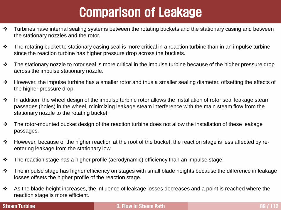
Turbines have internal sealing systems between the rotating buckets and the stationary casing and between
the stationary nozzles and the rotor.
The rotating bucket to stationary casing seal is more critical in a reaction turbine than in an impulse turbine
since the reaction turbine has higher pressure drop across the buckets.
The stationary nozzle to rotor seal is more critical in the impulse turbine because of the higher pressure drop
across the impulse stationary nozzle.
However, the impulse turbine has a smaller rotor and thus a smaller sealing diameter, offsetting the effects of
the higher pressure drop.
In addition, the wheel design of the impulse turbine rotor allows the installation of rotor seal leakage steam
passages (holes) in the wheel, minimizing leakage steam interference with the main steam flow from the
stationary nozzle to the rotating bucket.
The rotor-mounted bucket design of the reaction turbine does not allow the installation of these leakage
passages.
However, because of the higher reaction at the root of the bucket, the reaction stage is less affected by re-
entering leakage from the stationary low.
The reaction stage has a higher profile (aerodynamic) efficiency than an impulse stage.
The impulse stage has higher efficiency on stages with small blade heights because the difference in leakage
losses offsets the higher profile of the reaction stage.
As the blade height increases, the influence of leakage losses decreases and a point is reached where the
reaction stage is more efficient.
Comparison of Leakage

Steam Turbine 3. Flow in Steam Path 90 / 112
• Velocity and pressure distribution along radial direction are uniform at the inlet and outlet of the stage.
• Velocity decreases along radial direction between nozzle and bucket.
• Pressure increases along radial direction between nozzle and bucket.
Radial Variation of Pressure and Absolute Velocity
Impulse-Reaction Turbine [1/6]
c1 c3
p1 p2 p3
c2
w2R
w2M
w2T
uR
uM
uT
c2R
c2M
c2T

Steam Turbine 3. Flow in Steam Path 91 / 112
노즐의 역할은 작동유체의 압력에너지를 운동에너지로 변환시키는 것이다. 따라서 노즐을 통과한 작동유체의 속도는 크게 증가한다. 그러나 노즐 출구에서의 축방향 속도는 노즐 입구에서와 동일하기 때문에 접선방향 속도만 크게 증가한다. 이로 인해 노즐 출구를 빠져 나온 작동유체는 큰 선회유동으로 인해 원심력이 발생하여 유체는 버켓 팁(tip) 쪽으로 집중되는 경향을 가진다.
유동이 버켓 팁 쪽으로 편중되면 버켓과 케이싱 사이에서 누설손실이 증가하며, 버켓 팁 근처에서 이차유동손실이 증가할 뿐만 아니라 반경방향을 따라서 버켓에서 생산하는 동력도 균일하지 못하게 된다.
이런 문제를 해결하기 위해서 버켓 팁 입구 쪽의 압력을 루트(root, or hub) 입구 쪽 압력보다 높게 유지시킨다. 이 경우 버켓 입구의 팁부분 압력이 루트부에 비해 높기 때문에 팁 쪽에서 루트 방향으로 진행하는 유동이 형성된다.
즉 버켓 팁 쪽에 형성되는 높은 압력으로 인해 루트 쪽으로 진행하려는 힘과 원심력에 의해 루트에서 팁 쪽으로 진행하려는 두 힘은 서로 방향이 반대이기 때문에 두 힘의 크기를 비슷하게 해주면 노즐과 버켓 사이에서 유동은 축방향으로 평행하게 흘러가며, 앞서 언급된 제반 문제점들이 사라지게 된다.
따라서 노즐과 버켓 사이에 형성되는 유동의 특징은 반경방향을 따라서 속도는 줄어들고, 압력은 증가한다.
한편, 축류형 다단 터빈은 버켓 입구에서 뿐만이 아니라 출구에서도 압력과 속도는 반경방향을 따라서 일정하게 유지되어야 한다.
따라서 버켓은 루트에서 팁 쪽으로 가면서 반동도가 증가하기 때문에 버켓 루트는 충동형, 팁은 반동형으로 설계한다.
이런 이유 때문에 터빈 버켓은 하나의 블레이드에 충동형과 반동형이 혼재된 충동-반동 블레이드(impulse-reaction blade)이다.
Impulse-Reaction Turbine [2/6]

Steam Turbine 3. Flow in Steam Path 92 / 112
1000
psia
1000
psia
1000
psia
859.4 psia
844.1 psia
828.7 psia
819.7
psia
819.7
psia
819.7
psia
Free vortex design impulse type
HP turbine stage
22% @ tip
13.5%
@ pitch
5% @ root
[ Example of Pressure Variation in Radial Direction ]
버켓 팁으로의 유동편중 해결 방법
Impulse-Reaction Turbine [3/6]

Steam Turbine 3. Flow in Steam Path 93 / 112
True impulse stages having 0% reaction and reaction stages that always have 50% reaction do not exist in
practical turbine design. In practice, the reaction varies from hub to tip.
Normally, reaction turbine stages are designed to operate at 50% reaction at midspan, with outer and inner
radii operating at higher and lower reactions, respectively.
Impulse stages typically have 3% to 5% reaction at the root of bucket in order to avoid zero or negative
reaction that results in efficiency loss and may lead to flow separation in the bucket.
For long reaction stage buckets, the degree of reaction at the mean diameter may be as low as 40%.
Thus, impulse and reaction stages in the classical definition do not exist in practical turbines.
Characteristics of flow behaviors in multistage axial turbine stage:
1) Pressure and velocity distributions along radial direction are uniform at the entry of a stage.
2) This is same as at the exit of a stage.
3) Centrifugal forces are caused by the tangential component of flow in the nozzle discharge.
4) This is same as in the reaction turbine.
5) The variation of reaction in radial direction is needed to partially cancel the centrifugal forces in the stage.
6) Otherwise, the flow would migrate to the tip, resulting in a poor stage efficiency due to as followings.
• Increase of bucket tip leakage loss
• Increase of secondary flow loss near bucket tips
• Bucket vibration characteristics becomes worse because of non-uniform load acting on the bucket
along radial direction
Impulse-Reaction Turbine [4/6]

Steam Turbine 3. Flow in Steam Path 94 / 112
1 2 3 4 5 6 7 8 9 10 11 1 2 3 4 5 6 7 1 2 3 4 5 6
0
10
20
30
40
50
60
70
Root Root Root
Root
Tip
Impulse Turbine
50% Reaction Turbine
Tip
HP IP LP
Degre
e o
f R
ea
ctio
n (
%)
Stage Number
Degree of Reaction in Fossil Power
Impulse-Reaction Turbine [5/6]

Steam Turbine 3. Flow in Steam Path 95 / 112
Degree of Reaction in Nuclear Power
Impulse-Reaction Turbine [6/6]

Steam Turbine 3. Flow in Steam Path 96 / 112
Stack-Up of Blade (LSB)
p1 = 6 psia
= 70% @ tip
p2 = 4.5 psia
p3 = 1 psia
p2 = 1.25 psia
= 5% @ root
Root
Tip

Steam Turbine 3. Flow in Steam Path 97 / 112
Comparison of Rotor Shaft
The simplest difference between impulse and reaction turbines is rotor shaft.
Impulse design has a little pressure drop across the buckets. Therefore, the buckets can be mounted on the
periphery of a wheel without generating significant axial thrust.
Impulse turbines do not have thrust concern, and the buckets are mounted on disk extension of the rotor
(wheels), resulting in larger overall diameters, small rotor diameters, and fewer stages than reaction turbines.
On the contrary, blades of reaction turbines are mounted directly at the shaft surface because of steam
pressure difference between upstream and downstream of blades.
This may create a large thrust (axial) force at the shaft caused large bend stress in the discs.
In addition, reaction turbines have more stages than impulse ones.
Wheel and diaphragm construction for impulse
blades Drum rotor construction for reaction blades
Steam Turbine 3. Flow in Steam Path 98 / 112
Balance Piston
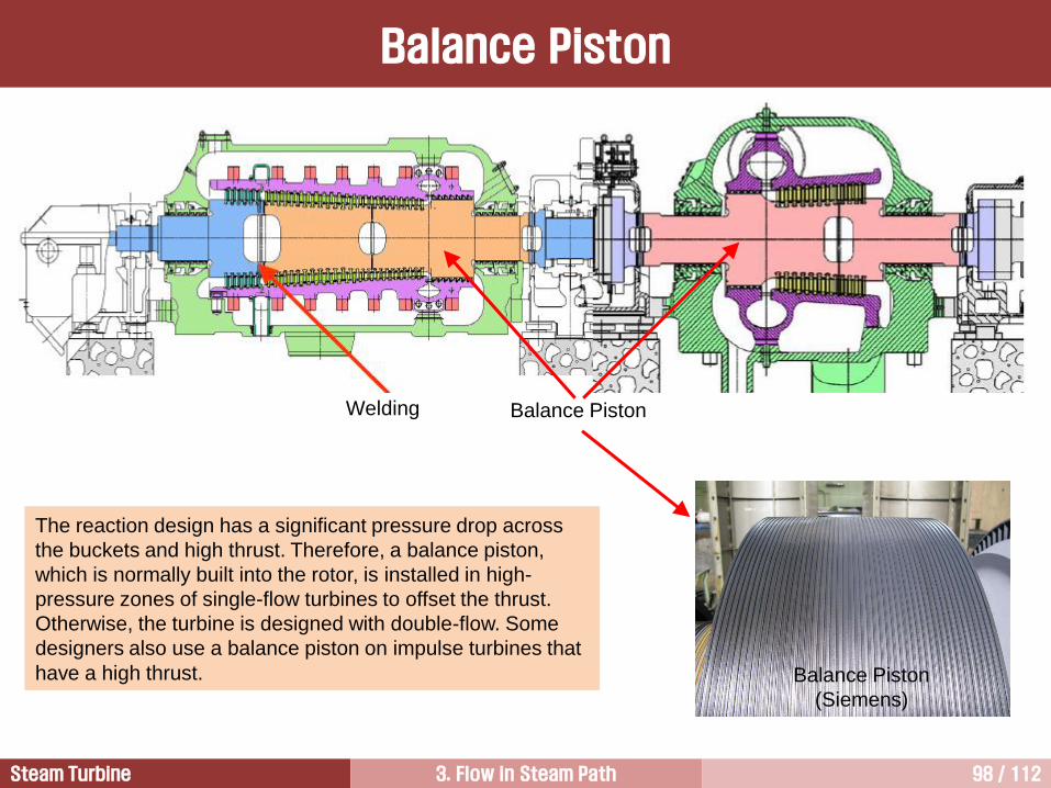
Welding Balance Piston
The reaction design has a significant pressure drop across
the buckets and high thrust. Therefore, a balance piston,
which is normally built into the rotor, is installed in high-
pressure zones of single-flow turbines to offset the thrust.
Otherwise, the turbine is designed with double-flow. Some
designers also use a balance piston on impulse turbines that
have a high thrust. Balance Piston
(Siemens)

Steam Turbine 3. Flow in Steam Path 99 / 112
What are the major advantages of double
flow structure?
1) Larger capacity
2) Smaller thrust force
3) Shorter LSB
Double Flow
Double flow can be employed to avoid a balance piston in reaction turbines which have a higher
thrust than impulse turbine
31 ppdlT
T = Thrust
d = mean diameter of blade row
l = active length of blade
p1 = pressure at the inlet of stage
p3 = pressure at the exit of stage
= degree of reaction at the mean dia.

Steam Turbine 3. Flow in Steam Path 100 / 112
Reaction Blades
Advantages Alstom
Higher aerodynamic efficiency
• Lower turning and accelerating flow in both nozzle and bucket allow design of higher efficient and tolerant
profiles
• Lower acceleration of the flow through the nozzle and bucket leads lower profile loss
Lower staging loading
Many stage can be designed with 50% reaction (all HP and IP stages, and front stages of LP turbine)
Symmetric velocity triangle (50% reaction stage)
• Use of same profile in the nozzle and bucket and it may contribute to cost down
• Near-zero interstage swirl
Because of the lower pressure drop, there is no need for costly diaphragm construction
It leads larger number of stages because of lower stage loading (roughly twice that of impulse stages for 50%
reaction stages).
Increase of axial thrust which leads higher dummy balance piston, i.e. increased leakage loss.
Drum-type rotor is suitable for reaction turbine and it leads higher leakage area at the hub section.
Degree of reaction at the hub and tip section is higher compared with impulse stage. Higher hub reaction
leads lower leakage loss, however higher tip reaction gives higher leakage loss.
Disadvantages

Steam Turbine 3. Flow in Steam Path 101 / 112
Steam Turbine Flow Model 2
Dimensionless Numbers 4
Fluid Dynamics 1
Thermodynamics and Fluid Dynamics for Steam Turbines 3
Impulse Turbine and Reaction Turbine 5
Stage Efficiency 6
Blade Profile Enhancement 7

Steam Turbine 3. Flow in Steam Path 102 / 112
Stage Efficiency
2, sin4ist
2
2
max,, sin ist
2c
u
ideal
actualst
p
p
버켓에서 생산하는 실제 동력
버켓에서 생산할 수 있는 이상 동력
=
( = velocity ratio)
(from ) 0,
d
ist
2
2
2,
sin21
sin22
rst
2
2
2
2
max,,sin1
sin2
rst
2c
u
Impulse Turbine Reaction Turbine
w3
w2
c2
u
c3
(b) = sin2
c2 w3
u
w2 c3
(c) > sin2
w2
c2
u
w3 c3
2
2
3
2
2
u
c2 w3
w2
3
c3
3
(a) < sin2

Steam Turbine 3. Flow in Steam Path 103 / 112
0.25 0.50 0.75 1.00 1.25 1.50
Velocity ratio ( )
0.0
0.1
0.2
0.3
0.4
0.5
0.6
0.7
0.8
0.9
1.0
1.1
Sta
ge
eff
icie
ncy
Impulse Reaction
2
2
2,
sin21
sin22
rst
2, sin4ist
2c
u
Stage Efficiency

Steam Turbine 3. Flow in Steam Path 104 / 112
Wake and Core Flow
Reaction stage has better adaptability for
core flow of nozzle and higher stage
efficiency
The wake is a velocity defect generated by the
boundary layers of the blade surfaces. If it is
undisturbed by other blades it would move
downstream along the direction of outlet-flow angle
while decaying slowly over three or four chord
lengths.
Velo
city
Number of revolution
1 2
Impulse
Bucket Reaction
Bucket

Steam Turbine 3. Flow in Steam Path 105 / 112
[연습문제 3.2]
증기터빈에 유입되는 주증기 조건(main steam conditions)이 30 MPa, 650C 이다. 이 증기는 1단 충동터빈(one-stage impulse turbine)을 등엔트로피 팽창(isentropic expansion)되어 350C로 빠져나간다. 이때 엔탈피 강하(isentropic enthalpy drop)가 540 kJ/kg 이다. 이 터빈을 single stage로 설계하는 데 따른 문제점을 검토하시오. 단, c2와 u가 이루는 각도는 13, 유량계수(flow coefficient)는 0.5, 노즐입구에서의 속도 c1은 매우 작다고 가정한다.
w2
c2
u
w3
u c3
Direction
of Rotation
c1
Number of Stages

Steam Turbine 3. Flow in Steam Path 106 / 112
[검토 결과]
노즐에서 발생하는 일은 없다. 아울러 노즐통로유동은 단열과정이기 때문에 노즐출구에서의 증기속도는 열역학 제1법칙을 이용하여 구할 수 있다.
편의상 노즐 입구속도는 0이라 가정하면, 열역학 제1법칙으로부터 다음 결과를 얻는다.
kJ/kg
1039.23 m/s
한편, c2와 u가 이루는 각도가 13 이며, 유량계수(flow coefficient) 0.5를 이용하여 u를 계산하면,
= cx/u
u = 1039.23 sin13 /0.5 = 467.6 m/s
증기터빈의 회전속도가 3,600 rpm인 경우, 블레이드 피치직경은 다음 식으로 구한다.
d = 2.48 m
따라서, 블레이드 회전속도와 피치직경이 매우 크기 때문에 블레이드는 큰 응력을 받게 되며, 큰 속도로 인해서 손실이 증가하게 된다. 결론적으로 이 조건에서는 증기터빈을 다단(multiple stages)으로 구성하는 것이 유리하다.
1212
2
1
2
212122
1wzzgcchhq
54022 21
2
2 hhc
60
)2/(2 ndu
2c
Number of Stages

Steam Turbine 3. Flow in Steam Path 107 / 112
Steam Turbine Flow Model 2
Dimensionless Numbers 4
Fluid Dynamics 1
Thermodynamics and Fluid Dynamics for Steam Turbines 3
Impulse Turbine and Reaction Turbine 5
Stage Efficiency 6
Blade Profile Enhancement 7

Steam Turbine 3. Flow in Steam Path 108 / 112
Impulse Blade vs. Reaction Blade
Conventional
1940
Laminar
1950
SCHLICT
1965
Super
1980
T
1937
VN
1953
T2
1968
T4
1980
TX
1995
GE
Siemens
Bucket Shape

Steam Turbine 3. Flow in Steam Path 109 / 112
Bucket Profile Enhancement
Siemens

Steam Turbine 3. Flow in Steam Path 110 / 112
Alstom
Bucket Profile Enhancement

Steam Turbine 3. Flow in Steam Path 111 / 112
Shrouded Blade
[ Shrouded Blade ] [ Free Tip Blade ]
Shrouded blades have reduced leakage losses because they have seal system at the blade tip.
Shrouded blades have better vibration characteristics because they are often interlocked to provide
mechanical damping.
Shrouded blades give better efficiency because they have better aerodynamic characteristics at the blade tip.
The tip vortex formed from open tip blade produce a large disturbed flow when it combined with secondary
flow in the blade passage.
However, the shroud creates increased stress levels.
[ Tip Vortex ]

Steam Turbine 3. Flow in Steam Path 112 / 112
질의 및 응답
작성자: 이 병 은 작성일: 2016.6.21 (Ver.7) 연락처: [email protected] Mobile: 010-3122-2262 저서: 실무 발전설비 열역학 증기터빈 열유체기술 발전용 가스터빈