3-line decontamination shelter operators manual · preparing for decon operations 4 general...
TRANSCRIPT

3-Line Decontamination Shelter
Operators Manual

7100 Holladay Tyler Road, Glenn Dale, MD 20769 Phone: (301) 352‐8800 Toll Free: (800) 598‐9711 www.imresponse.com
• Patented external articulating frame with cor‐rosion resistant anodized aluminum. Design facilitates rapid deployment; shelter can op‐erate with 30% of frame missing or broken.
• UV stable, fire retardant and chemical resis‐tant fabric on interior. Provides durability; protects exterior frame from contaminants and expedites post –use clean up.
• Stores to 45” x 45” x 45”. Space efficient for facilities with limited space.
• Separates into 3 decon lines. Enables patient privacy for male and female patients; added lane for non‐ambulatory.
• Interior Basin. Contains waste water within wash/rinse area of shelter.
• On/Off capable shower nozzles on interior fabric saturate patients with 360° of spray. Maintains system integrity and maximizes decon capability; nozzles can easily turn on or off for user’s specific needs.
3‐LINE SHELTER SPECIFICATIONS
Part Number SD3‐UZA08‐GZ
Interior Fabric Yellow Exterior—White Int. w/Skylight
Exterior Fabric White Thermal Screen
Nominal Size 20’ L x 11’ W
Shelter Stored Cube 45” x45” x 45”
Shelter Weight 215 lbs
Shipping Weight 358 lbs
# of Water Booms 2
# of Body Sprays 20 Total 0.4 GPM Each
# of Quick Connects for Hand Wands
4
SHELTER INCLUDES
• (2) Active Curtains with integrated water booms and nozzles w/tie‐downs
• (2) Isolation Curtains • (1) Interior catch basin • (2) Zippered Clothing Ports per Side • (1) 6” Diameter Snorkeled Port per Side • (1) 14” Diameter Snorkeled Port per Side • (2) 5‐Paneled Zippered End Doors w/ Velcro Strips • (1) Ground Cloth • (1) Anchor Kit • (1) Repair Kit • (1) Hose Adaptor Kit • (1) Transport Bag
3‐Line Decontamination Shelter for effective decontamination of both ambulatory and non‐ambulatory casualties within the same compact footprint.
3‐LINE DECONTAMINATION SHELTER
PRODUCT OVERVIEW
FEATURES & BENEFITS
Immediate Response Technologies, Inc. continuous development may cause this information and specifications contained herein to change without notice. IRT reserves the right to change, modify or discontinue any product listed. Images may be slightly different than actual products.
3

Table of Contents Chapter / Section Page 1 OVERALL SYSTEM DESCRIPTION......................................................................... 7
2 SAFETY PRECAUTIONS............................................................................................. 8
3 GENERAL OPERATING INFORMATION............................................................. 10
3.1 Shelter and Shelter Accessories .............................................................................. 10 3.2 Water Heater with Integrated Solution Injector ...................................................... 10 3.3 Shower Assembly .................................................................................................... 10 3.4 Casualty Conveyor................................................................................................... 10 3.5 Waste Containment .................................................................................................. 10
4 GENERAL DEPLOYMENT PROCEDURES........................................................... 12
4.1 Introduction.............................................................................................................. 12 4.2 Selection of Site........................................................................................................ 12 4.3 Staging of Equipment............................................................................................... 12
5 SHELTER DEPLOYMENT PROCEDURES ........................................................... 13
5.1 Place the Ground Cloth ........................................................................................... 13 5.2 Place Shelter for Deployment .................................................................................. 13 5.3 Expand the Shelter ................................................................................................... 13 5.4 Inspect the Fabric for Snags .................................................................................... 13 5.5 Deploy and Align the Shelter ................................................................................... 14 5.6 Align and Attach the Ground Cloth ......................................................................... 14 5.7 Fasten Red Weather Lock Straps............................................................................. 15 5.8 Anchor the Shelter.................................................................................................... 15 5.9 Roll up End Wall...................................................................................................... 15
6 DECON SET UP ........................................................................................................... 13
6.1 Install Lights ............................................................................................................ 13 6.2 Install Floor Basin ................................................................................................... 13 6.3 Install the Floor Risers ............................................................................................. 14 6.4 Install Waste Pump .................................................................................................. 14 6.5 Install Decon Hoses ................................................................................................. 14 6.6 Install Curtains ........................................................................................................ 15 6.7 (Optional Equipment) Flash Water Heater Set-Up ................................................ 15 6.8 (Optional Equipment) Position the Bladder ............................................................ 15 6.8.1 Place the Bladder in Operation ............................................................................ 15 6.9 Install Litter Equipment .......................................................................................... 15
7 SHELTER STRIKE PROCEDURES......................................................................... 17
7.1 Preliminary Preparations ....................................................................................... 17 7.1.2 Prepare Shelter for Strike ..................................................................................... 17 7.1.3 Uninstall Windlines and Ground Stakes ............................................................... 17 7.1.4 Release the Shelter................................................................................................ 17 7.2 Drop the Shelter...................................................................................................... 17

7.3 Compact the Shelter................................................................................................. 17 7.4 Place Shelter in Bag................................................................................................. 18 7.5 Complete Bagging Shelter ....................................................................................... 19 7.6 Fold the Ground Cloth............................................................................................. 19 7.7 Stow Ground Cloth, Close Bag................................................................................ 19 7.8 Clean and Bag Accessories...................................................................................... 20
8 SHELTER MAINTENANCE AND REPAIR................................................................ 21
8.1 Inspection and Repair .............................................................................................. 21 8.2 Repair of Frame....................................................................................................... 21 8.3 Replacement of Scissor Section ............................................................................... 21 8.4 Replacement of a Node ............................................................................................ 22 8.5 Repair of Fabric...................................................................................................... 23 8.5.1 Repair of Canopy or Liner.................................................................................... 23 8.5.2 Repair of Groundcloth .......................................................................................... 24
CUSTOMER COMMENTS ................................................................................................ 25
© ii

General Information 1 Overall System Description This manual provides an overview and presents the basic methodology for placing the system in operation. The methodology presented should be considered as simply a reference point. Individual system configurations may vary, and response teams will adapt the methodology to suit their specific staffing, protocols, and missions. Each team should practice, modify, and implement the methodology that best optimizes their performance and best accomplishes their stated mission.
For technical support or comments regarding this document, please contact:
TVI Corporation.
7100 Holladay Tyler Road
Glenn Dale, MD 20769
1 (301) 352-8800
© 7

2 Safety Precautions A. Never climb on shelter.
B. Use the correct number of people for shelter carry, shelter deployment, and shelter
strike.
C. Immediately vacate shelter upon releasing locking straps prior to collapsing shelter.
D. Keep hands and fingers out of shelter frame during the collapsing of shelter.
E. Keep open flames away from shelter fabrics.
F. Properly ventilate shelter when using fuel burning devices such as heaters and cooking stoves.
G. Use the proper number of wind lines and stakes.
H. Use proper stakes for various soil types and soil conditions.
I. Avoid placing stakes and wind lines in front of doors, paths, and walkways.
J. Regularly inspect and adjust wind lines and ground stakes.
K. Prepare for expected harsh weather by adding ground stakes, wind lines, and sandbags.
L. Remove accumulated snow from the roof of the shelter.
M. Secure shelter during gusty wind by closing doors and window covers.
N. Change to correct stakes if soil conditions change such as after prolonged rain or thawing.
O. When carrying or deploying the shelter keep your back straight and lift with your legs and arms.
P. The system has been designed for rugged performance in rough field conditions.
However, the shelter can be damaged if handled improperly. The following precautions in handling and storage must be carefully observed:
a. Lift or push the shelters by grasping a node, loop, or lift strap only. b. Avoid lifting, pulling, or pushing the shelter with the fabric. c. Stack the stored shelter only in its upright position and not on its side. Beams
should be standing up, with nodes on the bottom and top. d. When off-loading or loading, do not let the shelter drop or fall from the transport
vehicle.
© 8

e. Do not over tighten the compression belt strap around the center of the shelter when compacting the shelter for re-packing in the transport bag. Compression belts at the top or bottom around the array of nodes may be pulled as tight as possible.
f. Do not place the shelter directly on the lift arms of a forklift; first place it on a
pallet.
Note that the TVI articulating frame consists of a one-piece expanding semi-dome structure.
It expands in all directions simultaneously. Thus, the shelter must be deployed all at once by lifting and pushing upward in the center of the
roof section.
Attempts to deploy only one side or one end of the shelter will cause damage to the frame.
© 9
3 General Operating Information The system consists of several items of equipment with a specific function. Collectively, all items work together to achieve the design goals of the system. Your configuration may or may not include all of the systems here described. The equipment items can be grouped into several functional categories or modules intended to perform a specific task or service. These functional groups are:
3.1 Shelter and Shelter Accessories
This component provides an exterior shelter to protect operations from the weather and to provide privacy of operations. It provides interior compartments to separate processing functions and provide privacy for individual casualties.
3.2 Water Heater with Integrated Solution Injector
This component provides tempered wash solution and rinse water for the decontamination of casualties.
3.3 Shower Assembly
This component provides booms, hoses, spray nozzles, and hand sprayers to deliver wash and rinse water to individuals in efficient spraying.
3.4 Litter Conveyor
This component provides a transport mechanism for supporting and moving non-ambulatory casualties through the decontamination process.
3.5 Waste Containment (Basin)
This component provides a catchment basin for waster water, pumping mechanism for removing the waste, and storage bladders for containing the waste.
© 10

Summary The system will typically be deployed with the response team to the scene of a disaster involving victims who have been contaminated with a HAZMAT or WMD agent. It is designed to be placed into operation within minutes to minimize the input of exposure to the agent. The system is man portable, and requires no power equipment or special tools for setup. It is self-contained, except for water and power, to operate continuously for one hour without replenishment. It can be deployed in any open and reasonably level area.
© 11

Preparing for Decon Operations 4 General Deployment Procedures
4.1 Introduction
This section will provide a basic methodology for complete deployment of the decon shelter. The steps and procedures will be presented sequentially, but many will be done in parallel. See follow-on chapters for detailed instructions. The Basic Methodology assumes a Setup Team of two persons. If there are more persons on the Response Team, more tasks can be shared. Other members will also begin the process of casualty triage and management, and complete preliminary preparations for the decontamination process.
4.2 Selection of Site
The decon shelter can be set up almost any open and level place - parking lot, lawn, or inside. The most urgent requirement will be water, and the site should be as close as possible to a Fire Hydrant or Hose Bibb. Remember that water pressure will drop as distance increases. Thought should be given to the requirement for anchoring the shelter, particular if winds are present or likely. One side of the shelter should be placed directly toward or into the prevailing wind.
4.3 Staging of Equipment
Upon arrival at the scene and selection of the setup area, the response vehicle should be parked as close as possible to the area to minimize movement of decon shelter components. The equipment should initially be staged, using as many members of the Team as necessary. The components are likely to become packed tightly together, and may take some effort to unload. They should be placed convenient to the setup site, but not so close that they get in the way.
© 12

5 SHELTER DEPLOYMENT PROCEDURES
This section presents instructions for the deployment of the decontamination shelter. The shelter will be very easily erected if these instructions are followed. Note that TVI shelters do not function the same way as old-fashioned tents, but are state-of-the art articulating frames.
Please read Safety Precautions at the beginning of this document before attempting to erect or deploy the shelter.
The shelter requires a crew of three people to erect the shelter. These instructions are based upon the use of a three-person crew. This set-up team will be referred to as the “crew” and each individual will be referred to as a “person”.
5.1 Place the Ground Cloth
The bagged shelter should be carried and placed near the site it is to be erected.
of ag.
ter
nds of the
ps, one in
e
u loth
uch as possible.
that end of the cloth.
ake.
nt
1. Release the two outer retainer straps the b
2. Open the two outer flap covers of the bag.
3. Remove the ground cloth, and place it in the cenof the deployment site. The colored straps should be toward the eshelter. 4. Each person graspsa set of straeach hand. 5. Each person steps backward, pulling thground cloth open. Spread your arms apart as wide as yocan to spread the cas m 6. Persons A and B
each grasp a corner strap, step backward, and completely spread
8. If wind is moving the ground cloth, place a weight on the corners such as a rock or st
5.2 Place Shelter for Deployme
© 13
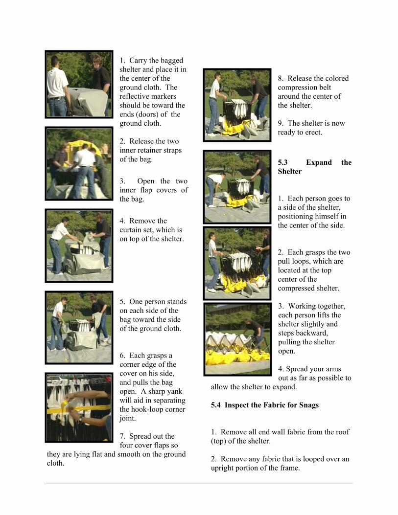
1. Carry the bagged shelter and place it in the center of the ground cloth. The reflective markers should be toward the ends (doors) of the ground cloth.
h.
g rner
joint.
smooth on the ground loth.
around the center of
9. The shelter is now ready to erect.
5.3 Expand the Shelter
o
positioning himself in the center of the side.
re at the top
center of the
steps backward,
d your arms out as far as possible to
.4 Inspect the Fabric for Snags
. Remove all end wall fabric from the roof
. Remove any fabric that is looped over an upright portion of the frame.
2. Release the two inner retainer straps of the bag.
3. Open the two inner flap covers of the bag.
4. Remove the curtain set, which is on top of the shelter. 5. One person stands on each side of the bag toward the side of the ground clot 6. Each grasps a corner edge of the cover on his side, and pulls the bag open. A sharp yank will aid in separatinthe hook-loop co
7. Spread out the four cover flaps so
they are lying flat andc
8. Release the colored compression belt
the shelter.
1. Each person goes ta side of the shelter,
2. Each grasps the two pull loops, which alocated
compressed shelter. 3. Working together, each person lifts the shelter slightly and
pulling the shelter open. 4. Sprea
allow the shelter to expand.
5
1(top) of the shelter. 2

3. Check the corners and ensure that no fabric is looped under the lower corner Node.
5.5 Deploy and Align the Shelter
son
shelter.
and side wall is vertical.
ide wall is
ch the shelter to the ground loth.
d
1. Persons A and B goes to the center of one end of the shelter. 2. Each grasps the lower center node. 3. Simultaneously, each lifts the end of the shelter up. 4. Lift up in one continuous motion, stepping inside andunder the roof, andpushing it up overyour head as far asthe arms will reach.
5. Persons A and Bhold fast, holding the shelter above
their heads. PerC enters the
6. With persons Aand B holding fast,person C pushes upon the roof with one hand while lifting slightly and
pulling in with the loop with the other hso that the
Note: The wall of the shelter should be aligned as much as possible with the edge of the groundcloth. 7. With persons A and B still holding fast, person C now goes to the other end of the shelter, and pushes up on the roof with one hand while lifting slightly and pulling in
with the loop with the other hand sothat the svertical.
8. The shelter is now standing erect. Persons A, B continue to hold the
shelter by the lift loops, while person C now moves to attac
The shelter is now completely deployed, anone person is holding the lift loop on each side.
5.6 Align and Attach the Ground Cloth
n
ches the
groundcloth.
elter as person C directs to align the shelter with the groundcloth.
1. Persons A and B continue holding oto the frame, while person C attathe shelter to
2. Persons A and B may move the
sh

5.7 Fasten Red Weather Lock Straps
(Located on outside of Shelter)
make it
operational
IT IS CRITICAL
Note: The lock straps are designed for use in windy weather and long term operations, and is not necessarily required for shelter operations, though your organization may elect toa standard
procedure.
THAT ALL THESE STRAPS BE
UNBUCKLED PRIOR TO COLLAPSING THE SHELTER.
AILURE TO DO SO WILL RESULT IN AMAGE TO THE FRAME.
. Attach buckle.
. Tighten straps.
.8 Anchor the Shelter
. Obtain the mallet and four stakes from e anchor kit.
take e
und
nodes.
ur
take in
feet nd
ace the loop at the end of the
line slip up the indline until it is taut.
8. Install windlines along the sides of the
oll up End
of the fabric that is the end wall.
FD
1
2
5
1th
2. Drive a sthrough the wirfootstop loop on thefour outside grolevel corner 3. Obtain four windlines and fostakes from the anchor kit. 4. Starting at a corner, attach a windline to the wire windline loop. 5. Place a sline with the loop and about fourfrom the shelter, adrive it into the ground. 6. Pl
windline over the stake, and slide the
w 7. Repeat the process for the other three corners.
shelter for each wire windline loop.
5.9 RWall
1. Grasp the bottom

.
. Roll up from the bottom
i
2 3. Use the Velcro strips to secure the rolled up fabric. 4. Repeat on other side f desired.
6 DECON SET UP
6.1 Install Lights
light
r
ne ach
xtension cord to end of light cord.
the extension cord out of one of the orts.
6.2 Install Floor Basin
partment.
1. Attach the fixture to the suspension loops inthe shelter ceiling. 2. If installing multiple lights, attach them togetheusing the male and
female connections to establish a single liof lights, with one power source. Atte 3. Pushp
1. Remove the basin from its bag and place it in the center of the shower com
ands at the top of one side of the basin.
together, t slightly and step
4. Open the basin as close to the side walls as possible.
is
i
the basin. 7. Both persons go to the other end of the basin.
2. Each person grasps a node in both h
3. Workinglifbackward, pulling the basin open.
5. Both persons go to one end of the basin, and push it against the side as close as possible. Make sure the endcentered between theshower isolation curtains.
6. Place the wall div der curtains and isolation curtains inside

8. Align the basin against the wall, and place the divider (curtains
sidewalls) and
inside the basin.
6.3 Install the
t
etw
u
e pump
.
. Place the pump in the lowest portion of the basin. (Ideally, the shelter will be
placed on a slight
the
outside through the n
the side walls.
4. Push the waste pump’s extension cord utside through the drain port.
i
that is designated as the
our
e nection on water heater.
2. Connect the red rinse hose to the fabric hose that is
ing
hoses to connect). ). Connect other end to the red connection on
e number of booms in the elter, the use of Y connector hoses or
ed to reduce the
along the
isolation curtains
Floor Risers
1. Place floor risers in the basin, starting
he center.
2. Place floor risers a solid floor is formed,
een the riser and
in
close together so that leaving a small gap bsidewall.
6.4 Install Waste P mp
1. Place thinside the basin in the gap at the edge
2
slope). 3. Connect the discharge hose to top of the discharge pump and push it
drain port, located oeither of
o
6.5 In
Note: follow
stall Decon Hoses
This operation should be done ng purging of the water heater.
1. Connect the blue rinse hose to the fabric hose
rinse line (depending on yconfiguration, you may have several
hoses to connect). Connect other end to thblue con
designated as the rinse line (dependon your configuration, youmay have several
water heater.
3. Depending on thshother apparatus may be requirthe number of hoses extending from

shelter to the water heater or other water source.
6.6 Install Curtains
1. Hang the Pre-Plumbed Shower Curtains
quick-connect hoses to establish curtains.
e shelter, putting the curtain bottoms inside the floor basin. Note that the curtains
ment flaps inside the shelter.
Position the ladder
the bladder at the side of the decon elter in the desired location.
ion: The bladder should be placed in a flat area
basin to facilitate drainage. It should be rviced from the Hot Zone.
ocation, which aves room for deployment of second
the bladder ith the connections on
.8.1 Place the
2. Connect the drain hose (extends from the helter) to the fill valve in the corner of the
bladder.
3. Connect the waste pump extension cord
arning! The waste pump should be
turned on only after thes.
e “dry”
m
lightly at each end
. If more than one conveyor is used, onnect them together, using the Hook and atch attachments found at the ends of each ection of conveyor.
down the length of the shelter to create 3 corridors. Attach
2. Hang the shower isolation curtains across th
are marked to correspond to the markings on the attach
6.7 (Optional Equipment) Flash WaterHeater Set-Up
Refer to Water Heater Operations Manual.
6.8 (Optional Equipment)B
1. Place sh Suggest
at the lowest point relative to the floor
se 2. Place the bladder in a llebladder. 3. Unfoldwtop.
6Bladder in Operation
1. Insert the vent valve in vent opening in the center of the bladder.
S
to a power source.
W showers are in r several minuteOperating thpump in a
continuous operation fo
condition will cause damage andfailure.
6.9 Install LitterEquipment
pouches. 2. Place and align the conveyors in the shelter. 3. Expand and
1. Remove the conveyors frotheir storage
position the conveyors by lifting sand stretching open as far as possible. 4cLs

6. Connect the hand sprayers to the overhead wash and rinse booms.
Note: Use caution in expanding and placing the Conveyor inside the Floor basin.
nsfer board on the
5. Place the conveyor traconveyor.

This section presents procedures for striking and packing the shelter system, its components, and any accessories.
PROCEDURES
. Remove all equipment from the shelter.
n set.
n wall or eiling are removed.
y HVAC ducts.
nes pulled to the shelter.
the door tieback lines.
3. Zip up the access ports and place them in
.1.3 Uninstall Windlines and Ground
. Disconnect and bundle all windlines.
2. Pull up all ground stakes.
straps.
IS CRITICAL THAT ALL STRAPS BE O DR
ng:
7 SHELTER STRIKE
7.1 Preliminary Preparations
1 2. Remove the curtai 3. Make sure that items hanging oc 4. Disconnect an 5. Remove any cable or wiring liin
6. Locate and lay out all bags.
7.1.2 Prepare Shelter for Strike
1. Release 2. Fully disconnect or open all door closures.
the Closed position.
7Stakes
1
7.1.4 Release the Shelter
1. Remove the footstop stakes. 2. Release the ground cloth hooks.
3. Unsnap the red fabric weather
IT DISCONNECTED PRIOR TOPPING THE SHELTER.
WarniAll personnel must exit the shelter.
It is now unsafe to occupy the shelter.
7.2 Drop the Shelter
1. Both persons go to one side of the shelter, one at each corner. 2. Grasp the ground level pull strap, lift
3. Continue to move ba
ntil the
the
rsons remain in position
pull strap.
up slightly, and pull the bottom of the
shelter outward.
ckward, holding the shelter side slightly off the ground, uroof section falls down and inward.
7.3 Compact Shelter
1. Both pe
at shelter corners holding on to the
17
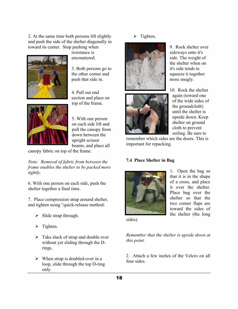
2. At the same time both persons lift slightly and push the side of the shelter diagonally in
4. Pull out end
pull the canopy from down between the
abric on top of the frame.
e packed more ghtly.
elter together a final time.
. Place compression strap around shelter, and tighten using “quick-release method:
.
er
p is doubled-over in a
loop, slide through the top D-ring
9. Rock shelter over
on
e shelter again (toward one of the wide sides of
l the shelter is upside down. Keep
sn
B
1. Open the bag so that it is in the shape of a cross, and place
Place bag over the shelter so that the two corner flaps are
the shelter (the long sides).
Remember that the shelter is upside down at this point.
2. Attach a few inches of the Velcro on all four sides.
only.
18
toward its center. Stop pushing when resistance is encountered. 3. Both persons go to the other corner and push that side in.
section and place on top of the frame.
5. With one personon each side lift and
upright scissor beams, and place all
canopy f Note: Removal of fabric from between the frame enables the shelter to bti 6. With one person on each side, push the sh
7
Slide strap through.
Tighten
Take slack of strap and double ovwithout yet sliding through the D-rings.
When stra
Tighten.
sideways onto it's side. The weight of the shelter when it's side tends to squeeze it togethermore snugly. 10. Rock th
remember which sideimportant for repacki
7.4 Place Shelter in
the groundcloth) unti
shelter on ground cloth to prevent soiling. Be sure to
are the doors. This is g.
ag
it over the shelter.
toward the sides of

3. Roll shelter back ,
d position.
ta plate).
ovided) fairly taut
to compress the shelter.
At this stage, only two flaps remain.
e “Data Plate” on it. That
flap is the LAST flap to be placed.
. Attach any remaining portions of the
.5 Complete Bagging Shelter
1. Place curtain set on top (Doing this rotects the curtains).
ly bagged shelter off of the ground cloth.
2. Carefully fold the
3. Fold first lengthwise and then
about three feet
e label is on top and the red and black
are visible at each end.
round Cloth, Close Bag
re the label is on top. Lift e two exterior flap covers over the top of
. Pull taut and straight. Make sure that the
ed cube more
4. Pull the closure flaps as straight and as taut as possible.
to upright positionbeing careful to maintain the bag in its correctly centere
4. Pull up on flaps all around to settle
5. Lay over flap that ched to Velcro on
shelter in the bag.
ide (this will be the set of flaps that does not have the da
attaother s
6. Attach the two interior straps (ifpr
One has th
7Velcro.
7
p 2. Lift and remove the partial
7.6 Fold the Ground Cloth
1. Brush and shake the ground cloth to remove dirt and other debris.
ground cloth, using the “accordion” or “parachute fold”.
end-to-end, and make a finished fold
square.
4. Make sure th
pair of pull straps
7.7 Stow G
1. Place the ground cloth on top of the shelter. Make suththe shelter. 2label is visible.
3. Attach the two exterior straps. Crossingthem will make the finishcompact.
19
5. Re-align and attach the VELCRO as necessary to ensure complete closure. 6. Align and tighten each strap as much as possible to compact the shelter.
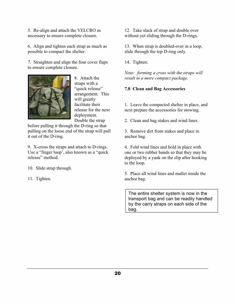
8. Attach the straps with a “quick release” arrangement. This will greatly
ext deployment.
so that pulling on the loose end of the strap will pull
-ring.
9. X-cross the straps and attach to D-rings. Use a “finger loop’, also known as a “quick release” method.
10. Slide strap through. 11. Tighten.
ngs.
a loop, slide through the top D-ring only.
ote: forming a cross with the straps will
d
bag stakes and wind lines.
4odto 5. Place all wind lines and mallet inside the anchor bag.
7. Straighten and align the four cover flaps to ensure complete closure.
facilitate their release for the n
Double the strap before pulling it through the D-ring
it out of the D
12. Take slack of strap and double over without yet sliding through the D-ri
13. When strap is doubled-over in
14. Tighten. Nresult in a more compact package.
7.8 Clean and Bag Accessories
1. Leave the compacted shelter in place, annext prepare the accessories for stowing. 2. Clean and 3. Remove dirt from stakes and place in anchor bag.
. Fold wind lines and hold in place with ne or two rubber bands so that they may be eployed by a yank on the slip after hooking the loop.
20
The entire shelter system is now in the transport bag and can be readily handled by the carry straps on each side of the bag.

8 Shelter Maintenance And Repair
8.1 Inspection and Repair
The shelter frame and fabric are very durable and not easily damaged. Strength of the frame is sufficient to allow operation with a significant portion of the frame removed which provides the option of delaying repairs until the mission is completed. In the event of damage, scissor sections may be simply removed and repaired after the mission. However, most repairs may be made easily while the shelter is in service without compromising the mission.
A repair kit is provided which includes all necessary items for field repairs. The types of damage, which may occur, include bent or broken struts, broken nodes, or ripped fabric on either canopy, liner, or floor fabric. Inspection for damaged scissors may be made from several locations. The entire frame may be inspected from either end of the deployed unit by pulling door panels to the outside and viewing between the liner and canopy. Inspection may be possible at and around windows or ports by viewing between canopy and liner through any openings. Severe damage such as broken struts will be possible to locate by examining the canopy and liner surfaces for protrusions or punctures.
Struts or nodes must be exposed for repair. This is accomplished by partially detaching either the canopy or liner to gain access. All repairs can be accomplished from the exterior (frame) or interior (fabric). Repairs MUST be made while shelter is in the standing position.
8.2 Repair of Frame
The frame is comprised of strut pairs, which are pinned to allow articulation in a scissor-like fashion, thus the term “scissor section.” There are three different scissor sections, which are associated with specific locations in the shelter.
Each scissor section type is identified by a color-coded rivet pin washer. Washers are color coded for all TVI built shelters. Replacement scissor sections are supplied in the repair kit. Note: frame repairs are best made with the shelter deployed. The frame is not under tension, and replacement parts are easily inserted into position.
8.3 Replacement of Scissor Section
Damaged, bent, or broken scissor sections should be replaced with a spare from the repair kit.
21

Be sure to use a section with the same color pivot washer. Scissor sections are replaced as follows: 1. Starting from the end closest to the damaged scissor section, remove the liner (or canopy) by using the 7/16-inch socket and ratchet, and the 7/16-inch combination wrench to remove the liner/canopy retainer bolts. 2. Continue to remove the liner/canopy until the damaged scissor section is exposed.
3. Using the Allen key and ratchet, remove the socket head bolts from each end of the scissor section (4 places).
4. Note the position and rivet pin washer color of the scissor section being removed, and select a matching replacement scissor section from the repair kit. 5. Open the scissor section by reversing one of the tube struts. 6. Position the replacement scissor section near the intended installation location and rotate to the required angle to match mounting notches in nodes. Note: the proper fit has been achieved if all four ends of the scissor section easily fit into the node mounting notches. 7. Using the Allen key and ratchet, reinstall the socket head bolts on each end of the scissor section (4 places).
8. Reattach the liner or canopy, using the removed retainer bolts.
8.4 Replacement of a Node
Damaged or broken nodes should be replaced with a new one from the repair kit. Nodes are replaced as follows: 1. Starting from the end closest to the damaged node, remove the liner (or canopy) retainer bolts by using the 7/16-inch socket and ratchet; and the 7/16-inch combination wrench. 2. Continue to remove the liner/canopy retainer bolts until the fabric can be removed to permit access to the damaged node. 3. Using the Allen key and ratchet, remove the socket head bolts from the four corners of the node.
22

4. Install a new node in the reverse order of removal. 5. Reattach the liner or canopy, using the removed retainer bolts.
8.5 Repair of Fabric
The canopy, liner and ground/floor cloth fabrics are extremely tough materials. However, small rips and punctures occasionally occur. These may be repaired in the field using the special tape supplied in the repair kit.
8.5.1 Repair of Canopy or Liner
Repairs may be accomplished while the shelter is in either the deployed or collapsed position. In most cases, canopy and liner are easily repaired while the shelter is deployed. 1. Determine size of tear/puncture. 2. 4. Clean the immediate area with common rubbing alcohol. Allow to dry. 3. Place the damaged area of the cloth on a smooth flat surface. 4. Cut tape somewhat larger than the damaged area.
23

5. Apply pressure to repair area. 6. Allow to set (10-15 minutes). 7. Repair is complete.
8.5.2 Repair of Groundcloth
The ground or floor cloth can be repaired either while in use or with the shelter removed. To repair holes or tears in the ground-floor cloth, use steps shown for repair of fabric.
24

LIMITED WARRANTY FOR
IMMEDIATE RESPONSE TECHNOLOGIES, INC. PRODUCTS Immediate Response Technologies, Inc. warrants to the original buyer that for a period of twelve months from the date of purchase or date of delivery, whichever occurs last, this product conforms to stated original specifications and is free from defects in material and workmanship.
Immediate Response Technologies, Inc. further warrants that their product(s) are fabricated from industry standard or customer specified materials using best commercial manufacturing practices, and that there are no known human or environmental hazards inherent in the product.
This warranty does not apply to damage resulting from improper installation, abuse, misuse, lack of proper maintenance, unauthorized modification, negligence, accident, natural or personal disasters, or the use of improper parts or improper repair procedures.
For shelter products, specifically but not exhaustively, this warranty does not include damage resulting from improper anchoring of shelters or failure to release locking mechanism’s prior to striking the shelter.
Failure to obtain training or user instructions given or approved by Immediate Response Technologies, Inc., OEM’s or government may be grounds for excluding a given product from coverage by this warranty. Immediate Response Technologies, Inc. sole responsibility under this warranty is to repair or replace a defective item, at its option, with a product that meets the standards described herein. This warranty does not include costs for transportation of the item to be repaired, costs for removal or reinstallation by the customer, nor travel and related costs incurred by Immediate Response Technologies, Inc. to make repairs or replacements at the customer’s site.
Immediate Response Technologies, Inc. must be notified in writing of any claim under this limited warranty promptly upon customer’s discovery of any defect. Customer must cease utilization of the product immediately after discovery and until the claim is reviewed by Immediate Response Technologies, Inc. and any required repair or replacement has been completed.
IMMEDIATE RESPONSE TECHNOLOGIES, INC. LIABILITY AND OBLIGATION UNDER THIS WARRANTY IS LIMITED TO THE REPLACEMENT COST OF ANY PRODUCT THAT DOES NOT MEET THE STANDARDS DESCRIBED ABOVE DURING THE WARRANTY PERIOD AND DOES NOT UNDER ANY CIRCUMSTANCE COVER INDIRECT OR CONSEQUENTIAL DAMAGES. IMMEDIATE RESPONSE TECHNOLOGIES EXPRESSLY DISCLAIMS ANY WARRANTY OF MERCHANTABILITY OR OF SUITABILITY FOR A PARTICULAR PURPOSE.

Product Innovation and Leadership Since 1977
7100 Holladay Tyler Road ! Glenn Dale, Maryland 20769 ! Tel: 301- 352-8800 ! Fax: 301-352-8818
Website: www.imresponse.com
WARRANTY CLAIM FORM
END USER INFORMATION
Organization:
Date:
Address:
POC:
Address:
Tel:
Address:
Fax:
City:
St:
Zip:
Email:
CONTRACT INFORMATION
Reference Contract/P.O. No.: Product(s) Received: Date Received:
Date Accepted:
First Date of Service:
CLAIM INFORMATION
Failed or Defective Item: Part No.:
Date Received:
Serial No.:
Date Accepted:
First Date of Service:
Date of Failure or Defect:
Please describe failure or defect and circumstances leading to its discovery
Use reverse side of this form and/or additional sheets as necessary.
Please include any photos or drawings that help describe the failure or defect.