3 operating controls and instruments 3.1. … · pointer indicator of the engine crankshaft speed...
TRANSCRIPT
15
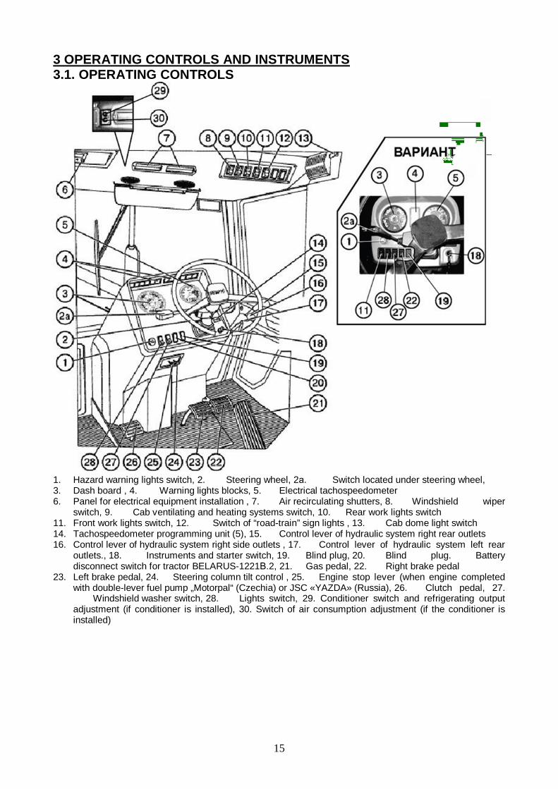
3 OPERATING CONTROLS AND INSTRUMENTS3.1. OPERATING CONTROLS
1. Hazard warning lights switch, 2. Steering wheel, 2 . Switch located under steering wheel,3. Dash board , 4. Warning lights blocks, 5. Electrical tachospeedometer6. Panel for electrical equipment installation , 7. Air recirculating shutters, 8. Windshield wiper
switch, 9. Cab ventilating and heating systems switch, 10. Rear work lights switch11. Front work lights switch, 12. Switch of “road-train” sign lights , 13. Cab dome light switch14. Tachospeedometer programming unit (5), 15. Control lever of hydraulic system right rear outlets16. Control lever of hydraulic system right side outlets , 17. Control lever of hydraulic system left rear
outlets., 18. Instruments and starter switch, 19. Blind plug, 20. Blind plug. Batterydisconnect switch for tractor BELARUS-1221 .2, 21. Gas pedal, 22. Right brake pedal
23. Left brake pedal, 24. Steering column tilt control , 25. Engine stop lever (when engine completedwith double-lever fuel pump „Motorpal“ (Czechia) or JSC «YAZDA» (Russia), 26. Clutch pedal, 27. Windshield washer switch, 28. Lights switch, 29. Conditioner switch and refrigerating outputadjustment (if conditioner is installed), 30. Switch of air consumption adjustment (if the conditioner isinstalled)

16
31. Range Shift Lever, 32. PTO control lever, 33. Fuel delivery control lever34. FDA and rear axle differential lock control unit, 35. Position control lever36. Draft control lever, 37. Stop of position control lever, 38. Battery disconnect switch39. PTO shift lever (independent - synchronous), 40. Ranges shift lever, 41. Parking brake lever
Starter and instruments switch (1)The switch (3) has 4 positions:• 0 — “Off”;• I — “Instruments, control lamps unit, radio
equipment power supply “On”• II — “Starter “On” (non-fixed position);• III — «Radio power supply when the engine is
stopped»
Important: Before operating tractor for the first time, study all of the controls andinstrument locations and their functions.

17
3.2.1 TACHOSPEEDOMETER 70.3813
. 1. Tachospeedometer ( 1):1. Engine crankshaft rotational speed scale, rpm.2. PTO II rotational speed scale –1000 rpm.3. PTO I rotational speed scale –540 rpm.4. PTO rotational speed display (LED).5. Engine running hours indication, h.6. Tractor speed indication, km/h.7. Display of engine running hours and tractor speed (LCD)8. Pointer indicator of the engine crankshaft speed
3.3. TACHOSPEEDOMETER CONTROL BOARDThe control board is installed in the instruments dashboard and serves for programmingthe tachospeedometer to the specific model of the Belarus tractor.
1. Button for setting the tachospeedometer to the programming mode and selecting theprogramming parameter on the tachospeedometer display2. Button for selecting the value of the coded parameter shown on the display.

18
3.4. COMBINED INDICATOR 8083
1 – Engine rotational speed indicator (pointer indicator).2 – PTO 1000 rotational speed scale (opposite to the respective value of the PTO
rotational speed).3 – PTO 540 rotational speed scale (opposite to the respective value of the PTO
rotational speed).4 – Five-digit indicator.5 – LED’s lighting up in the mode of programming the coefficients “K”, “R” and “Z”
(opposite to the respective LED).6 – LED’s lighting up in the mode of display of the motion speed “km/h” and total
engine running time “h” (opposite to the respective LED).7 – Alarm of the overvoltage in the tractor on-board power system (red) operates, if the
voltage exceeds 18.5 V.

19
3.5 INTEGRATED INDICATOR 80.3813 AND COMBINED INDICATING UNIT 8105(MOUNTED ON THE TRACTORS WITH THE INSTRUMENT DASHBOARD 826-3805010)The integrated indicator (hereinafter referred to as II) and the integrated indicatorprogramming console (hereinafter referred to as PC) show information about operatingparameters of tractor systems and assemblies and deliver to the operator data onmalfunctions or failures of a system. The ID includes indicators and pilot lights as shown inFigure below:
1 – speed indicator (pointer indicator);2 – engine speed indicator (pointer indicator);3 – PTO speed indicator (light indicator);3.1, 3.5 – PTO speed scale segments (yellow);3.2, 3.3, 3.4 – PTO speed scale segments (green);4.1, 4.2 – PTO speed scale range signaling devices (yellow);5 – headlight upper beam indicator pilot lamp (blue);6 – trailer turn indicator pilot lamp (green);7 – tractor turn indicator pilot lamp (green);8 — parking brake pilot lamp (red);9 – electric system high voltage pilot lamp (red);10 – low coolant level pilot lamp (yellow);11 – multifunctional indicator;
20
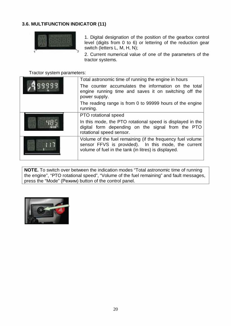
3.6. MULTIFUNCTION INDICATOR (11)
1. Digital designation of the position of the gearbox controllevel (digits from 0 to 6) or lettering of the reduction gearswitch (letters L, M, H, N);2. Current numerical value of one of the parameters of thetractor systems.
Tractor system parameters:Total astronomic time of running the engine in hoursThe counter accumulates the information on the totalengine running time and saves it on switching off thepower supply.The reading range is from 0 to 99999 hours of the enginerunning.PTO rotational speedIn this mode, the PTO rotational speed is displayed in thedigital form depending on the signal from the PTOrotational speed sensor.Volume of the fuel remaining (if the frequency fuel volumesensor FFVS is provided). In this mode, the currentvolume of fuel in the tank (in litres) is displayed.
NOTE. To switch over between the indication modes “Total astronomic time of runningthe engine”, “PTO rotational speed”, “Volume of the fuel remaining” and fault messages,press the “Mode” ( ) button of the control panel.

21
3.7 INSTRUMENT BOARD
The instrument board includes six gauges (11,12,13,14,15,16) with signal lamps (11a,12a, 13a, 14a, 15a, 16a).
The gauge of oil pressure in the transmission hydraulic system (11).The scale of oil pressure gauge has three zones:- working — from 800 to 1500 kPa (green color);- emergency (two) — from 0 to 800 kPa and from 1500 to 1800 kPa (red color).
ATTENTION! Working zone is scale section from 900 to 100kPa (9…10kgs/cm2). It isforbidden to operate the tractor when oil in transmission is under 900 kPa (9 kgs/cm2).
(11a) – signal lamp of emergency oil pressure in transmission hydraulic system – is notused.
Gauge to indicate air pressure in the pneumatic system (12).2The scale of the gauge has three zones:- working – from 500 to 800 kPa;- emergency (two) — from 0 to 500 kPa and from 800 to 1000 kPa (red color).A signal lamp (12a) (red color) is built in the gauge scale which lights up when thepressure in the pneumatic system drops below 500 kPa.
Voltage gauge – (13) The voltage gauge 5) indicates accumulator batteries voltage with the engine stoppedwhen the key of starter and instruments switch is set in position “I”. With the enginerunning the voltage gauge indicates voltage on generator terminals. A pilot lamp (13a) ofred color is built in the scale of voltage gauge. It is used only with 24V starting system. Itindicates the process of the additional battery charge with 24V it checks the workability ofthe voltage converter.
Gauge to indicate fuel volume in the tank with signal lamp of reserve fuel volume in thetank - (14a) The scale of the gauge has the divisions “0-1/4-1/2-3/4-1”. Do not let the tank becomeempty (the gauge pointer is in the zone of orange color)!
22
Gauge of engine coolant temperature (15) with emergency temperature lamp (15a) Readsdata from the engine control unit (ECU). The gauge scale has three zones:- working – from 70 to 100 ° (green color);- emergency (two)– from 70 to 100 ° and from 100 to 120 ° (red color);
An emergency temperature lamp (15a) operates in two modes:) lights up and operates in a flashing mode with coolant values from 109 ±0,5 up to and
including 112±0,5 ° .b) glows in a continuous mode with coolant temperature values from 113±0,5 ° andhigher.
Oil pressure gauge in the engine lubricating system (16) with build in signal lamp ofemergency oil pressure drop (16a) (red color). Reads data from the engine control unit(ECU). The gauge scale has three zones:- working – from 100 to 500 kPa (green color);
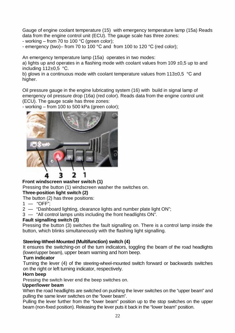
Front windscreen washer switch (1)Pressing the button (1) windscreen washer the switches on.Three-position light switch (2)The button (2) has three positions:1 — “OFF”;2 — “Dashboard lighting, clearance lights and number plate light ON”;3 — “All control lamps units including the front headlights ON”.Fault signalling switch (3)Pressing the button (3) switches the fault signalling on. There is a control lamp inside thebutton, which blinks simultaneously with the flashing light signalling.
Steering-Wheel-Mounted (Multifunction) switch (4)It ensures the switching-on of the turn indicators, toggling the beam of the road headlights(lower/upper beam), upper beam warning and horn beep.Turn indicatorTurning the lever (4) of the steering-wheel-mounted switch forward or backwards switcheson the right or left turning indicator, respectively.Horn beepPressing the switch lever end the beep switches on.Upper/lower beamWhen the road headlights are switched on pushing the lever switches on the “upper beam” andpulling the same lever switches on the “lower beam”.Pulling the lever further from the “lower beam” position up to the stop switches on the upperbeam (non-fixed position). Releasing the lever puts it back in the “lower beam” position.

23
Front windscreen wiper switch (1)Pressing the button (1) switches on front windscreen wiper.
Cab heater and fan switch (2)Pressing the button (2) switches on the cab air ventilation.The switch has 3 positions:1 — “OFF”(the upper part of the button is sunk to the maximum);2 — “Low air supply mode ON”;3 — “High air supply mode ON”.
Rear working lights switch (3)Pressing the button (3) switches the rear working lights and the roof backlight lamp.
Front working lights switch (4)Pressing the button (4) switches on the front working lights and the button backlight lamp.
“Road-train” sign lighting switch (5)On pressing the button (5), the three orange lights on the roof forepart are switched onand the button is backlit.
Conditioner(clima utit) control
On the conditioner control unit there are switches (1) (2).1 – Airflow adjustment switch;2 – Conditioner switch off and refrigerating capacity adjustment.

24
3.8. CHECK INDICATORS OF THE DASHBOARD (DASHBOARD 80-3805010- 1)
1 and 14 – Buttons for testing the serviceability of the control lamps unit. On pressing thebutton, all the lamps shall be lit.; 2 – Air filter blocking. The control lamp (orange) lights upwhen the maximum allowed level of filter blocking is exceeded and it needs cleaning; 3 –Reserved; 4 – Engine start lamp: This orange control lamp lights up on turning the starterswitch key to position II to indicate that the starting system functions properly. If the lampblinks at the frequency of 1.5 Hz, the gearbox control lever is not in neutral position or theengine starting locking switch circuit is out of order. If the lamp blinks at the frequency of3.0 Hz, there is a failure in the alternator phase winding circuit. Eliminate the fault andrestart.; 5 – Starting aid lamp (orange); 6 – HPS emergency oil pressure. The lamp (red)lights up when oil pressure in HPS feeding system is below the allowable level; 7 –Reserved; 8 – Upper beam indicator: Blue control lamp lights up when switching on theupper beam of the front headlights; 9 – Rear axle differential locking control lamp. Thelamp (green) is on when switching automatic differential locking (ADL); 10 – Reserved; 11 –Tractor turn indicator (green); 12 – Trailer turn indicator (green); 13 – Parking brakeindicator (red).
3.10 CONTROL LAMPS OF THE DASHBOARD (DASHBOARD 826-3805010)
1 – Reserved indicator (green); 2 – Reservedindicator (green); 3 – Reserved indicator (red); 4 –HPS emergency oil pressure. The lamp (red) lightsup when oil pressure in HPS feeding system isbelow the allowable level; 5 – Air filter blocking(orange). The control lamp lights up when themaximum allowed level of filter blocking isexceeded and it needs cleaning; 6 – Reservedindicator (blue); 7 – Rear axle differential lockingcontrol lamp (green). The lamp (green) is on whenswitching automatic differential locking; 8 –Starting aid lamp (orange); 9 – Reserved indicator(red); 10 – Reserved (red).

25
3.11 ELECTRIC EQUIPMENT CONNECTOR COMPONENTS
A combined multipin socket is designed for connecting the trailer electrical equipment orelectrical equipment of trailed agricultural implement and service lamp. It is installed on thecab’s rear support. A plug of the wire bundle of the hitched machines and a plug of servicelamp are connected to the socket.Socket connection terminal marking:– Turn indicator, left;– Horn;– “Ground”;– Turn indicator, right;– Right clearance light;– Stop light;– Left clearance light;– Service lamp connection.
3.12 GEARBOX CONTROL (16F+8R)
The gearbox is controlled by two levers: a lever of ranges shifting (1) and a lever of gearsshifting (2).Select the required ranges and gears in accordance with the shifting patterns I and II asshown on the figure below.
IMPORTANT! In order to shift the gear correctly smoothly, without jerks, move the gearshifting lever (2) in accordance with the pattern (see the figure above) and keep it presseduntil the gear is switched.
26
3.13 GEARBOX CONTROL (24F+12R) (IF INSTALLED)
Gears shifting lever (2)The shifting pattern is shown in the figure on the right(pattern I).“On” button (2 ) of gearbox reducer low gear (L).On” button (2 ) of gearbox reducer high gear (H).
Ranges shifting lever (1)The shifting pattern is shown in the figure on the right(pattern II).
– two low ranges of forward motion; – two high ranges of forward motion;
R – two ranges of reverse motion; –high pass of gearing;
L – low pass of gearing.
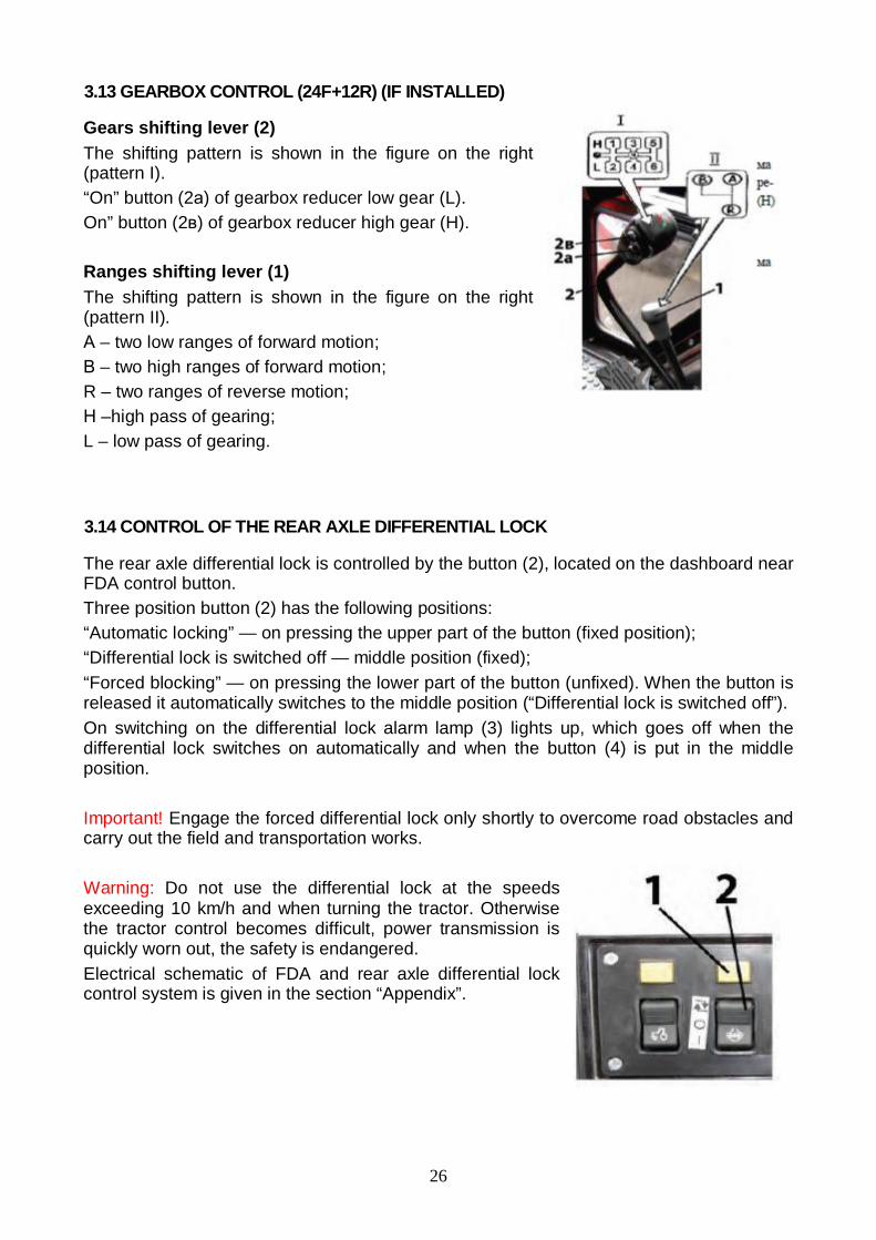
3.14 CONTROL OF THE REAR AXLE DIFFERENTIAL LOCK
The rear axle differential lock is controlled by the button (2), located on the dashboard nearFDA control button.Three position button (2) has the following positions:“Automatic locking” — on pressing the upper part of the button (fixed position);“Differential lock is switched off — middle position (fixed);“Forced blocking” — on pressing the lower part of the button (unfixed). When the button isreleased it automatically switches to the middle position (“Differential lock is switched off”).On switching on the differential lock alarm lamp (3) lights up, which goes off when thedifferential lock switches on automatically and when the button (4) is put in the middleposition.
Important! Engage the forced differential lock only shortly to overcome road obstacles andcarry out the field and transportation works.
Warning: Do not use the differential lock at the speedsexceeding 10 km/h and when turning the tractor. Otherwisethe tractor control becomes difficult, power transmission isquickly worn out, the safety is endangered.Electrical schematic of FDA and rear axle differential lockcontrol system is given in the section “Appendix”.

27
3.15 FDA DRIVE CONTROL
FDA drive is controlled by the button (2), located on the board above the right control unit.The button (2) has three fixed positions:“FDA is automatically “on” — on pressing the upper part of the button;“FDA is “off” — middle position of the button;“Forced FDA engagement” — on pressing the lower part of the button.
On engaging FDA drive the alarm lamp (1) lights up. The lamp goes out on putting thebutton (2) in the middle position and in the moment of switching off the drive in theautomatic mode.
Attention!1. Operating on the roads with hard surface switchoff the FDA (middle position of the button (2) inorder to prevent tyres and drive parts fromincreased wear.2. Use the forced FDA engaging mode shortly onlyto overcome obstacles and when operating onreverse,3. It is categorically forbidden to operate in themode of forced FDA engagement when the speed isover 15 km/h.4. It is categorically forbidden to use FDA in themode of automatic engagement by the reverse motion.
Electrical schematic of FDA and rear axle differential lock control system is given in thesection “Appendix”.
Note: A braking relay is installed in the electrical line of FDA drive control, it ensuresautomatic switching on of FDA when pressing synchronized pedals of tractor brakes.

28
3.16 SWITCHING ON REAR PTO SHAFT
The lever (1) has 2 positions: “PTO is engaged” — extreme upper position, “PTO is disengaged” — extreme lower position.
Independent and synchronous PTO drives
The lever (2) has three positions: “Independent drive is engaged” — extreme right
position; “Synchronous drive is engaged — extreme left position; “Disengaged” — middle position.
Engage the synchronous PTO drive only at low gears on minimum engine idle speeddoing the following: Start the engine and set the minimum idle speed; Press home the clutch pedal and engage I or II gear; Release the clutch pedal slowly and simultaneously turn the lever (2) in the extreme left
position.
Speed switch of independent PTO drive
Independent drive lever (1) has two positions:I — 540 rpm — extreme, contraclockwise;II — 1000 rpm — extreme clockwise.To set a required PTO speed release the bolt (2), turnthe lever (1) and tighten the bolt (2).
Important! Use the PTO synchronous drive only at low gears at tractor motion speednot higher than 8 km/h. Otherwise tractor power train may get seriously damaged.
29
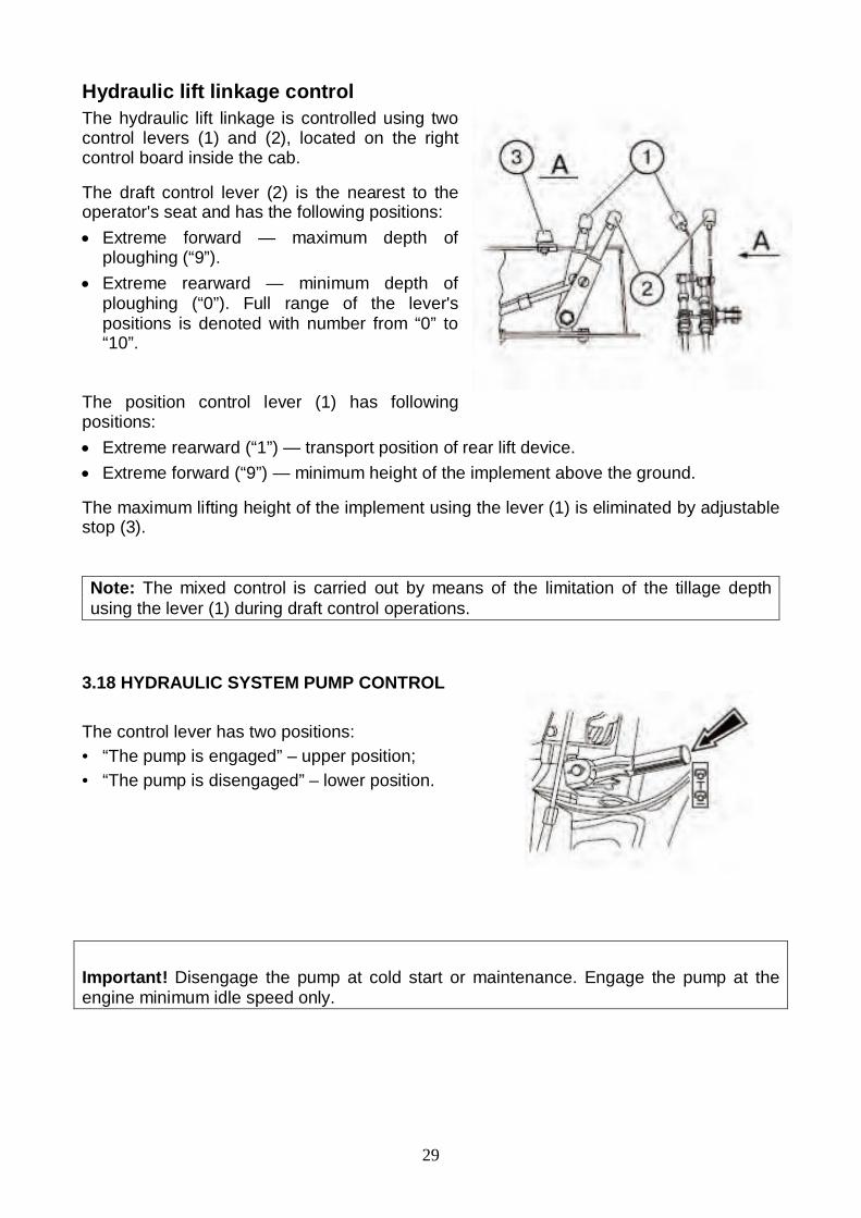
Hydraulic lift linkage controlThe hydraulic lift linkage is controlled using twocontrol levers (1) and (2), located on the rightcontrol board inside the cab.
The draft control lever (2) is the nearest to theoperator's seat and has the following positions: Extreme forward — maximum depth of
ploughing (“9”). Extreme rearward — minimum depth of
ploughing (“0”). Full range of the lever'spositions is denoted with number from “0” to“10”.
The position control lever (1) has followingpositions: Extreme rearward (“1”) — transport position of rear lift device. Extreme forward (“9”) — minimum height of the implement above the ground.
The maximum lifting height of the implement using the lever (1) is eliminated by adjustablestop (3).
Note: The mixed control is carried out by means of the limitation of the tillage depthusing the lever (1) during draft control operations.
3.18 HYDRAULIC SYSTEM PUMP CONTROL
The control lever has two positions:• “The pump is engaged” – upper position;• “The pump is disengaged” – lower position.
Important! Disengage the pump at cold start or maintenance. Engage the pump at theengine minimum idle speed only.

30
3.19 GEARBOX OIL PUMP CONTROLThe gearbox oil pump control lever (1) can have twofixed positions:I — “Pump drive from engine” (normal operating
position) — the lever (1) is turned counterclockwise(when looking at GB from the left tractor side)relative to the axis (3) until the lower edge of thelever slot stops and is fixed by the bolt.
II — non-working position.
Important! Set the lever (1) in the position II when there is a necessity to remove and tomount the assembled GB pump drive (4) and then fix the lever (1) in the position I again.
3.20 HYDRAULIC SYSTEM DISTRIBUTOR CONTROL
Each of the three remote levers (1, 2, 3), controls theremote cylinders and has four positions: “Neutral” — low middle (fixed); “Lift” — low (non-fixed); after releasing the lever
returns to “neutral"; “Positive lowering” — upper middle (non-fixed)
between the “float” and “neutral”. After releasing thelever returns to «Neutral";
“Float” — upper (fixed)

31
3.21 CHANGING OF STEERING WHEEL POSITION
To adjust the height of the steering wheel, proceed asfollows: Remove the cover (2); Unscrew the clamp (1) for 3…5 turns; Set the steering wheel in the required position; Tighten the clamp (1) manually and fix the cover (2)
back.
Note: Steering wheel height adjustment range is 100mm.
The steering column can tilt to four different positionsfrom 25° to 40° relative to horizontal line in increments of5°). In order to tilt the steering column, pull the handle (3)on.

32
3.22 “BELARUS” 80-6800010/80 -6800000 seat
The 80-6800010 seat is distinguished from the 80 -6800000 seat by the mounting seatand a possibility to complete the 80-6800010 seat with elbows and a safety belt.Important! Before operating the tractorAdjust the seat to the most comfortableposition. All adjustments should be madewhile sitting in the seat.The seat is considered correctly adjustedaccording to the weight if it moves on thehalf of its travel under the operator'sweight (suspension travel is 100mm).
Seat adjustments:According to the driver's weight from 50 till 120 kg.Seat adjustments are carried out by the lever (1). To adjust the seat to larger weightmove the lever pawl (1) to the position “A” and tight the springs using to-and-fro motion.To adjust the seat to the smaller weight move thelever pawl to the position “B” and release thesprings using to-and-fro motion.
Back inclination adjustment within the rangefrom 15 to 20 (for the seat 80-6800010).Carried out by the flywheel (2). To increase theangle of the back inclination turn the flywheelclockwise, to reduce it turn the flywheelcontraclockwise.
Back inclination adjustment within the rangefrom 5 to 25 (for the seat 80 -6800000)Carried out by the lever (2). Lift the lever upwardsto the stop, move the back and release the lever.The back will be fixed in the given position.Longitudinal seat adjustment within the rangeof 160 mm.Carried out by the lever (3). To move the seatforward/backward pull the lever upwards, movethe seat and release the lever. The seat isautomatically fixed in the necessary position.Height adjustment within the range of 60 mm.The seat has three height positions “lower”,“middle” and “upper”. To move the seat from the“lower” position to the “middle” one or from the“middle” position to the “upper” one smoothly liftthe seat upwards to the clickwork (the indicatorclick sounds). To move seat from the “upper”position to the “lower” one move the seat sharplyupwards to the stop and move down.
Note: It is not possible to move the seat from the“middle” position to the “lower” position.

33
3.23 “REVERSE POSITION” (FOR THETRACTOR WITH THE REVERSECONTROL PANEL “BELARUS-1221 .2”).To set the seat to the reverse position it isnecessary to turn the clamps “ ” off andmove them out of the panel bracketsedges “ ”, lift the lever “ ” and turn theseat half-way (180°). Sharply lift and pull itthe seat upwards. Set the screws “ ” intothe slots of the panel brackets “ ”, put thescrew « » on in the brackets to the stopand fasten the clamps “ ” with the turningtorque 44 … 56 Nm.
3.24 THE SEAT GRAMMER MSG85/721(IF INSTALLED)
Important! Prior to beginning theoperation of the tractor, adjust the seat tothe position being the most convenientfor you. Perform all the adjustmentswhile sitting on the seat.
Seat adjustments:According to the driver's weight within therange from 50 to 130 kg with the massindication every 10 kg. Carried out by thelever (1). To adjust the seat to the biggerweight turn the handle clockwise, to adjust theseat to the lower weight turn the handlecontraclockwise.Adjustment of back inclination from -10° 35°.Carried out by the lever (2). Lift the lever upwards to the stop, move the back and releasethe lever. The back is fixed in the necessary position.Longitudinal seat adjustment within the range of 150 mm.Carried out by the lever (3). To move the seat forward/backward pull the lever upwards,move the seat and release the lever. The seat is automatically fixed in the necessaryposition.Height adjustment within the range of 60 mm. The seat has three height positions“lower”, “middle” and “upper”. To move the seat from the “lower” position to the “middle”one or from the “middle” position to the “upper” one smoothly lift the seat upwards to theclickwork (the indicator click sounds). To move seat from the “upper” position to the “lower”one move the seat sharply upwards to the stop and move down.
Note: It is not possible to move the seat from the “middle” position to the “lower”position.

34
3.25 CAB HEATER CONTROLTo put the cab heater into operation,proceed as follows:1. Open the cock (1) from the left-hand sideof the engine over fine fuel filter. Turn thecock handle counterclockwise against thestop. Make sure the coolant circulates inheater system slightly turning off the drainplug (4) from the right-hand side of the cab.Tighten the drain plug.2. Turn on the heater fan using the switch(3), located on the upper panel of cab roof.3. By opening or closing recirculationshutters (2) you can control the amount offresh air coming into the cab from theoutside. Adjust the airflow direction throughcontrolled channels.
Note: If you want to warm-up air in the cabquickly, open the recirculation shutters fullyand switch the heater fan to high speedusing switch (3).
Drain plugs (4) from the left-hand side andfrom the right-hand side of the cab areprovided for system emptying filled withwater in the frost season. To avoid iceplugs, aerate the system with compressedair, but before it close water dump valvesfrom water radiator and engine cylinderblock and replace the radiator cap.
Note: For vent mode of the system in thewarm season the cock (1) has to be closed.
35
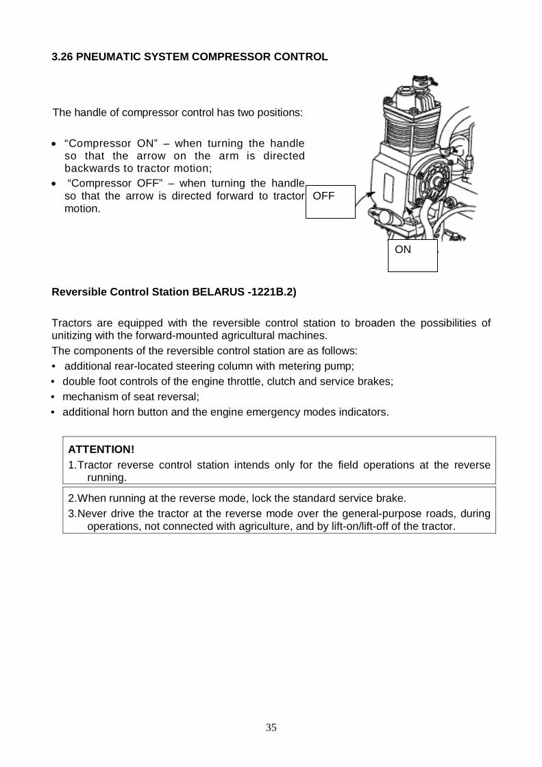
3.26 PNEUMATIC SYSTEM COMPRESSOR CONTROL
The handle of compressor control has two positions:
“Compressor ON” – when turning the handleso that the arrow on the arm is directedbackwards to tractor motion;
“Compressor OFF” – when turning the handleso that the arrow is directed forward to tractormotion.
Reversible Control Station BELARUS -1221 .2)
Tractors are equipped with the reversible control station to broaden the possibilities ofunitizing with the forward-mounted agricultural machines.The components of the reversible control station are as follows:• additional rear-located steering column with metering pump;• double foot controls of the engine throttle, clutch and service brakes;• mechanism of seat reversal;• additional horn button and the engine emergency modes indicators.
ATTENTION!1. Tractor reverse control station intends only for the field operations at the reverse
running.
2. When running at the reverse mode, lock the standard service brake.3. Never drive the tractor at the reverse mode over the general-purpose roads, during
operations, not connected with agriculture, and by lift-on/lift-off of the tractor.
OFF
ON

36
3.27 REVERSIBLE STATION CONTROLSThe additional reverse controls are located at the rear side of the cab as shown in thefigure below:1 - the clutch is disengaged when pressing the pedal. Clutch engagement takes place
by pedal release.2 –steering wheel of tractor turning (it is taken from the steering column of forward
motion (9)).3 –brakes pedal. Both tractor brakes and pneumatic drive of trailer brakes are engaged
by depressing the pedal.4 –foot throttle. Fuel feeding is increased by pressing the foot throttle.5 – horn button.6 –fuel delivery control lever. Extreme rearward position (on reverse) corresponds to
full fuel delivery, extreme forward position corresponds to engine stopping.7 –gearbox ranges selecting lever (see pattern I).8 –transmission speed control lever (see pattern II).9 –steering column of forward motion.
To adjust the tractor for reverse operation, proceed as follows:• lock the standard brake pedals;• transfer the steering wheel to the additional steering column. For that purpose turn offthe handwheel of the steering wheel fixation, transfer the steering wheel and fix it at therequired height;• turn the revolving seat for reverse operations;• set the HPS switch cock to the “reverse” position.