3 prismaflex basic setup operation
TRANSCRIPT
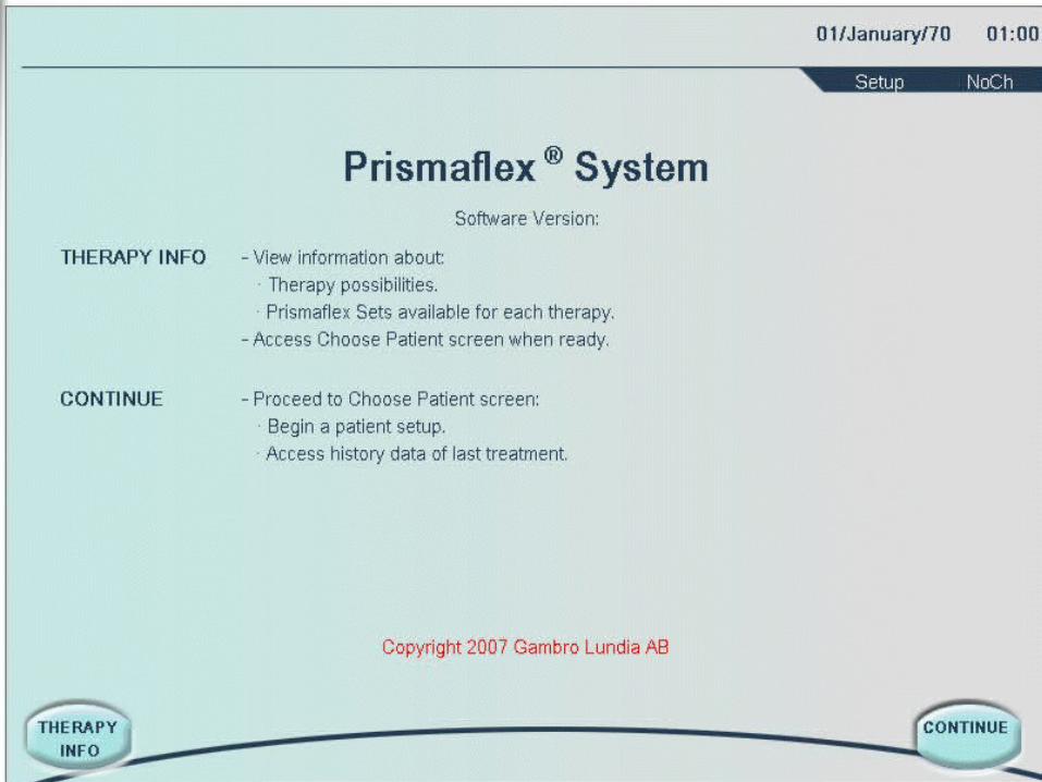
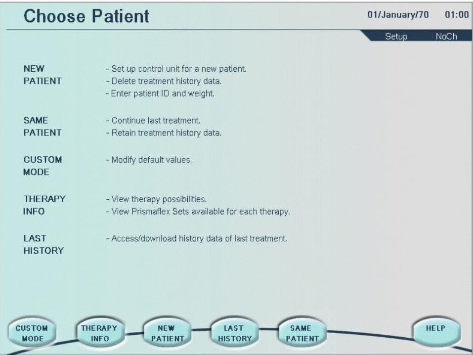
Prismaflex SystemBasic Set-up
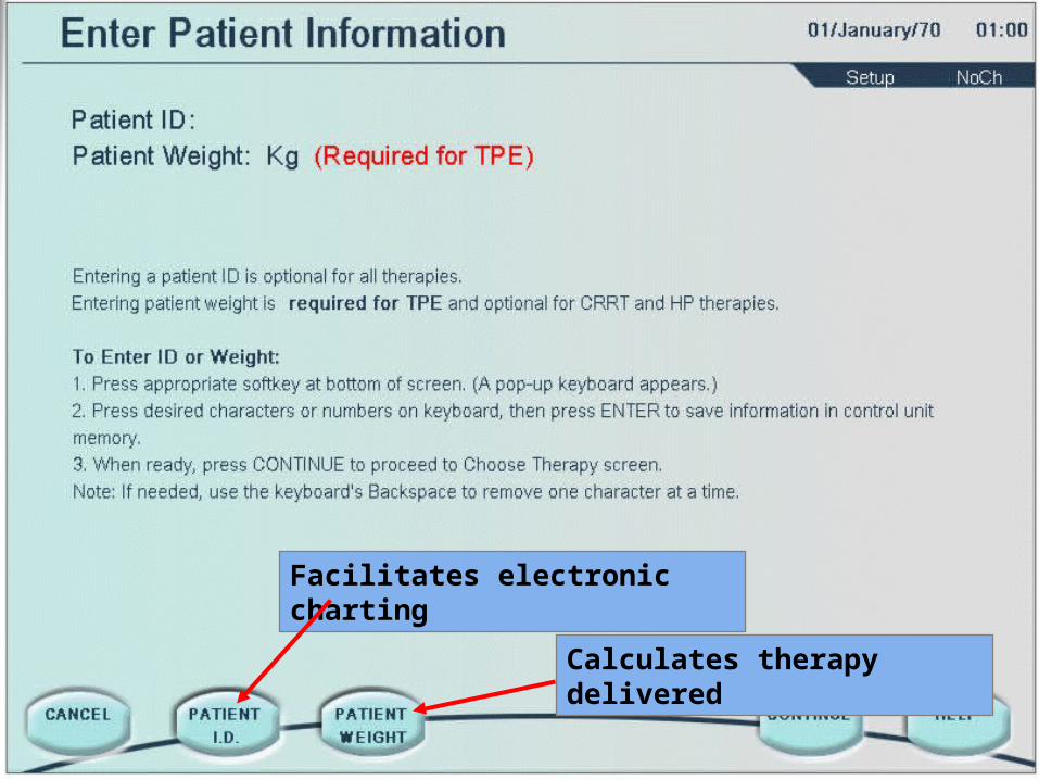
Facilitates electronic charting
Calculates therapy delivered
®
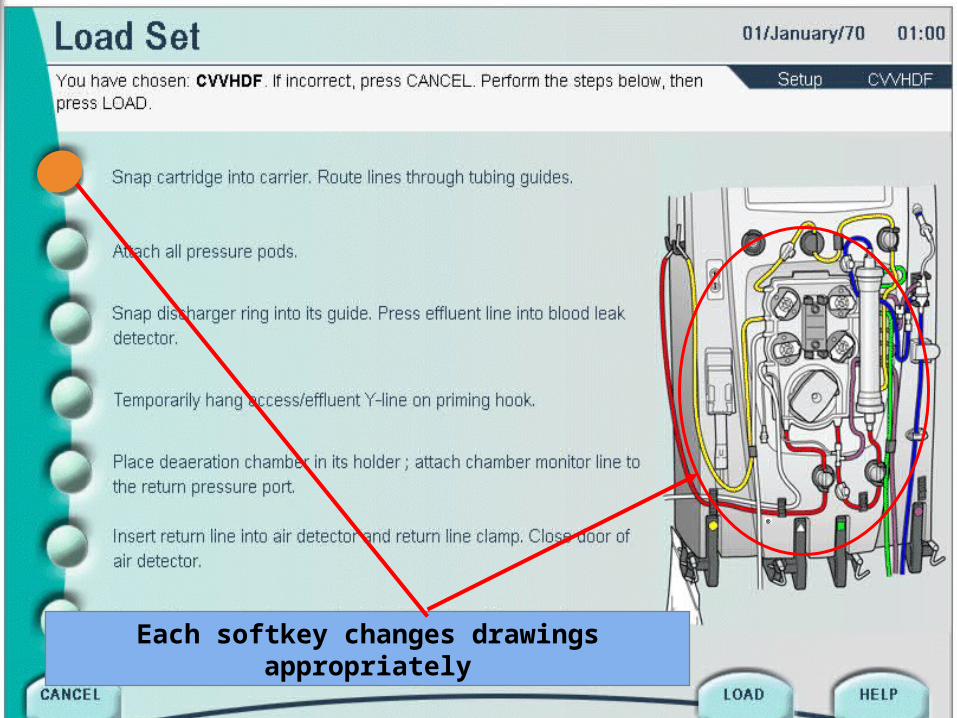
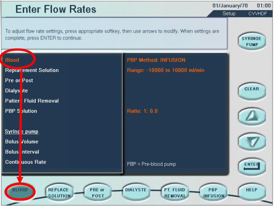
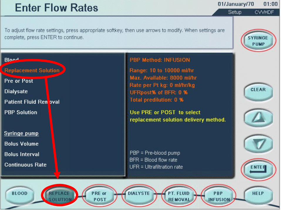
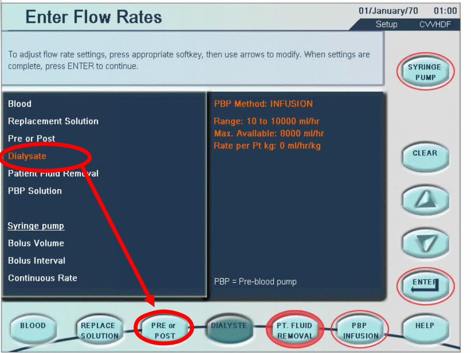
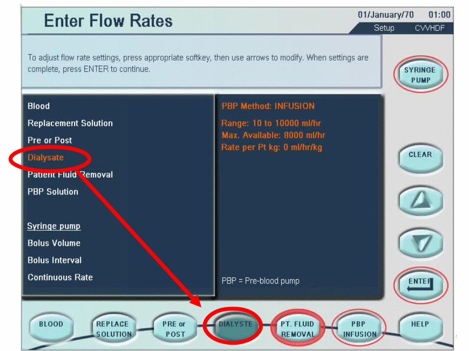
Each softkey changes drawings appropriately
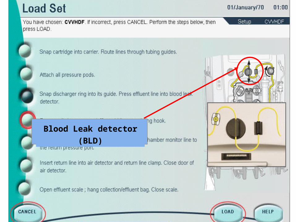
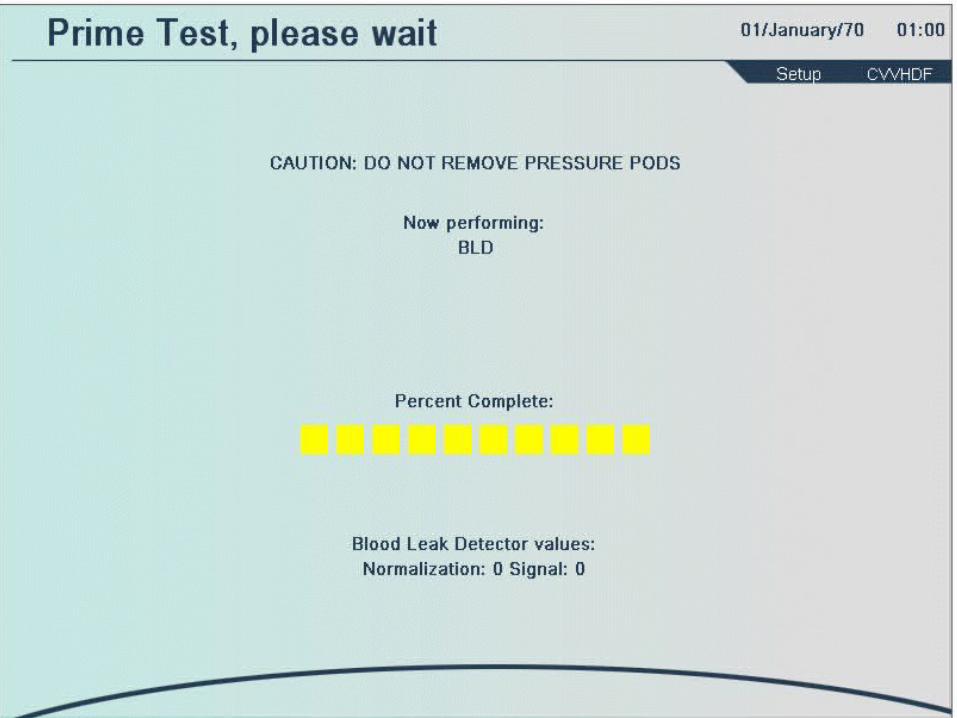
Blood Leak detector
(BLD)
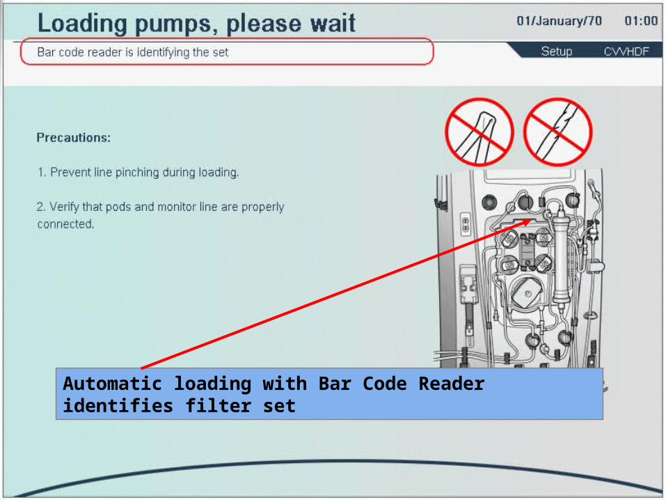
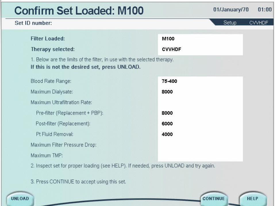
Automatic loading with Bar Code Reader identifies filter set
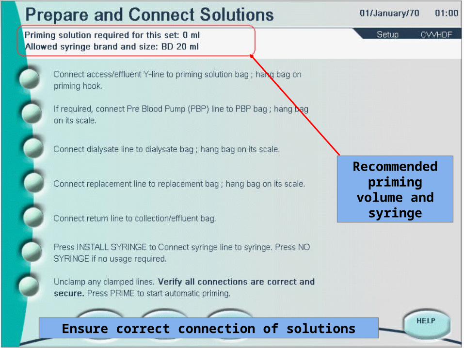
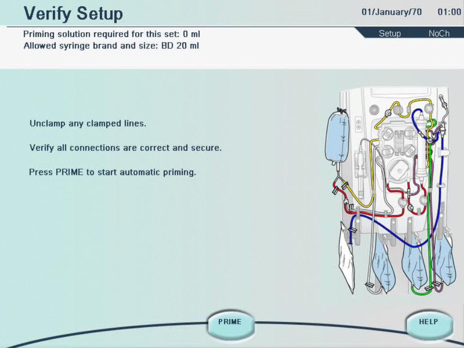
Ensure correct connection of solutions
Recommended priming volume
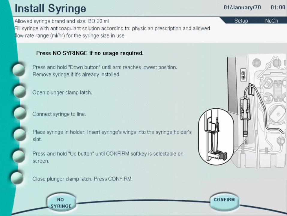
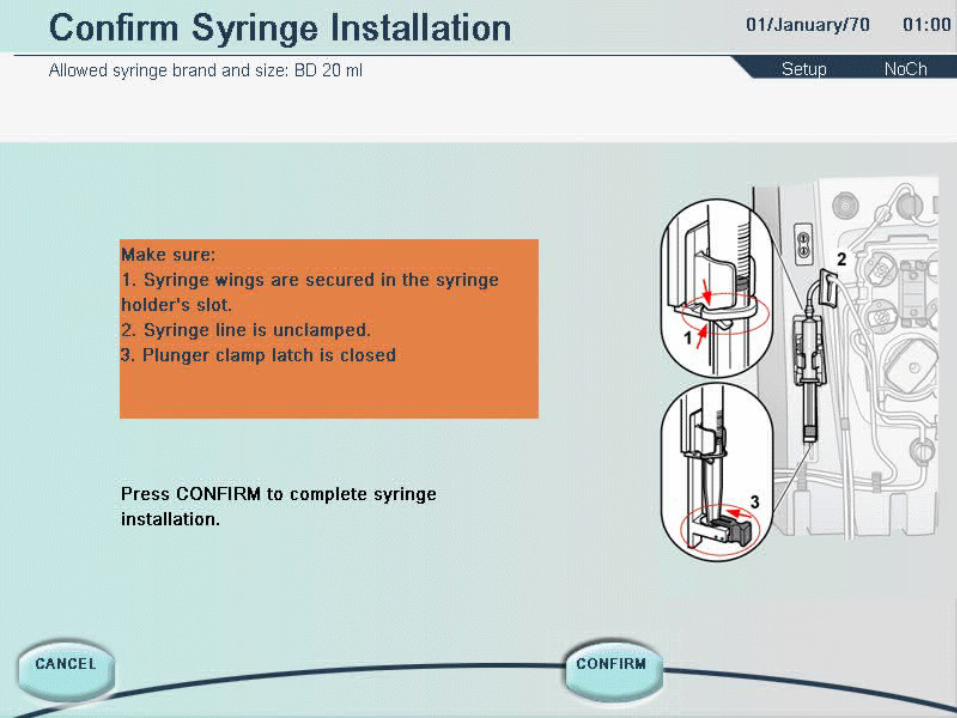
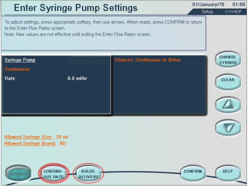
and syringe
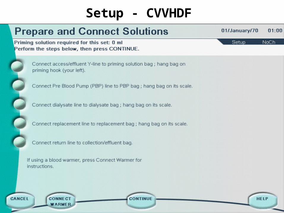
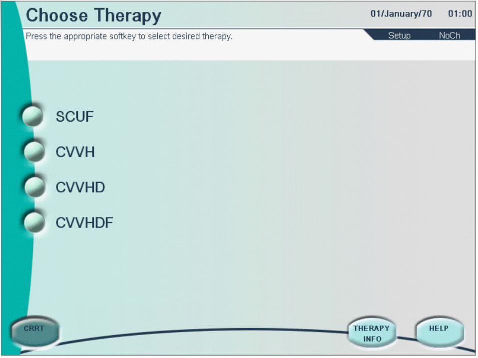
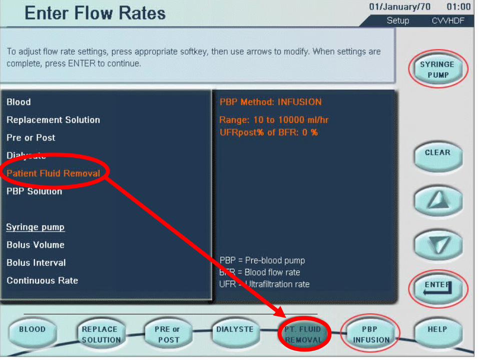
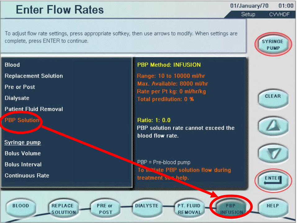
Setup - CVVHDF
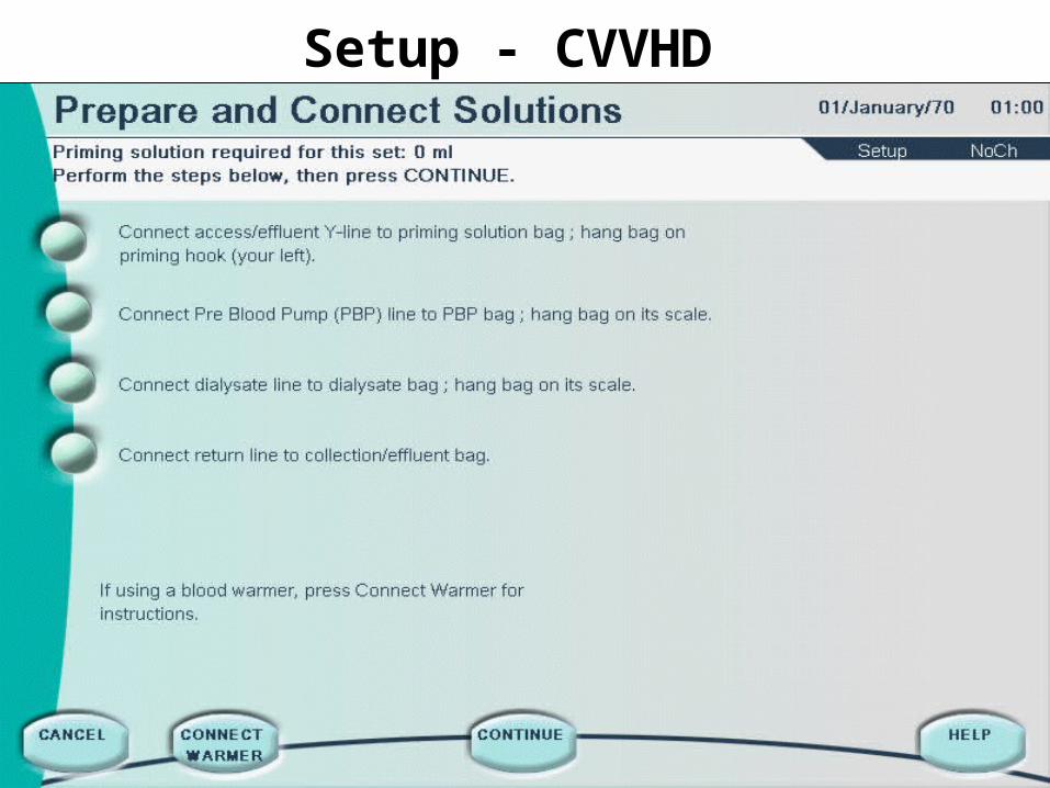
Setup - CVVHD
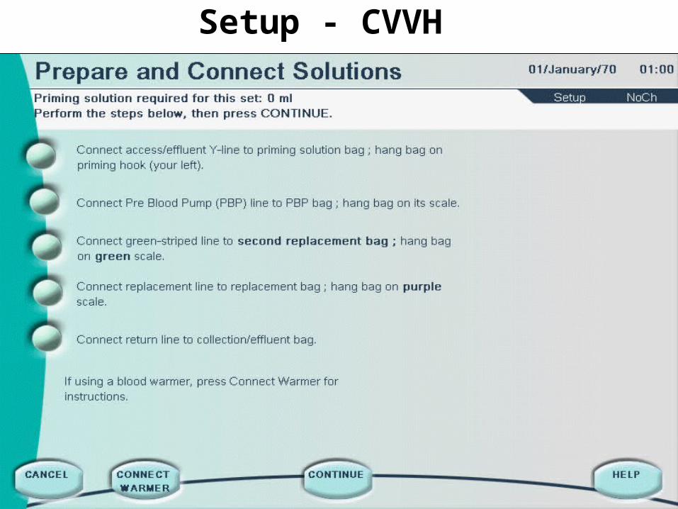
Setup - CVVH
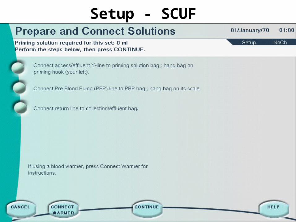
Setup - SCUF
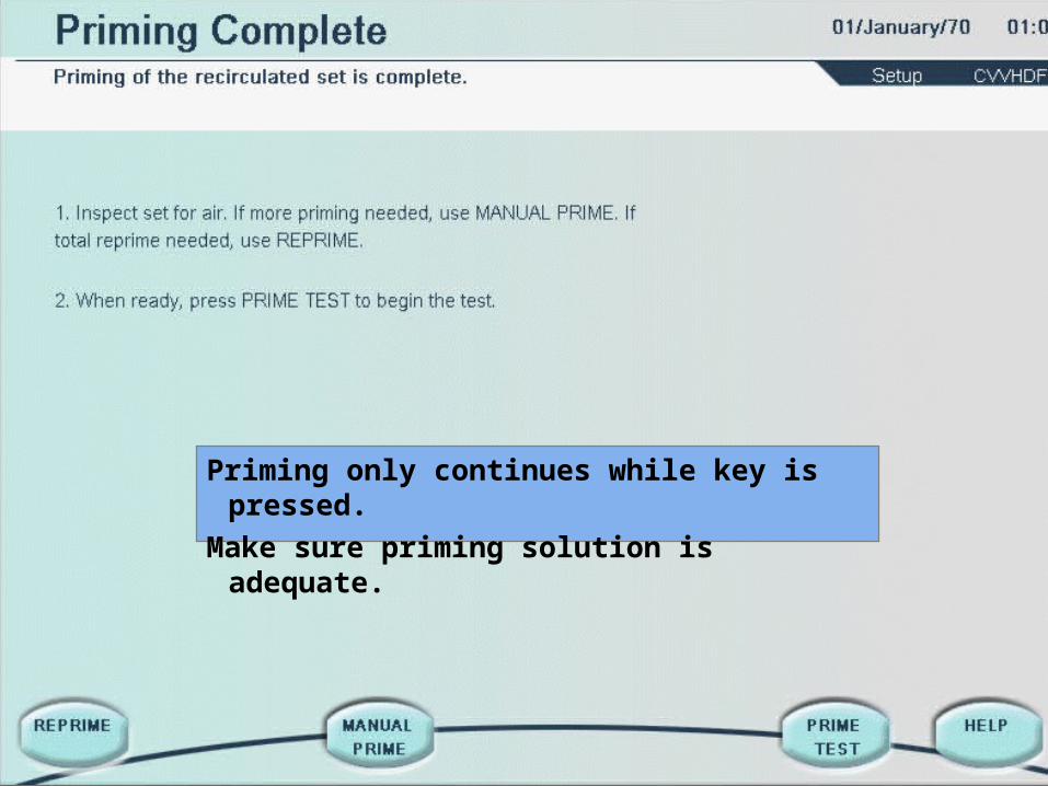
Priming only continues while key is pressed.
Make sure priming solution is adequate.
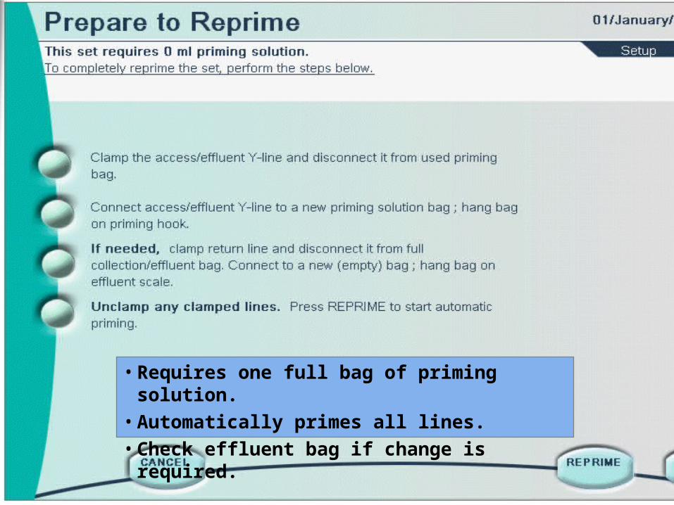
<Insert REPRIME screen>
• Requires one full bag of priming solution. • Automatically primes all lines.• Check effluent bag if change is required.
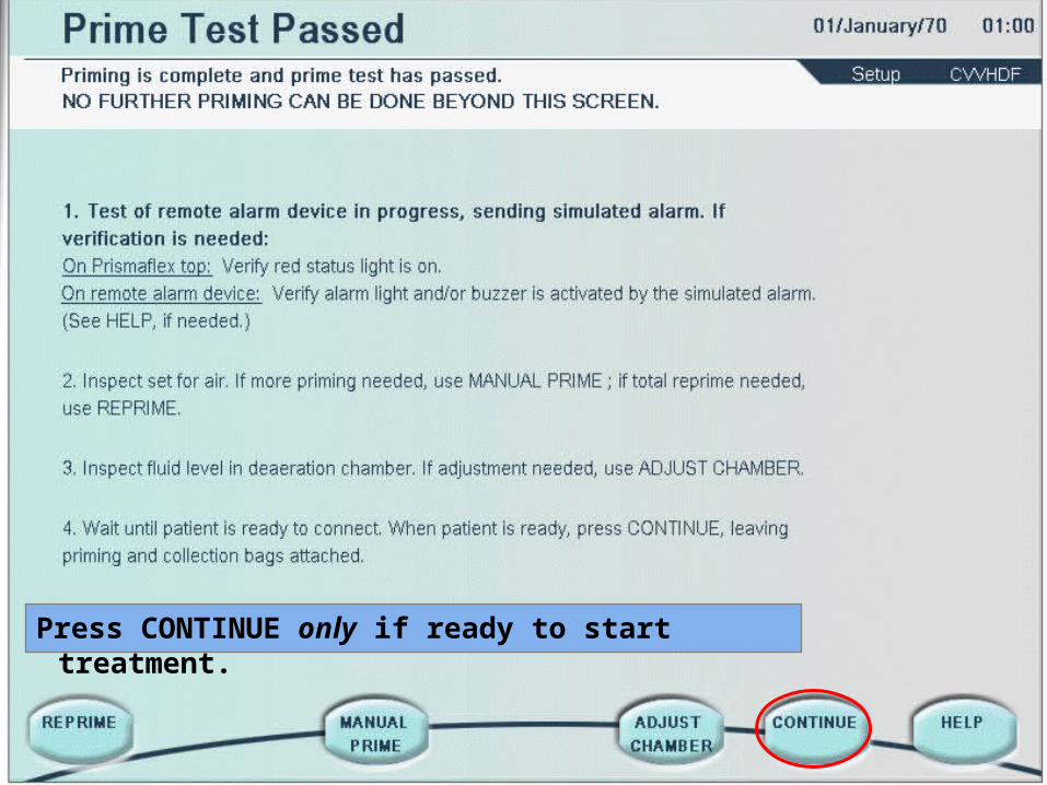
Press CONTINUE only if ready to start treatment.
Prismaflex System
Starting Treatment
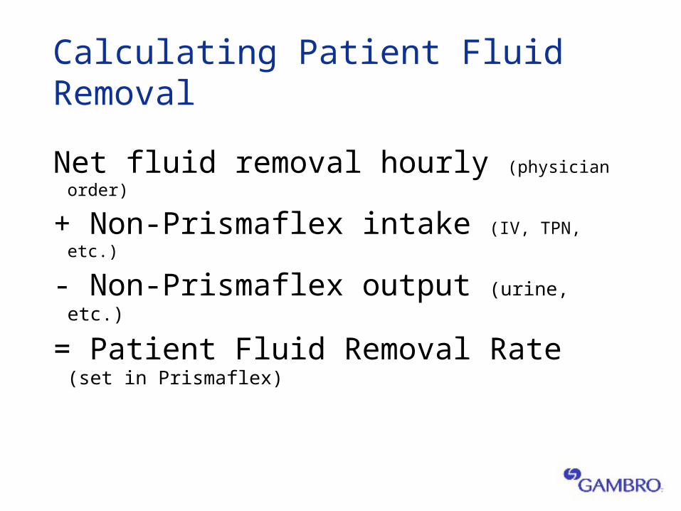
Calculating Patient Fluid Removal
Net fluid removal hourly (physician order)
+ Non-Prismaflex intake (IV, TPN, etc.)
- Non-Prismaflex output (urine, etc.)
= Patient Fluid Removal Rate (set in Prismaflex)
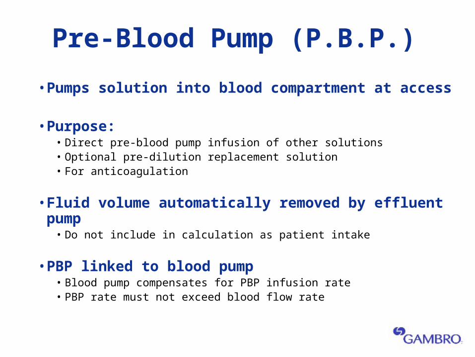
Pre-Blood Pump (P.B.P.)
• Pumps solution into blood compartment at access
• Purpose:• Direct pre-blood pump infusion of other solutions• Optional pre-dilution replacement solution• For anticoagulation
• Fluid volume automatically removed by effluent pump• Do not include in calculation as patient intake
• PBP linked to blood pump• Blood pump compensates for PBP infusion rate• PBP rate must not exceed blood flow rate
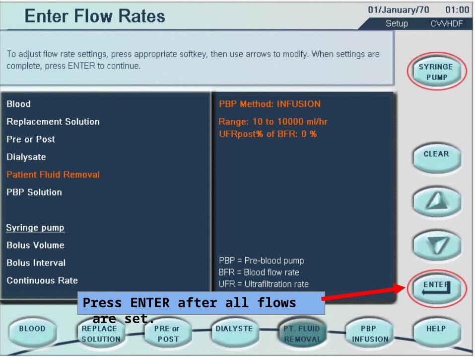
Press ENTER after all flows are set.
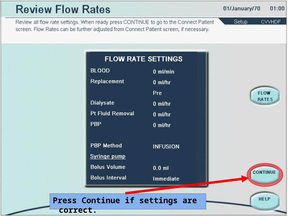
Press Continue if settings are correct.
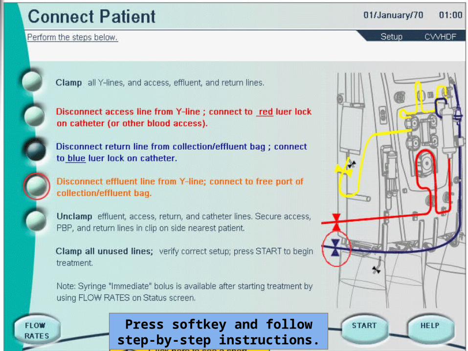
Press softkey and follow step-by-step instructions.
Prismaflex System
Treatment Management
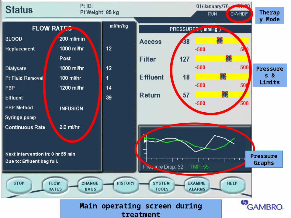
Therapy Mode
Pressures & Limits
Pressure Graphs
Main operating screen during treatment
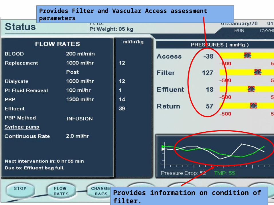
Provides Filter and Vascular Access assessment parameters
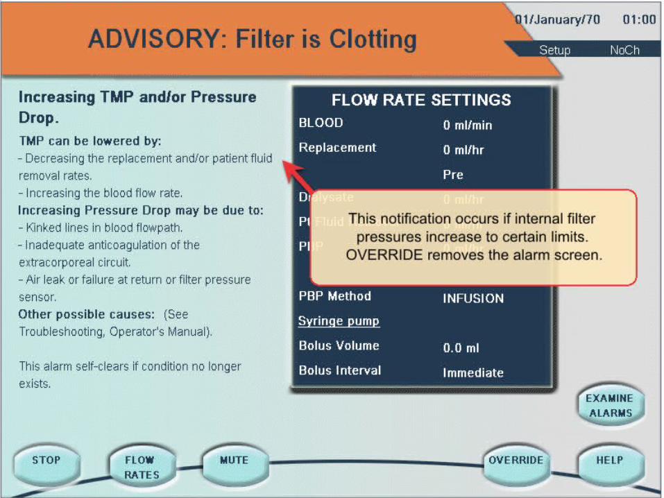
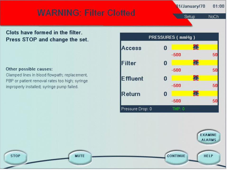
Provides information on condition of filter.
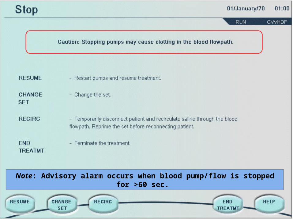
Note: Advisory alarm occurs when blood pump/flow is stopped for >60 sec.
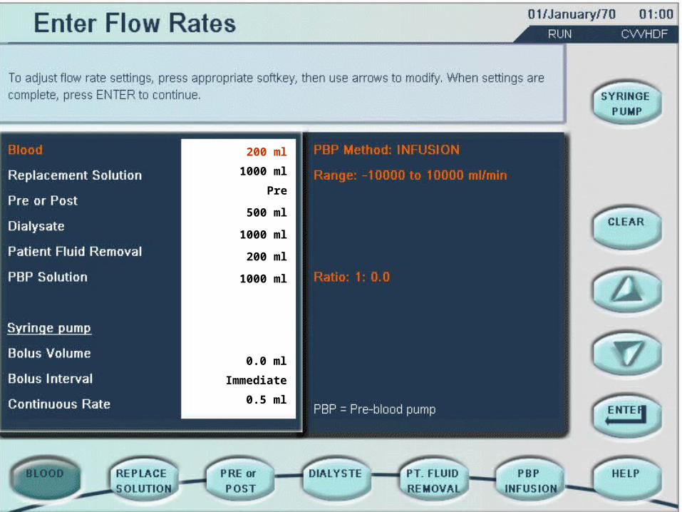
200 ml
1000 ml
Pre
500 ml
1000 ml
200 ml
1000 ml
0.0 ml
Immediate
0.5 ml
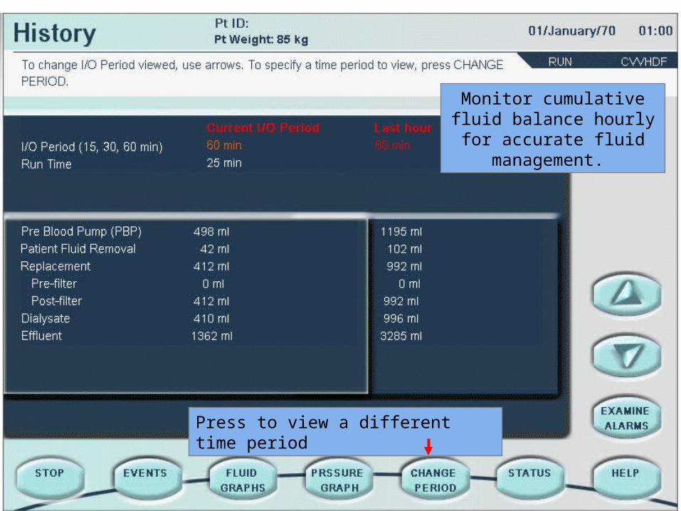
Monitor cumulative fluid balance hourly for accurate
fluid management.
Press to view a different time period
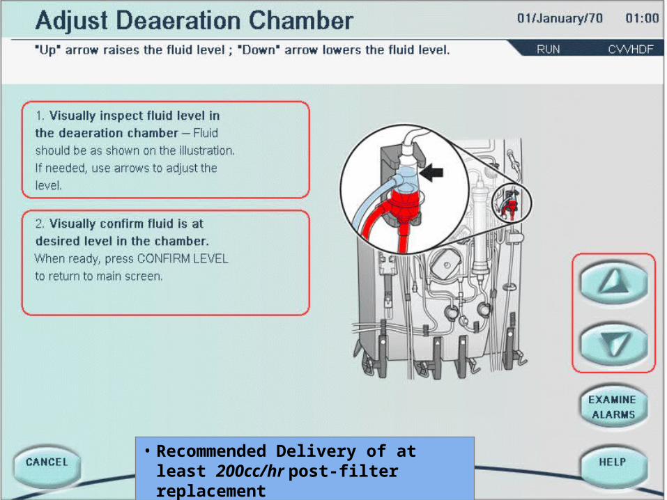
• Recommended Delivery of at least 200cc/hr post-filter replacement
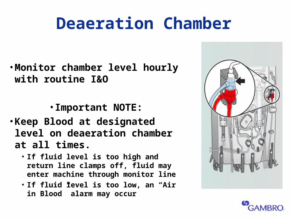
Deaeration Chamber
• Monitor chamber level hourly with routine I&O
• Important NOTE: • Keep Blood at designated level on
deaeration chamber at all times. • If fluid level is too high and return line clamps
off, fluid may enter machine through monitor line
• If fluid level is too low, an “Air in Blood” alarm may occur
Prismaflex System
Basic Alarm Overview
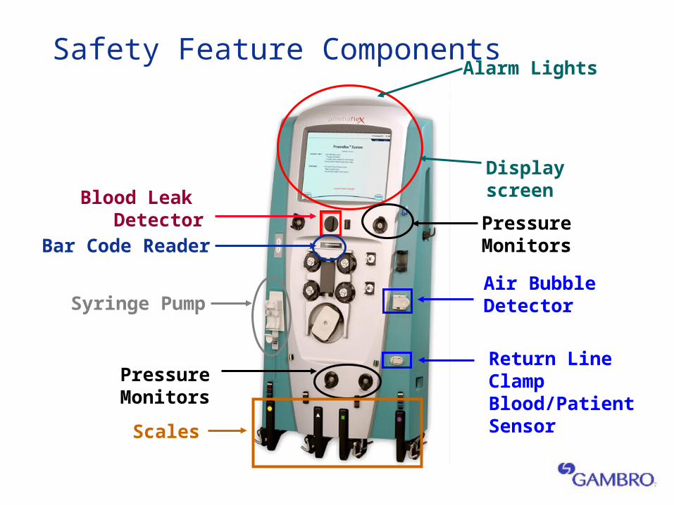
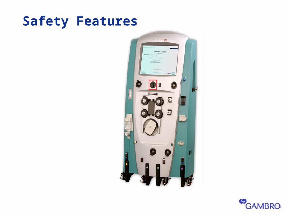
Safety Feature Components
Air Bubble Detector
Blood Leak Detector
Return Line ClampBlood/Patient Sensor
Alarm Lights
Display screen
Pressure Monitors
Scales
Bar Code Reader
Syringe Pump
Pressure Monitors
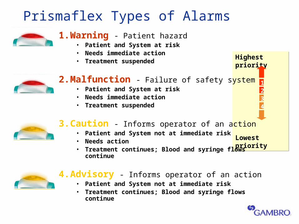
Prismaflex Types of Alarms
Highest priority
Lowest priority
Highest priority
Lowest priority
1234
1. Warning - Patient hazard• Patient and System at risk • Needs immediate action• Treatment suspended
2. Malfunction - Failure of safety system• Patient and System at risk • Needs immediate action• Treatment suspended
3. Caution - Informs operator of an action• Patient and System not at immediate risk• Needs action• Treatment continues; Blood and syringe flows continue
4. Advisory - Informs operator of an action• Patient and System not at immediate risk• Treatment continues; Blood and syringe flows continue

•Read Screen
•Follow Steps
•Check Manual
•Read Screen
•Follow Steps
•Check Manual
The THREE Troubleshooting Commandments
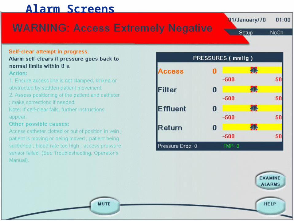
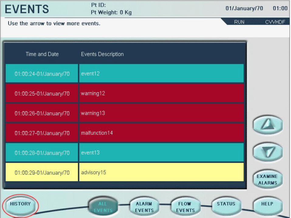
Alarm Screens
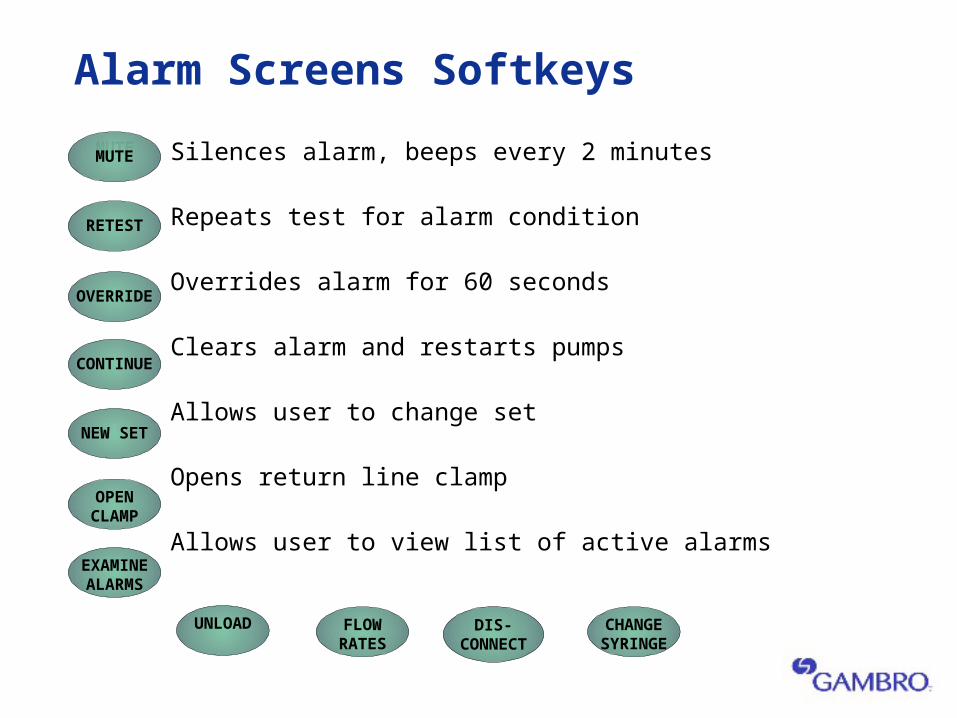
Alarm Screens Softkeys
Silences alarm, beeps every 2 minutes
Repeats test for alarm condition
Overrides alarm for 60 seconds
Clears alarm and restarts pumps
Allows user to change set
Opens return line clamp
Allows user to view list of active alarms
MUTE
OVERRIDE
RETEST
CONTINUE
NEW SET
OPEN CLAMP
EXAMINE ALARMS
UNLOAD FLOW RATES
DIS- CONNECT
CHANGE SYRINGE
MUTE
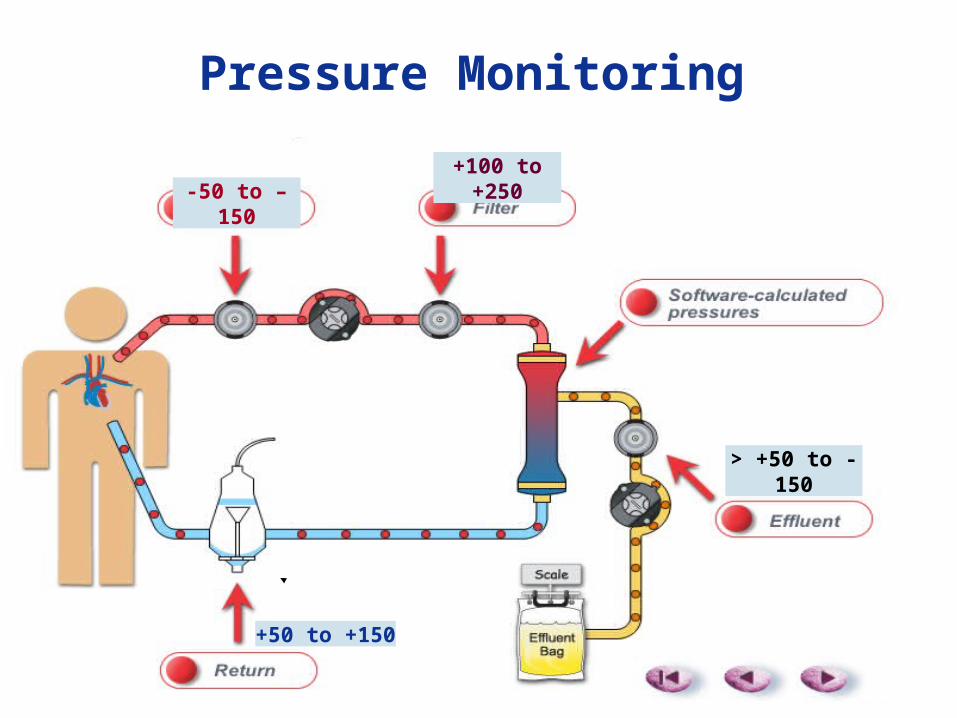
Pressure Monitoring
-50 to –150+100 to +250
> +50 to -150
+50 to +150
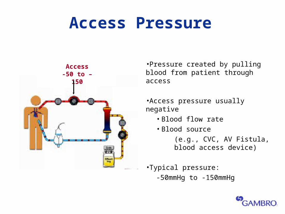
Access Pressure
•Pressure created by pulling blood from patient through access
•Access pressure usually negative • Blood flow rate• Blood source
(e.g., CVC, AV Fistula, blood access device)
•Typical pressure:
-50mmHg to -150mmHg
Access-50 to –150
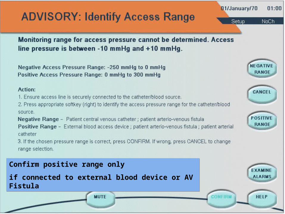
Confirm positive range only
if connected to external blood device or AV Fistula
Confirm positive range only
if connected to external blood device or AV Fistula
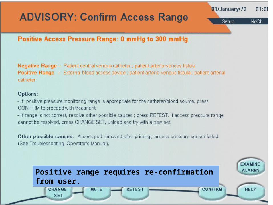
Positive range requires re-confirmation from user. Positive range requires re-confirmation from user.
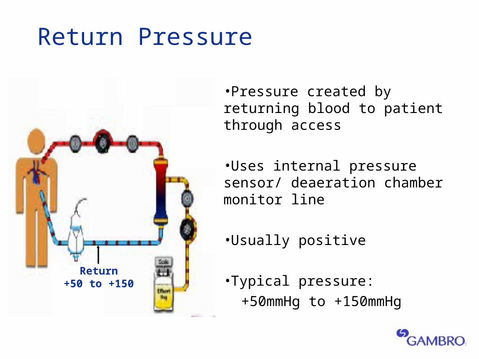
Return Pressure
•Pressure created by returning blood to patient through access
•Uses internal pressure sensor/ deaeration chamber monitor line
•Usually positive
•Typical pressure:
+50mmHg to +150mmHg
Return+50 to +150
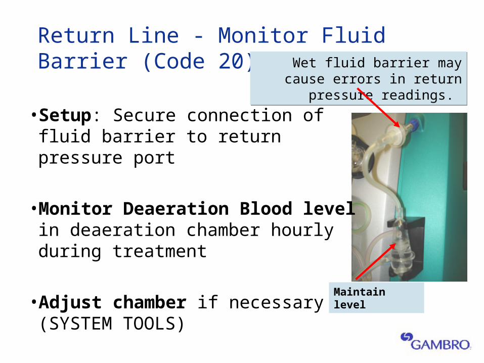
Return Line - Monitor Fluid Barrier (Code 20)
•Setup: Secure connection of fluid barrier to return pressure port
•Monitor Deaeration Blood level in deaeration chamber hourly during treatment
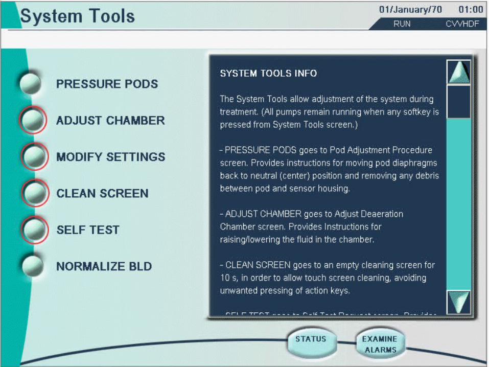
•Adjust chamber if necessary (SYSTEM TOOLS)
Wet fluid barrier may cause errors in return pressure readings.
Wet fluid barrier may cause errors in return pressure readings.
Maintain level
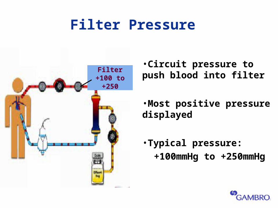
Filter Pressure
•Circuit pressure to push blood into filter
•Most positive pressure displayed
•Typical pressure:
+100mmHg to +250mmHg
Filter+100 to +250
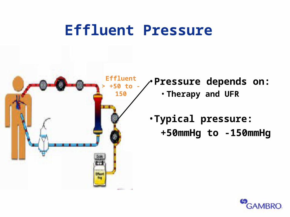
Effluent Pressure
•Pressure depends on:• Therapy and UFR
•Typical pressure:
+50mmHg to -150mmHg
Effluent> +50 to -150

Software Calculated Pressures
Prismaflex
calculates pressures
so you don’t have too!!
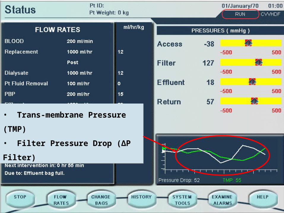
• Trans-membrane Pressure (TMP)
• Filter Pressure Drop (∆P Filter)
• Trans-membrane Pressure (TMP)
• Filter Pressure Drop (∆P Filter)

Trans-Membrane Pressure (TMP)
•Pressure exerted on filter membrane during operation
•Reflects pressure difference between fluid and blood compartments of filter
•Calculated by Prismaflex software
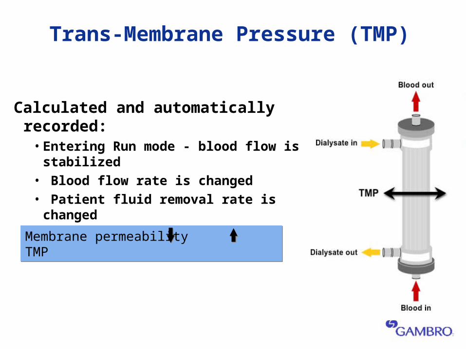
Trans-Membrane Pressure (TMP)
Calculated and automatically recorded:• Entering Run mode - blood flow is stabilized• Blood flow rate is changed• Patient fluid removal rate is changed• Replacement solution rate is changed
Membrane permeability TMP Membrane permeability TMP
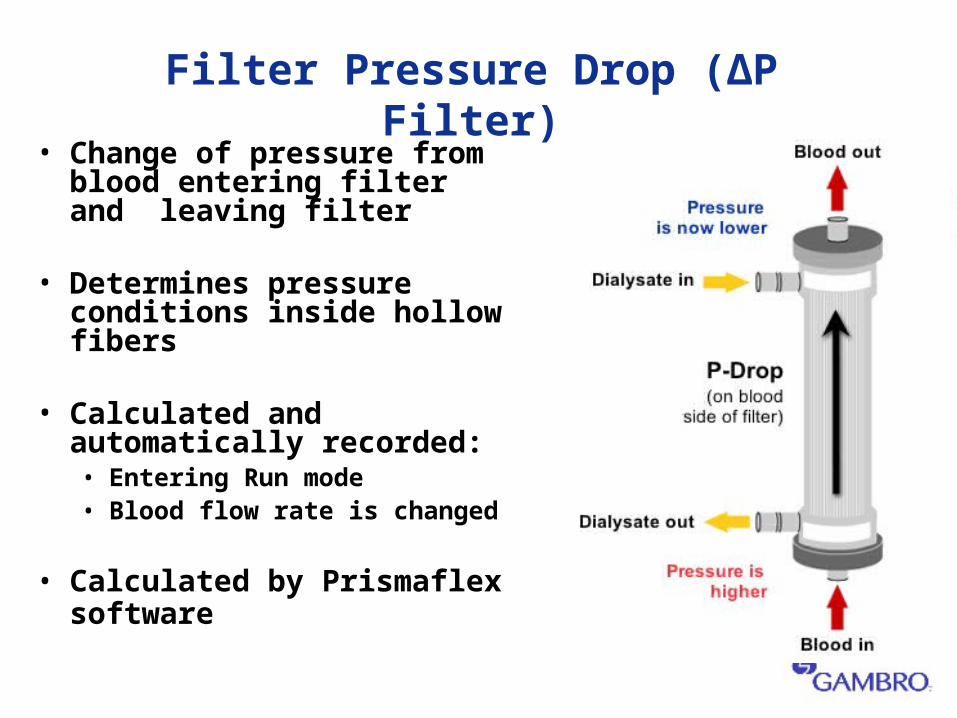
Filter Pressure Drop (ΔP Filter)
• Change of pressure from blood entering filter and leaving filter
• Determines pressure conditions inside hollow fibers
• Calculated and automatically recorded:• Entering Run mode• Blood flow rate is changed
• Calculated by Prismaflex software

Access and Return Pressures
Is it the Vascular Access??
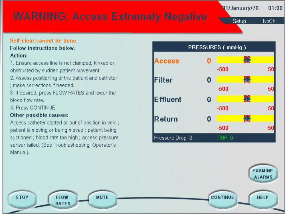

Access Pressure Extremely Negative
Due to vascular access/catheter:• Sitting against vessel wall• Fibrin coating on outside of catheter lumens• Clots on inside of catheter lumens• Size is too small (Adults require 11 Fr or larger)
Other possible causes:• Stopcocks inline with Prismaflex set• Position of patient
Kinking bloodlines• Ensure lines are unclamped
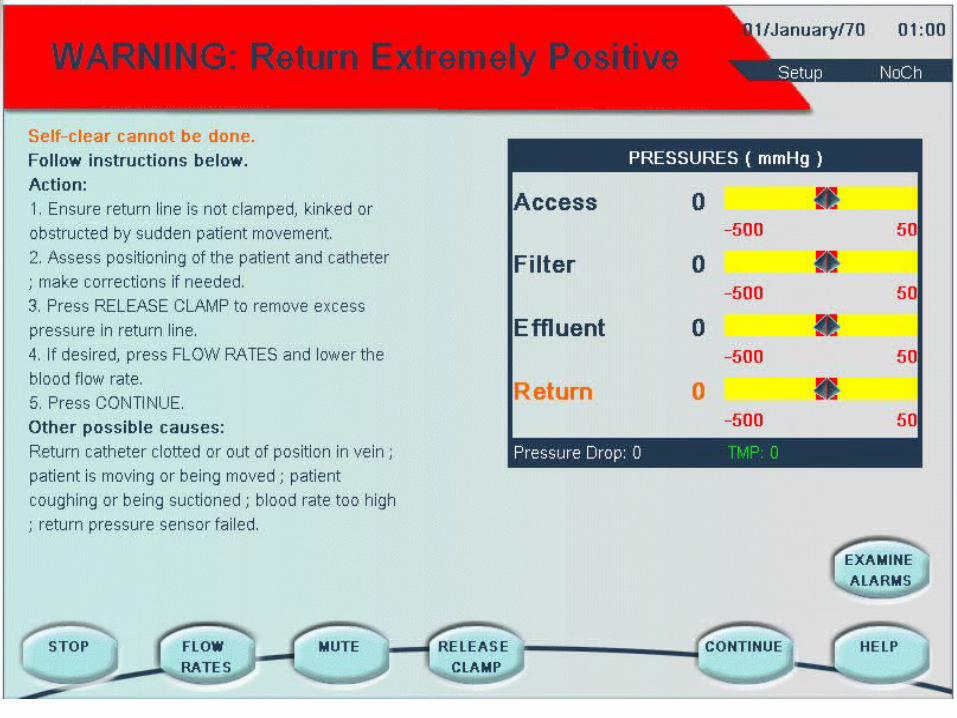
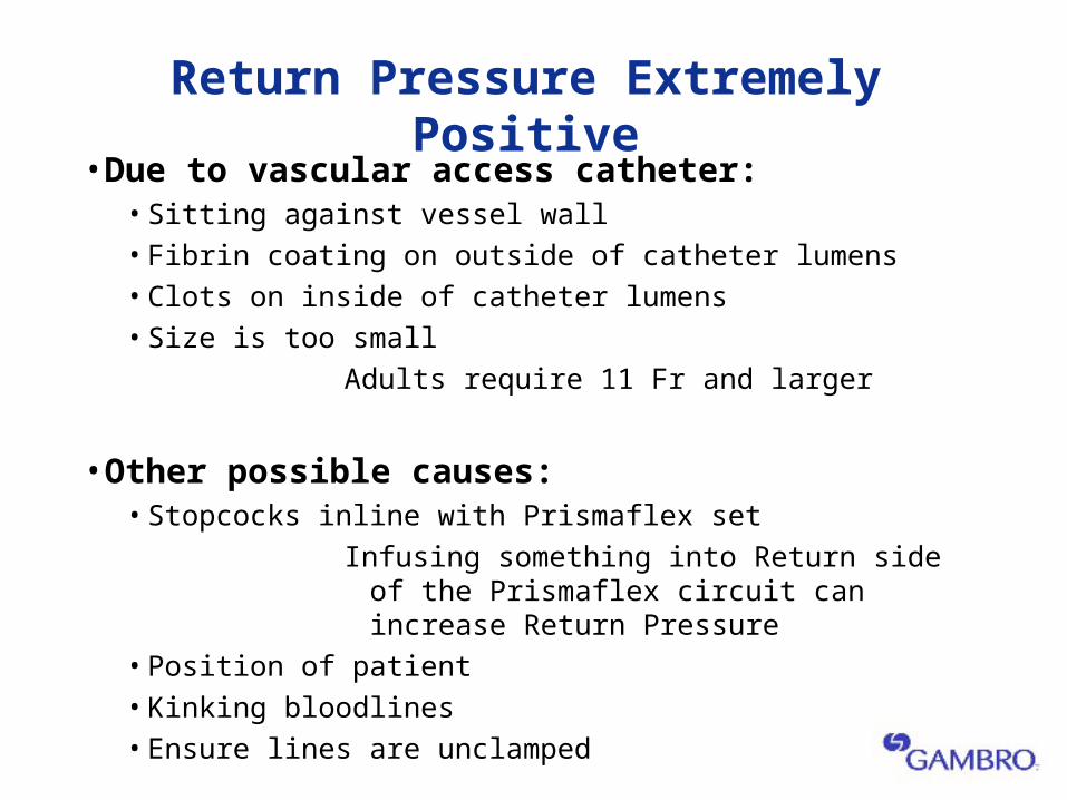
Return Pressure Extremely Positive
• Due to vascular access catheter:• Sitting against vessel wall• Fibrin coating on outside of catheter lumens• Clots on inside of catheter lumens• Size is too small
Adults require 11 Fr and larger
• Other possible causes:• Stopcocks inline with Prismaflex set
Infusing something into Return side of the Prismaflex circuit can increase Return Pressure
• Position of patient• Kinking bloodlines• Ensure lines are unclamped
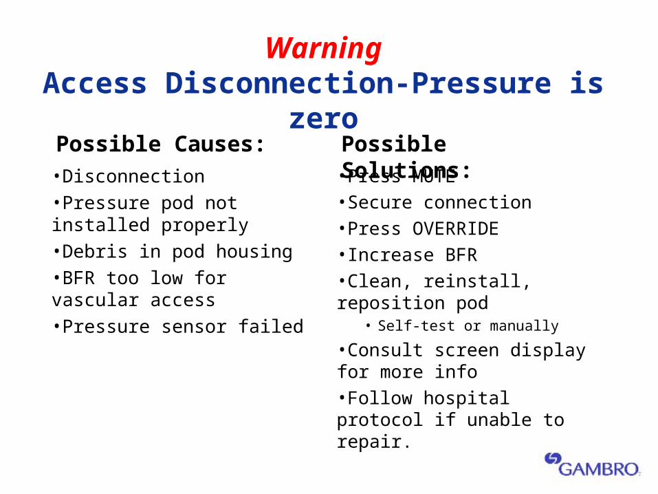
WarningAccess Disconnection-Pressure is zero
•Disconnection•Pressure pod not installed properly•Debris in pod housing•BFR too low for vascular access •Pressure sensor failed
•Press MUTE•Secure connection•Press OVERRIDE•Increase BFR•Clean, reinstall, reposition pod
• Self-test or manually
•Consult screen display for more info•Follow hospital protocol if unable to repair.
Possible Causes: Possible Solutions:
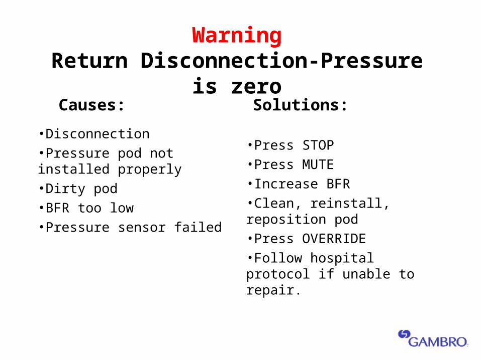
WarningReturn Disconnection-Pressure is zero
•Disconnection•Pressure pod not installed properly •Dirty pod•BFR too low•Pressure sensor failed
•Press STOP•Press MUTE•Increase BFR•Clean, reinstall, reposition pod•Press OVERRIDE•Follow hospital protocol if unable to repair.
Causes: Solutions:
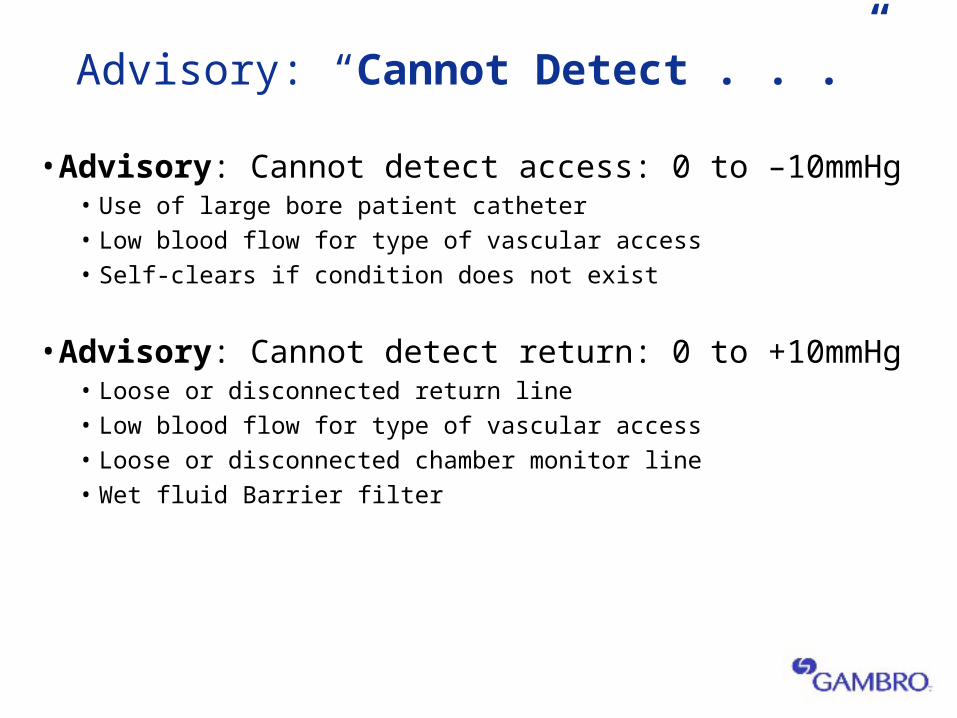
Advisory: “Cannot Detect . . .”
• Advisory: Cannot detect access: 0 to –10mmHg• Use of large bore patient catheter• Low blood flow for type of vascular access• Self-clears if condition does not exist
• Advisory: Cannot detect return: 0 to +10mmHg• Loose or disconnected return line• Low blood flow for type of vascular access• Loose or disconnected chamber monitor line• Wet fluid Barrier filter
Hemofilter Pressures
Is it the Filter??
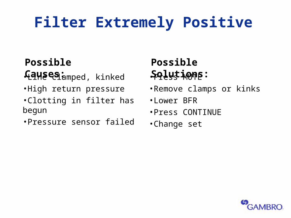
Filter Extremely Positive
•Line clamped, kinked•High return pressure•Clotting in filter has begun•Pressure sensor failed
•Press MUTE•Remove clamps or kinks•Lower BFR•Press CONTINUE•Change set
Possible Causes: Possible Solutions:
Safety Features
Blood Leak Detected (BLD)
• Leakage of blood to the fluid side of the hemofilter
•Other causes:• Air in effluent line• Effluent line not properly installed in BLD• Myoglobin (trauma, burn, Rhabdomyolysis)• Bilirubin (Liver failure, Hyperbilirubin) Conjugated only• Debris in sensor housing
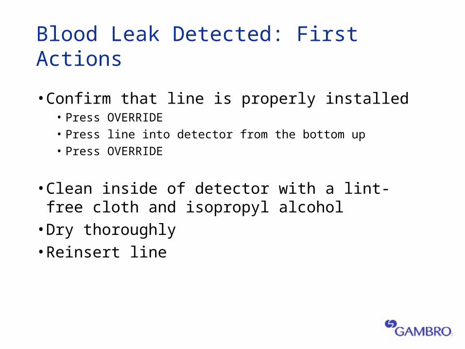
Blood Leak Detected: First Actions
• Confirm that line is properly installed• Press OVERRIDE• Press line into detector from the bottom up• Press OVERRIDE
• Clean inside of detector with a lint-free cloth and isopropyl alcohol• Dry thoroughly• Reinsert line
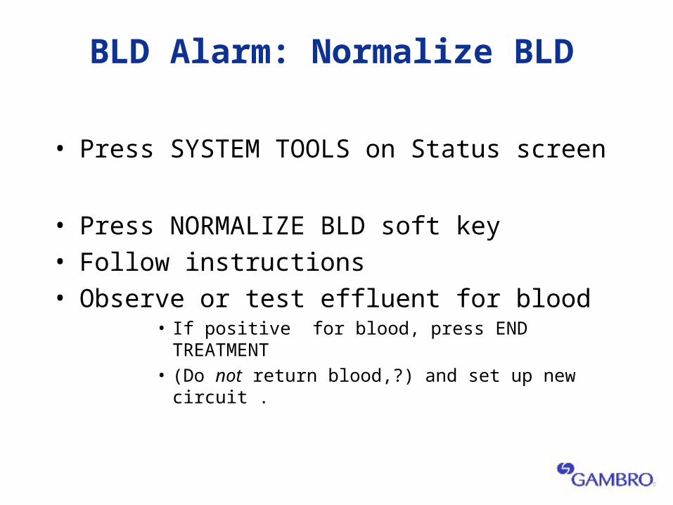
BLD Alarm: Normalize BLD
• Press SYSTEM TOOLS on Status screen
• Press NORMALIZE BLD soft key • Follow instructions• Observe or test effluent for blood
• If positive for blood, press END TREATMENT • (Do not return blood,?) and set up new circuit .
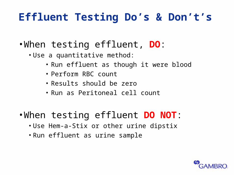
Effluent Testing Do’s & Don’t’s
•When testing effluent, DO:• Use a quantitative method:
• Run effluent as though it were blood• Perform RBC count• Results should be zero• Run as Peritoneal cell count
•When testing effluent DO NOT:• Use Hem-a-Stix or other urine dipstix• Run effluent as urine sample
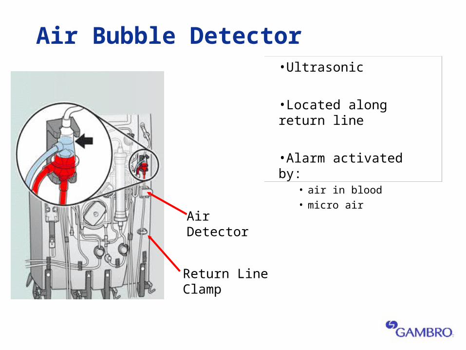
Air Bubble Detector•Ultrasonic
•Located along return line
•Alarm activated by:• air in blood• micro air
Air Detector
Return Line Clamp
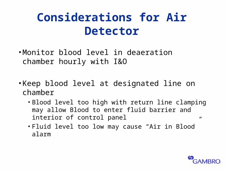
Considerations for Air Detector
• Monitor blood level in deaeration chamber hourly with I&O
• Keep blood level at designated line on chamber• Blood level too high with return line clamping may allow Blood
to enter fluid barrier and interior of control panel • Fluid level too low may cause “Air in Blood” alarm
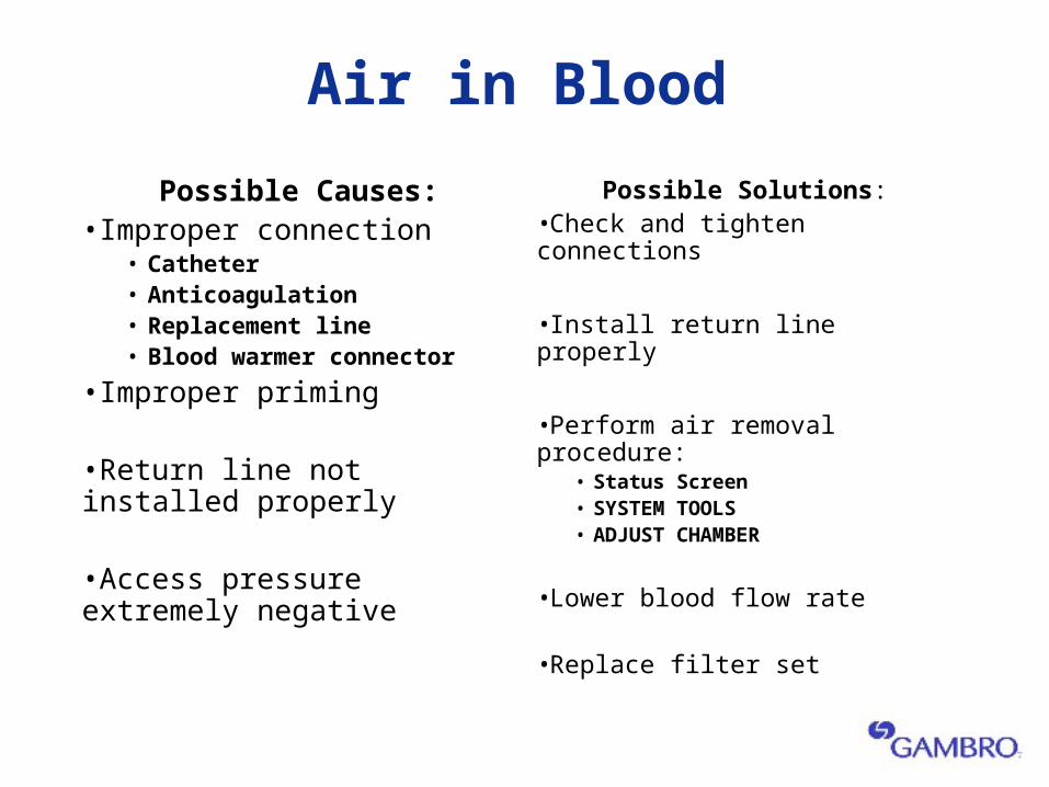
Air in Blood
Possible Causes:•Improper connection
• Catheter• Anticoagulation• Replacement line• Blood warmer connector
•Improper priming
•Return line not installed properly
•Access pressure extremely negative
Possible Solutions:•Check and tighten connections
•Install return line properly
•Perform air removal procedure:• Status Screen• SYSTEM TOOLS • ADJUST CHAMBER
•Lower blood flow rate
•Replace filter set
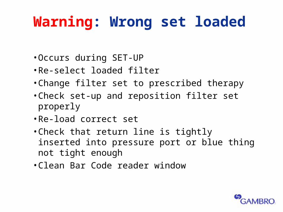
Warning: Wrong set loaded
• Occurs during SET-UP• Re-select loaded filter• Change filter set to prescribed therapy• Check set-up and reposition filter set properly• Re-load correct set• Check that return line is tightly inserted into
pressure port or blue thing not tight enough• Clean Bar Code reader window
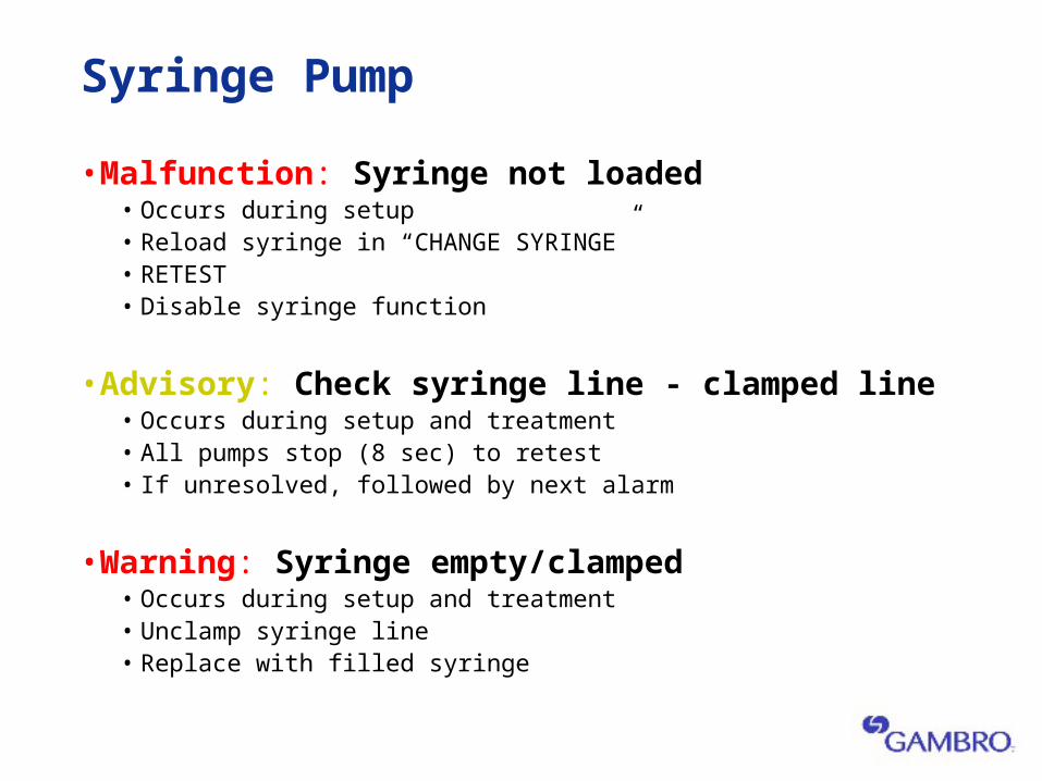
Syringe Pump
• Malfunction: Syringe not loaded• Occurs during setup• Reload syringe in “CHANGE SYRINGE”• RETEST• Disable syringe function
• Advisory: Check syringe line - clamped line• Occurs during setup and treatment• All pumps stop (8 sec) to retest• If unresolved, followed by next alarm
• Warning: Syringe empty/clamped• Occurs during setup and treatment• Unclamp syringe line• Replace with filled syringe
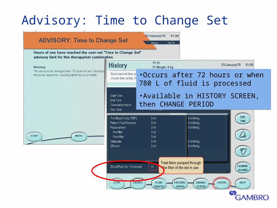
Advisory: Time to Change Set
•Occurs after 72 hours or when 780 L of fluid is processed
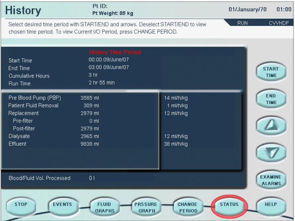
•Available in HISTORY SCREEN, then CHANGE PERIOD
•Occurs after 72 hours or when 780 L of fluid is processed
•Available in HISTORY SCREEN, then CHANGE PERIOD
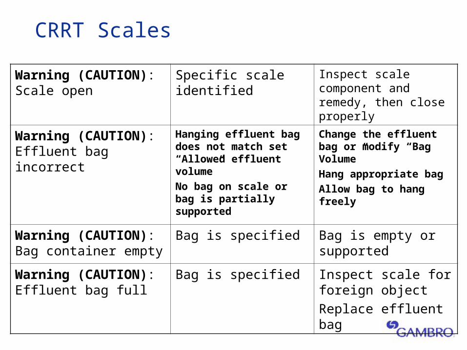
CRRT Scales
Warning (CAUTION): Scale open
Specific scale identified
Inspect scale component and remedy, then close properly
Warning (CAUTION): Effluent bag incorrect
Hanging effluent bag does not match set “Allowed effluent volume”
No bag on scale or bag is partially supported
Change the effluent bag or modify “Bag Volume”
Hang appropriate bag
Allow bag to hang freely
Warning (CAUTION): Bag container empty
Bag is specified Bag is empty or supported
Warning (CAUTION): Effluent bag full
Bag is specified Inspect scale for foreign object
Replace effluent bag
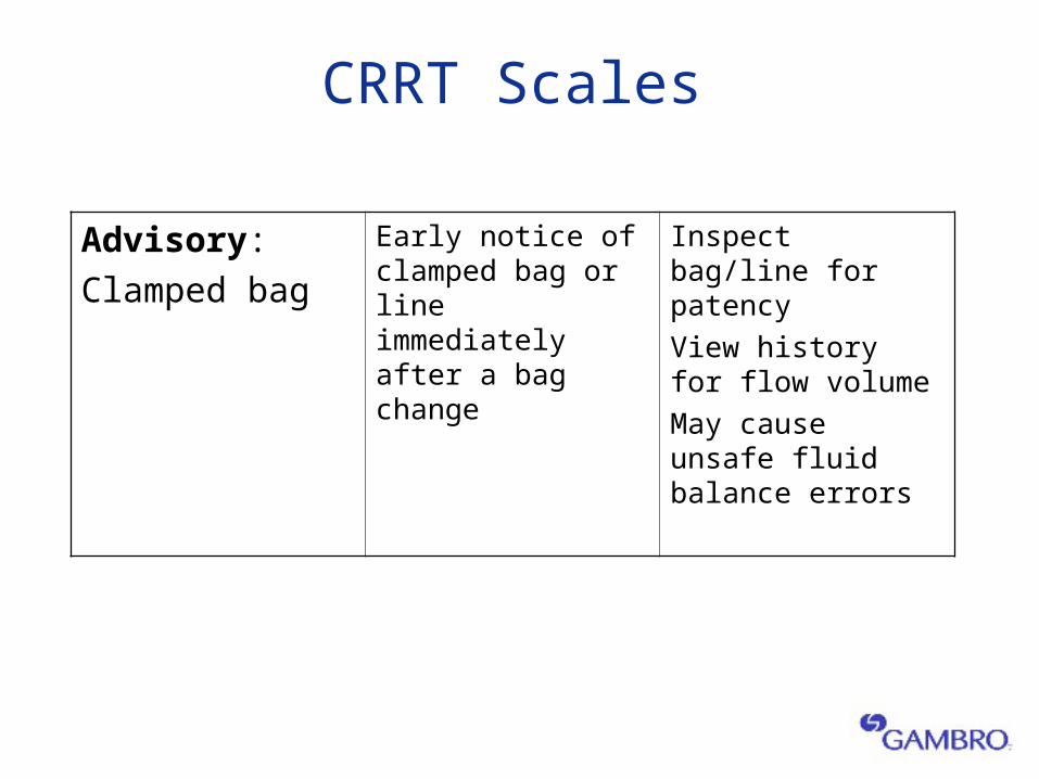
CRRT Scales
Advisory:
Clamped bag
Early notice of clamped bag or line immediately after a bag change
Inspect bag/line for patency
View history for flow volume
May cause unsafe fluid balance errors
®
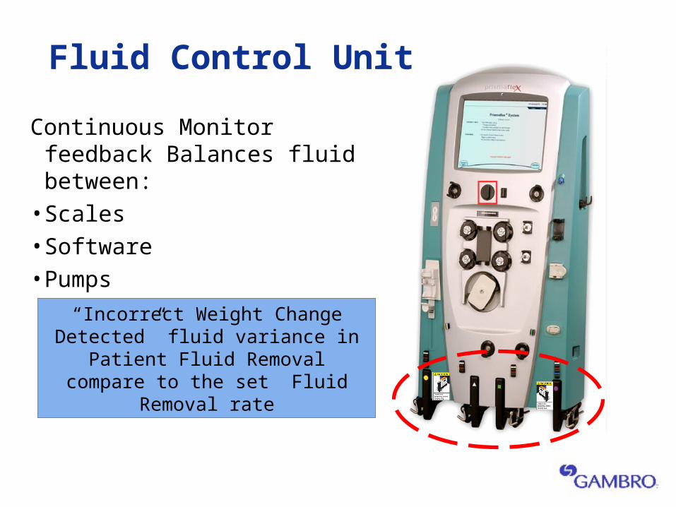
Fluid Control Unit
Continuous Monitor feedback Balances fluid between:• Scales• Software • Pumps
“Incorrect Weight Change Detected” fluid variance in Patient Fluid Removal
compare to the set Fluid Removal rate
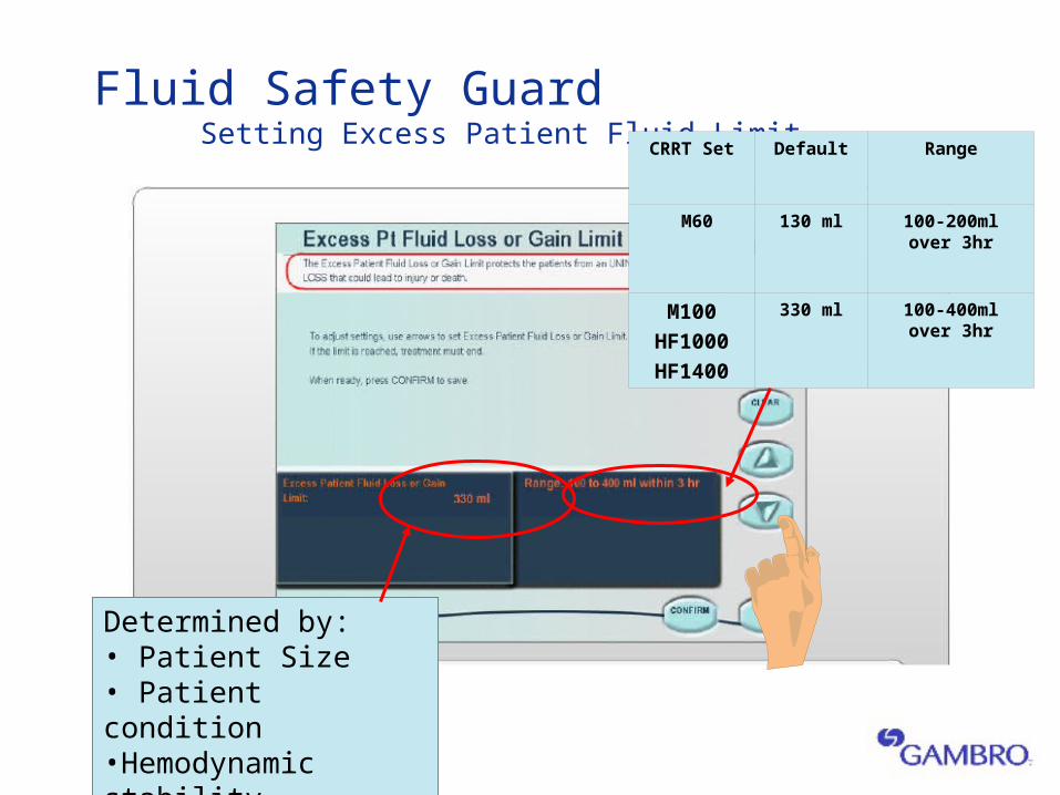
Determined by:• Patient Size• Patient condition•Hemodynamic stability
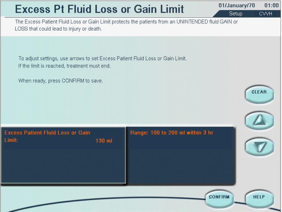
Fluid Safety Guard Setting Excess Patient Fluid Limit
CRRT Set Default Range
M60 130 ml 100-200ml over 3hr
M100
HF1000
HF1400
330 ml 100-400ml over 3hr
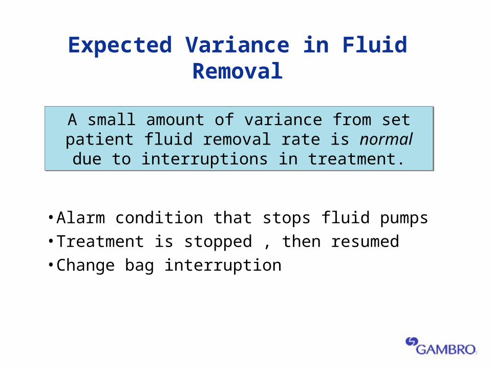
Expected Variance in Fluid Removal
• Alarm condition that stops fluid pumps • Treatment is stopped , then resumed• Change bag interruption
A small amount of variance from set patient fluid removal rate is normal due to interruptions in
treatment.
A small amount of variance from set patient fluid removal rate is normal due to interruptions in
treatment.
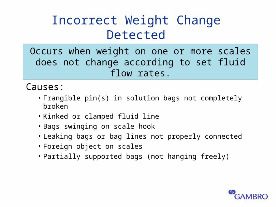
Incorrect Weight Change Detected
Causes:• Frangible pin(s) in solution bags not completely broken• Kinked or clamped fluid line• Bags swinging on scale hook• Leaking bags or bag lines not properly connected• Foreign object on scales• Partially supported bags (not hanging freely)
Occurs when weight on one or more scales does not change according to set fluid flow rates.
Occurs when weight on one or more scales does not change according to set fluid flow rates.
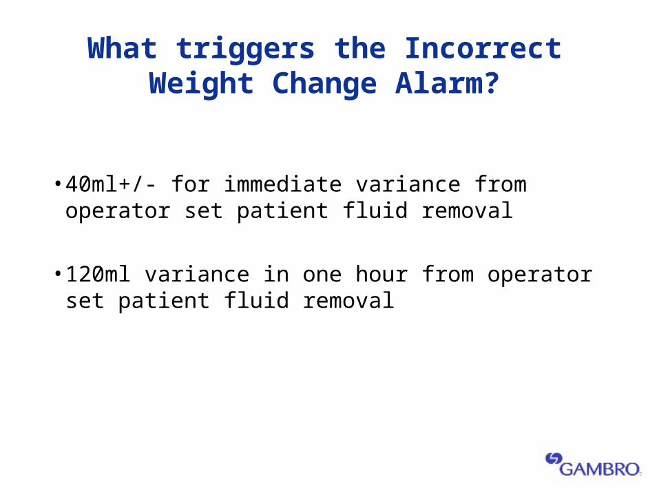
What triggers the Incorrect Weight Change Alarm?
• 40ml+/- for immediate variance from operator set patient fluid removal
• 120ml variance in one hour from operator set patient fluid removal
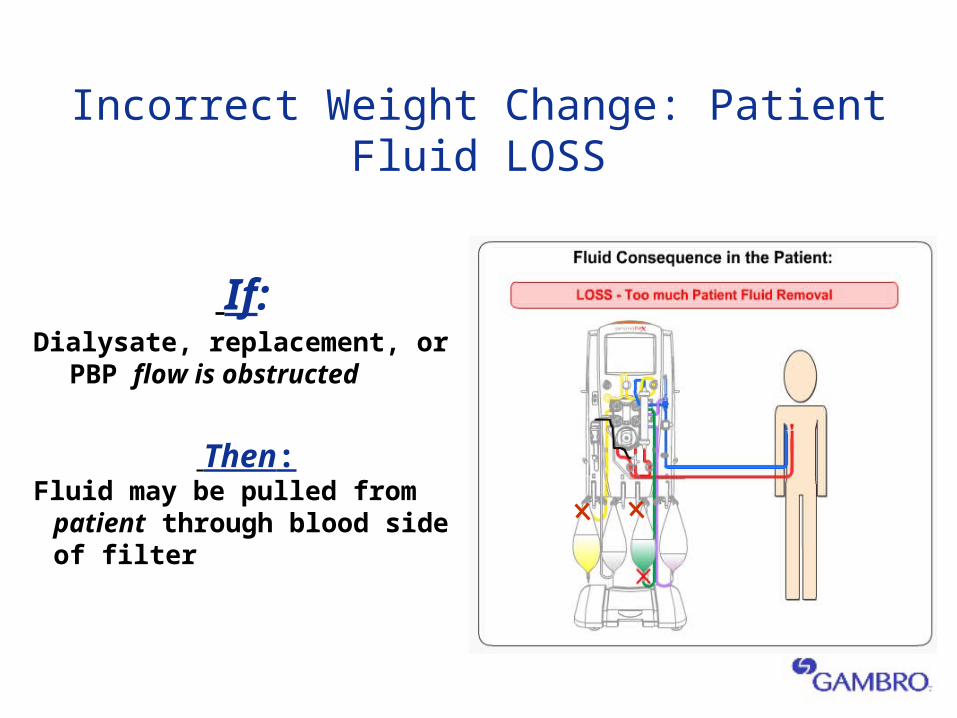
Incorrect Weight Change: Patient Fluid LOSS
If: Dialysate, replacement, or PBP
flow is obstructed
Then:Fluid may be pulled from patient
through blood side of filter
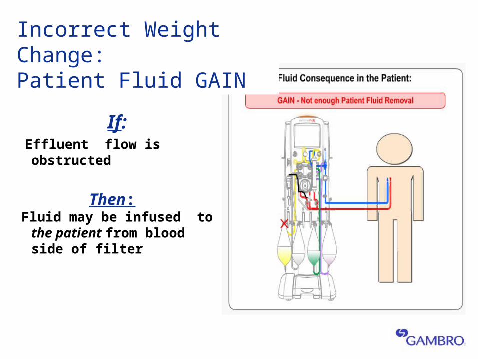
Incorrect Weight Change: Patient Fluid GAIN
If: Effluent flow is obstructed
Then: Fluid may be infused to the
patient from blood side of filter
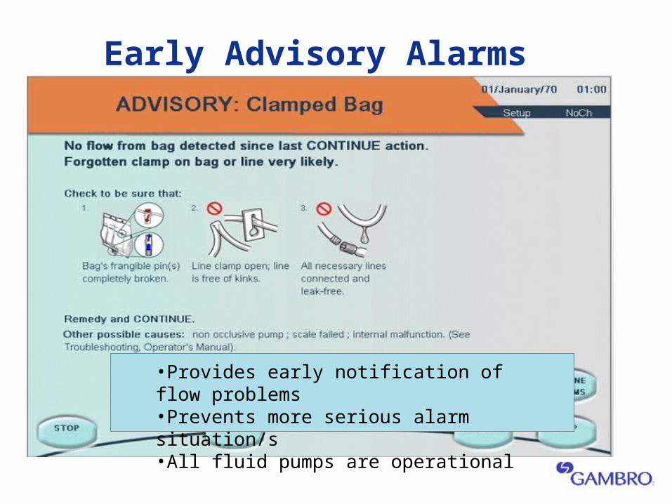
Early Advisory Alarms
•Provides early notification of flow problems•Prevents more serious alarm situation/s•All fluid pumps are operational
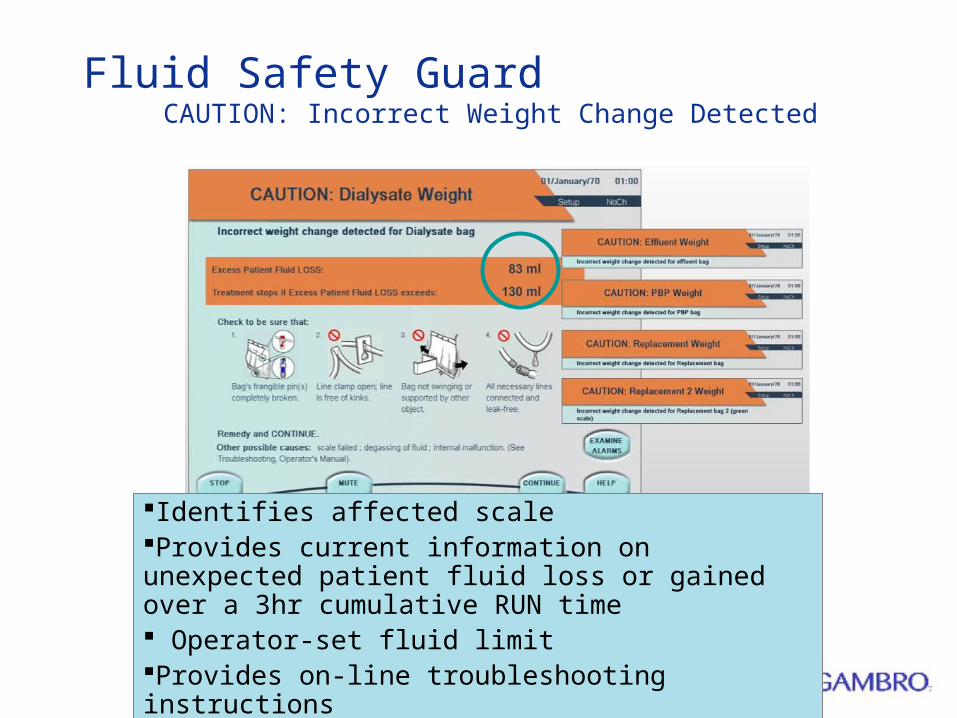
Fluid Safety Guard CAUTION: Incorrect Weight Change Detected
Identifies affected scaleProvides current information on unexpected patient fluid loss or gained over a 3hr cumulative RUN time Operator-set fluid limitProvides on-line troubleshooting instructions
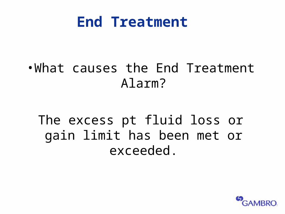
End Treatment
•What causes the End Treatment Alarm?
The excess pt fluid loss or gain limit has been met or exceeded.
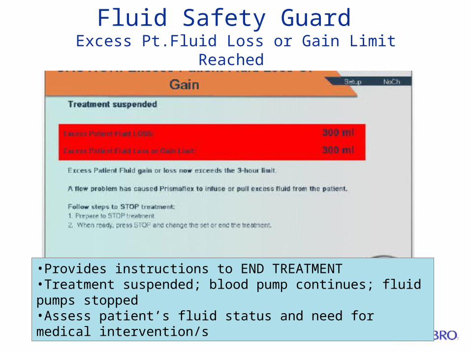
Fluid Safety Guard Excess Pt.Fluid Loss or Gain Limit Reached
•Provides instructions to END TREATMENT•Treatment suspended; blood pump continues; fluid pumps stopped•Assess patient’s fluid status and need for medical intervention/s
References and Further Reading
•Prismaflex Operator Manual •Prismaflex Tutorial•Prismaflex Training Guide Software v3.20

QUESTIONS?
Prismaflex System
End Treatment
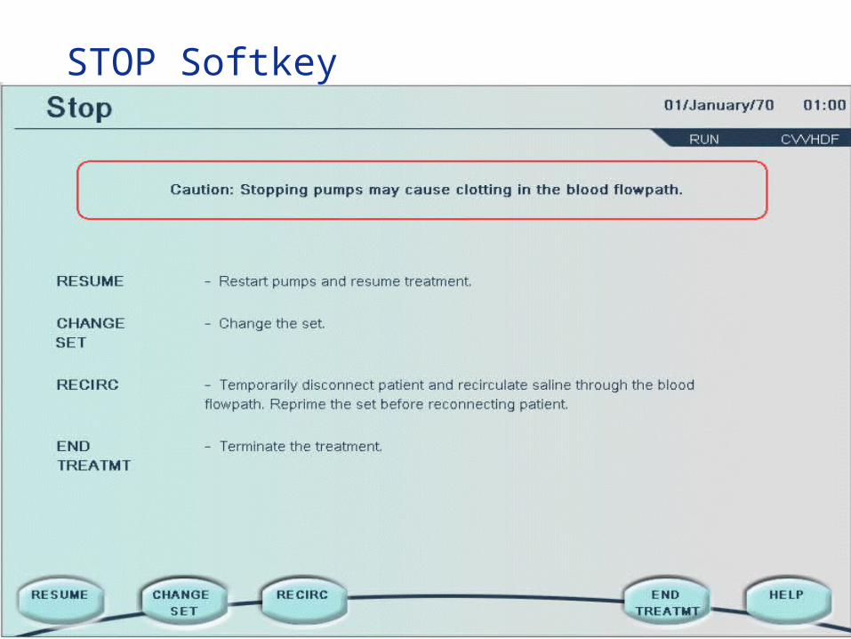
STOP Softkey
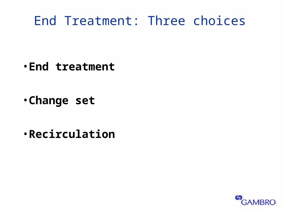
End Treatment: Three choices
•End treatment
•Change set
•Recirculation
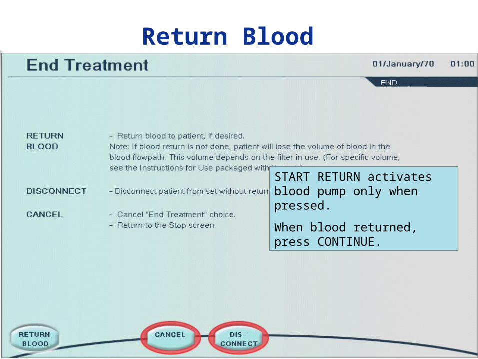
Return Blood
START RETURN activates blood pump only when pressed.
When blood returned, press CONTINUE.
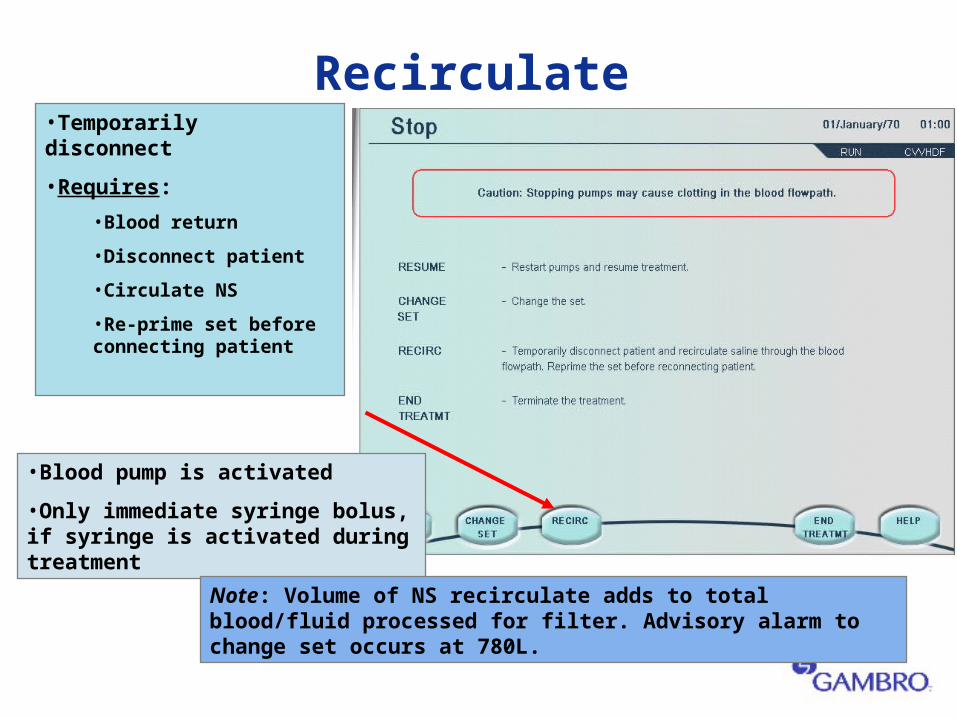
Recirculate•Temporarily disconnect
•Requires:
•Blood return
•Disconnect patient
•Circulate NS
•Re-prime set before connecting patient
•Blood pump is activated
•Only immediate syringe bolus, if syringe is activated during treatment
Note: Volume of NS recirculate adds to total blood/fluid processed for filter. Advisory alarm to change set occurs at 780L.
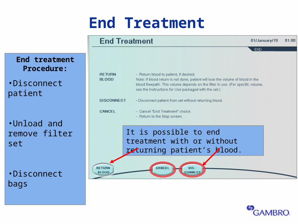
End treatment Procedure:
•Disconnect patient
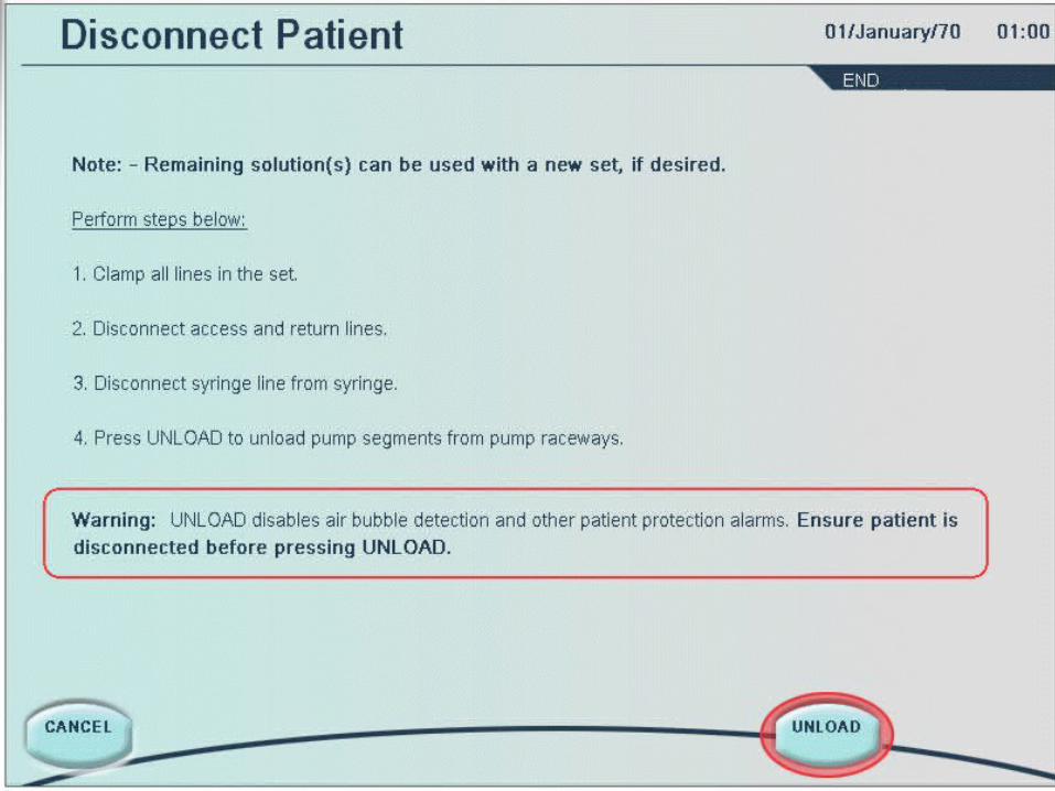
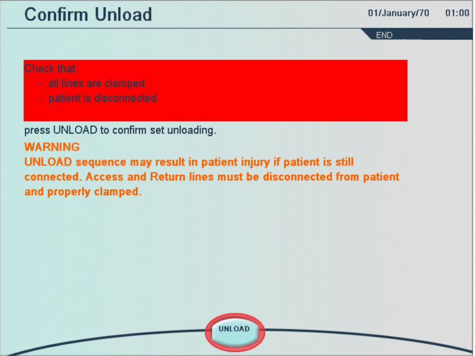
•Unload and remove filter set
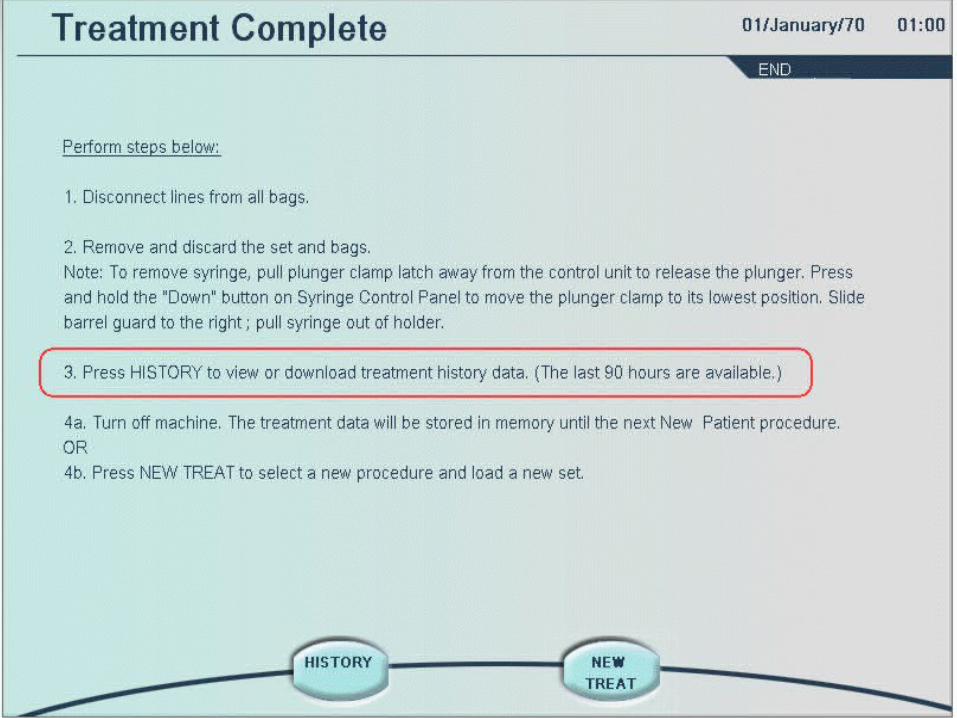
•Disconnect bags
It is possible to end treatment with or without returning patient’s blood.
End Treatment

Gambro is here to assist you 24 hours a day7 days a week:1-800-525-2623

References and Further Reading
•Prismaflex Operator Manual •Prismaflex Tutorial