3-rd workshop of women project rome january 19-th, 2007 university of rome “sapienza”, infocom...
TRANSCRIPT

3-rd Workshop3-rd Workshop of of WOMEN WOMEN ProjectProjectRome January 19-th, 2007
University of Rome “Sapienza”, INFOCOM Dept. (Faculty of Engineering)
Wireless Mesh Networks:Wireless Mesh Networks:
First part:First part:
Point to point links ofPoint to point links ofwireless mesh nodes based on wireless mesh nodes based on
MIMO UWB-IR technologyMIMO UWB-IR technology

Outline
System model: main characteristics
Performance of the MIMO UWB-IR Co-Decoder
Derivation of the MIMO UWB-IR Co-Decoder
Conclusions
Main aspects of the MIMO UWB-IR Synchronizer

NON-COHERENT NON-COHERENT ML ML
SYNCHRONIZERSYNCHRONIZER
PILOT SIGNALPILOT SIGNAL GENERATOR GENERATOR
FORFOR SYNCHRONISMSYNCHRONISM
RECOVERYRECOVERY
MIMO UWB-IR System Model(with Poisson distributed multipath fading)
1(1)
0
( ) ( )SN
pilot S Wm
x t E s t mT
0, . . .[ ]V
1( )
0
( ) / ( )fN
idata f t f i p
m
UWB IR M OPPM data signal
x t E N p t mT d T
1 0
( ) (( , ) )( )tN
j ji
data signal measured at j thantenna
n
V
n in
h j iy t x w tt
ji0
r t
( ) ( j,i) ( ) ,
1 j N , 1 i N
V
n nn
h t h t
1
rN
j
tN
111( )h t
rN 1( )h t
j1( )h t
t1N ( )h t
r tN N ( )h t
ji0
r t
( ) ( j,i) ( ) ,
1 j N , 1 i N
V
n nn
h t h t
(1)
0
( ,( ) ( ) ( )) j
data signal measured at
j pilo
j t
V
n
han
n
t a
t
en
n
n
h j ir t x t w t
SPACE-TIME CODED SPACE-TIME CODED PACKET TRANSMITTERPACKET TRANSMITTER
ADOPTING OPPMADOPTING OPPMMODULATION FORMAT MODULATION FORMAT
NON-COHERENT NON-COHERENT ML ML
DECODERDECODER
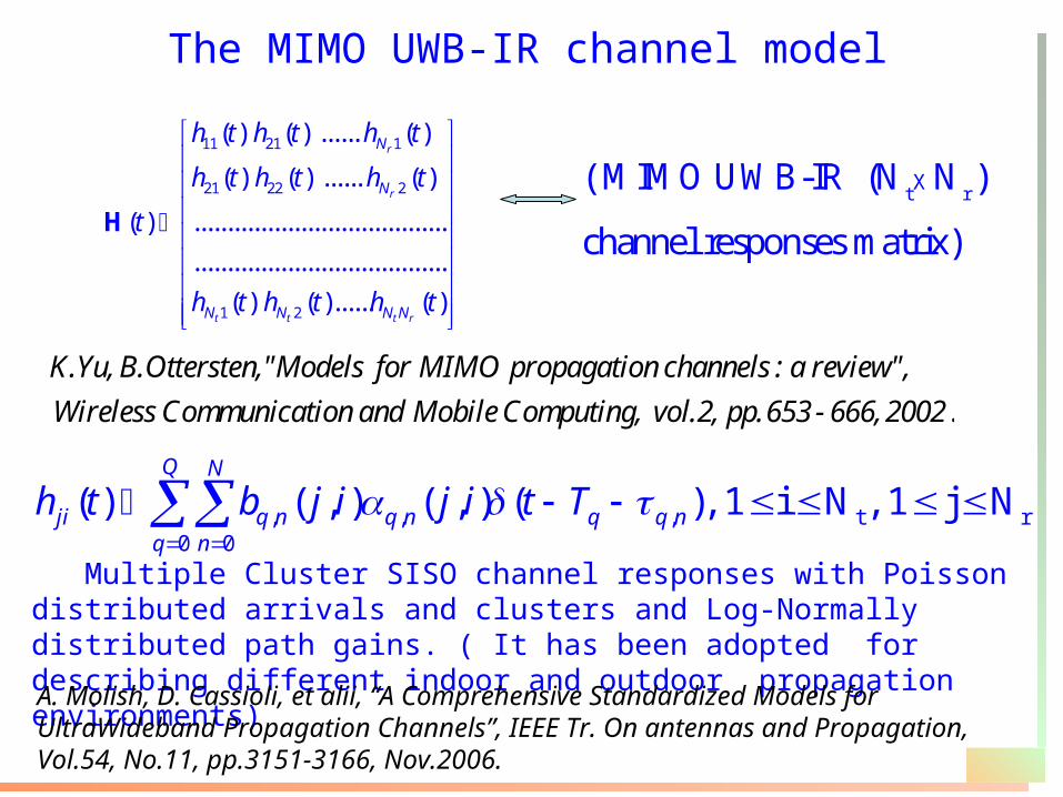
The MIMO UWB-IR channel model
11 21 1
21 22 2
1 2
( ) ( ) ...... ( )
( ) ( ) ...... ( )
( ) ......................................
......................................
( ) ( )...... ( )
r
r
t t t r
N
N
N N N N
h t h t h t
h t h t h t
t
h t h t h t
H t rX ( MIMO UWB-IR (N N )
channel responses matrix)
.
K.Yu, B.Ottersten, "Models for MIMO propagation channels : a review",
Wireless Communication and Mobile Computing, vol.2, pp. 653 - 666, 2002
, , , t r0 0
( ) ( , ) ( , ) ( ), 1 i N , 1 j NQ N
ji q n q n q q nq n
h t b j i j i t T
Multiple Cluster SISO channel responses with Poisson distributed arrivals and clusters and Log-Normally distributed path gains. ( It has been adopted for describing different indoor and outdoor propagation environments)
A. Molish, D. Cassioli, et alii, “A Comprehensive Standardized Models for UltraWideband Propagation Channels”, IEEE Tr. On antennas and Propagation, Vol.54, No.11, pp.3151-3166, Nov.2006.

UWB-IR channel models
SISO
UWB-IR
channel Cluster mean frequency
Ray mean frequency
Cluster decay factor
Ray decay factor
Multipath Spread
CM 1
(LOS) 0.0233 2.5 7.1 4.3 5.05
CM 2
(NLOS) 0.4 0.5 5.5 6.7 10.38
CM 3
(NLOS) 0.0667 2.1 14 7.9 14.18
CM 4
(ENLOS) 0.0667 2.1 24 12 30.1
( sec) T n1 ( sec)n 1( sec) n

Main assumptions on the channel modelA.1) According to J.H.Reed, An introduction to Ultra Wideband Communication
Systems, Prentice Hall 2005 we may approximate each Multiple Cluster SISO channel response
to single cluster one, by considering only the first cluster.A.2) In order to derive the co-decoder block we consider three different
path gains’ ddp: 1) Gaussian 2) Log-Normal 3) Nakagami
A.3) In order to derive the co-decoder block we assume the number V of arrivals and their values to be perfectly estimated
A.4) The path gains are supposed to be spatially uncorrelated A.5) We consider slow-variant fading
0[ ,... ]V

The Co-Decoder block

ML Decoder Block Scheme
Y
rN ( )r t
0{ ,..., }V
Banks of Filters matched to
M-OPPM symbols and their V+1 replicas
1( )y t
( )rNy t
.
DecisionStatistics
Processing and selector of maximum
.
.
NON-COHERENT NON-COHERENT ML ML
SYNCHRONIZERSYNCHRONIZER
1 ( )r t
MLb

Setting of the pulse width TP to mitigate theInter-Pulse-Interference (IPI)
Given the following positions : a) , temporal pulse width (monocycle) used by each transmit antennas b) M, the OPPM constellation cardinality of the symbols used for Space-Time coding of the L-ary
Source Symbols. c) , the exponentially distributed inter-arrivals with arrival mean frequency equal to
Let us set , to meet the following condition:
p
ln(1 )T
M
1i i i
pT (sec.)
pT (sec.)
pT i M for a fraction of the service time, that is
Such choice allows us to mitigate the IPI effect due to the Poisson distributed arrivals
0, no IPI
=0.25, IPI for 25%
of the service time
1(sec )

The outputs of matched filters (matrix representation)
2lgf f
t
N LY H W
N
stands for unitary (MxNt ) Space-Time codeword matrix corresponding to the M-OPPM coded symbols, that is
1[ ( ),...., ( )], 0 1tNl e l e l l L
denotes Unitary (MX1) vector. It is function of the uncoded L-ary source symbol “l”, and biunivocally associated to the M-ary OPPM coded symbol radiated by the i-th transmit antenna
( ) Mie l
H stands for the (Nt X (Nr (V+1)) ) multipath channel matrix
f is the signal to noise ratio per each transmitted bit
W stands for (MxNr (V+1 ) ) Additive Gaussian noise matrix
Nf is the number of frame per each symbol period Ts

Decision Statistics processing and selector of maximum
• The ML Decoder works according to the following criterium:
0 1
ˆ arg max{ }ML ll L
b z
2
0 1 1
0 1 1
0 1 1
( ) ( ) (Gaussian fading )
ln cosh ( ) ( ) ( Log-Normal fading)
ln cosh ( ) ( ) (Nakagami fading)
tr
tr
tr
NNVT
in jn j i
NNVT
il n jn j i
NNVT
in jn j i
y n e l
z y n e l
y n e l
2lge ;nf f c
nt
LN
N
-1
22
1 ;( ) lg
tn
f h f
N
n N L
-1/2
t2h 2
2mN2 2 2 1+
( ) lgnf fn L N

2) Any two distinctive codeword matrices
are composed by 2Nt different columns
Space Time Orthogonal Pulse Position Modulation (STOPPM) codes
Definition 1) The unitary codeword matrices are composed
by M rows and Nt columns. The number M (that is, the OPPM constellation cardinality) is given by product LNt
1 1( ).... ( ) ( ).... ( )t tl mN Ne l e l e m e m e
( / sec/ )B bit Hz 2lg,
( )f p
T
N T
L
L
Es: L=Nt=2
0
10
01
00
00
1
00
00
10
01
M=4
, 0 L -1l l
Property of the STOPPM codes
The spectral efficiency of the STOPPM codes is equal to

The Union-Chenoff upper bound retained STOPPM codes
2
2
20 2
/
2
2
1 ( ) lg
1) 1 ( )1
1 ( ) lg2
r t
fh fV
tE
n fh f
t
N N
Nn L
NP L fading Gaussiano
Nn L
N
2
20 2
4 (2 )2) 1 ( )
( ) 4(lg ( ) )
r tV
tE
n f h
mN
f
N
mNe mP L fading m Nakagami
m LN n
1 1
0 0
13) ,
L L
E lmm l
l m
P PL
2
2 ( , )1
0 1 1
lgexp( ) ( log )
2
ntr
n
cNNV sf f cr j i
lm nn j i t
Le NP E sech C e fading normale
N
( , ) 21 1
2{sec } exp exp 2n ncr j i c
n n rE h C e t C e c t dt
221
lg( , ) ~ ( , ), , f f
n n rt
LNr j i N C
N
“Log-Normal” frustraction integral. It cannot be expressed in closed form .
S.M.Hass, J.H.Shapiro, “Space-Time Codes for Wireless Optical Communications”, Eurasip Journal on Applied Signal Processing, pp. 211-220, no.3, 2002.

Performance of the STOPPM codes
Lg-N fading
Nk- fadingG-fading
Multipath Intense Profile
Nr=3
Nf=6
2 3 4 5 6 7 8 9 1010
-6
10-5
10-4
10-3
10-2
10-1
SNR(dB)
BE
R
Nt=2
Nt=3
Nt=4
CM3’s

1) BER target:
2) Transmit Power: 2.5mW (Typically adopted for outdoor systems)
3) Each parameter of SISO links is according to CM1:
4) The baseband monocycle is equal to the Gaussian pulse second derivative M.Z.Win, R.A.Scholtz, ''Ultra-Wide Banbwidth Time-Hopping Spread Spectrum Impulse Radio for Wireless Multiple Access Communications'', IEEE Tr. on
Comm., vol.48, pp.679-691, Apr.2002.
5) The path loss model is according to the Siviak-Petroff one
K.Siwiak, A.Petroff, ''A Path link model for Ultra Wide Band Pulse Transmissions'', IEEE VTC2001, Rhodes, Greek, May 2001.6) Throughput: 136.0Mbps7) The Log-Normal fading is considered
Coverage Ranges and Troughput (1/2)
610
12.5( sec) , 4.3, 5.05( sec)n T n
p -3dBpT =0.7 nsec, f 2.774GHz, B 2.453GHz

Coverage Ranges and Troughput (2/2)
Nt Nr R(mt)
1 1 12
1 2 26
2 2 32
2 3 47
3 3 55
Table of coverage Ranges reached by the proposed MIMO UWB-IR co-decoder , equipped with the STOPPM codes. Any SISO link is according to CM1.

The IPI effect
2
1 0
IPI
2
1
lg( , ) ( ) ( )
lg( , , ) ( , ) ( , ) ( , , )
tt N Vf f
q n q f pf
Nf
qtf i q n
fn n i n
it
LNy j l h j i d l w j l
N
LNh j f l d T
N
ln(1 )pT
M
CM3’s Multipath Intense ProfileG fading Nt=2, Nr=1, Nf=4
4 6 8 10 12 14 16 1810
-6
10-5
10-4
10-3
10-2
10-1
dB
BE
R
=0=0.65=0.8

Channel Impairments – Spatially correllated Fading (1/2)
1 c 0 0 ............ 0 0
c 1 0 0 ............ 0 0
0 0 1 c ............ 0 0
0 0 c 1 ............ 0 0
...............................
................................
0 0 .....
t rR R
.............. 1 c
0 0 ................... c 1
Spatial Covariance Matrix.
A.Paulray, R.Nabar, D.Gore, Introduction to Space-TimeWireless Communications, Cambridge university Press, 2003.
1/ 2 1/ 2 t w rR H RH

Channel Impariments- Spatially Correlated Fading (2/2)
Lg-N fading
Nt=Nr=2, Nf=12
CM3’s Multipath Intense Profile

Channel Impairments- Cross-Polarization
Nakagami Fading Nt=Nr=2, Nf=15
1 1 .......... 1
1 1 ......... 1
wH=H ⊙X
X
Channel Model
A.Paulray, R.Nabar, D.Gore, Introduction to Space-TimeWireless Communications, Cambridge university Press, 2003.
CM3’s Multipath Intense Profile

Synchronism RecoveryThe ML Synchronizer block

Let us assume that any time arrival estimate is affected by some error , that is
SNR losses due to Asynchronism
[ , ]p pT T ˆ , for any [0,.., ]i i i V

NON-COHERENT NON-COHERENT ML ML
SYNCHRONIZERSYNCHRONIZER
PILOT SIGNALPILOT SIGNAL GENERATOR GENERATOR
FORFOR SYNCHRONISMSYNCHRONISM
RECOVERYRECOVERY
MIMO UWB-IR System Model(with Poisson distributed multipath fading)
1(1)
0
( ) ( )SN
pilot S Wm
x t E s t mT
0, . . .[ ]V
1( )
0
( ) / ( )fN
idata f t f i p
m
UWB IR M OPPM data signal
x t E N p t mT d T
ji0
r t
( ) ( j,i) ( ) ,
1 j N , 1 i N
V
n nn
h t h t
1
rN
j
tN
111( )h t
rN 1( )h t
j1( )h t
t1N ( )h t
r tN N ( )h t
ji0
r t
( ) ( j,i) ( ) ,
1 j N , 1 i N
V
n nn
h t h t
(1)
0
( ,( ) ( ) ( )) j
data signal measured at
j pilo
j t
V
n
han
n
t a
t
en
n
n
h j ir t x t w t
SPACE-TIME CODED SPACE-TIME CODED PACKET TRANSMITTERPACKET TRANSMITTER
ADOPTING OPPMADOPTING OPPMMODULATION FORMAT MODULATION FORMAT
NON-COHERENT NON-COHERENT ML ML
DECODERDECODER
1 0
( ) (( , ) )( )tN
j ji
data signal measured at j thantenna
n
V
n in
h j iy t x w tt

NON Coherent ML Synchronizer- Main Aspects (1/2)
It jointly estimates the number V of arrivals and their values , according to the ML criterium, without any knowledge on the magnitude of the channel coefficients
Such estimation is asymptotically exact
It is pilot-aided
From Cramer-Rao bound point of view, the SIMO version is to prefer to a MIMO version with orthogonal signaling
E.Baccarelli, M.Biagi, C.Pelizzoni, N.Cordeschi, “Multi-Antenna Noncoherent ML Synchronization for UWB-IR faded channels ”, Journal of Communications and Networks (JCN), vol. 8, No.2, pp.194-204, Giugno 2006
0 v,...,

Let us indicate the arrival times’ and channel coefficients vectors, and let be a received signal G.S. representation, then the following joint ML estimation
Joint ML estimation of V and
2
12
21 0 0
1( ); ( ) ( )
Sr NN V
W n jj n mS t
V R s t mT r t dtN
0 0 0... , and (1,1)... ( ,1)....... (1,1)... ( ,1)T T
V r V V rh h h N h h N
ˆ, , ln | , ,arg max0... max
MV MV MVV h p R V h
V N
h
Prop.1Prop.1::
2ˆ, ( );arg max
0...max
MV MVV V R
V N
R
0 v,...,
can be equivalently effected by only estimanting the arrivals times and their number V, that is
with

Properties of the resulting ML equation system :• The i-th equation is function only on the corespondent time
arrival. The (V+1) equations are independent each other• Any solution can be admitted only when :
The ML equations’ system
2
( ); 0i
V R per i V
0 01 1
1 0 0 0 0
ˆ ˆ( ) ( ) ( ) ( ) 0S Sr
T TN NN
W i j W i jj k m
s t kT r t dt s t mT r t dt per i V
ˆi1 01
1
ˆ ˆ ˆ ˆ... 0
ˆ ˆ 0...( 1)
V V
i i PT i V
0,
, 1
0,
ˆ 1,..,
iniz MAX
i iniz i P
R c
T i V
Serial implementation

The expression of Cramer Rao Bound
2
2
1
1ˆ( ) | , per 0,..,
( ,1)r
i i N
S S iS j
E V h i V
N E h j
with
/2
/
0
( ,1)p
p
iT
i VkT
k
eh j
e

+ -
+
Late
LNr
+
(1+Ns)
“early”output
(1)
(2)LOOP
FILTER
Template Signal
Generator
eTw
“late”output
E1
ENr
Early
( ˆ )iv t
+
Tw
( )ˆv t
( )ˆs t
+
L1
Tw
yNr(t)
y1(t)
( ˆ )iv t
MV
X
X
( ˆ )iv t
( )iv tX
yj(t)
dt
dt
blocco Lj
ML Synchronizer
(Early-Late Gate serial version)

Performance of the ML synchronizer
1rN
2rN
4rN

Conclusions The proposed MIMO UWB-IR co-decoder is optimized to work under different path gains pdfs
It works in non-coherent mode
The proposed STOPPM codes can minimize the Union-Chernoff upper bounds
The resulting solution allows to extend the (typically) low coverage of the SISO UWB-IR systems
The proposed ML synchronizer can be simply implemented as serial version of early-late gate.