3 simotion scout simotion lad/fbd 4 5 6 7 8 …€¦ · you will be given an introduction to the...
TRANSCRIPT

SIMOTION
SIMOTION SCOUTSIMOTION LAD/FBD
Programming and Operating Manual
01/2015
Preface
Fundamental safety instructions 1
Description 2
LAD/FBD editor 3
LAD/FBD programming 4
Functions 5
Commissioning (software) 6Debugging Software / Error Handling 7
Application Examples 8
Appendix A
Legal informationWarning notice system
This manual contains notices you have to observe in order to ensure your personal safety, as well as to prevent damage to property. The notices referring to your personal safety are highlighted in the manual by a safety alert symbol, notices referring only to property damage have no safety alert symbol. These notices shown below are graded according to the degree of danger.
DANGERindicates that death or severe personal injury will result if proper precautions are not taken.
WARNINGindicates that death or severe personal injury may result if proper precautions are not taken.
CAUTIONindicates that minor personal injury can result if proper precautions are not taken.
NOTICEindicates that property damage can result if proper precautions are not taken.If more than one degree of danger is present, the warning notice representing the highest degree of danger will be used. A notice warning of injury to persons with a safety alert symbol may also include a warning relating to property damage.
Qualified PersonnelThe product/system described in this documentation may be operated only by personnel qualified for the specific task in accordance with the relevant documentation, in particular its warning notices and safety instructions. Qualified personnel are those who, based on their training and experience, are capable of identifying risks and avoiding potential hazards when working with these products/systems.
Proper use of Siemens productsNote the following:
WARNINGSiemens products may only be used for the applications described in the catalog and in the relevant technical documentation. If products and components from other manufacturers are used, these must be recommended or approved by Siemens. Proper transport, storage, installation, assembly, commissioning, operation and maintenance are required to ensure that the products operate safely and without any problems. The permissible ambient conditions must be complied with. The information in the relevant documentation must be observed.
TrademarksAll names identified by ® are registered trademarks of Siemens AG. The remaining trademarks in this publication may be trademarks whose use by third parties for their own purposes could violate the rights of the owner.
Disclaimer of LiabilityWe have reviewed the contents of this publication to ensure consistency with the hardware and software described. Since variance cannot be precluded entirely, we cannot guarantee full consistency. However, the information in this publication is reviewed regularly and any necessary corrections are included in subsequent editions.
Siemens AGDivision Digital FactoryPostfach 48 4890026 NÜRNBERGGERMANY
Ⓟ 02/2015 Subject to change
Copyright © Siemens AG 2015.All rights reserved

Preface
ScopeThis document is part of the SIMOTION Programming documentation package.
This document applies to SIMOTION SCOUT, the engineering system of the SIMOTION product family, V4.4 in conjunction with:
● A SIMOTION device with the following versions of a SIMOTION Kernel:
– V4.4
– V4.3
– V4.2
– V4.1
– V4.0
– V3.2
● The relevant version of the following SIMOTION Technology Packages, depending on the kernel:
– Cam
– Path (Kernel as of V4.1)
– Cam_ext
– TControl
Information in this manualThe following is a list of chapters included in this manual along with a description of the information presented in each chapter.
● Description (Chapter 1)This chapter shortly defines the LAD and FBD programming languages.
● LAD/FBD Editor (Chapter 2)In this chapter you can learn about the various operator control options in the LAD/FBD Editor.
● Software Programming (Chapter 3)This chapter shows how to proceed during programming.
● Functions (Chapter 4)This chapter describes how to apply individual LAD/FBD commands and gives an outline of their function.
● Debugging Software / Error Handling (Chapter 5)This chapter describes how to test a program and find errors in created programs.
SIMOTION LAD/FBDProgramming and Operating Manual, 01/2015 3

● Application Examples (Chapter 6)You will be given an introduction to the LAD and FBD programming languages using some simple examples.
● Appendix
– Key combinationsThis appendix contains the keystroke combinations for frequently used commands.
● IndexKeyword index for locating information.
SIMOTION DocumentationAn overview of the SIMOTION documentation can be found in the SIMOTION Documentation Overview document.
This documentation is included as electronic documentation in the scope of delivery of SIMOTION SCOUT. It comprises ten documentation packages.
The following documentation packages are available for SIMOTION V4.4:
● SIMOTION Engineering System Handling
● SIMOTION System and Function Descriptions
● SIMOTION Service and Diagnostics
● SIMOTION IT
● SIMOTION Programming
● SIMOTION Programming - References
● SIMOTION C
● SIMOTION P
● SIMOTION D
● SIMOTION Supplementary Documentation
Hotline and Internet addresses
Additional informationClick the following link to find information on the following topics:
● Ordering documentation / overview of documentation
● Additional links to download documents
● Using documentation online (find and search manuals/information)
http://www.siemens.com/motioncontrol/docu
Preface
SIMOTION LAD/FBD4 Programming and Operating Manual, 01/2015

My Documentation ManagerClick the following link for information on how to compile documentation individually on the basis of Siemens content and how to adapt it for the purpose of your own machine documentation:
http://www.siemens.com/mdm
TrainingClick the following link for information on SITRAIN - Siemens training courses for automation products, systems and solutions:
http://www.siemens.com/sitrain
FAQsFrequently Asked Questions can be found in SIMOTION Utilities & Applications, which are included in the scope of delivery of SIMOTION SCOUT, and in the Service&Support pages in Product Support:
http://support.automation.siemens.com
Technical supportCountry-specific telephone numbers for technical support are provided on the Internet under Contact:
http://www.siemens.com/automation/service&support
Preface
SIMOTION LAD/FBDProgramming and Operating Manual, 01/2015 5

Preface
SIMOTION LAD/FBD6 Programming and Operating Manual, 01/2015

Table of contents
Preface.........................................................................................................................................................3
1 Fundamental safety instructions.................................................................................................................17
1.1 General safety instructions.....................................................................................................17
1.2 Industrial security...................................................................................................................18
2 Description..................................................................................................................................................19
2.1 Description.............................................................................................................................19
2.2 What is LAD?.........................................................................................................................20
2.3 What is FBD?.........................................................................................................................21
2.4 Unit, program organization unit (POU) and program source..................................................22
3 LAD/FBD editor..........................................................................................................................................23
3.1 The LAD/FBD editor in the workbench...................................................................................23
3.2 Maximizing working area and detail view...............................................................................25
3.3 Enlarging or reducing the content of the working area...........................................................26
3.4 Bringing the LAD/FBD editor to the foreground.....................................................................27
3.5 Hiding and displaying the declaration table............................................................................28
3.6 Enlarging/reducing the declaration table................................................................................29
3.7 Operation...............................................................................................................................303.7.1 Operating the LAD/FBD editor...............................................................................................303.7.2 Menu bar................................................................................................................................303.7.3 Context menu.........................................................................................................................303.7.4 Toolbars.................................................................................................................................303.7.5 Key combinations...................................................................................................................323.7.6 Drag&Drop of variables..........................................................................................................323.7.7 Drag&drop from the declaration tables..................................................................................323.7.8 Drag&drop within the declaration table..................................................................................323.7.9 Using Drag&Drop for LAD/FBD elements..............................................................................333.7.10 Command call drag&drop......................................................................................................333.7.11 Drag&Drop of command names.............................................................................................333.7.12 Using drag&drop for elements in a network...........................................................................343.7.13 Using drag&drop for functions and function blocks from other sources.................................343.7.14 Automatic completion (Autocomplete)...................................................................................34
3.8 Settings..................................................................................................................................383.8.1 Settings in the LAD/FBD editor..............................................................................................383.8.2 Activating automatic symbol check and type update.............................................................393.8.3 Example of a type update......................................................................................................413.8.4 Example of a symbol check...................................................................................................433.8.5 Deactivating automatic symbol check and type update.........................................................433.8.6 Perform symbol check and type update at a specified time...................................................44
SIMOTION LAD/FBDProgramming and Operating Manual, 01/2015 7

3.8.7 Setting the data type list of the declaration table...................................................................443.8.8 Changing fonts.......................................................................................................................453.8.9 Changing colors.....................................................................................................................453.8.10 Calling online help in the LAD/FBD editor..............................................................................46
4 LAD/FBD programming..............................................................................................................................47
4.1 Programming software...........................................................................................................47
4.2 Managing LAD/FBD source file..............................................................................................484.2.1 Inserting a new LAD/FBD source file.....................................................................................484.2.2 Opening an existing LAD/FBD source file..............................................................................514.2.3 Saving and compiling a LAD/FBD source file........................................................................514.2.4 Closing a LAD/FBD source file...............................................................................................524.2.5 Cut/copy/delete operations in a LAD/FBD source file............................................................524.2.6 Inserting a cut or copied LAD/FBD source file.......................................................................534.2.7 Know-how protection for LAD/FBD source files.....................................................................53
4.3 Exporting and importing LAD/FBD source files......................................................................544.3.1 Exporting a LAD/FBD source file in XML format....................................................................544.3.2 Importing LAD/FBD source files as XML data........................................................................544.3.3 Exporting a POU in XML format.............................................................................................554.3.4 Importing a POU from XML format.........................................................................................554.3.5 Exporting a LAD/FBD source file in EXP format....................................................................554.3.6 Importing EXP data into a LAD/FBD source file.....................................................................56
4.4 LAD/FBD source files - defining properties............................................................................584.4.1 Defining the properties of a LAD/FBD source file..................................................................584.4.2 Renaming a LAD/FBD source file..........................................................................................594.4.3 Making settings for the compiler............................................................................................594.4.3.1 Global compiler settings.........................................................................................................604.4.3.2 Local compiler settings...........................................................................................................60
4.5 Managing LAD/FBD programs...............................................................................................644.5.1 Inserting a new LAD/FBD program........................................................................................644.5.2 Opening an existing LAD/FBD program.................................................................................664.5.3 Defining the order of the LAD/FBD programs in the LAD/FBD source file.............................674.5.4 Copying the LAD/FBD program.............................................................................................674.5.5 Saving and compiling a LAD/FBD program...........................................................................684.5.6 Closing a LAD/FBD program..................................................................................................684.5.7 Deleting the LAD/FBD program.............................................................................................69
4.6 LAD/FBD programs - defining properties...............................................................................704.6.1 Renaming a LAD/FBD program.............................................................................................704.6.2 Changing the LAD/FBD program creation type......................................................................71
4.7 Printing source files and programs.........................................................................................724.7.1 Printing a declaration table.....................................................................................................724.7.2 Printing a network area..........................................................................................................734.7.3 Printing comments.................................................................................................................734.7.4 Defining print variants............................................................................................................734.7.5 Placing networks....................................................................................................................744.7.6 Blank pages...........................................................................................................................74
4.8 LAD/FBD networks and elements..........................................................................................754.8.1 Inserting networks..................................................................................................................764.8.2 Selecting networks.................................................................................................................76
Table of contents
SIMOTION LAD/FBD8 Programming and Operating Manual, 01/2015

4.8.3 Numbering the networks........................................................................................................774.8.4 Enter title/comment................................................................................................................774.8.5 Showing/hiding a jump label..................................................................................................784.8.6 Copying/cutting/pasting networks..........................................................................................794.8.7 Undo/redo actions..................................................................................................................794.8.8 Deleting networks...................................................................................................................80
4.9 Displaying LAD/FBD elements...............................................................................................814.9.1 LAD diagram..........................................................................................................................814.9.2 Meaning of EN/ENO...............................................................................................................824.9.3 FBD diagram..........................................................................................................................834.9.4 Converting between LAD and FBD representation................................................................84
4.10 Editing LAD/FBD elements....................................................................................................864.10.1 Inserting LAD/FBD elements..................................................................................................864.10.2 Syntax check in LAD..............................................................................................................864.10.3 Selecting LAD/FBD elements.................................................................................................874.10.4 Copy/cut/delete operations in LAD/FBD elements.................................................................884.10.5 LAD/FBD elements - defining parameters (labeling)..............................................................884.10.6 Labeling LAD/FBD elements with the symbol input help dialog.............................................884.10.7 Setting the LAD/FBD element display....................................................................................894.10.8 Setting the call parameter for an individual parameter...........................................................894.10.9 Setting call parameters..........................................................................................................90
4.11 Command library....................................................................................................................924.11.1 LAD/FBD functions in the command library...........................................................................924.11.2 Inserting elements/functions from the command library.........................................................934.11.3 Description of PLCopen blocks..............................................................................................934.11.4 Special features of the command library................................................................................95
4.12 General information about variables and data types .............................................................964.12.1 Overview of variable types.....................................................................................................964.12.2 Scope of the declarations.......................................................................................................984.12.3 Rules for identifiers................................................................................................................994.12.4 Frequently used arrays in declarations..................................................................................994.12.4.1 Array length and array element..............................................................................................994.12.4.2 Initial value...........................................................................................................................1004.12.4.3 Comments............................................................................................................................1014.12.5 Sorting in the declaration tables...........................................................................................101
4.13 Data Types ..........................................................................................................................1044.13.1 Elementary data types.........................................................................................................1044.13.1.1 Value range limits of elementary data types........................................................................1064.13.1.2 General data types...............................................................................................................1074.13.1.3 Elementary system data types.............................................................................................1074.13.2 User-defined data types.......................................................................................................1084.13.2.1 Defining user-defined data types (UDT)...............................................................................1084.13.2.2 Scope of the data type declaration.......................................................................................1084.13.2.3 Defining structures...............................................................................................................1084.13.2.4 Defining enumerations.........................................................................................................1094.13.3 Technology object data types..............................................................................................1104.13.3.1 Description of the technology object data types...................................................................1104.13.3.2 Inheritance of the properties for axes...................................................................................1114.13.4 System data types................................................................................................................111
Table of contents
SIMOTION LAD/FBDProgramming and Operating Manual, 01/2015 9

4.14 Variables..............................................................................................................................1134.14.1 Keywords for variable types.................................................................................................1134.14.2 Defining variables.................................................................................................................1144.14.2.1 Use of global device variables.............................................................................................1144.14.2.2 Declaring a unit variable in the source file...........................................................................1154.14.2.3 Declaring local variables......................................................................................................1174.14.2.4 Defining variables in the Variable declaration dialog box ("on-the-fly" variable
declaration)..........................................................................................................................1184.14.2.5 Pasting pragma lines during variable definition....................................................................1214.14.3 Time of the variable initialization .........................................................................................1244.14.3.1 Initialization of retentive global variables..............................................................................1254.14.3.2 Initialization of non-retentive global variables......................................................................1264.14.3.3 Initialization of local variables...............................................................................................1284.14.3.4 Initialization of static program variables...............................................................................1294.14.3.5 Initialization of instances of function blocks (FBs)................................................................1304.14.3.6 Initialization of system variables of technology objects........................................................1314.14.3.7 Version ID of global variables and their initialization during download................................1324.14.4 Variables and HMI devices..................................................................................................134
4.15 Access to inputs and outputs (process image, I/O variables) .............................................1374.15.1 Overview of access to inputs and outputs............................................................................1374.15.2 Important features of direct access and process image access..........................................1384.15.3 Direct access and process image of cyclic tasks.................................................................1414.15.3.1 Address range of the SIMOTION devices............................................................................1434.15.3.2 Rules for I/O addresses for direct access and the process image of the cyclical tasks.......1444.15.3.3 Creating I/O variables for direct access or process image of cyclic tasks...........................1454.15.3.4 Syntax for entering I/O addresses........................................................................................1474.15.3.5 Possible data types of I/O variables.....................................................................................1484.15.3.6 Detailed status of the I/O variables (as of Kernel V4.2).......................................................1484.15.4 Access to fixed process image of the BackgroundTask.......................................................1504.15.4.1 Common process image (as of Kernel V4.2).......................................................................1524.15.4.2 Separate process image (up to Kernel V4.1).......................................................................1544.15.4.3 Absolute access to the fixed process image of the BackgroundTask (absolute PI access)....1564.15.4.4 Syntax for the identifier for an absolute process image access...........................................1574.15.4.5 Defining symbolic access to the fixed process image of the BackgroundTask....................1584.15.4.6 Possible data types for symbolic PI access.........................................................................1594.15.4.7 Example: Defining symbolic access to the fixed process image of the BackgroundTask....1594.15.4.8 Creating an I/O variable for access to the fixed process image of the BackgroundTask.....1604.15.5 Accessing I/O variables........................................................................................................160
4.16 Connections to other program source files or libraries.........................................................1624.16.1 Defining connections............................................................................................................1634.16.1.1 Procedure for defining connections to other program sources (units) ................................1634.16.1.2 Procedure for defining connections to libraries....................................................................1634.16.2 Using the name space.........................................................................................................164
4.17 Subroutine............................................................................................................................1654.17.1 Inserting a function (FC) or function block (FB)...................................................................1674.17.2 Inserting a subroutine call into the LAD/FBD program and assigning parameters..............1674.17.2.1 Overview of parameters for..................................................................................................1684.17.3 Example: Function (FC).......................................................................................................1704.17.3.1 Creating and programming the function (FC) ......................................................................1714.17.3.2 Subroutine call of function (FC)............................................................................................172
Table of contents
SIMOTION LAD/FBD10 Programming and Operating Manual, 01/2015

4.17.3.3 Opening the function (FC) directly from the subroutine call.................................................1754.17.4 Example: Function block (FB)..............................................................................................1754.17.4.1 Creating and programming the function block (FB).............................................................1764.17.4.2 Subroutine call of function block (FB)..................................................................................1774.17.4.3 Creating a function block instance.......................................................................................1774.17.4.4 Programming the subroutine call of the function block........................................................1794.17.4.5 Opening the function block (FB) directly from the subroutine call........................................1824.17.4.6 Accessing the output parameters of the function block retrospectively...............................1834.17.5 Limitations with advance signal switching............................................................................1844.17.6 Interface adjustment with FB/FC..........................................................................................185
4.18 Reference data.....................................................................................................................1904.18.1 Cross reference list..............................................................................................................1904.18.1.1 Generating and updating a cross-reference list...................................................................1904.18.1.2 Content of the cross-reference list.......................................................................................1914.18.1.3 Working with a cross-reference list......................................................................................1934.18.1.4 Filtering the cross-reference list...........................................................................................1934.18.2 Program structure................................................................................................................1944.18.2.1 Content of the program structure.........................................................................................1944.18.3 Code attributes.....................................................................................................................1954.18.3.1 Code attribute contents........................................................................................................1964.18.4 Reference to variables.........................................................................................................196
4.19 Find and replace..................................................................................................................1984.19.1 Find in LAD/FBD unit or LAD/FBD program.........................................................................1984.19.2 Find and replace in LAD/FBD unit or LAD/FBD program.....................................................199
4.20 Execution order....................................................................................................................2024.20.1 Non-optimized execution order............................................................................................2024.20.2 Optimized execution order...................................................................................................203
5 Functions..................................................................................................................................................205
5.1 LAD bit logic instructions......................................................................................................2065.1.1 ---| |--- NO contact................................................................................................................2065.1.2 ---| / |--- NC contact..............................................................................................................2075.1.3 XOR Linking EXCLUSIVE OR.............................................................................................2085.1.4 ---|NOT|--- Invert signal state...............................................................................................2085.1.5 ---( ) Relay coil, output..........................................................................................................2095.1.6 ---( # )--- Connector (LAD)....................................................................................................2095.1.7 ---( R ) Reset output (LAD)...................................................................................................2105.1.8 ---( S ) Set output (LAD).......................................................................................................2115.1.9 RS Prioritize reset flipflop.....................................................................................................2125.1.10 SR Prioritize set flipflop........................................................................................................2135.1.11 --( N )-- Scan edge 1 -> 0 (LAD)...........................................................................................2145.1.12 --( P )-- Scan edge 0 -> 1 (LAD)...........................................................................................2145.1.13 NEG edge detection (falling)................................................................................................2155.1.14 POS edge detection (rising).................................................................................................2165.1.15 Open branch........................................................................................................................2175.1.16 Close branch........................................................................................................................217
5.2 FBD bit logic instructions......................................................................................................2195.2.1 & AND box...........................................................................................................................2195.2.2 >=1 OR box..........................................................................................................................2205.2.3 XOR EXCLUSIVE OR box...................................................................................................221
Table of contents
SIMOTION LAD/FBDProgramming and Operating Manual, 01/2015 11

5.2.4 --| Inserting a binary input....................................................................................................2215.2.5 --o| Negating a binary input..................................................................................................2225.2.6 [=] Assignment.....................................................................................................................2235.2.7 [#] Connector (FBD).............................................................................................................2245.2.8 [R] Reset assignment (FBD)................................................................................................2255.2.9 [S] Set assignment (FBD)....................................................................................................2255.2.10 RS Prioritize reset flipflop.....................................................................................................2265.2.11 SR Prioritize set flipflop........................................................................................................2275.2.12 [N] Scan edge 1 -> 0 (FBD)..................................................................................................2285.2.13 [P] Scan edge 0 -> 1 (FBD)..................................................................................................2295.2.14 NEG edge detection (falling)................................................................................................2305.2.15 POS edge detection (rising).................................................................................................231
5.3 Relational operators.............................................................................................................2325.3.1 Overview of comparison operations.....................................................................................2325.3.2 CMP Compare numbers......................................................................................................232
5.4 Conversion instructions........................................................................................................2355.4.1 TRUNC Generate integer.....................................................................................................2355.4.2 Generating numeric data types and bit data types...............................................................2365.4.3 Generating date and time.....................................................................................................239
5.5 Edge detection.....................................................................................................................2415.5.1 Detection of rising edge R_TRIG.........................................................................................2415.5.2 Detection of falling edge F_TRIG.........................................................................................241
5.6 Counter operations...............................................................................................................2435.6.1 Overview of counter operations...........................................................................................2435.6.2 CTU up counter....................................................................................................................2435.6.3 CTU_DINT up counter..........................................................................................................2445.6.4 CTU_UDINT up counter.......................................................................................................2445.6.5 CTD down counter...............................................................................................................2455.6.6 CTD_DINT down counter.....................................................................................................2465.6.7 CTD_UDINT down counter..................................................................................................2475.6.8 CTUD up/down counter........................................................................................................2475.6.9 CTUD_DINT up/down counter.............................................................................................2495.6.10 CTUD_UDINT up/down counter...........................................................................................250
5.7 Jump instructions.................................................................................................................2515.7.1 Overview of jump operations................................................................................................2515.7.2 ---( JMP ) Jump in block if 1 (conditional).............................................................................2515.7.3 ---( JMPN ) Jump in block if 0 (conditional)..........................................................................2525.7.4 LABEL Jump label................................................................................................................252
5.8 Non-binary logic...................................................................................................................253
5.9 Arithmetic operators.............................................................................................................254
5.10 Numeric standard functions.................................................................................................2565.10.1 General numeric standard functions....................................................................................2565.10.2 Logarithmic standard functions............................................................................................2565.10.3 Trigonometric standard functions.........................................................................................257
5.11 Move....................................................................................................................................2585.11.1 MOVE Transfer value...........................................................................................................258
5.12 Shifting operations...............................................................................................................259
Table of contents
SIMOTION LAD/FBD12 Programming and Operating Manual, 01/2015

5.12.1 Overview of shifting operations............................................................................................2595.12.2 SHL Shift bit to the left.........................................................................................................2595.12.3 SHR Shift bit to the right.......................................................................................................260
5.13 Rotating operations..............................................................................................................2615.13.1 Overview of rotating operations...........................................................................................2615.13.2 ROL Rotate bit to the left......................................................................................................2615.13.3 ROR Rotate bit to the right...................................................................................................262
5.14 Program control instructions................................................................................................2645.14.1 Calling up an empty box.......................................................................................................2645.14.2 RET Jump back....................................................................................................................264
5.15 Timer instructions.................................................................................................................2665.15.1 TP pulse...............................................................................................................................2665.15.2 TON ON delay......................................................................................................................2675.15.3 TOF OFF delay....................................................................................................................268
5.16 Selection functions...............................................................................................................2695.16.1 SEL Binary selection............................................................................................................2695.16.2 MAX Maximum function.......................................................................................................2705.16.3 MIN Minimum function.........................................................................................................2705.16.4 LIMIT Limiting function.........................................................................................................2715.16.5 MUX Multiplex function........................................................................................................272
6 Commissioning (software)........................................................................................................................273
6.1 Commissioning.....................................................................................................................273
6.2 Assigning programs to a task...............................................................................................274
6.3 Execution levels and tasks in SIMOTION............................................................................276
6.4 Task start sequence.............................................................................................................278
6.5 Downloading programs to the target system........................................................................279
7 Debugging Software / Error Handling.......................................................................................................281
7.1 Operating modes for program testing..................................................................................2817.1.1 Modes of the SIMOTION devices........................................................................................2817.1.2 Important information about the life-sign monitoring............................................................2837.1.3 Life-sign monitoring parameters...........................................................................................285
7.2 Editing program sources in online mode..............................................................................286
7.3 Symbol Browser...................................................................................................................2877.3.1 Characteristics.....................................................................................................................2877.3.2 Using the symbol browser....................................................................................................287
7.4 Watch tables........................................................................................................................2907.4.1 Monitoring variables in watch table......................................................................................290
7.5 Variable status.....................................................................................................................292
7.6 Trace....................................................................................................................................294
7.7 Program run.........................................................................................................................2957.7.1 Program run: Display code location and call path................................................................2957.7.2 Program run parameters......................................................................................................2957.7.3 Program run toolbar.............................................................................................................296
Table of contents
SIMOTION LAD/FBDProgramming and Operating Manual, 01/2015 13

7.8 Program status (monitoring program execution)..................................................................2977.8.1 Starting and stopping program status (monitoring program execution)...............................298
7.9 Breakpoints..........................................................................................................................3027.9.1 General procedure for setting breakpoints...........................................................................3027.9.2 Setting the debug mode.......................................................................................................3037.9.3 Define the debug task group................................................................................................3047.9.4 Setting breakpoints..............................................................................................................3067.9.5 Breakpoints toolbar..............................................................................................................3077.9.6 Defining the call path for a single breakpoint.......................................................................3097.9.7 Defining the call path for all breakpoints..............................................................................3117.9.8 Activating breakpoints..........................................................................................................3127.9.9 Display call stack..................................................................................................................3157.9.10 Resuming program execution..............................................................................................3157.9.11 Resuming program execution in single steps (as of Kernel V4.4).......................................316
7.10 Task status function bar.......................................................................................................317
7.11 Project comparison..............................................................................................................318
8 Application Examples...............................................................................................................................319
8.1 Examples.............................................................................................................................319
8.2 Creating sample programs...................................................................................................320
8.3 Blinker program....................................................................................................................3218.3.1 Insert LAD/FBD source file...................................................................................................3228.3.2 Insert LAD/FBD program......................................................................................................3258.3.3 Entering variables in the declaration table...........................................................................3278.3.4 Entering a program title........................................................................................................3288.3.5 Inserting network..................................................................................................................3288.3.6 Inserting an empty box.........................................................................................................3298.3.7 Selecting box type................................................................................................................3308.3.8 Parameterizing the ADD call-up...........................................................................................3328.3.9 Inserting comparator............................................................................................................3338.3.10 Labeling the comparator......................................................................................................3348.3.11 Initializing a coil....................................................................................................................3358.3.12 Inserting next network..........................................................................................................3358.3.13 Details view..........................................................................................................................3368.3.14 Compiling.............................................................................................................................3378.3.15 Assigning a sample program to an execution level..............................................................3388.3.16 Starting sample program......................................................................................................339
8.4 Position axis program...........................................................................................................3418.4.1 Insert LAD/FBD source file...................................................................................................3428.4.2 Insert LAD/FBD program......................................................................................................3428.4.3 Inserting a TO-specific command........................................................................................3448.4.4 Connecting the enable inputs...............................................................................................3478.4.5 Entering variables in the declaration table...........................................................................3518.4.6 Parameterization of the NO contacts...................................................................................3518.4.7 Setting call parameters for the _MC_Power command........................................................3528.4.8 Setting call parameters for the _MC_MoveRelative command............................................3558.4.9 Details view..........................................................................................................................3568.4.10 Compiling.............................................................................................................................3568.4.11 Assigning a sample program to an execution level..............................................................357
Table of contents
SIMOTION LAD/FBD14 Programming and Operating Manual, 01/2015

8.4.12 Starting sample program......................................................................................................357
A Appendix...................................................................................................................................................359
A.1 Key combinations.................................................................................................................359
A.2 Protected and reserved identifiers.......................................................................................362
Index.........................................................................................................................................................363
Table of contents
SIMOTION LAD/FBDProgramming and Operating Manual, 01/2015 15

Table of contents
SIMOTION LAD/FBD16 Programming and Operating Manual, 01/2015

Fundamental safety instructions 11.1 General safety instructions
WARNING
Risk of death if the safety instructions and remaining risks are not carefully observed
If the safety instructions and residual risks are not observed in the associated hardware documentation, accidents involving severe injuries or death can occur.● Observe the safety instructions given in the hardware documentation.● Consider the residual risks for the risk evaluation.
WARNING
Danger to life or malfunctions of the machine as a result of incorrect or changed parameterization
As a result of incorrect or changed parameterization, machines can malfunction, which in turn can lead to injuries or death.● Protect the parameterization (parameter assignments) against unauthorized access.● Respond to possible malfunctions by applying suitable measures (e.g. EMERGENCY
STOP or EMERGENCY OFF).
SIMOTION LAD/FBDProgramming and Operating Manual, 01/2015 17

1.2 Industrial security
NoteIndustrial security
Siemens provides products and solutions with industrial security functions that support the secure operation of plants, solutions, machines, equipment and/or networks. They are important components in a holistic industrial security concept. With this in mind, Siemens’ products and solutions undergo continuous development. Siemens recommends strongly that you regularly check for product updates.
For the secure operation of Siemens products and solutions, it is necessary to take suitable preventive action (e.g. cell protection concept) and integrate each component into a holistic, state-of-the-art industrial security concept. Third-party products that may be in use should also be considered. For more information about industrial security, visit http://www.siemens.com/industrialsecurity.
To stay informed about product updates as they occur, sign up for a product-specific newsletter. For more information, visit http://support.automation.siemens.com
WARNING
Danger as a result of unsafe operating states resulting from software manipulation
Software manipulation (e.g. by viruses, Trojan horses, malware, worms) can cause unsafe operating states to develop in your installation which can lead to death, severe injuries and/or material damage.● Keep the software up to date.
Information and newsletters can be found at: http://support.automation.siemens.com
● Incorporate the automation and drive components into a state-of-the-art, integrated industrial security concept for the installation or machine.For more detailed information, go to: http://www.siemens.com/industrialsecurity
● Make sure that you include all installed products into the integrated industrial security concept.
Fundamental safety instructions1.2 Industrial security
SIMOTION LAD/FBD18 Programming and Operating Manual, 01/2015

Description 22.1 Description
This chapter will give you a brief overview of ladder logic (LAD) and function block diagram (FBD).
SIMOTION LAD/FBDProgramming and Operating Manual, 01/2015 19

2.2 What is LAD?LAD stands for ladder logic. LAD is a graphical programming language. The statement syntax corresponds to a circuit diagram. LAD enables simple tracking of the signal flow between conductor bars via inputs, outputs and operations. LAD statements consist of elements and boxes which are graphically connected to networks (which are displayed in conformity with the IEC 61131-3 standard). LAD operations follow the rules of Boolean logic.
Figure 2-1 Representation of a network in LAD
The LAD program can also be displayed as an FBD program.
The LAD programming languageThe LAD programming language features all the elements required for the creation of a complete user program. LAD features an extensive command set. This includes the various basic operations with a comprehensive range of operands and how to address them. The design of the functions and function blocks enables you to structure the LAD program clearly.
The program packageThe LAD programming package is an integral part of the basic SIMOTION software, so that after your SIMOTION software has been installed, all editor, compiler and test functions for LAD are available for use.
Description2.2 What is LAD?
SIMOTION LAD/FBD20 Programming and Operating Manual, 01/2015

2.3 What is FBD?FBD stands for function block diagram. FBD is a graphics-based programming language that uses the same type of boxes used in boolean algebra to represent logic (networks are displayed in conformity with the IEC 61131-3 standard). In addition, complex functions (e.g. mathematical functions) can be represented directly in conjunction with the logic boxes.
Figure 2-2 Representation of a network in FBD
The FBD program can usually also be displayed as an LAD program.
The FBD programming languageThe FBD programming language features all the elements required for the creation of a complete user program. FBD features an extensive command set. This includes the various basic operations with a comprehensive range of operands and how to address them. The design of the functions and function blocks enables you to structure the FBD program clearly.
The program packageThe FBD programming package is an integral part of the basic SIMOTION software, so that after your SIMOTION software has been installed, all editor, compiler and test functions for FBD are available for use.
Description2.3 What is FBD?
SIMOTION LAD/FBDProgramming and Operating Manual, 01/2015 21

2.4 Unit, program organization unit (POU) and program sourceThe term "unit" represents a program source.
The terms "program organization unit (POU)" and "LAD/FBD program" are generic terms and may refer to a program, a function (FC), or a function block (FB).
The term "program source file" is a generic term and may refer to a LAD/FBD unit, an MCC unit or an ST source file.
Description2.4 Unit, program organization unit (POU) and program source
SIMOTION LAD/FBD22 Programming and Operating Manual, 01/2015
LAD/FBD editor 33.1 The LAD/FBD editor in the workbench
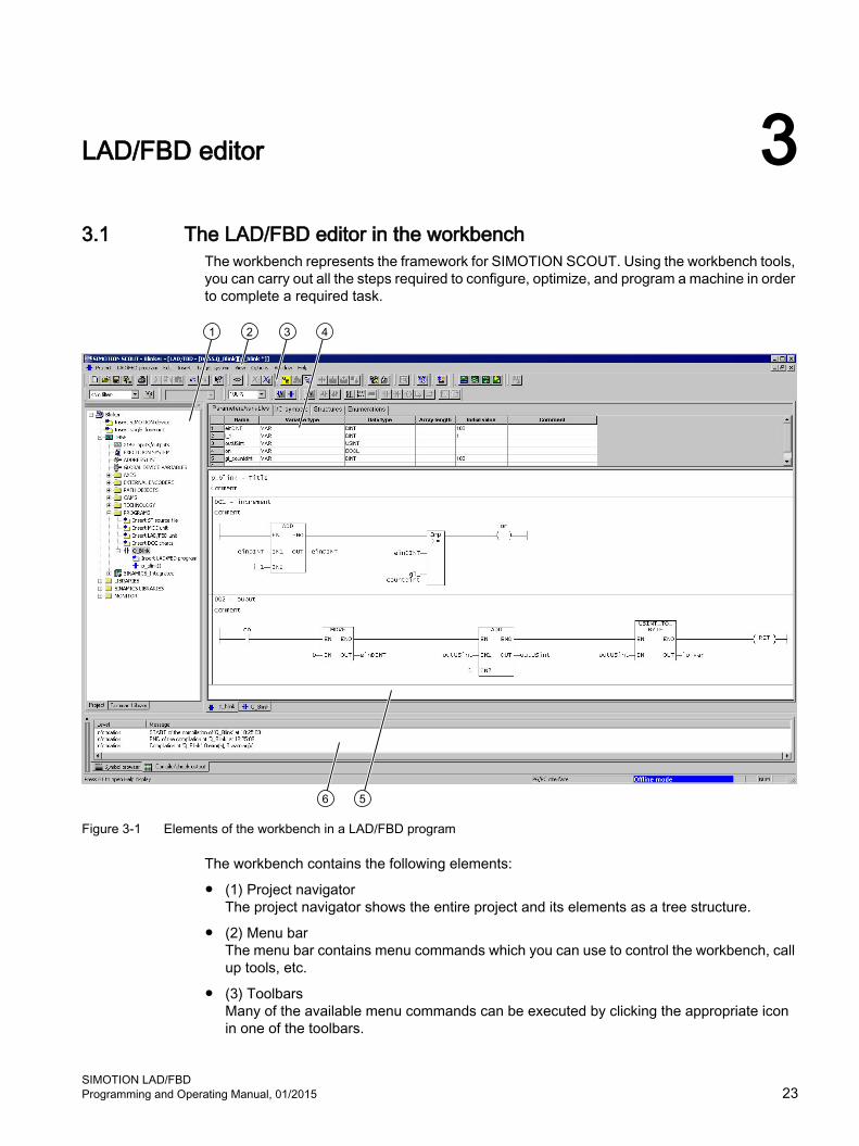
The workbench represents the framework for SIMOTION SCOUT. Using the workbench tools, you can carry out all the steps required to configure, optimize, and program a machine in order to complete a required task.
Figure 3-1 Elements of the workbench in a LAD/FBD program
The workbench contains the following elements:
● (1) Project navigatorThe project navigator shows the entire project and its elements as a tree structure.
● (2) Menu barThe menu bar contains menu commands which you can use to control the workbench, call up tools, etc.
● (3) ToolbarsMany of the available menu commands can be executed by clicking the appropriate icon in one of the toolbars.
SIMOTION LAD/FBDProgramming and Operating Manual, 01/2015 23

● (4) Declaration tablesDeclaration tables are used for LAD/FBD units and programs. You define variables and constants in the declaration tables.
● (5) Working areaIn this area, you carry out job-specific operations. The working area contains an LAD/FBD program, a declaration table, and an editor for graphical displays.
● (6) Detail viewMore detailed information about the elements selected in the project navigator are displayed, e.g. the windows Symbol browsers, Compile/check output.
LAD/FBD editor3.1 The LAD/FBD editor in the workbench
SIMOTION LAD/FBD24 Programming and Operating Manual, 01/2015

3.2 Maximizing working area and detail viewThe windows working area and detail view can be set to maximum zoom.
The selection is made under the following menu items:
● View > Maximize working area (e.g., when creating programs)or
● View > Maximized detail view (e.g., monitoring global variables)
LAD/FBD editor3.2 Maximizing working area and detail view
SIMOTION LAD/FBDProgramming and Operating Manual, 01/2015 25

3.3 Enlarging or reducing the content of the working areaThere are several options available to change the size of the LAD/FBD editor's display, i.e. the size of the elements in this area.
● Zoom list on the Zoom factor toolbar:Select a factor from the Zoom list, or enter an integer value of your own choice.- or - View > Zoom in menu command or View > Zoom out.- or -Key combination Ctrl+Num+ (enlarge) or Ctrl+Num- (reduce).- or -Press the Ctrl key while turning the mouse wheel.
This change always applies to the active LAD/FBD editor. The setting is only saved when saving if changes have been made in the respective editor window.
LAD/FBD editor3.3 Enlarging or reducing the content of the working area
SIMOTION LAD/FBD26 Programming and Operating Manual, 01/2015
3.4 Bringing the LAD/FBD editor to the foregroundIf several LAD/FBD editors are open in the working area, these are usually overlaid. This means that only the top LAD/FBD editor is visible. There are several ways to bring the concealed editors to the foreground.
To bring the editor to the foreground, proceed as follows:
● Select the appropriate tab below the working window- or -Select the appropriate program name in the Window menu.- or -Press the Ctrl+Tab key combination as often as required.
LAD/FBD editor3.4 Bringing the LAD/FBD editor to the foreground
SIMOTION LAD/FBDProgramming and Operating Manual, 01/2015 27

3.5 Hiding and displaying the declaration tableIf you need more space, you can hide the Interface (exported declaration) declaration area and/or the declaration area for a LAD/FBD program completely
To hide and display the declaration table, proceed as follows:
1. Double-click the separation line to hide the declaration table.
2. In order to display the declaration line again, double-click the separation line again.
LAD/FBD editor3.5 Hiding and displaying the declaration table
SIMOTION LAD/FBD28 Programming and Operating Manual, 01/2015

3.6 Enlarging/reducing the declaration tableTo change the size of the declaration table, proceed as follows:
1. Move the mouse cursor onto the separation line until the mouse pointer changes to a double line.
2. Hold down the left mouse button and drag the separation line upwards in order to reduce the size of the declaration area.- or - In order to enlarge the declaration area, move the separation line downwards.
LAD/FBD editor3.6 Enlarging/reducing the declaration table
SIMOTION LAD/FBDProgramming and Operating Manual, 01/2015 29

3.7 Operation
3.7.1 Operating the LAD/FBD editorThe LAD/FBD editor provides the programmer with a variety of different operator input options. Alternatives for executing individual operator inputs include the following:
● The menu bar
● Context menus
● Toolbars
● Key combinations
● Texts and variables can be moved to the input field with drag-and-drop:
– From the project navigator
– From the declaration tables
– From the detail view (Symbol browser tab, address list, watch table)
– From the command library
3.7.2 Menu barYou can start all of the programming functions from the menu bar.
The LAD/FBD program item only appears if a LAD/FBD editor is active in the working area.
3.7.3 Context menuTo use the context menu for an object, proceed as follows:
1. Select the appropriate object with the left mouse button (left click).
2. Briefly click the right mouse button.
3. Left-click the appropriate menu item.
3.7.4 ToolbarsThe dynamic toolbars contain icons for important, frequently used functions, e.g. for inserting or saving elements.
The "dynamic toolbar" changes depending on which workspace is active/selected, e.g. MCC chart, ST program or LAD/FBD program.
The toolbars can be positioned as required within the Workbench. Once moved, they can be shown or hidden using View > Toolbars.
LAD/FBD editor3.7 Operation
SIMOTION LAD/FBD30 Programming and Operating Manual, 01/2015

The LAD/FBD editor toolbar contains the full range of LAD/FBD commands. The command list is displayed whenever the workspace for a program is active or open.
1) Accept and compile2) Insert LAD/FBD program
Figure 3-2 Picture of the toolbar for a LAD/FBD unit
1) Accept and compile 7) Insert NO contact2) Program status 8) Insert NC contact3) Symbol check and type update 9) Insert coil4) Switch to FBD 10) Open branch5) Insert network 11) Close branch6) Jump label ON/OFF 12) Insert comparator 13) Insert an empty box
Figure 3-3 View of the LAD editor toolbar
1) Accept and compile 7) Insert AND box2) Program status 8) Insert OR box3) Symbol check and type update 9) Insert assignment4) Switch to LAD 10) Binary input5) Insert network 11) Negate binary input6) Jump label ON/OFF 12) Insert comparator 13) Insert an empty box
Figure 3-4 View of the FBD editor toolbar
LAD/FBD editor3.7 Operation
SIMOTION LAD/FBDProgramming and Operating Manual, 01/2015 31

3.7.5 Key combinationsUse the key combinations for fast operation in the LAD/FBD editor.
Within an LAD/FBD network, you can switch between LAD/FBD elements, select the required input/output of an LAD/FBD element and switch to the adjacent LAD/FBD network using the left/right arrow buttons and the up/down arrow buttons. Using the Return key, you can open the input field of a selected input/output and make an entry as well as close the field again using the Return key.
The shortcuts (Page 359)available in the LAD/FBD editor are listed in the Appendix.
3.7.6 Drag&Drop of variablesVariables are dragged from the detail view (Symbol browser, Watch table or Address list tab) and dropped in the input field.
To paste in variables using drag&drop, proceed as follows:
1. Left-click the line number of the variable you wish to move. The line with the variables is highlighted.
2. Keeping the left mouse button pressed, drag the line number into the input field of the parameter screen form.
3. Release the left mouse button. The variable is pasted in at the selected position.
3.7.7 Drag&drop from the declaration tablesVariable names can be dragged from a declaration table and dropped into an LAD/FBD network.
To paste in variable names using drag&drop, proceed as follows:
1. Left-click the line number with the name of the variable you wish to move.The line is shown on a black background.
2. Continue to press the left mouse button as you drag the variable name to any input field.
3. Release the left mouse button.The variable name is pasted in at the selected position.
3.7.8 Drag&drop within the declaration tableYou can change the order of the variable declaration in the declaration table.
LAD/FBD editor3.7 Operation
SIMOTION LAD/FBD32 Programming and Operating Manual, 01/2015

To change the order using drag&drop, proceed as follows:
1. Left-click the line number of the variable you wish to move.The line is shown on a black background.
2. Press the Shift key and continue to press the left mouse button as you drag the line to the desired position in the declaration table.A red line indicates the point of insertion.
3. Release the left mouse button.The line moves to the corresponding position.
Note
To move several adjacent lines together, hold the Shift key down as you select the lines you wish to move.
3.7.9 Using Drag&Drop for LAD/FBD elementsLAD/FBD elements can be pasted into the LAD/FBD network from the project navigator (Command library tab) using drag-and-drop.
To paste in LAD/FBD elements using drag&drop, proceed as follows:
1. Left-click the required LAD/FBD element.
2. Hold the left mouse button down and drag the LAD/FBD element into the ladder diagram line of the LAD/FBD network.
3. Release the left mouse button.The LAD/FBD element is pasted in at the selected position.
3.7.10 Command call drag&dropThe commands in the command library can be inserted into LAD/FBD programs.
To insert command calls using drag&drop, proceed as follows:
1. Left-click the required command call.
2. Continue to hold the left mouse button down as you drag the command call to the LAD/FBD program.
3. Release the left mouse button.The command call is inserted at the selected position.
3.7.11 Drag&Drop of command namesCommand names can be moved using drag-and-drop from the project navigator (tab Command library) into the input field of an empty box that has already been generated.
LAD/FBD editor3.7 Operation
SIMOTION LAD/FBDProgramming and Operating Manual, 01/2015 33

To paste in command names using drag&drop, proceed as follows:
1. Left-click the required command name.
2. Holding the left mouse button down, drag the command name into the input field of an empty box.
3. Release the left mouse button.The command name is pasted in at the selected position.
3.7.12 Using drag&drop for elements in a networkTo insert elements in a network using drag&drop, proceed as follows:
1. Left-click the required LAD element.
2. To move an element, proceed as follows:Holding the left mouse button down, drag the element to the required position in the ladder diagram line.
3. To copy an element, proceed as follows:Keeping the CTRL key depressed, drag the element with the left mouse button to the required position in the ladder diagram line.
4. Release the left mouse button. The LAD element is inserted at the selected position.
3.7.13 Using drag&drop for functions and function blocks from other sourcesSuccessfully compiled functions and function blocks from other source files can be pasted into a ladder diagram line from the project navigator. The connection to the "original source" is automatically entered in the Connections tab of the current source file.
To paste in functions and function blocks using drag&drop, proceed as follows:
1. Left-click the required FC/FB.
2. Holding the left mouse button down, drag the FC/FB into the input field of an empty box.
3. Release the left mouse button.An FC/FB call box is pasted in.
3.7.14 Automatic completion (Autocomplete)In the LAD/FBD editor, you can automatically complete identifiers. A drop-down list box with identifiers that begin with the previously entered characters will be displayed. This operates on a context-sensitive basis, whereby the expected type for the identifier being sought and its visibility in the current program context determine which entries are displayed as options in the drop-down list box.
LAD/FBD editor3.7 Operation
SIMOTION LAD/FBD34 Programming and Operating Manual, 01/2015

Depending on the context, the entries displayed in the drop-down list box are filtered and sorted:
● The filtering process may determine, for example, that only structure components are displayed for a structure.
● Entries are sorted according to their relevance to the context, with the more relevant identifiers appearing higher in the list (e.g. local variables are listed before global variables).
With LAD/FBD source files and LAD/FBD programs, the identifiers can be completed automatically in the following input fields/editable drop-down list boxes:
● Declaration table of the LAD/FBD unit
– "Type" column
– "Variable type" column
– "Data type" column
● Declaration table of the LAD/FBD program
– "Variable type" column
– "Data type" column
● Input fields for the inputs of an LAD/FBD element (variables and other symbols for the expected type)
● Input fields for the outputs of an LAD/FBD element (variables for the expected type)
● Input field for the instance variable of a function block (variables for the expected FB type (box type))
● Input field for the NC contact, NO contact, and coil LAD elements (BOOL type variables)
LAD/FBD editor3.7 Operation
SIMOTION LAD/FBDProgramming and Operating Manual, 01/2015 35

Figure 3-5 Automatic completion of an identifier at the input for an LAD/FBD element
ProcedureTo complete an identifier automatically (Autocomplete), proceed as follows:
1. Write the first characters of the identifier (e.g. the first letters of a word) in the input field/editable drop-down list box.
2. Press the Ctrl+space key combination.A drop-down list box opens containing the filtered/sorted identifiers for the current context. The identifiers listed start with the characters input so far or the characters up to where the cursor is positioned within an existing identifier.
Note
When the drop-down list box has been expanded and is editable (by clicking the symbol), automatic completion is already activated.
3. Expand or refine the options displayed:
– Enter additional characters.
– Delete characters.
– Move the cursor with the left/right arrow keys.
LAD/FBD editor3.7 Operation
SIMOTION LAD/FBD36 Programming and Operating Manual, 01/2015

4. Select the required identifier with the up/down arrow keys.
5. Press the Return key.The identifier is accepted by the input field/editable drop-down list box and the current word is overwritten.
Note
If only a single identifier is offered for selection, the selection window will not be opened and the identifier completed immediately.
Functional descriptionThe following identifiers that begin with the specified characters will be offered:
● ST expressions
● ST program sections
● Identifiers from the command library
● Library, unit, POU, or system function names
● For technology objects including their system variables and configuration data
● Identifiers for the relevant LAD/FBD unit or LAD/FBD program:
– Program organization units (POU) and FB instances
– Data types
– Variables and constants
– Structure elements
● Identifiers from imported program sources
Note
Identifiers from the relevant LAD/FBD unit or LAD/FBD program or from imported program sources will only be displayed correctly if the corresponding program source has been compiled.
The display operates on a context-sensitive basis, i.e. only those types of identifiers that are appropriate at the associated location of the LAD/FBD unit or LAD/FBD program are offered:● Within a declaration table, data types and variable types only● Within a program organization unit (POU), no data types● For a structure (e.g. var_struct.xx), only structure components
LAD/FBD editor3.7 Operation
SIMOTION LAD/FBDProgramming and Operating Manual, 01/2015 37

3.8 Settings
3.8.1 Settings in the LAD/FBD editorYou can define the layout for creating a program in the LAD/FBD programming language:
1. To change the settings, select the Options > Settings menu command.The Settings dialog box opens.
2. Select the tab LAD/FBD editor.
3. Make the required settings here.
4. Click OK or Accept to confirm.
Figure 3-6 LAD/FBD editor settings
The table below contains a description of the individual parameters.
Table 3-1 LAD/FBD editor parameter settings
Parameter DescriptionDefault language Defines the default graphical programming language for cre‐
ating a new LAD/FBD program in the LAD/FBD editor."On-the-fly" variable declaration If activated, a dialog box appears when an unknown symbol
is entered in the LAD or FBD diagram. You can carry out the variable declaration in this dialog box.See: Defining variables in the Variable declaration dialog box ("on-the-fly" variable declaration) (Page 118)
LAD/FBD editor3.8 Settings
SIMOTION LAD/FBD38 Programming and Operating Manual, 01/2015

Parameter DescriptionOnly known types if type lists exist If activated, only those function blocks which also have an
entry in the Connections tab appear in the list of data types.See: Setting the data type list of the declaration table
Automatic symbol check and type up‐date
If active, an automatic symbol check and type update take place once changes affecting the LAD/FBD program open in the LAD/FBD editor have been made in the project.The automatic symbol check and type update are activated by default in the LAD/FBD editor.See: Activating automatic symbol check and type update Example of a type update (Page 41) Example of a symbol check (Page 43) Deactivating automatic symbol check and type update Performing symbol check and type update at a specified time
Operand You can change the options for displaying the operand by entering the number of Characters per line and Number of lines for the Operand field.
Comment You can change the options for displaying the comment by entering the number of Characters per line and Number of lines for the Comment field.
Fonts and colors You can change the fonts and colors of the LAD/FBD editor.See: Changing fonts Changing colors
Format for status display Format in which the values of variables with bit data type are displayed in program status and variable status.See:Starting and stopping the program execution monitoring (Page 298) Variable status (Page 292)
3.8.2 Activating automatic symbol check and type updateTo enable automatic symbol check and type update, follow these steps:
1. Select the Options > Settings menu item.
2. Select the tab LAD/FBD editor.
3. Activate the checkbox Automatic symbol check and type update.
4. Confirm with OK.
Note
The automatic symbol check and type update is activated by default in the LAD/FBD editor.
LAD/FBD editor3.8 Settings
SIMOTION LAD/FBDProgramming and Operating Manual, 01/2015 39

If the symbol check is activated, the automatic symbol check and type update is performed for an LAD/FBD program if the following requirements are met:
● changes are made in the project (see list below) which impact upon the LAD/FBD program
● the focus is on the LAD/FBD program, i.e. it is opened in the KOP/FUP editor, or the LAD/FBD editor from the LAD/FBD program which is already open appears in the foreground (Page 27)
In the event of subsequent changes within a project, automatic symbol check and type update is performed for an LAD/FBD program if the change affects the LAD/FBD program:
● A program source is changed, e.g. deleted or renamed.The changes are only identified for associated program sources and their LAD/FBD programs when the changed program source is compiled. In other words, to enable the automatic symbol check and type update to take place, the changed program source must be compiled before the focus changes to an LAD/FBD program from an associated program source.
● The declaration tables in the LAD/FBD source file and/or from LAD/FBD programs within the LAD/FBD source file are changed.The symbol check/type update takes place for an LAD/FBD program belonging to the LAD/FBD source file if the changes affect that LAD/FBD program.The following cases are possible:
– A declaration table is changed within an LAD/FBD program.The automatic symbol check and type update only takes place after changing from the declaration table to the network.
– The change within a declaration table takes place within an LAD/FBD program and affects another LAD/FBD program within the same program source.The automatic symbol check and type update takes place when the focus is on that other LAD/FBD program.
– Changes within a declaration table take place within a program source and affect an LAD/FBD program in another program source.The automatic symbol check and type update for the LAD/FBD program from another program source can only take place once the changed program source has been compiled.
● A technology object (such as an axis) used by the LAD/FBD program is changed.The automatic symbol check and type update takes place when the focus is on the LAD/FBD program.
Note
The term "LAD/FBD program" is a generic term and may refer to a program, a function (FC), or a function block (FB).
LAD/FBD editor3.8 Settings
SIMOTION LAD/FBD40 Programming and Operating Manual, 01/2015

If you click the mouse on the relevant place in the network (box parameter, input field, symbol highlighted in red) following a symbol check/type update, the tool tip indicates the following:
● the expected data type among the box parameters
● The data type of the variable with labeled input fields
● the cause of trouble in symbols which are highlighted in red whereby the symbol errors may have the following reasons:
– The specified symbol does not exist
– The specified symbol is not visible in the current context (incorrect or missing entry of the connections in the declaration table)
– The specified variable does not have the appropriate type
Note
The symbol check is automatically updated as soon as the declaration table has been edited and left. All errors, including errors in the declaration table, are displayed in the detail view.
3.8.3 Example of a type update
IntroductionDuring the type update all the data types used are updated:
● the list of permitted data types in an input field
● an LAD/FBD program's box type, i.e. in terms of the creation type (program, FB or FC) selected for the LAD/FBD program
● a box's interface in terms of the list of permitted data types per box parameter
● other data types (structures, enumerations, etc.)
For example, a structure AAA {a : BOOL} is used in an LAD/FBD program. If this structure is changed, e.g. AAA {a : BOOL, b : LREAL}, this change is applied by the LAD/FBD program during the type update.
Initial situationThe following are present:
● an ST source ST_1 with a function block FB_1
● an ST source ST_2 with a function block FB_2
● an LAD/FBD unit LADFBD_1 with an LAD/FBD program PROGRAM_1
● FB_1 is called within ST_2, i.e. a connection (Page 162) to ST_1 has to be declared in the ST_2 declaration table
LAD/FBD editor3.8 Settings
SIMOTION LAD/FBDProgramming and Operating Manual, 01/2015 41

● FB_1 is called within PROGRAM_1, i.e. a connection (Page 162) to ST_1 has to be declared in the LADFBD_1 declaration table
● FB_2 is called within PROGRAM_1, i.e. a connection (Page 162) to ST_2 has to be declared in the LADFBD_1 declaration table
How the type update worksThis is a special scenario where a program source (in this case LADFBD_1) imports another program source (in this case ST_1) both explicitly and by means of inheritance. Inheritance takes place via another imported program source (in this case ST_2) which, in turn, imports other sources (in this case ST_1).
① LADFBD_1 explicitly imports ST_1② LADFBD_1 imports ST_1 by means of inheritance (ST_1 → ST_2 → LADFBD_1)
Figure 3-7 Special scenario of explicit import and inheritance
Changes are now made at the interface of the FB_1, for example one or more input/output parameters are added (see also interface adjustment in FB/FC (Page 185)) and ST_1 is recompiled.
When PROGRAM_1 is opened in the LAD/FBD editor, the FB_1 call is automatically updated, i.e. a type update occurs via which the changed interface is updated.
Despite the fact that the type update runs error-free, the compiler issues an error message during the compilation of LADFBD_1 because the import of ST_1 by inheritance via the imported ST_2 presupposes that ST_2 is also recompiled.
LAD/FBD editor3.8 Settings
SIMOTION LAD/FBD42 Programming and Operating Manual, 01/2015

In order to recompile ST_2 without errors, the changed interface of the FB_1 call must be updated manually within ST_2.
Note
If program sources are imported which import other program sources themselves (inheritance), an error message may be output by the compiler during the compilation of the program source which is being imported, even if the type update runs error-free.
3.8.4 Example of a symbol check
IntroductionDuring the symbol check, the symbols used in the network are checked in context.
For example, the network includes a box with a BOOL-type input. An LREAL-type variable is now assigned to this input. The symbol check determines that this variable cannot be used in this context and, therefore, flags up this variable in red.
Initial situationThe following are present:
● an ST source ST_1 with the unit variable VAR_1
● an LAD/FBD unit LADFBD_1 with an LAD/FBD program PROGRAM_1
● the unit variable VAR_1 is used within PROGRAM_1, i.e. a connection (Page 163) to ST_1 has to be declared in the LADFBD_1 declaration table
How the symbol check worksThe unit variable VAR_1 is now changed, e.g. the name is changed.
If ST_1 is recompiled after this change, the unit variable VAR_1 is invalid in LADFBD_1.
When PROGRAM_1 is opened in the LAD/FBD editor, an automatic symbol check is performed, i.e. the changed variable is highlighted in red lettering.
The changed variable must be updated manually in PROGRAM_1.
3.8.5 Deactivating automatic symbol check and type updateThe automatic update of the symbol check and type database should only be deactivated if computation speed is unduly reduced, e.g. if a large project is being processed on a slow computer and the hourglass is displayed after any change in the declaration table or in referenced external units.
LAD/FBD editor3.8 Settings
SIMOTION LAD/FBDProgramming and Operating Manual, 01/2015 43

To deactivate automatic symbol check and type update, proceed as follows:
1. Select the Options > Settings menu item.
2. Select the LAD/FBD editor tab.
3. Deactivate the Automatic symbol check and type update checkbox.
4. Confirm with OK.
Note
If the automatic symbol check is deactivated, the display may sometimes be inaccurate, e.g. after an external call has been inserted, the call box interface may be incorrectly displayed (i.e. not updated), or not displayed at all. This is because the current information only becomes available to the LAD/FBD editor after the "Symbol check and type update at a specified time" (Page 44) has been called.
3.8.6 Perform symbol check and type update at a specified timeTo perform a symbol check at a specified time, proceed as follows:
● Select the LAD/FBD program > Symbol check and type update menu item (shortcut Ctrl+T).- or -Click the Symbol check and type update icon.
Note
The symbol check at a specified time can only be performed when the "Automatic symbol check and type update" (Page 39) is deactivated.
3.8.7 Setting the data type list of the declaration tableIn the declaration area, all function blocks of the project not used in the program are stated in the list of data types by default.
To improve clarity, it is possible to set that only those function blocks are displayed for which an entry in the Connections tab exists.
To set the data type display, proceed as follows:
1. Select the Options > Settings menu item.
2. Select the tab LAD/FBD editor.
3. Click the Only known types if type lists exist check box.
4. Confirm with OK.
LAD/FBD editor3.8 Settings
SIMOTION LAD/FBD44 Programming and Operating Manual, 01/2015

3.8.8 Changing fontsUse the following procedure to change the font of the LAD/FBD editor:
1. Select the Options > Settings menu command.
2. Select the LAD/FBD editor tab.
3. Click the Fonts and colors button.The Fonts and colors dialog box with the Fonts tab appears.
4. Select the font, font size, type, or display you require.
Figure 3-8 Fonts and colors dialog box
5. Confirm with OK.
3.8.9 Changing colorsUse the following procedure to change the colors of the LAD/FBD editor:
1. Select the Options > Settings menu command.
2. Select the LAD/FBD editor tab.
3. Click the Fonts and colors button.The Fonts and colors dialog box appears.
4. Click the Colors tab.
LAD/FBD editor3.8 Settings
SIMOTION LAD/FBDProgramming and Operating Manual, 01/2015 45

5. Select the required color.
Figure 3-9 Fonts and colors dialog box
6. Confirm with OK.
3.8.10 Calling online help in the LAD/FBD editorThe online help can provide assistance for many of the operating steps. Call up the online help using either the:
● Help menu
– Help topics
– Context-sensitive help
– Getting Started
● General help with the F1 key
● Help button, which appears in an open dialog box
● Context-sensitive help with the Shift+F1 key combination or the arrow with question mark icon (also for LAD/FBD elements in a network).
LAD/FBD editor3.8 Settings
SIMOTION LAD/FBD46 Programming and Operating Manual, 01/2015

LAD/FBD programming 44.1 Programming software
This chapter describes the various operator control options in the LAD/FBD editor and the basic procedure for LAD/FBD programming.
SIMOTION LAD/FBDProgramming and Operating Manual, 01/2015 47

4.2 Managing LAD/FBD source fileLAD/FBD units are assigned to the SIMOTION device on which the LAD/FBD programs contained in the unit will subsequently be run (e.g. SIMOTION D455-2). They are stored in the project navigator under the SIMOTION device in the PROGRAMS folder.
The individual program organization units (POU, LAD/FBD programs) are stored under a LAD/FBD unit.
Note
ST source files, MCC units and DCC charts are also stored in the PROGRAMS folder under the SIMOTION device.
For a description of the SIMOTION ST (Structured Text) programming language, refer to the SIMOTION ST Programming and Operating Manual.
For a description of the SIMOTION MCC (Motion Control Chart) programming language, refer to the SIMOTION MCC Programming and Operating Manual.
4.2.1 Inserting a new LAD/FBD source fileLAD/FBD units are assigned to the SIMOTION device on which the LAD/FBD programs contained in the unit will subsequently be run (e.g. SIMOTION D455-2).
There are several ways of inserting a new LAD/FBD unit.
● In the project navigator: in the PROGRAMS folder using the Insert LAD/FBD unit element
● Select the PROGRAMS folder in the project navigator and choose the command Insert > Program > LAD/FBD unit in the menu.
● Select the PROGRAMS folder in the project navigator and choose the command Insert new object > LAD/FBD unit in the context menu.
ProcedureTo insert a new LAD/FBD unit using the context menu:
1. Open the appropriate SIMOTION device in the project navigator.
2. Select the PROGRAMS folder.
3. Select the Insert new object > Insert LAD/FBD unit context menu.
LAD/FBD programming4.2 Managing LAD/FBD source file
SIMOTION LAD/FBD48 Programming and Operating Manual, 01/2015

4. Enter the name of the LAD/FBD unit.The names of program sources must comply with the rules for identifiers (Page 99): They are made up of letters (A … Z, a … z), numbers (0 … 9), or single underscores (_) in any order, whereby the first character must be a letter or underscore. No distinction is made between upper- and lower-case letters.The permissible length of the name depends on the SIMOTION Kernel version:
– SIMOTION Kernel as of version V4.1: a maximum of 128 characters.
– SIMOTION Kernel up to version V4.0: a maximum of 8 characters.
Names must be unique within the SIMOTION device. Protected or reserved identifiers (Page 362) are not permitted.Existing program sources (e.g. LAD/FBD units, ST source files) are displayed.
5. You can also enter an author, version, and a comment.
6. Activate the Open editor automatically checkbox.
7. If necessary, select the Compiler tab and make any local compiler settings; see Local compiler settings (Page 60).
8. Confirm with OK.
Note
When you click OK, the LAD/FBD unit is transferred to the project only. The data, together with the project, is only saved to the data carrier if you select, for example, Project > Save, Project > Save and compile changes, or Project > Save and recompile all.
LAD/FBD programming4.2 Managing LAD/FBD source file
SIMOTION LAD/FBDProgramming and Operating Manual, 01/2015 49

Figure 4-1 Insert LAD/FBD Unit dialog box
Figure 4-2 New LAD/FBD unit (declaration table for the interface and implementation sections)
LAD/FBD programming4.2 Managing LAD/FBD source file
SIMOTION LAD/FBD50 Programming and Operating Manual, 01/2015

4.2.2 Opening an existing LAD/FBD source file
ProcedureTo open an existing LAD/FBD unit, proceed as follows:
1. Open the subtree of the appropriate SIMOTION device in the project navigator.
2. Open the PROGRAMS folder.
3. Select the required LAD/FBD unit.
4. Select the Open context menu.
5. Only for LAD/FBD units with know-how protection (Page 53):If the LAD/FBD unit (or a program of this unit) is not already open and the login assigned to the LAD/FBD unit is not yet logged in:
– Enter the corresponding password for the displayed login.The know-how protection for this unit is temporarily canceled (until the unit and all its programs are closed).
– If required, activate the "Use login as a standard login" checkbox.You will be logged in with this login and can now open additional units to which the same login is assigned without having to re-enter the password.
The LAD/FBD unit (declaration table) opens in the workspace. Multiple units can be opened.
Note
You can also double-click the required LAD/FBD unit to open it.
4.2.3 Saving and compiling a LAD/FBD source file
Requirements:Ensure that the LAD/FBD unit or one of the associated LAD/FBD programs is the active window in the workbench.
To save a LAD/FBD unit and all its associated LAD/FBD programs in the project and start the compiler:
● Select the Save and compile icon in the LAD/FBD editor toolbar.- or -Select the LAD/FBD unit > Save and compile menu item.- or -Select the LAD/FBD unit or a LAD/FBD program in the project navigator and select Save and compile in the context menu.- or -Shortcut Ctrl+B.
LAD/FBD programming4.2 Managing LAD/FBD source file
SIMOTION LAD/FBDProgramming and Operating Manual, 01/2015 51

Note
Save and compile only applies the changes to LAD/FBD units and associated LAD/FBD programs in the project. The data is only saved to the data carrier, together with the project, if you select Project > Save or Project > Save and compile changes.
A LAD/FBD unit can also be saved outside the project (exported).
Error messages and warnings relating to compilation are displayed in the Compile/check output tab in the detail view.
4.2.4 Closing a LAD/FBD source fileTo close a LAD/FBD unit opened in the working window, proceed as follows:
1. Click the x button (cross) in the title bar of the dialog box of the LAD/FBD unit.- or -Select the LAD/FBD unit > Close menu item.- or -Select Windows > Close all windows menu item.- or -Shortcut Ctrl+F4.If the changes have not yet been saved in the project, you can save or cancel them, or abort the close operation.
4.2.5 Cut/copy/delete operations in a LAD/FBD source fileA LAD/FBD source file can be cut or copied together with all its associated LAD/FBD programs and pasted into the same or another SIMOTION device.
It is not possible to paste in a LAD/FBD source file that has been deleted.
To cut, copy or delete, proceed as follows:
1. In the project navigator, select the required LAD/FBD source file.
2. In the context menu, select the appropriate item (Cut, Copy, or Delete).
3. Change the name, if necessary (refer to "See also").
See alsoRenaming a LAD/FBD source file (Page 59)
LAD/FBD programming4.2 Managing LAD/FBD source file
SIMOTION LAD/FBD52 Programming and Operating Manual, 01/2015
4.2.6 Inserting a cut or copied LAD/FBD source fileTo paste in a cut or copied LAD/FBD source file:
1. Under the SIMOTION device, select the PROGRAMS folder.
2. In the context menu, select Paste.The LAD/FBD source file is pasted in under a new name.
3. If required, amend the name.
4.2.7 Know-how protection for LAD/FBD source filesYou can protect LAD/FBD units against being accessed by unauthorized third parties. Protected LAD/FBD units and all associated LAD/FBD programs can only be opened or exported in EXP format when the password is entered.
The SIMOTION online help provides additional information on know-how protection.
Note
If you export in XML format, the LAD/FBD units are exported in an encrypted format. When importing the encrypted XML files, the know-how protection, including login and password, is retained.
LAD/FBD programming4.2 Managing LAD/FBD source file
SIMOTION LAD/FBDProgramming and Operating Manual, 01/2015 53

4.3 Exporting and importing LAD/FBD source filesThe export and import functions offer you the option of saving a LAD/FBD source file outside the project on your hard disk so that you can copy it from there into another project.
4.3.1 Exporting a LAD/FBD source file in XML formatYou can use an XML export to save an LAD/FBD unit in a directory outside the project, independently of any particular version or platform.
To export a LAD/FBD unit in XML format:
1. In the project navigator, select the required LAD/FBD unit.
2. Select the Expert > Save project and export object context menu or the Project > Save and export menu.
3. Select the directory for the XML export and confirm with OK.
Note
Structures (e.g. several POUs in one unit, advance binary switching) can be used with SIMOTION Kernel as of version V4.1. These structures may not be supported by previous versions.
Note
LAD/FBD units with know-how protection can also be exported in XML format. The LAD/FBD units are exported in encrypted format. When importing the encrypted XML files, the know-how protection, including login and password, is retained.
4.3.2 Importing LAD/FBD source files as XML dataTo import a LAD/FBD source file in XML format:
1. In the project navigator, select the PROGRAMS entry or a LAD/FBD source file.
2. In the context menu, select Import object or Expert > Import object.
3. Select the XML data to be imported and click OK to confirm.The LAD/FBD source file is inserted.
LAD/FBD programming4.3 Exporting and importing LAD/FBD source files
SIMOTION LAD/FBD54 Programming and Operating Manual, 01/2015

4.3.3 Exporting a POU in XML format
Note
Structures (e.g. several POUs in one unit, advance binary switching) can be used with SIMOTION Kernel as of version V4.1. These structures may not be supported by previous versions.
You can use an XML export to save individual program organization units in a directory outside the project, independently of any particular version or platform.
To export a POU in XML format, proceed as follows:
1. In the project navigator in the LAD/FBD unit, select the POU you want to export.
2. In the context menu, select Export as XML.
3. Only for POUs in LAD/FBD units with know-how protection and which are not already open:If the associated LAD/FBD unit (or a POU of this unit) is not already open and the login assigned to the LAD/FBD unit is not yet logged in:
– Enter the corresponding password for the displayed login.The know-how protection for this chart is temporarily canceled (for this export).
– If required, activate the Use login as a standard login checkbox.You will be logged in with this login and can now export or open additional units to which the same login is assigned without having to re-enter the password.
4. Select the directory for the XML export and confirm with OK.
5. Enter the path and file name for the XML export and click Save to confirm.
The POU is saved as XML format; the file name is given the default extension *.xml
Note
A POU with know-how protection is exported without protection.
4.3.4 Importing a POU from XML formatTo import a POU in XML format, proceed as follows:
1. In the project navigator, select the PROGRAMS entry or a LAD/FBD unit.
2. In the context menu, select Import object.
3. Select the XML data to be imported and click OK to confirm.The POU is inserted.
4.3.5 Exporting a LAD/FBD source file in EXP formatWith the export in the EXP format, you can save an LAD/FBD unit in a format that can also be interpreted by third-party controllers.
LAD/FBD programming4.3 Exporting and importing LAD/FBD source files
SIMOTION LAD/FBDProgramming and Operating Manual, 01/2015 55

To export an LAD/FBD unit in EXP format, proceed as follows:
1. Select the LAD/FBD unit in the project navigator.
2. Select the context menu Expert > Export as .EXP.
3. Only for LAD/FBD units with know-how protection (Page 53) and which are not already open:If the LAD/FBD unit (or a program of this unit) is not already open and the login assigned to the LAD/FBD unit is not yet logged in:
– Enter the corresponding password for the displayed login.The know-how protection for this unit is temporarily canceled (for this export).
– If required, activate the Use login as a standard login checkbox.You will be logged in with this login and can now export or open additional units to which the same login is assigned without having to re-enter the password.
4. Enter the path and file name for the EXP export and click Save to confirm.
The LAD/FBD unit is saved in EXP format and given the file extension *.exp by default.
Note
The export of an LAD/FBD unit in EXP format and subsequent import of the EXP data can change the structure of the networks in the LAD/FBD programs. The compilation result remains unchanged.
An LAD/FBD unit with know-how protection is exported without protection.
4.3.6 Importing EXP data into a LAD/FBD source fileWith the import of EXP data, you can create an LAD/FBD unit from third-party programs that are available EXP format.
To import EXP data into a LAD/FBD unit:
1. Select the LAD/FBD unit in the project navigator.
2. Select the context menu Expert > Import from .EXP.
3. Select the EXP file to be imported.
4. Select the program sources to which Connections (Page 162) care to be created.
5. Confirm with OK.
LAD/FBD programming4.3 Exporting and importing LAD/FBD source files
SIMOTION LAD/FBD56 Programming and Operating Manual, 01/2015

The EXP file is imported into the LAD/FBD unit and the corresponding LAD/FBD programs created. The connections to the selected program sources are also created.
Note
Note the following when importing EXP data:● It is possible to import from XOR to FBD.● Preconnection with simple data types (signal connection) is not generally supported.● The original structure is retained when you import data from EXP files. If the structure cannot
be compiled due to type conflicts, the relevant parameters are highlighted in red.A type conflict can be resolved by manual revision.
LAD/FBD programming4.3 Exporting and importing LAD/FBD source files
SIMOTION LAD/FBDProgramming and Operating Manual, 01/2015 57

4.4 LAD/FBD source files - defining properties
4.4.1 Defining the properties of a LAD/FBD source file
Procedure1. Under the SIMOTION device, open the PROGRAMS folder.
2. Select the required LAD/FBD unit.
3. Select the Edit > Object Properties menu command.
4. If necessary, select further tabs to make local settings (only valid for this LAD/FBD unit):
– General tab: General details for the LAD/FBD unit, e.g. timestamp of the last change and the storage location of the project (see figure).
– Compiler tab: Local settings of the compiler (Page 60) for code generation and message display.
– Additional settings tab: Display of the compiler options in accordance with the current compiler settings (see the SIMOTION ST Programming and Operating Manual).
– Compilation tab: Display of the compiler options during the last compilation of the LAD/FBD unit (see the SIMOTION ST Programming and Operating Manual).
– Object address tab: Set the internal object address of the LAD/FBD unit. The object addresses of the other program sources are displayed.
LAD/FBD programming4.4 LAD/FBD source files - defining properties
SIMOTION LAD/FBD58 Programming and Operating Manual, 01/2015

Figure 4-3 Properties of a LAD/FBD source file
4.4.2 Renaming a LAD/FBD source fileTo rename a LAD/FBD source file:
1. Open the Properties window of the LAD/FBD source file.
2. Click .
3. Confirm the message with OK and enter the new name in the New name input field of the Change Name dialog box.
4. Acknowledge the entries with Apply.
4.4.3 Making settings for the compiler
You can define the compiler settings as follows:
● globally for the SIMOTION project, always applicable to all programming languages, see Global compiler settings (Page 60)
● locally for an individual LAD/FBD source within the SIMOTION project, see Local compiler settings (Page 60)
LAD/FBD programming4.4 LAD/FBD source files - defining properties
SIMOTION LAD/FBDProgramming and Operating Manual, 01/2015 59

4.4.3.1 Global compiler settingsThe global settings are always valid for all programming languages within the SIMOTION project. If there are global settings which only apply to specific programming languages, this is specified on the Compiler tab.
Procedure1. Select the menu Options > Settings.
2. Select the Compiler tab.
3. Make the settings in accordance with the parameter description in the SIMOTION ST Programming and Operating Manual.
4. Confirm with OK.
Figure 4-4 Global compiler settings
ParameterFor more information about the parameter description of global compiler settings, see the SIMOTION ST Programming and Operating Manual.
4.4.3.2 Local compiler settingsLocal settings are configured individually for each LAD/FBD unit; local settings overwrite global settings.
LAD/FBD programming4.4 LAD/FBD source files - defining properties
SIMOTION LAD/FBD60 Programming and Operating Manual, 01/2015

ProcedureTo select the compiler options, proceed as follows:
1. Open the Properties window for the LAD/FBD unit (see Defining the properties of an LAD/FBD unit (Page 58)).
2. Select the Compiler tab.
3. Define the settings according to the following table.
4. Click OK to confirm.
Figure 4-5 Local compiler settings for LAD/FBD units in the Properties window
The current compiler options (the combination of global and local compiler settings which currently applies) for the program source are displayed on the Additional settings tab. The compiler options used the last time the program source was compiled can be seen on the Compilation tab.
LAD/FBD programming4.4 LAD/FBD source files - defining properties
SIMOTION LAD/FBDProgramming and Operating Manual, 01/2015 61
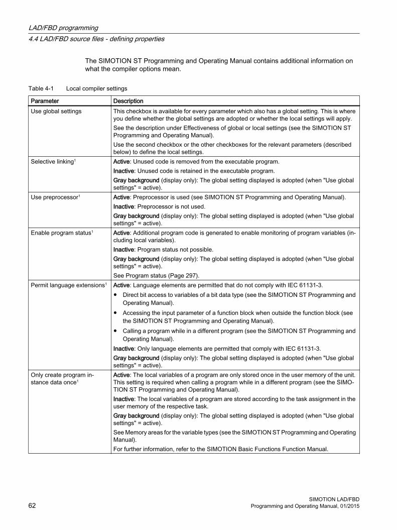
The SIMOTION ST Programming and Operating Manual contains additional information on what the compiler options mean.
Table 4-1 Local compiler settings
Parameter DescriptionUse global settings This checkbox is available for every parameter which also has a global setting. This is where
you define whether the global settings are adopted or whether the local settings will apply.See the description under Effectiveness of global or local settings (see the SIMOTION ST Programming and Operating Manual).Use the second checkbox or the other checkboxes for the relevant parameters (described below) to define the local settings.
Selective linking1 Active: Unused code is removed from the executable program.Inactive: Unused code is retained in the executable program.Gray background (display only): The global setting displayed is adopted (when "Use global settings" = active).
Use preprocessor1 Active: Preprocessor is used (see SIMOTION ST Programming and Operating Manual).Inactive: Preprocessor is not used.Gray background (display only): The global setting displayed is adopted (when "Use global settings" = active).
Enable program status1 Active: Additional program code is generated to enable monitoring of program variables (in‐cluding local variables). Inactive: Program status not possible.Gray background (display only): The global setting displayed is adopted (when "Use global settings" = active).See Program status (Page 297).
Permit language extensions1 Active: Language elements are permitted that do not comply with IEC 61131-3.● Direct bit access to variables of a bit data type (see the SIMOTION ST Programming and
Operating Manual).● Accessing the input parameter of a function block when outside the function block (see
the SIMOTION ST Programming and Operating Manual).● Calling a program while in a different program (see the SIMOTION ST Programming and
Operating Manual).Inactive: Only language elements are permitted that comply with IEC 61131-3.Gray background (display only): The global setting displayed is adopted (when "Use global settings" = active).
Only create program in‐stance data once1
Active: The local variables of a program are only stored once in the user memory of the unit. This setting is required when calling a program while in a different program (see the SIMO‐TION ST Programming and Operating Manual).Inactive: The local variables of a program are stored according to the task assignment in the user memory of the respective task.Gray background (display only): The global setting displayed is adopted (when "Use global settings" = active).See Memory areas for the variable types (see the SIMOTION ST Programming and Operating Manual).For further information, refer to the SIMOTION Basic Functions Function Manual.
LAD/FBD programming4.4 LAD/FBD source files - defining properties
SIMOTION LAD/FBD62 Programming and Operating Manual, 01/2015

Parameter DescriptionIssue warningsWarning classes1
In addition to error messages, the compiler can issue warnings and information. You can set the scope of the warning messages to be issued."Issue warnings" checkbox:Active: The compiler issues the warnings and information according to the warning class selection that follows.Inactive: The compiler suppresses all warnings and information concerning this source file. The checkboxes for the warning classes are hidden.Gray background (display only): Operating on a global setting basis, the compiler always issues warnings and information in accordance with the global warning class selection shown below (if "Use global settings" = active)."Warning classes" checkboxes (only if "Issue warnings" = active):Active: The compiler issues warnings and information for the selected class.Inactive: The compiler suppresses warnings and information for the respective class.Gray background (display only): The global setting displayed is adopted (when "Use global settings" = active).See also Meaning of warning classes (see the SIMOTION ST Programming and Operating Manual).
Permit forward declarations Forward declarations enable you to use program organization units (POUs) before they are completely defined. See the SIMOTION ST Programming and Operating Manual.This setting is always active. Forward declarations are always permitted for the LAD/FBD programming language.
Enable OPC-XML Active: Symbol information for the unit variables of the LAD/FBD unit is available in the SI‐MOTION device.This is required for:● The _exportUnitDataSet and _importUnitDataSet functions; see the SIMOTION Basic
Functions Function Manual● The watch function of IT DIAGInactive: Symbol information is not created.
Do not recompile source if global compiler settings have been changed
Active: The global settings of the compiler have no effect for all parameters. The "Use global settings" checkboxes cannot be selected and are grayed out. When changing the global compiler settings, the LAD/FBD source is not recompiled.Inactive: The "Use global settings" checkboxes can be selected for all parameters and are displayed with a white background. These checkboxes specify whether the global properties are taken over for the corresponding parameters.See the description under Effectiveness of global or local settings (see the SIMOTION ST Programming and Operating Manual).
1 Global setting is also possible ( Options > Settings > Compiler menu), see Global compiler settings (Page 60). See also the description on Effectiveness of global or local compiler settings (see the SIMOTION ST Programming and Operating Manual).
LAD/FBD programming4.4 LAD/FBD source files - defining properties
SIMOTION LAD/FBDProgramming and Operating Manual, 01/2015 63

4.5 Managing LAD/FBD programsLAD/FBD programs are the individual program organization units (program, function, function block) in a LAD/FBD source file. They are stored under the LAD/FBD source file in the project navigator.
4.5.1 Inserting a new LAD/FBD programYou can insert a new LAD/FBD program as program organization unit (POU) for an existing LAD/FBD source as follows (see Inserting a new LAD/FBD source (Page 48)):
● In the project navigator: Below an LAD/FBD unit using the element Insert LAD/FBD program
● Select the required LAD/FBD unit in the project navigator followed by Insert > Program > LAD/FBD program
● Open the required LAD/FBD unit and select the Insert LAD/FBD program icon in the LAD/FBD unit toolbar
ProcedureTo insert a new LAD/FBD program, proceed as follows:
1. Open the appropriate SIMOTION device in the project navigator.
2. Open the PROGRAMS folder and a LAD/FBD unit.
3. Double-click the entry Insert LAD/FBD program.
4. Enter the name of the program in the Insert LAD/FBD program dialog box.Names for LAD/FBD programs must comply with the Rules for identifiers (Page 99): They are made up of letters (A … Z, a … z), numbers (0 … 9), or single underscores (_) in any order, whereby the first character must be a letter or underscore. No distinction is made between uppercase and lowercase letters. Protected or reserved identifiers (Page 362) are not allowed.The permissible length of the name is 25 characters.The names must be unique within the LAD/FBD source. The names of all exportable program organization units (POUs) must also be unique within the SIMOTION device. The names of all LAD/FBD programs of the program source as well as the names of all exportable POUs of the device are displayed.
5. Select Program, Function, or Function block as the Creation type. See also Changing the LAD/FBD program creation type (Page 71).
6. For the Function creation type only:Select Return value data type as the Return type(<--> for no return value).
7. Activate the Exportable checkbox if you want the LAD/FBD program to be accessible from other program sources (LAD/FBD unit, MCC source files, or ST source files) or from the execution system.
8. You can also enter an author, version, and a comment.
LAD/FBD programming4.5 Managing LAD/FBD programs
SIMOTION LAD/FBD64 Programming and Operating Manual, 01/2015

9. Activate the Open editor automatically checkbox.
10.Click OK to confirm.
Note
When you click OK, the LAD/FBD program is transferred to the project only. The data is only saved to the data carrier, together with the project, if you select, for example, Project > Save, Project > Save and compile changes, or Project > Save and recompile all.
Figure 4-6 Insert LAD/FBD program dialog box
LAD/FBD programming4.5 Managing LAD/FBD programs
SIMOTION LAD/FBDProgramming and Operating Manual, 01/2015 65

① Name of the LAD/FBD unit② Name of the LAD/FBD program
Figure 4-7 Displaying the unit and program name in the project navigator
4.5.2 Opening an existing LAD/FBD programAll LAD/FBD programs belonging to an LAD/FBD unit are located in the project navigator underneath the LAD/FBD unit.
ProcedureTo open an available program, proceed as follows:
1. Open the subtree of the appropriate SIMOTION device in the project navigator.
2. Open the PROGRAMS folder.
3. Open the LAD/FBD unit containing the required LAD/FBD program.
4. Select the required LAD/FBD program.
5. Select the Open context menu.
6. Only for programs below LAD/FBD units with know-how protection (Page 53):If the LAD/FBD unit (or a program of this unit) is not already open and the login assigned to the LAD/FBD unit is not yet logged in:
– Enter the corresponding password for the displayed login.The know-how protection for this unit is temporarily canceled (until the unit and all its programs are closed).
– If required, activate the "Use login as a standard login" checkbox.You will be logged in with this login and can now open additional units to which the same login is assigned without having to re-enter the password.
LAD/FBD programming4.5 Managing LAD/FBD programs
SIMOTION LAD/FBD66 Programming and Operating Manual, 01/2015

The LAD/FBD program opens in the working area. Several LAD/FBD programs can be opened at the same time.
Note
You can also double-click the required LAD/FBD program to open it.
4.5.3 Defining the order of the LAD/FBD programs in the LAD/FBD source fileAs of Version V4.2 of SIMOTION SCOUT, the user no longer needs to respect the POU order in the LAD/FBD unit, as this no longer has any role to play in terms of compilability. The user may wish to change the POU order so that the POUs are arranged in a more logical way from his or her own perspective.
ExceptionWhen a project is saved in a format older than Version V4.2 of SIMOTION SCOUT, the order of the LAD/FBD programs in the LAD/FBD source file is of relevance as far as compilation is concerned. A subroutine (function, function block, or program ("program in program")) must be defined before it is used. This is the case when the LAD/FBD program of the subroutine appears in the project navigator above the LAD/FBD program in which it is used. If necessary, reorder the charts (see Subroutine call of function (FC) (Page 172)).
Prior to saving a project in a project format earlier than version 4.2, you can test the project for downward compatibility (i.e. the correct POU order, etc.) via Project > Old project format > Test the project for downward compatibility.
ProcedureTo change the order:
1. Select a LAD/FBD program in the project navigator.
2. In the context menu, select Up / Down
4.5.4 Copying the LAD/FBD programTo copy a LAD/FBD program:
1. In your LAD/FBD unit, select the POU you want to copy.
2. In the context menu, select Copy.
3. Select the LAD/FBD unit which is to be inserted in the POU.
4. In the context menu, select Insert.The LAD/FBD program is inserted.
LAD/FBD programming4.5 Managing LAD/FBD programs
SIMOTION LAD/FBDProgramming and Operating Manual, 01/2015 67

4.5.5 Saving and compiling a LAD/FBD programAn asterisk is appended in the title bar of the project to the name of a program which has been modified but not yet saved.
Note
The entire unit and its POUs are saved and compiled
To save the LAD/FBD program and start the compilation:
1. Click the Save and compile icon in the LAD/FBD editor toolbar.- or -Select the LAD/FBD program > Save and compile menu item.- or -Select the LAD/FBD program in the project navigator and select Save and compile in the context menu.- or -Shortcut Ctrl+B.- or -If you want to save and compile all the available LAD/FBD programs, select the Project > Save and compile changes menu command.If any errors occur during compilation, the error locations are displayed in the Detail view.
2. To fix an error, double-click an error message in the detail view in the Compile / check output tab.The faulty element is selected and positioned in the window.
NoteBackward compatibility
This SCOUT program version supports structures (e.g. several POUs in one unit, advance binary switching) which may not be able to be processed by previous versions.
4.5.6 Closing a LAD/FBD programTo close a LAD/FBD program opened in the working window, proceed as follows:
1. Click the x button (cross) in the title bar of the dialog box of the LAD/FBD program.- or -Select the LAD/FBD program > Close menu item.- or -Select the Windows > Close all menu item.- or -Shortcut Ctrl+F4.If the changes have not yet been saved, you can save or cancel them, or abort the close operation.
LAD/FBD programming4.5 Managing LAD/FBD programs
SIMOTION LAD/FBD68 Programming and Operating Manual, 01/2015

4.5.7 Deleting the LAD/FBD programTo delete a LAD/FBD program:
1. In the project navigator, select the required LAD/FBD program.
2. In the context menu, select Delete.
Note
It is not possible to insert a LAD/FBD program that has been deleted.
LAD/FBD programming4.5 Managing LAD/FBD programs
SIMOTION LAD/FBDProgramming and Operating Manual, 01/2015 69

4.6 LAD/FBD programs - defining propertiesThe properties of a LAD/FBD program are specified when it is inserted.
However, these properties can be viewed and modified by doing the following:
1. Open the PROGRAMS folder under the SIMOTION device in the project navigator.
2. Open the required LAD/FBD unit.
3. Select the required LAD/FBD program.
4. From the context menu, select Properties.The LAD/FBD program properties dialog box opens.
Figure 4-8 Properties of an LAD/FBD program
4.6.1 Renaming a LAD/FBD programTo rename a LAD/FBD program:
1. Open the property view for the LAD/FBD program.
2. Click .
LAD/FBD programming4.6 LAD/FBD programs - defining properties
SIMOTION LAD/FBD70 Programming and Operating Manual, 01/2015
3. Confirm the message with OK and enter the new name in the New name input field of the Change Name dialog box.
4. Acknowledge the entries with Apply.
4.6.2 Changing the LAD/FBD program creation typeTo change the LAD/FBD program creation type:
1. Select the new creation type:ProgramPrograms can be compared with function blocks. Local variables can be stored here either statically or temporarily. In contrast to FBs or FCs, programs can be assigned to a task or an execution level in SIMOTION SCOUT. Programs cannot be called up with parameters. Therefore, unlike FBs and FCs, programs do not have any formal parameters.Function block (FB)A function block (FB) is a program with static data, i.e. all local variables retain their values after the function block has been executed. Only variables explicitly declared as temporary variables lose their value between two calls.Before an FB is used, an instance must be defined: Define a variable (VAR or VAR_GLOBAL) and enter the name of the FB as data type. The FB static data is saved in this instance. You can define multiple instances of an FB, with each instance being independent of the others.The static data of an FB instance are retained until the next time the instance is called; the static data are reinitialized when the variable type of the FB instance is reinitialized.Data transfer to the FB takes place via input or input/output parameters, and the data return from the FB takes place via input/output parameters or output parameters.Function (FC)A function (FC) is a function block without static data, that is, all local variables lose their value when the function has been executed. They are reinitialized the next time the function is started.Data transfer to the function takes place by means of input parameters; output of a function value (return value) is possible.
LAD/FBD programming4.6 LAD/FBD programs - defining properties
SIMOTION LAD/FBDProgramming and Operating Manual, 01/2015 71

4.7 Printing source files and programsYou can print general information about the LAD/FBD source files and programs. Various print options can be set for the printout.
To print LAD/FBD units and programs, proceed as follows:
1. Select a LAD/FBD source file or program in the project navigator.
2. From the context menu, select Print or Print preview.The Print dialog box will appear, enabling you to set various print options.
Figure 4-9 Dialog box for setting print options
3. Click the Print button.The source file or LAD/FBD program is printed with the selected options. General information, the declaration table and diagram all appear in the printout.
4.7.1 Printing a declaration tableTo print a declaration table, proceed as follows:
1. Activate the Print declaration table check box.
2. Select Column widths by screen.The contents of the declaration table are printed with the set column widths.- or -Select Default column widths.
LAD/FBD programming4.7 Printing source files and programs
SIMOTION LAD/FBD72 Programming and Operating Manual, 01/2015
4.7.2 Printing a network areaTo print a network area, proceed as follows:
1. Activate the Print network area check box.
2. Select All networks.- or -Select Selected networks only.Prints only the networks selected in the editor (blue selection mark on the left side).
4.7.3 Printing commentsYou can only select this option if you have already selected the Print network area option.
To print comments, proceed as follows:
1. Activate the Print comments check box.
2. To obtain a shorter, more concise print image, unselect the Print comments option.
4.7.4 Defining print variantsTo define the print variant, proceed as follows:
1. Activate the check box.
2. Select Scale graphics to page width.The print image is scaled so that the widest LAD/FBD network fits on one page width. The print image is one page in width and one or more pages in length, depending on the size of the program.- or -Select Scale graphics to page height.The print image is scaled so that the entire graphic fits on one page height. The print image is one page in length and takes up one or more page widths, depending on the width of the networks.- or -Select Scale graphics to one page.The print image is reduced so that all networks fit on one page.- or -Select Graphic at 100%.The image is printed in its original size. The print image can consist of more than one page vertically or horizontally.- or -Select Save screen zoom factor.The image is printed according to the zoom factor set in the editor. The print image can consist of more than one page vertically or horizontally.
Note
If the print image consists of more than one page, an index page is printed to give an overview.
LAD/FBD programming4.7 Printing source files and programs
SIMOTION LAD/FBDProgramming and Operating Manual, 01/2015 73

4.7.5 Placing networksWith Placing networks you define how the networks are distributed over the pages for printing.
To place networks, proceed as follows:
1. Activate the Place networks check box.
2. Select Continuous.The networks are printed one after another. Page breaks are not taken into account in this case.- or -Select All on new page.All networks are printed beginning on a new page. If a network is longer than one page, it is printed on the next page.- or -Select Optimized.This minimizes the horizontal break between networks to save more space. E.g.: If a network does not fit on the current page and is not longer than one page, this network will be printed on the next page. If the network is longer, then a page break must be inserted.
4.7.6 Blank pagesYou can select how blank pages are printed out. The layout is displayed on the index page. Pages marked with an X are omitted.
To set the printing of blank pages, proceed as follows:
1. Activate the Blank pages checkbox.
2. Select Print all.All blank pages are printed.- or -Select Omit at end.Blank pages at the end are not printed. Blank pages in the middle are retained.- or -Select Omit all.Blank pages in the middle and at the end are omitted.
LAD/FBD programming4.7 Printing source files and programs
SIMOTION LAD/FBD74 Programming and Operating Manual, 01/2015

4.8 LAD/FBD networks and elementsThe LAD/FBD program is organized in networks which are displayed in the editor area. A network contains a logic circuit representing the ladder diagram line.
The rules for the structure of a network according to IEC standard 61131-3 apply to the display of a network. Several LAD/FBD elements and boxes can be inserted, copied or deleted in a network.
Note
Use the key combinations (Page 32)for fast operation in the LAD/FBD editor.
① Name of program and comment field ⑤ Network 2② Call box ⑥ Selected LAD element③ LAD element ⑦ Name of network and comment field④ Network 1 ⑧ Selected network
Figure 4-10 Display of the networks in the LAD/FBD editor
See alsoNumbering the networks (Page 77)
LAD/FBD programming4.8 LAD/FBD networks and elements
SIMOTION LAD/FBDProgramming and Operating Manual, 01/2015 75

4.8.1 Inserting networksTo paste in a network:
1. Select an existing network or click in the working window of the open LAD/FBD program.
2. From the context menu, select Insert network.- or -Select LAD/FBD program > Insert network.- or -Click the Insert network icon.The new network is pasted in directly after the network which is currently selected. If no network is selected, the new network is pasted in at the front.
See alsoLAD/FBD networks and elements (Page 75)
4.8.2 Selecting networksThe relevant networks have to be selected before they can be copied.
To select networks:
1. Select the desired network.The network is selected (see figure).- or -If you want to select several adjacent networks, click the first required network and then, keeping the Shift key depressed, click the last one required.- or -If you want to select several networks which are not adjacent to one another, hold the Ctrl key down and click each network you need.
Selected networks are indicated by a light blue edge on their left-hand side. You can choose the selection color in the LAD/FBD editor tab of the Settings dialog box.
Figure 4-11 Selected network
LAD/FBD programming4.8 LAD/FBD networks and elements
SIMOTION LAD/FBD76 Programming and Operating Manual, 01/2015

See alsoSettings in the LAD/FBD editor (Page 38)
4.8.3 Numbering the networksWhen a network is pasted in, it is automatically given the next consecutive number. This number is unique and is used to identify the network.
Note
You cannot change the numbering. When a network is deleted, the numbering is automatically adjusted.
See alsoLAD/FBD networks and elements (Page 75)
4.8.4 Enter title/comment
Titles and comments By default, the LAD/FBD program and/or the network contain a title and a comment field. The title and comment texts are language-dependent.
Language-dependent textsYou can use the Project > Language-dependent texts menu item to import and export ASCII files containing translations of LAD/FBD network comments and symbol browser comments (I/O variables, global device variables).
The exported files (Export button) can be re-imported into the project using the import function (Import button) once they have been translated.
After a language change, the user-defined comments in the project are available in the respective compiled languages.
Assigning a titleThe title/name is used for the documentation of the LAD/FBD program or network. It is initialized with the name "Title".
LAD/FBD programming4.8 LAD/FBD networks and elements
SIMOTION LAD/FBDProgramming and Operating Manual, 01/2015 77

To enter a title, proceed as follows:
1. Click in the title line.
2. Enter a different title/name in the window which appears.There is no maximum text length. The length of text visible on the screen depends on the font, font size and screen resolution.
Entering/modifying commentsYou can enter a comment in every program or network.
To enter a comment, proceed as follows:
1. Click in the comment line.
2. Enter the text of the comment in the window which appears.
3. To change an existing comment, double-click the existing comment.
4. Overwrite the now selected text.
Showing/hiding a comment lineIn every program/network, you can hide a comment that has been entered:
To hide and show comments, proceed as follows:
1. Click in the working window of the open LAD/FBD program.
2. From the context menu, select Display > Comments on/off.- or -Select the LAD/FBD program > Display > Comments on/off menu item.- or -Shortcut Ctrl+Shift+K.
This change always applies to the active LAD/FBD editor. The setting is only saved when saving if changes have been made in the respective editor window.
4.8.5 Showing/hiding a jump labelYou can paste a jump label in every network.
To paste in or hide jump labels, proceed as follows:
1. Select the network in which the jump label is to be pasted.
2. From the network context menu, select Jump label ON/OFF.
LAD/FBD programming4.8 LAD/FBD networks and elements
SIMOTION LAD/FBD78 Programming and Operating Manual, 01/2015
3. Enter the text of the jump label in the window that appears.Only alphanumeric characters and underscores are allowed during input. The text length of a label must not exceed 480 characters.
Note
The jump label is deleted if it contains an error and cannot be corrected.
4. If you want to hide a jump label, select the required jump label and select Jump label ON/OFF in the context menu.
See alsoOverview of jump operations (Page 251)
4.8.6 Copying/cutting/pasting networksIf a network is copied or cut, and then pasted in again, all LAD/FBD elements in the network are taken with it.
To copy a network, proceed as follows:
1. Select the required network.
2. In the context menu, select Copyor Cut.- or -Select the Edit > Copy or Edit > Cut menu item.The copied network can be pasted again at any place or even in other LAD/FBD programs.A new/copied or cut network is always pasted in after the selected network. If no network is selected, the new network is placed as the first network.
4.8.7 Undo/redo actions
Note
The following actions cannot be undone:
- Save
- Save and compile
To undo or redo actions, proceed as follows:
1. Select the Edit > Undo menu command or the Undo symbol.The actions are undone in reverse order.
2. If you want to redo one or more undone actions, select the Edit > Redo menu item or the Redo icon.
LAD/FBD programming4.8 LAD/FBD networks and elements
SIMOTION LAD/FBDProgramming and Operating Manual, 01/2015 79

4.8.8 Deleting networksTo delete a network:
1. Click in a network in the open LAD/FBD program.
2. From the context menu, select Delete network.
LAD/FBD programming4.8 LAD/FBD networks and elements
SIMOTION LAD/FBD80 Programming and Operating Manual, 01/2015

4.9 Displaying LAD/FBD elements
4.9.1 LAD diagram
LAD diagram The LAD diagram complies with Standard IEC 61131-3 and is organized around the binary ladder diagram line. The ladder diagram line begins with a vertical line (conductor bar) and ends with a coil, call-up (box) or with a jump to another network. In between, there are special LAD elements (NO contacts, NC contacts, connectors), general logical elements (SR, RS flipflop), system components call-ups (e.g arithmetic operations), and user functions or function blocks.
Rules for entering LAD statements ● Start of a LAD network
The left conductor bar is the network's starting point. Crossed lines are not permitted in a LAD diagram. The following elements are not permitted at the beginning of a network: (P), (N), (#).
● LAD network terminationEvery LAD network must terminate with a coil or a box. Multiple outputs are possible.The following LAD elements may not be used to terminate a network:
– (P),
– (N),
– POS,
– NEG,
– Comparator.
● Placement of empty boxesEmpty boxes can be placed anywhere in a network except on the right-hand edge or in a parallel branch. Preconnection at binary inputs is supported.
● Placement of coilsCoils are automatically placed on the right-hand edge of the network, where they are used to terminate a branch.
LAD/FBD programming4.9 Displaying LAD/FBD elements
SIMOTION LAD/FBDProgramming and Operating Manual, 01/2015 81

● Parallel branchesParallel branches are
– opened downward and closed upward.
– opened behind the selected LAD element.
– closed behind the selected LAD element.
Another branch can be inserted between two parallel branches. To delete a parallel branch, you must delete all LAD elements of this branch. When the last LAD element is removed from the branch, the rest of the branch is also removed. The following elements are not permitted in the parallel branch:
– (P),
– (N),
– (#),
– Empty box.
The following elements are permitted in the parallel branch:
– Contacts,
– Comparators,
– Edge detection (POS, NEG).
Parallel branches which branch directly off the power rail are an exception to these placement rules: All elements can be placed in these branches.
● Constants and enumsBinary operations can also be assigned constants (e.g. TRUE or FALSE). FB/FC parameters can be connected with constants that reflect the parameter data type.If a parameter is connected with an enum value that is not unique project-wide, preface the enum value with the enum type separated by #.
4.9.2 Meaning of EN/ENO
Enable input (EN) and enable output (ENO) of the LAD boxThe LAD box enable input (EN) and enable output (ENO) parameters function according to the following principles:
● If EN is not enabled (i.e., the signal is set to "0"), then the box will not execute its function, and ENO is not enabled (i.e., the signal is also "0").
● If EN is enabled (i.e., the signal is set to "1"), then the appropriate box executes its function, and then ENO is also enabled (i.e., the signal is also "1").
LAD/FBD programming4.9 Displaying LAD/FBD elements
SIMOTION LAD/FBD82 Programming and Operating Manual, 01/2015

4.9.3 FBD diagram
FBD diagram An FBD diagram complies with IEC standard 61131-3.The main binary signal line begins with a logic box (top left) and ends with an assignment, call (box), or with a jump to another network. In between, there are logic elements (AND, OR box), general logic elements (SR, RS flip-flop), system component call-ups (e.g. arithmetic operations), and user function or function block call-ups.
Rules for entering FBD statements ● Placement of boxes
Empty boxes (flipflops, counters, timers, arithmetic operations, device-specific commands, TO-specific commands, etc.) can be attached to boxes with binary connections (&, =1, XOR).Preconnections on binary inputs (e.g. S input on flipflop) are allowed.Separate connections with separate outputs cannot be programmed in a network. Junctions are not supported.
Figure 4-12 FBD with binary preconnection
● &, >=1, XOR boxesBinary inputs can be inserted, deleted, or negated in these boxes.
● Enable input/enable outputConnection of the enable input EN and/or the enable output ENO of boxes is possible.
● Constants and enumsBinary operations can also be assigned constants (e.g. TRUE or FALSE). FB/FC parameters can be connected with constants that reflect the parameter data type.If a parameter is connected with an enum value that is not unique project-wide, preface the enum value with the enum type separated by #.
LAD/FBD programming4.9 Displaying LAD/FBD elements
SIMOTION LAD/FBDProgramming and Operating Manual, 01/2015 83

4.9.4 Converting between LAD and FBD representation
Converting from LAD to FBD representationTo switch from LAD to FBD representation, proceed as follows:
1. Open an existing LAD project.
2. Select the LAD/FBD program > Switch to FBD menu item.- or -Click the button for "Switch to FBD" (Ctrl+3 shortcut) in the LAD editor toolbar.The project is now displayed in the FBD programming language.
Figure 4-13 Switching from LAD to FBD
Note
A conversion sequence of LAD - FBD - LAD always produces the original network.
Anything generated in LAD can always be displayed in FBD.
LAD/FBD programming4.9 Displaying LAD/FBD elements
SIMOTION LAD/FBD84 Programming and Operating Manual, 01/2015
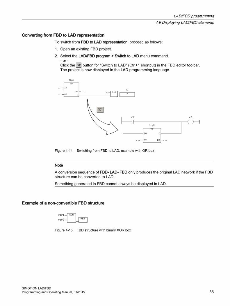
Converting from FBD to LAD representationTo switch from FBD to LAD representation, proceed as follows:
1. Open an existing FBD project.
2. Select the LAD/FBD program > Switch to LAD menu command.- or -Click the button for "Switch to LAD" (Ctrl+1 shortcut) in the FBD editor toolbar.The project is now displayed in the LAD programming language.
Figure 4-14 Switching from FBD to LAD, example with OR box
Note
A conversion sequence of FBD- LAD- FBD only produces the original LAD network if the FBD structure can be converted to LAD.
Something generated in FBD cannot always be displayed in LAD.
Example of a non-convertible FBD structure
Figure 4-15 FBD structure with binary XOR box
LAD/FBD programming4.9 Displaying LAD/FBD elements
SIMOTION LAD/FBDProgramming and Operating Manual, 01/2015 85

4.10 Editing LAD/FBD elements
4.10.1 Inserting LAD/FBD elementsLAD/FBD elements are usually inserted to the right of the selected position in the network.
FBD elements are usually inserted at a boolean input of a block or at an assignment (left).
Special case:
If the right-hand edge of a network or a coil (LAD) or an assignment (FBD) is selected, the next element is added in the network on the left-hand side of it.
To insert an LAD/FBD elements:
1. Select the position in a network behind which you want to insert an LAD/FBD element.
2. Insert an LAD/FBD element:
– Via the icons on the toolbar
– Using the menu item, e.g. LAD/FBD program > Insert element > Empty box
– With a drag and drop operation from the Command library tab
– By double-clicking the element in the Command library tab
– By selecting the element in the Command library tab and confirming with the Enter key
The selected LAD/FBD element is inserted and the placeholders and ... are inserted for variables and parameters.
Note
A red ??? symbol indicates mandatory parameters that must be connected.
A black ... character string indicates optional parameters that can be connected.
Move the cursor over the parameter name to display the expected data type.
4.10.2 Syntax check in LADAn automatic syntax check during input prevents the incorrect placement of elements.
● NOT in parallel branch
● FB/FC call in parallel branch
● Connector in parallel branch
● Check 0 -> 1 edge and 1 -> 0 edge in parallel branch
● XOR in parallel branch
LAD/FBD programming4.10 Editing LAD/FBD elements
SIMOTION LAD/FBD86 Programming and Operating Manual, 01/2015
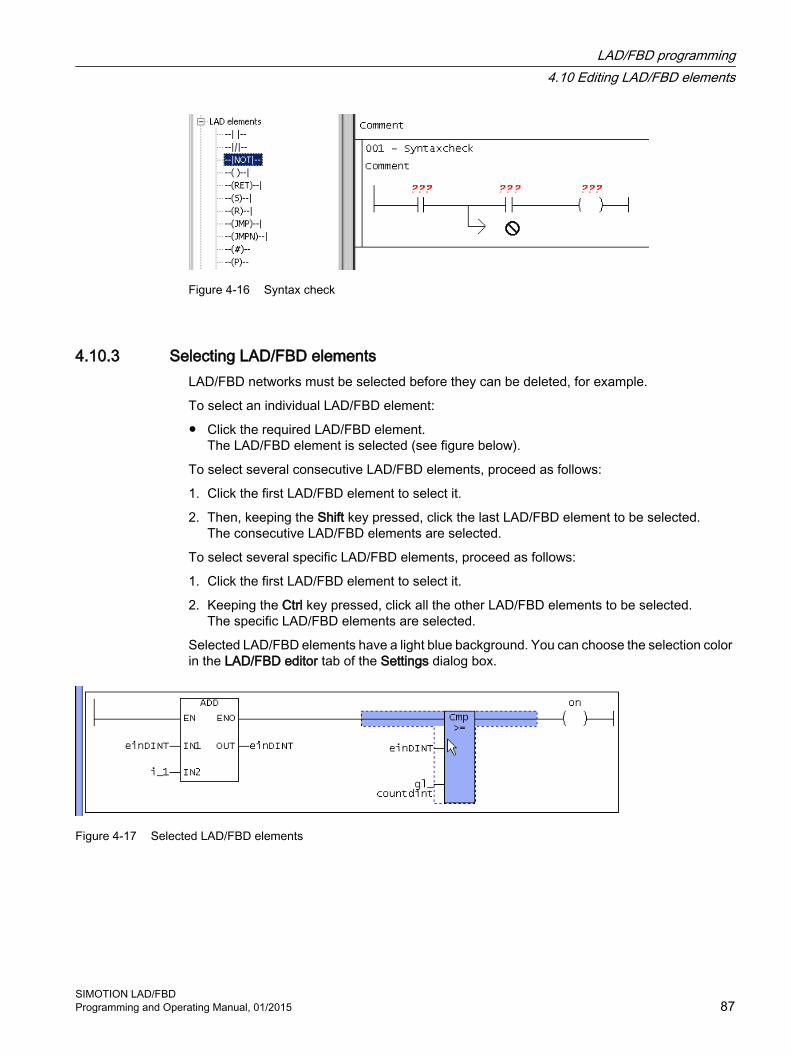
Figure 4-16 Syntax check
4.10.3 Selecting LAD/FBD elementsLAD/FBD networks must be selected before they can be deleted, for example.
To select an individual LAD/FBD element:
● Click the required LAD/FBD element.The LAD/FBD element is selected (see figure below).
To select several consecutive LAD/FBD elements, proceed as follows:
1. Click the first LAD/FBD element to select it.
2. Then, keeping the Shift key pressed, click the last LAD/FBD element to be selected.The consecutive LAD/FBD elements are selected.
To select several specific LAD/FBD elements, proceed as follows:
1. Click the first LAD/FBD element to select it.
2. Keeping the Ctrl key pressed, click all the other LAD/FBD elements to be selected.The specific LAD/FBD elements are selected.
Selected LAD/FBD elements have a light blue background. You can choose the selection color in the LAD/FBD editor tab of the Settings dialog box.
Figure 4-17 Selected LAD/FBD elements
LAD/FBD programming4.10 Editing LAD/FBD elements
SIMOTION LAD/FBDProgramming and Operating Manual, 01/2015 87

4.10.4 Copy/cut/delete operations in LAD/FBD elementsTo copy/cut/delete, proceed as follows:
1. Select a LAD/FBD element.
2. In the context menu or in the Edit menu, select e.g. Copy.The copied/cut LAD/FBD element can be inserted into other LAD/FBD programs.If you delete an FB/FC box with binary preconnections, this results in several open branches (in LAD) or sub-networks (in FBD) which can be further connected.
4.10.5 LAD/FBD elements - defining parameters (labeling)To label the elements, proceed as follows:
1. Click the parameter.
2. Label the parameter:
– Select the corresponding parameter from the pull-down menu (for box-type only).- or -
– Enter the appropriate variable.- or -
– Drag the corresponding variable from the declaration table using a drag-and-drop operation.
3. Confirm the entry with the Return key.
See alsoSetting call parameters (Page 90)
Defining variables in the Variable declaration dialog box ("on-the-fly" variable declaration) (Page 118)
4.10.6 Labeling LAD/FBD elements with the symbol input help dialogTo label the element with the Symbol input help, proceed as follows:
1. Select the parameter you want to label.
2. Right-click to open the context menu.
3. Click the Symbol input help menu.- or -Call the symbol input help with the key shortcut Ctrl+Alt+H.The Symbol input help dialog box opens. The tree structure shows all variables which exist in the project and which can be used.
4. Select the desired variable and click OK to confirm.The label is entered in the selected parameter. If the variable is defined in another program source or in a library, a Connection (Page 162) is created automatically.
LAD/FBD programming4.10 Editing LAD/FBD elements
SIMOTION LAD/FBD88 Programming and Operating Manual, 01/2015

4.10.7 Setting the LAD/FBD element displayIn order to ensure a manageable view of relatively large call boxes, you can set the display mode of LAD/FBD elements.
To set the LAD/FBD element display, proceed as follows:
1. Click in the editor area of the LAD/FBD program.
2. Select the required display mode:
– In the context menu, select View > No box parameters or the LAD/FBD program > View > No box parameters menu item.- or -
– In the context menu, select View > Only assigned box parameters or the LAD/FBD program > View > Only assigned box parameters menu item.- or -
– In the context menu, select View > Mandatory and assigned box parameters or the LAD/FBD program > View > Mandatory and assigned box parameters menu item.- or -
– In the context menu, select View > All box parameters or the LAD/FBD program > View > All box parameters menu item.This box parameter setting is also saved when storing.
Note
If a call box has non-represented parameters, this is indicated by ... at the bottom of the box.
4.10.8 Setting the call parameter for an individual parameterTo set an individual call parameter, proceed as follows:
1. Double-click the parameter input/output you want to set.The Enter call parameter for individual parameter dialog box appears.
Figure 4-18 Dialog box for setting an individual call parameter
2. Assign a variable or value to the parameter from the Values list.
3. Confirm your selection twice with the Enter key to close the dialog box again.
LAD/FBD programming4.10 Editing LAD/FBD elements
SIMOTION LAD/FBDProgramming and Operating Manual, 01/2015 89

4.10.9 Setting call parametersTo set the call parameters, proceed as follows:
1. Label the type parameters of the box.
2. Double-click the box.- or -In the context menu, select Call parameters ....The Enter call parameters dialog box appears.Only variables which have already been declared and symbols/variables offered by the system are displayed.
Figure 4-19 Dialog box for setting call parameters
LAD/FBD programming4.10 Editing LAD/FBD elements
SIMOTION LAD/FBD90 Programming and Operating Manual, 01/2015

3. Enter:
– Return valueHere you assign the function return value to a variable of the calling program.
– InstanceHere, you enter the instance of the function block.
– ValueHere, you can assign current variables or values to the parameters.
4. Confirm with OK.
Note
The Value list includes all symbols which are visible in the current target (variables, enum values, etc.) whose type matches the data type of the parameter. Implicit data type conversion is taken into consideration here. You can select a symbol from the list or type one in yourself.
The value of string constants must be entered in inverted commas (e.g. 'st_until')
LAD/FBD programming4.10 Editing LAD/FBD elements
SIMOTION LAD/FBDProgramming and Operating Manual, 01/2015 91

4.11 Command library
4.11.1 LAD/FBD functions in the command libraryThe command library appears automatically as a tab in the project navigator. The command library stays open after the programming window is closed.
Figure 4-20 Command library tab of the project navigator
LAD/FBD programming4.11 Command library
SIMOTION LAD/FBD92 Programming and Operating Manual, 01/2015

4.11.2 Inserting elements/functions from the command libraryTo paste elements/functions into a programming window:
1. Left-click the desired function in the command library, drag the function onto the editor window while keeping the left mouse button depressed and then release the left mouse button.- or -Double-click the desired function.- or -Select the desired function and press the Enter key.
LAD/FBD elements are usually pasted in to the right of the selected position in the network. FBD elements are usually pasted in at a boolean input of a block or at an assignment (left).
4.11.3 Description of PLCopen blocksPLCopen blocks are preferably used for the programming of motion control tasks in the LAD/FBD programming language. The PLCopen blocks are intended for use in cyclic programs/tasks.
The following standard function blocks are available in the command library in SIMOTION. They are certified in accordance with "PLCopen Compliance Procedure for Motion Control Library V1.1".
The details and the use of the PLCopen blocks are described in the PLCopen Blocks Function Manual.
An example for the use of the PLCopen blocks is contained in Section "Positioning axis program (Page 341)".
Table 4-2 Single-axis function blocks for the axis
Function block Description_MC_Power() Enabling/disabling axis_MC_Stop() Stopping the axis_MC_Home() Homing axis/clearing absolute value encoder offset_MC_MoveAbsolute() Absolutely positioning axis_MC_MoveRelative() Relatively positioning axis_MC_MoveVelocity() Traversing axis at defined velocity_MC_MoveAdditive() Positioning relative to current target position (traversing axis using
an additional, defined path, relative to current position setpoint)_MC_MoveSuperimposed() Superimposed positioning (traversing axis relative to current mo‐
tion)_MC_PositionProfile() Traveling through position/time profile (traversing axis along a
predefined, fixed position/time profile)_MC_VelocityProfile() Traveling through velocity/time profile (traversing axis along a
predefined, fixed velocity/time profile)Basic functions_MC_Reset() Resetting errors/alarms on the axis or triggering a restart_MC_ReadActualPosition() Reading the actual position of axis
LAD/FBD programming4.11 Command library
SIMOTION LAD/FBDProgramming and Operating Manual, 01/2015 93

Function block Description_MC_ReadStatus() Reading the status of an axis_MC_ReadAxisError() Reading the error of an axis_MC_ReadParameter() Reading axis parameter and outputting in data type LREAL_MC_ReadBoolParameter() Reading axis parameter and outputting in data type BOOL_MC_WriteParameter() Writing axis parameter of data type LREAL_MC_WriteBoolParameter() Writing axis parameter of data type BOOLIn addition to the standard function blocks, the following function block is available for an axis:_MC_Jog() Continuous or incremental jogging
Table 4-3 Multi-axis function blocks for the axis
Function Description_MC_GearIn() Starting gearing (synchronizing master and slave axis while tak‐
ing into account a positional relationship described by a fixed gear ratio)
_MC_GearOut() Terminating gearing (desynchronizing master and slave axis)_MC_CamIn() Starting camming (synchronizing master and slave axis while tak‐
ing into account a positional relationship described by a cam)_MC_CamOut() Terminating camming (desynchronizing master and slave axis)_MC_Phasing() Changing phase shift between the leading axis and following axis
Table 4-4 Function blocks for the external encoder
Function Description_MC_Power() Enabling external encoder_MC_Reset() Resetting external encoder_MC_Home() Homing external encoder_MC_ReadActualPosition() Reading actual position of external encoder_MC_ReadStatus() Reading external encoder status_MC_ReadAxisError() Reading external encoder error_MC_ReadParameter() Reading external encoder parameter and outputting in data type
LREAL_MC_ReadBoolParameter() Reading external encoder parameter and outputting in data type
BOOL
LAD/FBD programming4.11 Command library
SIMOTION LAD/FBD94 Programming and Operating Manual, 01/2015

4.11.4 Special features of the command library
Special featuresThe following ST commands have no corresponding function that can be used with LAD/FBD:
● BOOL := _checkequaltask([IN]TASK, [IN]TASK)Two StructTaskID or two StructAlarmID can be compared to one comparator.
● StructAlarmID := _getalarmid([IN]ALARM)These alarm commands can be found in the _alarm name space (_alarm.myalarm).
● StructTaskID := _gettaskid([IN]TASK id:=TaskIdThis)The task commands can be found in the _task name space (_task.backgroundtask).
Examples for parameters of type _alarmid and _starttaskid
Figure 4-21 Examples for StructAlarmID
Figure 4-22 Example for StructTaskID
LAD/FBD programming4.11 Command library
SIMOTION LAD/FBDProgramming and Operating Manual, 01/2015 95

4.12 General information about variables and data types
4.12.1 Overview of variable typesThe following table shows all the variable types available for programming with ST.
● System variables of the SIMOTION device and the technology objects
● Global user variables (I/O variables, device-global variables, unit variables)
● Local user variables (variables within a program, a function, or a function block)
System variables
Variable type MeaningSystem variables of the SI‐MOTION device
Each SIMOTION device and technology object has specific system variables. These can be accessed as follows:● Within the SIMOTION device from all programs● From HMI devicesYou can monitor system variables in the symbol browser.
System variables of technol‐ogy objects
LAD/FBD programming4.12 General information about variables and data types
SIMOTION LAD/FBD96 Programming and Operating Manual, 01/2015

Global user variables
Variable type MeaningI/O variables You can assign symbolic variable names to the I/O addresses of the SIMOTION device or
the peripherals. This allows you to have the following direct accesses to the I/O:● Within the SIMOTION device from all programs● From HMI devicesYou create these variables in the symbol browser after you have selected the I/O element in the project navigator.You can monitor I/O variables in the symbol browser.
Global device variables User-defined variables which can be accessed by all SIMOTION device programs and HMI devices.You create these variables in the symbol browser after you have selected the GLOBAL DE‐VICE VARIABLES element in the project navigator.Global device variables can be defined as retentive. This means that they will remain stored even when the SIMOTION device power supply is disconnected.You can monitor global device variables in the symbol browser.
Unit variables User-defined variables that all programs (programs, function blocks, and functions) can ac‐cess within a unit (source file).You declare these variables in the declaration table of the source file:● In the interface section:
These variables are exported and can be used in other units (e.g. ST source files, MCC source files, LAD/FBD source files) after a connection has been defined (Page 163). They are also available on HMI devices as standard.
● In the implementation section:You can only access these variables within the source file.
You can declare unit variables as retentive. This means that they will remain stored even when the SIMOTION device power supply is disconnected.You can monitor unit variables in the symbol browser.
Local user variables
Variable type Meaning User-defined variables that can only be accessed within the program/chart (program, func‐
tion, function block) in which they were defined.Variable of a program (pro‐gram variable)
Variable is declared in a program. The variable can only be accessed within this program. A differentiation is made between static and temporary variables:● Static variables are initialized according to the memory area in which they are stored.
Specify this memory area by means of a compiler option. By default, the static variables are initialized depending on the task to which the program is assigned (see SIMOTION Basic Functions Function Manual).You can monitor static variables in the symbol browser.
● Temporary variables are initialized every time the program in a task is called.Temporary variables cannot be monitored in the symbol browser.
LAD/FBD programming4.12 General information about variables and data types
SIMOTION LAD/FBDProgramming and Operating Manual, 01/2015 97

Variable type MeaningVariable of a function (FC variable)
Variable is declared in a function (FC). The variable can only be accessed within this function.FC variables are temporary; they are initialized each time the FC is called. They cannot be monitored in the symbol browser.
Variable of a function block (FB variable)
Variable is declared in a function (FB). The variable can only be accessed within this function block. A differentiation is made between static and temporary variables:● Static variables retain their value when the FB terminates. They are initialized only when
the instance of the FB is initialized; this depends on the variable type with which the instance of the FB was declared.You can monitor static variables in the symbol browser.
● Temporary variables lose their value when the FB terminates. The next time the FB is called, they are reinitialized.Temporary variables cannot be monitored in the symbol browser.
4.12.2 Scope of the declarations
Scope of variable and data type declarations according to location of declaration
Location of declaration What can be declared here ScopeSymbol browser ● Global device variables
● I/O variablesThe declared variables are valid in all units (e.g., ST source files, MCC source files, LAD/FBD source files) of the SIMOTION device. All programs, function blocks, and functions in all units of the device can ac‐cess the variables.
Interface section of the unit1 ● Unit variables● Data types● Symbolic accesses to the fixed
process image of the BackgroundTask
The declared variables, data types, etc., are valid in the entire unit (e.g., ST source file, MCC source file, LAD/FBD source file); all programs, function blocks, and functions within the unit can access them.In addition, they are also available in other units after connection (see Define connections (Page 163)).
Implementation section of the unit1
● Unit variables● Data types● Symbolic accesses to the fixed
process image of the BackgroundTask
The declared variables, data types, etc., are valid in the entire unit (e.g., ST source file, MCC source file, LAD/FBD source file); all programs, function blocks, and functions within the source file can access them.
POU (program/function block/function)2
● Local variables● Data types● Symbolic accesses to the fixed
process image of the BackgroundTask
The declared variables, data types, etc., can only be accessed within the POU in which they were declared.
1 MCC and LAD/FBD programming languages: in the declaration table of the respective source file.2 MCC and LAD/FBD programming languages: in the declaration table of the respective chart/program.
LAD/FBD programming4.12 General information about variables and data types
SIMOTION LAD/FBD98 Programming and Operating Manual, 01/2015

4.12.3 Rules for identifiersNames for variables, data types, charts/programs must comply with the following rules for identifiers:
1. They are made up of letters (A to Z, a to z), numbers (0 to 9), and underscores ( _ ).
2. The first character must be a letter or underscore.
3. This can be followed by as many letters, digits or underscores as needed in any order.
4. Exception: You must not use more than one underscore in succession.
5. Both upper- and lower-case letters are allowed. No distinction is made between upper- and lower-case notation (thus, for example, Anna and AnNa are regarded as identical).
NoteReserved identifiers
Reserved identifiers may only be used as predefined. You may not declare a variable or data type with the name of a reserved identifier.
There is no distinction between upper- and lower-case notation.
You can find a list of all the identifiers whose meanings are predefined in SIMOTION in the SIMOTION Basic Functions Function Manual.
NoteIdentifiers for SIMOTION devices
Identifiers for SIMOTION devices do not have to comply with rules specified above. When used in SIMOTION SCOUT they must be enclosed in double inverted commas (", ASCII code $22). See the SIMOTION ST Programming and Operating Manual.
4.12.4 Frequently used arrays in declarations
4.12.4.1 Array length and array elementA field is a chain of variables of the same type that can be addressed with the same name and different indices.
You can define the variable as a field [0...N-1] by entering a field length N.
You have the following options for entering the field length:
● You can enter a constant positive integer value.
● You can enter a value range with ".." separating the min. and max. values.
● You can enter a constant expression of data type DINT (or of a data type that is implicitly convertible to DINT).
If the field is empty, a single variable is set up rather than a field.
LAD/FBD programming4.12 General information about variables and data types
SIMOTION LAD/FBDProgramming and Operating Manual, 01/2015 99

Example definition of a field in the declaration table
Figure 4-23 Defining the length of a field
Example of use of field elements in a variable assignment
Figure 4-24 Use of field elements in a variable assignment
4.12.4.2 Initial valueYou can specify an initialization value in this column. You can specify this initialization value as a constant or an expression. The following are permissible:
● Constants
● Arithmetic operations
● Bit slice and data conversion functions
Variables of a technology object data type cannot be assigned an initialization value. They are always initialized by the compiler with TO#NIL.
Initialization of arraysPer default, the compiler assigns all array elements the initialization value of the data type. The initialization values can be changed by specifying an array initialization list according to the following example.
Table 4-5 Preassignment of array elements
10(1) 10 array elements [0..9] are pre-assigned the same value "1".1,2,3,4,5 5 array elements [0..4] are pre-assigned different values "1", "2", "3", "4" and
"5".5(3),10(99),3(7),2(1) The following array elements are pre-assigned the following values:
● Five array elements [0..4] with the same value "3".● 10 array elements [5..14] with the same value "99".● 3 array elements [15..17] with the same value "7".● 2 array elements [18..19] with the same value "1".
LAD/FBD programming4.12 General information about variables and data types
SIMOTION LAD/FBD100 Programming and Operating Manual, 01/2015

Definition of these initialization values in the declaration table:
Figure 4-25 Definition of the initialization values of an array
Initialization of structuresPer default, the compiler assigns all components of a structure the initialization value of their data type. By specifying an initial value for a component, their initialization can be changed.
When using the structure in another declaration (e.g. variable or structure definition), the initialization values of individual components can be changed by assigning a structure initialization list, enclosed in round brackets ( ), in accordance with the following example.
Figure 4-26 Definition of the initialization values of a structure
4.12.4.3 CommentsA comment can be entered in this column. It may contain any characters or special characters.
4.12.5 Sorting in the declaration tablesYou can specify a sorting order for a column in the declaration tables. The lines of the declaration table are arranged so that the entries (character strings) of the relevant column are sorted according to the sorting criterion. The characters are sorted according to their ANSI code; the sorting is not case-sensitive.
The following sorting criteria are available:
● Sort in ascending orderAlphabetic sorting is ascending order (0 … 9, a …z ).
● Sort in descending orderAlphabetic sorting is descending order (z … a, 9 … 0).
● Original orderNo sorting. The lines of the declaration table are arranged in the order of declaration.
LAD/FBD programming4.12 General information about variables and data types
SIMOTION LAD/FBDProgramming and Operating Manual, 01/2015 101

As long as the sorting order is not accepted (see below), the following applies:
● The sorting only affects the display. The data storage remains unchanged.
● The declaration table is saved in the original order.
● The compiler processes the declaration table in the original order.
Special features when sorting structures and enumerationsWhen sorting structures (Page 108) and enumerations (Page 109), the following applies:
● When sorting according to the Structure name or Enumeration name column:
– The structures or enumerations are sorted according to their names.
– The elements of these structures and enumerations remain in their original order.
● When sorting according to the other columns:
– The structures and enumerations remain in their original order.
– The elements within the structures and enumerations are sorted.
Special feature of pragma linesFor the declaration tables of a unit (interface section and implementation section), the following applies:
If in the declaration of unit variables (Page 115) (Parameters tab), pragma lines (Page 121) are available, the lines are sorted between the individual pragma lines.
Note
In the sorted view of a declaration table, the following is not possible:● Insertion of new elements (e.g. variables, structures, enumerations as well as elements of
structures and enumerations).● Insertion of new or copied lines.● Insertion of pragma lines.
ProcedureTo sort the entries of the declaration table:
● Double-click the appropriate column header.The sorting changes between the sorting criteria.A double-click in another column header results sorting in ascending order according to this column.
● Or alternatively:
– Move the cursor to the appropriate column header.
– Select the sorting criterion in the context menu
The sorting is performed according to the selected sorting criterion.The original order can only be selected in the context menu of a sorted column.
LAD/FBD programming4.12 General information about variables and data types
SIMOTION LAD/FBD102 Programming and Operating Manual, 01/2015

Accepting the sorting orderProceed as follows:
1. Move the cursor to an arbitrary column header.
2. Select Accept sorting order in the context menu.
The sorting order is taken over as original order.
Note
Observe the following when accepting the sorting order in a declaration table:● No "Undo" possible.● The data storage and the declaration order are changed.● The corresponding unit is changed and must be compiled again.● The compiler processes the declaration table in the changed order.● The relevant variable blocks are initialized during the download of the unit.● HMI-relevant data is no longer consistent.
LAD/FBD programming4.12 General information about variables and data types
SIMOTION LAD/FBDProgramming and Operating Manual, 01/2015 103

4.13 Data Types A data type is used to determine how the value of a variable or constant in a program source is to be used.
The following data types are available to the user:
● Elementary data types (Page 104)
● User-defined data types (UDT) (Page 108)
– Enumerations
– Structures (Struct)
● Technology object data types (Page 110)
● System data types (Page 111)
4.13.1 Elementary data types
Elementary data types define the structure of data that cannot be broken down into smaller units. An elementary data type describes a memory area with a fixed length and stands for bit data, integers, floating-point numbers, duration, time, date and character strings.
All the elementary data types are listed in the table below:
Table 4-6 Bit widths and value ranges of the elementary data types
Type Reserv. word Bit width Range of valuesBit data typeData of this type uses either 1 bit, 8 bits, 16 bits, or 32 bits. The initialization value of a variable of this data type is 0. Bit BOOL 1 0, 1 or FALSE, TRUE
Byte BYTE 8 16#0 to 16#FFWord WORD 16 16#0 to 16#FFFFDouble word DWORD 32 16#0 to 16#FFFF_FFFF
Numeric typesThese data types are available for processing numeric values. The initialization value of a variable of this data type is 0 (all integers) or 0.0 (all floating-point numbers).
LAD/FBD programming4.13 Data Types
SIMOTION LAD/FBD104 Programming and Operating Manual, 01/2015

Type Reserv. word Bit width Range of values Short integer SINT 8 -128 to 127 (-2**7 to 2**7-1)
Unsigned short integer USINT 8 0 to 255 (0 to 2**8-1)Integer INT 16 -32_768 to 32_767 (-2**15 to 2**15-1)Unsigned integer UINT 16 0 to 65_535 (0 to 2**16-1)Double integer DINT 32 -2_147_483_648 to 2_147_483_647 (-2**31 to 2**31-1)Unsigned double inte‐ger
UDINT 32 0 to 4_294_967_295 (0 to 2**32-1)
Floating-point number (per IEEE -754)
REAL 32 -3.402_823_466E+38 to -1.175_494_351E-38,0.0,+1.175_494_351E-38 to +3.402_823_466E+38Accuracy:23-bit mantissa (corresponds to 6 decimal places), 8-bit ex‐ponent, 1-bit sign.
Long floating-point number (in accordance with IEEE-754)
LREAL 64 -1.797_693_134_862_315_7E+308 to-2.225_073_858_507_201_4E-308, 0.0,+2.225_073_858_507_201_4E-308 to+1.797_693_134_862_315_7E+308Accuracy:52-bit mantissa (corresponds to 15 decimal places), 11-bit exponent, 1-bit sign.
Time typesThese data types are used to represent various date and time values. Duration in increments
of 1 msTIME 32 T#0d_0h_0m_0s_0ms to T#49d_17h_2m_47s_295ms
Maximum of 2 digits for the values day, hour, minute, second and a maximum of 3 digits for millisecondsInitialization with T#0d_0h_0m_0s_0ms
Date in increments of 1 day
DATE 32 D#1992-01-01 to D#2200-12-31Leap years are taken into account, year has four digits, month and day are two digits eachInitialization with D#0001-01-01
Time of day in incre‐ments of 1 ms
TIME_OF_DAY (TOD)
32 TOD#0:0:0.0 to TOD#23:59:59.999Maximum of two digits for the values hour, minute, second and maximum of three digits for millisecondsInitialization with TOD#0:0:0.0
Date and time DATE_AND_TIME(DT)
64 DT#1992-01-01-0:0:0.0 to DT#2200-12-31-23:59:59.999DATE_AND_TIME consists of the data types DATE and TIMEInitialization with DT#0001-01-01-0:0:0.0
String typeData of this type represents character strings, in which each character is encoded with the specified number of bytes. The length of the string can be defined at the declaration. Indicate the length in "[" and "]", e.g. STRING[100]. The default setting consists of 80 characters. The number of assigned (initialized) characters can be less than the declared length. String with 1 byte/char‐
acterSTRING 8 All characters with ASCII code $00 to $FF are permitted.
Default ’ ’ (empty string)
LAD/FBD programming4.13 Data Types
SIMOTION LAD/FBDProgramming and Operating Manual, 01/2015 105
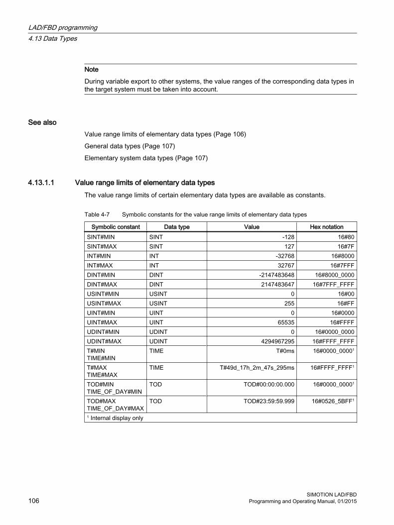
Note
During variable export to other systems, the value ranges of the corresponding data types in the target system must be taken into account.
See alsoValue range limits of elementary data types (Page 106)
General data types (Page 107)
Elementary system data types (Page 107)
4.13.1.1 Value range limits of elementary data typesThe value range limits of certain elementary data types are available as constants.
Table 4-7 Symbolic constants for the value range limits of elementary data types
Symbolic constant Data type Value Hex notationSINT#MIN SINT -128 16#80SINT#MAX SINT 127 16#7FINT#MIN INT -32768 16#8000INT#MAX INT 32767 16#7FFFDINT#MIN DINT -2147483648 16#8000_0000DINT#MAX DINT 2147483647 16#7FFF_FFFFUSINT#MIN USINT 0 16#00USINT#MAX USINT 255 16#FFUINT#MIN UINT 0 16#0000UINT#MAX UINT 65535 16#FFFFUDINT#MIN UDINT 0 16#0000_0000UDINT#MAX UDINT 4294967295 16#FFFF_FFFFT#MINTIME#MIN
TIME T#0ms 16#0000_00001
T#MAXTIME#MAX
TIME T#49d_17h_2m_47s_295ms 16#FFFF_FFFF1
TOD#MINTIME_OF_DAY#MIN
TOD TOD#00:00:00.000 16#0000_00001
TOD#MAXTIME_OF_DAY#MAX
TOD TOD#23:59:59.999 16#0526_5BFF1
1 Internal display only
LAD/FBD programming4.13 Data Types
SIMOTION LAD/FBD106 Programming and Operating Manual, 01/2015

4.13.1.2 General data typesGeneral data types are often used for the input and output parameters of system functions and system function blocks. The subroutine can be called with variables of each data type that is contained in the general data type.
The following table lists the available general data types:
Table 4-8 General data types
General data type Data types containedANY_BIT BOOL, BYTE, WORD, DWORDANY_INT SINT, INT, DINT, USINT, UINT, UDINTANY_REAL REAL, LREALANY_NUM ANY_INT, ANY_REALANY_DATE DATE, TIME_OF_DAY (TOD), DATE_AND_TIME (DT)ANY_ELEMENTARY ANY_BIT, ANY_NUM, ANY_DATE, TIME, STRINGANY ANY_ELEMENTARY, user-defined data types (UDT), system data types,
data types of the technology objects
Note
You cannot use general data types as type identifiers in variable or type declarations.
The general data type is retained when a user-defined data type (UDT) is derived directly from an elementary data type (only possible with the SIMOTION ST programming language).
4.13.1.3 Elementary system data typesIn the SIMOTION system, the data types specified in the table are treated in a similar way to the elementary data types. They are used with many system functions.
Table 4-9 Elementary system data types and their use
Identifier Bit width UseStructAlarmId 32 Data type of the alarmId for the project-wide unique identification of
the messages. The alarmId is used for the message generation.Please refer to the SIMOTION Basic Functions Function Manual.Initialization with STRUCTALARMID#NIL
StructTaskId 32 Data type of the taskId for the project-wide unique identification of the tasks in the execution system.Please refer to the SIMOTION Basic Functions Function Manual.Initialization with STRUCTTASKID#NIL
LAD/FBD programming4.13 Data Types
SIMOTION LAD/FBDProgramming and Operating Manual, 01/2015 107

Table 4-10 Symbolic constants for invalid values of elementary system data types
Symbolic constant Data type MeaningSTRUCTALARMID#NIL StructAlarmId Invalid AlarmIdSTRUCTTASKID#NIL StructTaskId Invalid TaskId
4.13.2 User-defined data types
4.13.2.1 Defining user-defined data types (UDT)You can create user-defined data types in units and programs/charts:
● Structures (Page 108)
● Enumerations (Page 109)
The scope of the data type declaration (Page 108) depends on the location of the declaration.
4.13.2.2 Scope of the data type declarationYou create derived data types in the declaration tables of the source file or the program/chart. The scope of the data type declaration depends on the location of the declaration.
● In the declaration table of the unit, Interface (exported declaration) section:The data type is valid for the entire source file; all programs/charts (programs, function blocks, and functions) within the source file can access the data type.These variables are also available, if appropriately connected (see Define connections (Page 163)), in other source files (or other units).
● In the declaration table of the unit, Implementation (unit-internal declaration) section:The data type is valid in the source file; all programs/charts (programs, function blocks, and functions) within the source file can access the data type.
● In the declaration table of the program/chart:The data type can only be accessed within the program/chart in which it is declared.
4.13.2.3 Defining structuresYou define structures in the declaration tables of the unit or the program/chart. The scope (Page 108) of the structures depends on the location of the declaration.
To define structures, proceed as follows:
1. Select the declaration table and, if applicable, the section of the declaration table for the desired scope.
2. Select the Structures tab.
3. Enter the name of the structure.
LAD/FBD programming4.13 Data Types
SIMOTION LAD/FBD108 Programming and Operating Manual, 01/2015
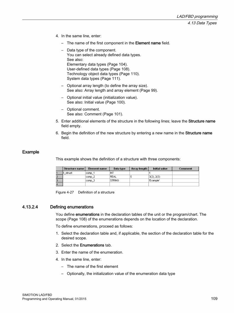
4. In the same line, enter:
– The name of the first component in the Element name field.
– Data type of the component.You can select already defined data types.See also:Elementary data types (Page 104).User-defined data types (Page 108).Technology object data types (Page 110).System data types (Page 111).
– Optional array length (to define the array size).See also: Array length and array element (Page 99).
– Optional initial value (initialization value).See also: Initial value (Page 100).
– Optional comment.See also: Comment (Page 101).
5. Enter additional elements of the structure in the following lines; leave the Structure name field empty.
6. Begin the definition of the new structure by entering a new name in the Structure name field.
Example This example shows the definition of a structure with three components:
Figure 4-27 Definition of a structure
4.13.2.4 Defining enumerationsYou define enumerations in the declaration tables of the unit or the program/chart. The scope (Page 108) of the enumerations depends on the location of the declaration.
To define enumerations, proceed as follows:
1. Select the declaration table and, if applicable, the section of the declaration table for the desired scope.
2. Select the Enumerations tab.
3. Enter the name of the enumeration.
4. In the same line, enter:
– The name of the first element
– Optionally, the initialization value of the enumeration data type
LAD/FBD programming4.13 Data Types
SIMOTION LAD/FBDProgramming and Operating Manual, 01/2015 109

5. Enter additional elements of the enumeration in the following lines; leave the Enumeration name field empty.
6. You begin the definition of the new enumeration by entering a new name in the Enumeration name field.
ExampleThis example shows the definition of an enumeration data type with the name Color and the enumeration elements Red, Blue, and Green, as well as the initialization value (initial value) Green.
If no initialization value is entered during the enumeration definition (data type declaration), the first value of the enumeration is assigned to the data type. In this example, this means Red would be used for the initialization because it is defined as the first enumeration element.
Figure 4-28 Definition of an enumeration data type
4.13.3 Technology object data types
4.13.3.1 Description of the technology object data typesYou can declare variables with the data type of a technology object (TO). The following table shows the data types for the available technology objects in the individual technology packages.
For example, you can declare a variable with the data type posaxis and assign it an appropriate instance of a position axis. Such a variable is often referred to as a reference.
Table 4-11 Data types of technology objects (TO data type)
Technology object Data type Contained in the technology pack‐age
Drive axis DriveAxis CAM, PATH1, CAM_EXTExternal encoder ExternalEncoderType CAM, PATH1, CAM_EXTMeasuring input MeasuringInputType CAM, PATH1, CAM_EXTOutput cam OutputCamType CAM, PATH1, CAM_EXTCam track _CamTrackType CAM, PATH1, CAM_EXTPosition axis PosAxis CAM, PATH1, CAM_EXTFollowing axis FollowingAxis CAM, PATH1, CAM_EXTFollowing object FollowingObjectType CAM, PATH1, CAM_EXT
LAD/FBD programming4.13 Data Types
SIMOTION LAD/FBD110 Programming and Operating Manual, 01/2015

Technology object Data type Contained in the technology pack‐age
Cam CamType CAM, PATH1, CAM_EXTPath axis1 _PathAxis PATH1, CAM_EXTPath object1 _PathObjectType PATH1, CAM_EXTFixed gear _FixedGearType CAM_EXTAddition object _AdditionObjectType CAM_EXTFormula object _FormulaObjectType CAM_EXTSensor _SensorType CAM_EXTController object _ControllerObjectType CAM_EXTTemperature channel TemperatureControllerType TControlGeneral data type,to which every TO can be as‐signed
ANYOBJECT
1 Available as of version V4.1.
You can access the elements of technology objects (configuration data and system variables) via structures (see SIMOTION Basic Functions Function Manual).
Table 4-12 Symbolic constants for invalid values of technology object data types
Symbolic constant Data type MeaningTO#NIL ANYOBJECT Invalid technology object
See alsoInheritance of the properties for axes (Page 111)
4.13.3.2 Inheritance of the properties for axesInheritance for axes means that all of the data types, system variables and functions of the TO driveAxis are fully included in the TO positionAxis. Similarly, the position axis is fully included in the TO synchronizedAxis, the following axis in the TO pathAxis. This has, for example, the following effects:
● If a function or a function block expects an input parameter of the driveAxis data type, you can also use a position axis or a synchronized axis or a path axis when calling.
● If a function or a function block expects an input parameter of the posAxis data type, you can also use a synchronized axis or a path axis when calling.
4.13.4 System data typesThere are a number of system data types available that you can use without a previous declaration. And, each imported technology packages provides a library of system data types.
LAD/FBD programming4.13 Data Types
SIMOTION LAD/FBDProgramming and Operating Manual, 01/2015 111

Additional system data types (primarily enumeration and STRUCT data types) can be found
● In parameters for the general standard functions (see SIMOTION Basic Functions Function Manual)
● In parameters for the general standard function blocks (see SIMOTION Basic Functions Function Manual)
● In system variables of the SIMOTION devices (see relevant parameter manuals)
● In parameters for the system functions of the SIMOTION devices (see relevant parameter manuals)
● In system variables and configuration data of the technology objects (see relevant parameter manuals)
● In parameters for the system functions of the technology objects (see relevant parameter manuals)
LAD/FBD programming4.13 Data Types
SIMOTION LAD/FBD112 Programming and Operating Manual, 01/2015

4.14 VariablesVariables are an important component of programming and provide structure to programs. They are placeholders which can be assigned values that can be accessed several times in the program.
Variables have:
● A specific initialization behavior and scope of validity
● A data type and operations which are defined for that data type
User and system variables are differentiated. User variables can be defined by the user. System variables are provided by the system.
4.14.1 Keywords for variable typesThe various keywords for variable types are shown in the following table.
Description of keywords for variable types
Keyword Description UseGlobal user variables (declared in the interface or implementation section of the unit1)VAR_GLOBAL Unit variable; can be accessed by all POUs within the source file.
If the variable was declared in the interface section, it can be used in another source file once a connection has been defined in its declaration table (see Define connections (Page 163)).
FB, FC, program
VAR_GLOBAL RETAIN Retentive unit variable; retained during power outage. FB, FC, programVAR_GLOBAL CONSTANT Unit constant; cannot be changed from the program. FB, FC, programLocal user variables (declared within a POU2)VAR Local variable (static for FB and program, temporary for FC) FB, FC, programVAR_TEMP Temporary local variable FB, programVAR_INPUT Input parameters: Local variable; value is supplied from external source
and can only be read in the FB or FC.FB, FC
VAR_OUTPUT Output parameters: Local variable; value is sent to an external destination by the FB. It can be read as an instance variable after being called by the FB (FB instance name.variable name).
FB
VAR_IN_OUT In/out parameter; the FB or FC accesses this variable directly (by means of a reference) and can change it directly.
FB, FC
VAR CONSTANT Local constant; cannot be changed from the program. FB, FC, program1 MCC and LAD/FBD programming languages: in the declaration table of the respective source file.2 MCC and LAD/FBD programming languages: in the declaration table of the respective chart/program.
LAD/FBD programming4.14 Variables
SIMOTION LAD/FBDProgramming and Operating Manual, 01/2015 113

4.14.2 Defining variables
Variables are defined in the symbol browser or in the declaration table of the source file or chart/program. The following table provides an overview of where the relevant variable is defined.
Definition of variables
Variable type Defined in...Global device user var‐iables
Symbol browser
unit variable Declaration table of the source file as VAR_GLOBAL, VAR_GLOBAL RETAIN or VAR_GLOBAL CONSTANT
Local variable Declaration table of the program/chart as:● VAR, VAR_TEMP, or VAR CONSTANT● Additionally for function blocks as VAR_INPUT, VAR_OUTPUT,
VAR_IN_OUT● Additionally for functions as VAR_INPUT, VAR_IN_OUT
I/O variable Symbol browserSymbolic access to the fixed process image of the BackgroundTask
● Declaration table of the source file● Declaration table of the program/chart (programs and FB only)
4.14.2.1 Use of global device variablesGlobal device variables are user-defined variables that you can access from all program sources (e.g. ST source files, MCC source files) of a SIMOTION device.
Global device variables are created in the symbol browser tab of the detail view; to do this, you must be working in offline mode.
Here is a brief overview of the procedure:
1. In the project navigator of SIMOTION SCOUT, select the GLOBAL DEVICE VARIABLES element in the SIMOTION device subtree.
2. In the detail view, select the Symbol browser tab and scroll down to the end of the variable table (empty row).
3. In the last (empty) row of the table, enter or select the following:
– Name of variable
– Data type of variable (only elementary data types are permitted)
4. Optionally, you can make the following entries:
– Activation of Retain checkbox (This declares the variable as retentive, so that its value will be retained after a power failure.)
– Field length (array size)
– Initial value (if array, for each element)
– Display format (if array, for each element)
LAD/FBD programming4.14 Variables
SIMOTION LAD/FBD114 Programming and Operating Manual, 01/2015

You can now access this variable using the symbol browser or any program of the SIMOTION device.
In ST source files, you can use a global device variable, just like any other variable.
Note
If you have declared unit variables or local variables of the same name (e.g. var-name), specify the global device variable with _device.var-name.
An alternative to global device variables is the declaration of unit variables in a separate unit, which is imported into other units. This has the following advantages:1. Variable structures can be used.2. The initialization of the variables during the STOP-RUN transition is possible (via Program
in StartupTask).3. For newly created global unit variables, a download in RUN is also possible.
Please refer to the SIMOTION Basic Functions Function Manual.
4.14.2.2 Declaring a unit variable in the source fileThe unit variable is declared in the unit. The scope of validity of the variable is dependent on the section of the declaration table in which the variable is declared:
● In the interface section of the declaration table (INTERFACE):The unit variable is valid for the entire unit; all programs/charts (programs, function blocks, and functions) within the unit can access the unit variable. It is exported and can be used in other source files or units (e.g. ST source files, MCC units, LAD/FBD units) after a connection has been defined (Page 163). It is also available on HMI devices as standard. The total size of the unit variables that can be exported to HMI devices is limited to 64 KB per unit.
● In the implementation section of the declaration table (IMPLEMENTATION):The unit variable is valid in the unit only; all programs/charts (programs, function blocks, and functions) within the unit can access the unit variable.
If you insert pragma lines (Page 121) into the declaration table, you can split the unit variables into data blocks with a separate version code (Page 132). You can also use the pragma lines to define a separate initialization behavior (Page 126) for each of these data blocks and change the defaults for HMI export (Page 134).
LAD/FBD programming4.14 Variables
SIMOTION LAD/FBDProgramming and Operating Manual, 01/2015 115

Proceed as follows; the unit (declaration table) is open, see Open existing program source (Page 51):
1. In the declaration table, select the section for the desired scope.
2. Then select the Parameters tab.
3. Enter:
– Name of the variable.
– Variable type.See also: Keywords for variable types (Page 113).
– Data type of the variables.You can select already defined data types.See also: Data types (Page 104).
– Optional array length (to define the array size).See also: Array length and array element (Page 99).
– Optional initial value (initialization value).See also: Initial value (Page 100).
– Optional comment.See also: Comment (Page 101).
The variable is then declared and can be used immediately within the unit.
Note
Outside the unit (e.g. in the symbol browser), the variable is only available after the unit has been compiled.
Figure 4-29 Example: Declaring a unit variable in the unit
LAD/FBD programming4.14 Variables
SIMOTION LAD/FBD116 Programming and Operating Manual, 01/2015

Note
The declaration table of the unit is read each time parameters are assigned for a command. Inconsistent data within the declaration table may, therefore, cause unexpected error messages during parameter assignment.
4.14.2.3 Declaring local variablesA local variable can only be accessed within the program/chart (program, function, function block) in which it is declared.
We distinguish between the following:
● Static variables:Static variables retain their value over all passes of the unit section (block memory).
● Temporary variables:Temporary variables are initialized each time the unit section is called again.
See also: Initialization of local variables (Page 128).
If you insert a pragma line (Page 121) at the start of the declaration table, you can influence the initialization of static variables of programs (Page 129).
Proceed as follows; the program/chart with the declaration table is open (see Open existing program source (Page 51)):
1. In the declaration table, select the Parameters/Variables tab.
2. Enter:
– Name of the variable.
– Variable type for variables.See also: Keywords for variable types (Page 113).
– Data type of the variables.You can select already defined data types.See also: Data types (Page 104).
– Optional array length (to define the array size).See also: Array length and array element (Page 99).
– Optional initial value (initialization value).See also: Initial value (Page 100).
– Optional comment.See also: Comment (Page 101).
The variable is now declared and can be used immediately.
Figure 4-30 Example: Declaring a local variable in the chart/program
LAD/FBD programming4.14 Variables
SIMOTION LAD/FBDProgramming and Operating Manual, 01/2015 117

Note
The declaration table of the program/chart is read each time parameters are assigned for a command. Inconsistent data within the declaration table may, therefore, cause unexpected error messages during parameter assignment.
4.14.2.4 Defining variables in the Variable declaration dialog box ("on-the-fly" variable declaration)As soon as you enter an unknown variable in the parameter screen form for an MCC command or an LAD/FBD graphic, the Variable declaration dialog box appears.
Figure 4-31 Variable declaration dialog box
Note
In order for the Variable declaration dialog box to appear, the on-the-fly variable declaration checkbox must be activated in the Settings dialog box.
LAD/FBD programming4.14 Variables
SIMOTION LAD/FBD118 Programming and Operating Manual, 01/2015

ProcedureTo define variables "on-the-fly" in the Variable declaration dialog box, proceed as follows:
1. Enter only the name of the variables in an input field of the parameter screen for an MCC command or LAD/FBD graphic and press the Return key.If the entered identifier is not a valid variable name, the dialog box Variable declaration appears.
2. Enter:
– Another variable name, if required.
– The Data type of the variablesAvailable for selection are all elementary data types (Page 104) and, where appropriate, the data type suitable for the input field.Select the data type or enter the identifier of a data type.
– The variable type.Available for selection are all allowed keywords for variable types (Page 113).Select the variable type.If you select a global variable type (e.g. VAR_GLOBAL), the checkbox Exportable becomes active.
– The Absolute identifier for access to the fixed process image of the background task (Page 150).You can only enter the identifier for the absolute access to the fixed process image of the background task if you have selected a data type that is included in the general data types (Page 107) ANY_BIT or ANY_INT.Enter the absolute identifier according to the Syntax (Page 157).The variable is displayed in the register I/O symbols of the declaration table.
– Optional array length.Here, you specify the size of the array.Not available if an absolute identifier is entered.See also: Array length and array element (Page 99).
– Optional initial value (initialization value).Not available if an absolute identifier is entered.See also: Initial value (Page 100).
– Optional comment.See also: Comment (Page 101).
Figure 4-32 Example: Variable declaration
LAD/FBD programming4.14 Variables
SIMOTION LAD/FBDProgramming and Operating Manual, 01/2015 119

Figure 4-33 Example: Variable declaration (absolute name)
3. Confirm with OK.
ResultThe variable is defined and entered in the declaration table of the source or the MCC chart or the LAD/FBD program, depending on the selected variable type and the Exportable checkbox:
● With local variables (e.g. VAR), the Exportable checkbox has a gray background and the new variable is entered in the declaration table of the MCC chart or the LAD/FBD program.
● With global variables (e.g. VAR_GLOBAL), the Exportable checkbox is shown activated:
– If the Exportable checkbox is activated, the new variable is entered in the implementation section of the unit's declaration table.
– If the Exportable checkbox is not activated, the new variable is entered in the interface section of the unit's declaration table.
Note
If you leave the Variable declaration dialog box by clicking Cancel, your input remains as it is, and the variable is not created.
LAD/FBD programming4.14 Variables
SIMOTION LAD/FBD120 Programming and Operating Manual, 01/2015

4.14.2.5 Pasting pragma lines during variable definitionPragma lines in declaration tables have the following function:
● In declaration tables of units (declaration of unit variables):Pragma lines in the interface section or implementation section of the declaration table split the variables of the respective section into different subsections:
– The 1st subsection begins at the start of the relevant table and finishes at the 1st pragma line.
– All the other subsections start at one pragma line and finish at the next (or at the end of the table if starting at the last pragma line).
Within these subsections of the table, each of the variables declared with VAR_GLOBAL or VAR_GLOBAL RETAIN forms a data block with a separate version code (Page 132). If the version code is changed, only the data block concerned will be initialized during a download.Configure the pragma line in order to change the initialization behavior or the HMI export of the next data block (see following Section Pragmas in the declaration tables of the unit variables).
● In the declaration table of a program/chart (declaration of local variables):Line 1 may only contain one pragma line for changing the initialization behavior of programs' static variables (see the section titled Pragmas in the declaration tables for local variables later in this document).
Note
The SIMOTION Kernel version partially determines the effectiveness of pragma lines. This is specified for individual parameters.
Inserting a pragma lineTo insert a pragma line into the declaration table, proceed as follows:
1. Select the Parameters tab (for unit variables) or Parameters/variables tab (for local variables).
2. In the declaration table, set the cursor to the number of the line at which a new data block is to be started.Only line 1 can be used in the declaration table for local variables.
3. Select the Insert pragma line context menu.A new line containing the Pragmas button only is inserted above the line.
4. Left-click the Pragmas button.A window containing configuration options for the relevant declaration table opens.
5. Enter the settings.
6. Confirm with OK.
LAD/FBD programming4.14 Variables
SIMOTION LAD/FBDProgramming and Operating Manual, 01/2015 121

Pragmas in the declaration tables for unit variablesA pragma line has been inserted into the declaration table for unit variables. If you click the "Pragmas" button in the table, the following window appears:
Figure 4-34 Pragma settings in the declaration table for unit variables (e.g. interface section)
This window is for making the settings below. These influence the data block following the pragma line:
Table 4-13 Parameters for pragma settings in the declaration table for unit variables
Parameter DescriptionInitialization of unit data Initialization of VAR_GLOB‐
AL during STOP‑RUN transi‐tion
Only as of version V4.1 of the SIMOTION Kernel.This setting determines whether the next data block of the non-retentive unit variables is initialized during the transition from STOP to RUN operating state.Setting on the device (standard):● As of version V4.2 of the SIMOTION Kernel: The setting made on the SIMOTION
device applies.● Up to version V4.1 of the SIMOTION Kernel: Variables are not initialized.Always: Variables are initialized.Never: Variables are not initialized.
Initialization of VAR_GLOB‐AL during a change
This setting determines whether a download for the next data block of the non-retentive unit variables can be performed in RUN if the version code has changed.Active: A download in RUN is possible.Inactive (standard): A download in RUN is not possible.
Initialization of VAR_GLOB‐AL RETAIN during a change
This setting determines whether a download for the next data block of the retentive unit variables can be performed in RUN if the version code has changed.Active: A download in RUN is possible.Inactive (standard): A download in RUN is not possible.
HMI data connection
LAD/FBD programming4.14 Variables
SIMOTION LAD/FBD122 Programming and Operating Manual, 01/2015

Parameter Description Use the settings below to change which unit variables are available on which HMI
devices by default.Detailed description of the HMI export, in particular the effect of the settings depending on SIMOTION Kernel version: see Variables and HMI devices (Page 134).
VAR_GLOBAL for HMI devi‐ces
Active (standard in the interface section): The next data block of the non-retentive unit variables is available on HMI devices.Inactive (standard in the interface section):The next data block of the non-retentive unit variables is not available on HMI devices.
VAR_GLOBAL RETAIN for HMI devices
Active (standard in the interface section): The next data block of the retentive unit variables is available on HMI devices.Inactive (standard in the interface section):The next data block of the retentive unit variables is not available on HMI devices.
Pragmas in the declaration tables for local variablesA pragma line has been inserted into line 1 of the declaration table for local variables. If you click the "Pragmas" button in the table, the following window appears:
Figure 4-35 Pragma settings in the declaration table for local variables
You can make the following settings in this window:
Note
These settings only take effect in the following scenarios:1. The "Only create program instance data once" compiler option is active on the higher-level
unit.2. The creation type of the program/chart is "Program".
LAD/FBD programming4.14 Variables
SIMOTION LAD/FBDProgramming and Operating Manual, 01/2015 123

Table 4-14 Parameters for pragma settings in the declaration table for local variables
Parameter DescriptionInitialization of VAR during a change This setting determines whether a download for the next static variables can be per‐
formed in RUN if the version code has changed.Active: A download in RUN is possible.Inactive (standard): A download in RUN is not possible.
Initialization of VAR during STOP‑RUN transition
Only as of version V4.1 of the SIMOTION Kernel.This setting determines whether the next static variables are initialized during the tran‐sition from STOP to RUN operating state.Setting on the device (standard):● As of version V4.2 of the SIMOTION Kernel: The setting made on the SIMOTION
device applies.● Up to version V4.1 of the SIMOTION Kernel: Variables are not initialized.Always: Variables are initialized.Never: Variables are not initialized.
4.14.3 Time of the variable initialization
The timing of the variable initialization is determined by:
● Memory area to which the variable is assigned
● Operator actions (e.g. source file download to the target system)
● Execution behavior of the task (sequential, cyclic) to which the program was assigned.
All variable types and the timing of their variable initialization are shown in the following tables. You will find basic information about tasks in the SIMOTION Basic Functions Function Manual.
The behavior for variable initialization during download can be set: To do this, as a default setting select the Options > Settings menu and the Download tab or define the setting during the current download.
Note
You can upload values of unit variables or global device variables from the SIMOTION device into SIMOTION SCOUT and save them in XML format.1. Save the required data segments of the unit variables or global device variables as a data
set with the function _saveUnitDataSet.2. Use the Save variables function in SIMOTION SCOUT.
You can use the Restore variables function to download these data sets and variables back to the SIMOTION device.
For more information, refer to the SIMOTION SCOUT Configuration Manual.
This makes it possible, for example, to obtain this data, even if it is initialized by a project download or if it becomes unusable (e.g. due to a version change of SIMOTION SCOUT).
LAD/FBD programming4.14 Variables
SIMOTION LAD/FBD124 Programming and Operating Manual, 01/2015
4.14.3.1 Initialization of retentive global variablesRetentive variables retain their last value after a loss of power. All other data is reinitialized when the device is switched on again.
Retentive global variables are initialized:
● When the backup or buffer for retentive data fails.
● When the firmware is updated.
● When a memory reset (MRES) is performed.
● With the restart function (Del. SRAM) in SIMOTION P320 or P350.
● By applying the _resetUnitData function, possible selectively for different data segments of the retentive data.
● When a download is performed according to the following description.
LAD/FBD programming4.14 Variables
SIMOTION LAD/FBDProgramming and Operating Manual, 01/2015 125

Behavior during download
Table 4-15 Initializing retentive global variables during download
Variable type Time of the variable initialization Retentive global de‐vice variables
The behavior during the download depends on the Initialization of retentive program data and re‐tentive global device variables setting1:● Yes2: All retentive global device variables are initialized.● No3: The retentive global device variables are only initialized if their version code is changed.See: Version code of global variables and their initialization during download (Page 132).
Retentive unit variables The behavior during the download depends on the Initialization of retentive program data and re‐tentive global device variables setting1:● Yes2: All retentive unit variables (all units) are initialized.● No3: A data block ( = declaration block)4 of the retentive unit variables in the interface or
implementation section is only initialized5 if its version code is changed.See: Version code of global variables and their initialization during download (Page 132).
1 Default setting in the Options > Settings menu, Download tab,or the current setting for the download.2 The corresponding check box is active.3 The corresponding check box is inactive.4 With the SIMOTION ST programming language:A data block of the retentive unit variables corresponds to a VAR_GLOBAL RETAIN/END_VAR declaration block in the interface section or implementation section.With the SIMOTION MCC and SIMOTION LAD/FBD programming languages:A data block of the retentive unit variables is formed as follows from the variables declared with VAR_GLOBAL RETAIN in the interface section or implementation section of the declaration table: Pragma lines (Page 121) within a section of the declaration table separate the variables into different data blocks.5 Initialization of a changed data block also occurs during a download in RUN, provided the following condition is fulfilled:With the SIMOTION ST programming language: The following attribute has been specified within a pragma in the relevant declaration block: { Block‐Init_OnChange := TRUE; }.With the SIMOTION MCC or SIMOTION LAD/FBD programming languages:A pragma line (Page 121) has been pasted into the declaration table and the following check box is activated: Initialization of VAR_GLOBAL RETAIN during a change. All the variables declared with VAR_GLOBAL RETAIN up to the next pragma line or the end of the table form a data block accordingly.For information on the general conditions for a download in RUN, see the SIMOTION Basic Functions Function Manual.
4.14.3.2 Initialization of non-retentive global variablesNon-retentive global variables lose their value during power outages. They are initialized:
● During the initialization of retentive global variables (Page 125), e.g. during a firmware update or overall reset (MRES).
● During switch-on.
● By applying the _resetUnitData function, possible selectively for different data segments of the non-retentive data.
● During a download as described in the following table.
● During the transition from STOP to RUN mode as described at the end of the section.
LAD/FBD programming4.14 Variables
SIMOTION LAD/FBD126 Programming and Operating Manual, 01/2015

Behavior during download
Table 4-16 Initializing non-retentive global variables during download
Variable type Time of the variable initialization Non-retentive global device variables
The behavior during the download depends on the Initialization of non-retentive program data and non-retentive global device variables setting1:● Yes2: All non-retentive global device variables are initialized.● No3: The non-retentive global device variables are only initialized if their version code is changed.See: Version code of global variables and their initialization during download (Page 132).
Non-retentive unit vari‐ables
The behavior during the download depends on the Initialization of non-retentive program data and non-retentive global device variables setting1:● Yes2: All non-retentive unit variables (all units) are initialized.● No3: A data block ( = declaration block)4 of the non-retentive unit variables in the interface or
implementation section is only initialized5 if its version code is changed.See: Version code of global variables and their initialization during download (Page 132).
1 Default in the Options > Settings menu, Download tab, or the current setting for the download.2 The corresponding check box is active.3 The corresponding check box is inactive.4 With the SIMOTION ST programming language:A data block of the non-retentive unit variables corresponds to a VAR_GLOBAL/END_VAR declaration block in the interface section or implementation section.With the SIMOTION MCC or SIMOTION LAD/FBD programming languages:A data block of the non-retentive unit variables is formed as follows from the variables declared with VAR_GLOBAL in the interface section or implementation section of the declaration table: Pragma lines (Page 121) within a section of the decla‐ration table separate the variables into different data blocks.5 Initialization of a changed data block also occurs during a download in RUN, provided the following condition is fulfilled:With the SIMOTION ST programming language: The following attribute has been specified within a pragma in the relevant declaration block: { Block‐Init_OnChange := TRUE; }.With the SIMOTION MCC or SIMOTION LAD/FBD programming languages:A pragma line (Page 121) has been pasted into the declaration table and the following check box is activated: Initialization of VAR_GLOBAL during a change. All the variables declared with VAR_GLOBAL up to the next pragma line or the end of the table form a data block accordingly.For information on the general conditions for a download in RUN, see SIMOTION Basic Functions Function Manual.
Behavior during STOP-RUN transitionThe values of non-retentive global variables are retained by default during the transition from STOP to RUN mode.
LAD/FBD programming4.14 Variables
SIMOTION LAD/FBDProgramming and Operating Manual, 01/2015 127

You can, however, make a setting whereby the non-retentive global variables are initialized during the STOP-RUN transition:
● As of Version V4.2 of the SIMOTION Kernel, by activating the Initialization of non-retentive global variables and program data during STOP-RUN transition checkbox on the SIMOTION device.With non-retentive unit variables, this setting can be overwritten by a pragma or pragma line (Page 121) in the relevant data blocks of the program sources.
● As of Version V4.1 of the SIMOTION Kernel, by a pragma or pragma line in the relevant data blocks of the program sources (only with non-retentive unit variables):
– With the SIMOTION ST programming language:Specify the following attribute within a pragma in the relevant VAR_GLOBAL/END_VAR declaration block: { BlockInit_OnDeviceRun := ALWAYS; }
– With the SIMOTION MCC or SIMOTION LAD/FBD programming languages:Paste a pragma line (Page 121) with the following setting into the declaration table: "Initialization during STOP-RUN transition = Always". All the variables declared with VAR_GLOBAL up to the next pragma line or the end of the table form a data block which is initialized during the STOP-RUN transition.
Note
With SIMOTION devices up to SIMOTION Kernel Version V4.0, non-retentive global variables are never initialized during the STOP-RUN transition.
4.14.3.3 Initialization of local variablesLocal variables are initialized:
● For the initialization of retentive unit variables (Page 125).
● For the initialization of non-retentive unit variables (Page 126).
● Also, according to the following description:
Table 4-17 Initialization of local variables
Variable type Time of the variable initialization Local program varia‐bles
Local variables of programs are initialized differently:● Static variables (VAR) are initialized according to the memory area in which they are stored.
See: Initialization of static program variables (Page 129).● Temporary variables (VAR_TEMP) are initialized every time the program of the task is called.
Local variables of func‐tion blocks (FB)
Local variables of function blocks are initialized differently:● Static variables (VAR, VAR_IN, VAR_OUT) are only initialized when the FB instance is initialized.
See: Initialization of instances of function blocks (FBs) (Page 130).● Temporary variables (VAR_TEMP) are initialized every time the FB instance is called.
Local variables of func‐tions (FC)
Local variables of functions are temporary and are initialized every time the function is called.
LAD/FBD programming4.14 Variables
SIMOTION LAD/FBD128 Programming and Operating Manual, 01/2015

Note
You can obtain information about the memory requirements of a POU in the local data stack using the Program Structure (Page 194) function.
4.14.3.4 Initialization of static program variablesThe following versions affect the following static variables:
● Local variables of a unit program declared with VAR
● Function block instances declared with VAR within a unit program, including the associated static variables (VAR, VAR_INPUT, VAR_OUTPUT).
LAD/FBD programming4.14 Variables
SIMOTION LAD/FBDProgramming and Operating Manual, 01/2015 129

The initialization behavior is determined by the memory area in which the static variables are stored. This is determined by the "Only create program instance data once" (Page 59) compiler option.
● For the deactivated "Only create program instance data once" compiler option (default):The static variables are stored in the user memory of each task which is assigned to the program.The initialization of the variables thus depends on the execution behavior of the task to which the program is assigned (see SIMOTION Basic Functions Function Manual):
– Sequential tasks (MotionTasks, UserInterruptTasks, SystemInterruptTasks, StartupTask, ShutdownTask): The static variables are initialized every time the task is started.
– Cyclic tasks (BackgroundTask, SynchronousTasks, TimerInterruptTasks): The static variables are only initialized only during the transition from STOP to RUN operating state.
● For the activated "Only create program instance data once" compiler option:This setting is necessary, for example, if a program is to be called within a program.The static variables of all programs from the program source (unit) involved are only stored once in the user memory of the unit.They are thus initialized together with the non-retentive unit variables, see Initialization of non-retentive global variables (Page 126).They are not initialized by default during the transition from STOP to RUN operating state. You can, however, make a setting whereby they are initialized during the STOP-RUN transition:
– As of version V4.2 of the SIMOTION Kernel, by activating the Initialization of non-retentive global variables and program data during STOP-RUN transition checkbox on the SIMOTION device.This setting can be overwritten by a pragma or pragma line (Page 121) in the data block of the relevant program organization unit (POU).
– As of version V4.1 of the SIMOTION Kernel, by a pragma or pragma line in the data block of the relevant program organization unit (POU):With the SIMOTION ST programming language:Specify the following attribute within a pragma in the VAR/END_VAR declaration block: { BlockInit_OnDeviceRun := ALWAYS; }With the SIMOTION MCC or SIMOTION LAD/FBD programming languages:The declaration table starts with a pragma line (Page 121) containing the following setting: "Initialization during STOP-RUN transition = Always". All the variables declared with VAR in the table are initialized during the STOP-RUN transition.
4.14.3.5 Initialization of instances of function blocks (FBs)The initialization of a function block instance (Page 177) is determined by the location of its declaration:
● Global declaration (within VAR_GLOBAL/END_VAR in the interface of implementation section):Initialization as for a non-retentive unit variable, see Initialization of non-retentive global variables (Page 126).
● Local declaration in a program (within VAR / END_VAR):Initialization as for static variables of programs, see Initialization of static variables of programs (Page 129).
LAD/FBD programming4.14 Variables
SIMOTION LAD/FBD130 Programming and Operating Manual, 01/2015

● Local declaration in a function block (within VAR / END_VAR):Initialization as for an instance of this function block.
● Declaration as in/out parameter in a function block or a function (within VAR_IN_OUT / END_VAR):For the initialization of the POU, only the reference (pointer) will be initialized with the instance of the function block remaining unchanged.
Note
You can obtain information about the memory requirements of a POU in the local data stack using the Program Structure (Page 194) function.
4.14.3.6 Initialization of system variables of technology objectsThe system variables of a technology object are usually not retentive. Depending on the technology object, a few system variables are stored in the retentive memory area (e.g. absolute encoder calibration).
The initialization behavior (except in the case of download) is the same as for retentive and non-retentive global variables. See Initialization of retentive global variables (Page 125) and Initialization of non-retentive global variables (Page 126).
The behavior during the download is shown below for:
● Non-retentive system variables
● Retentive system variables
Table 4-18 Initializing technology object system variables during download
Variable type Time of the variable initialization Non-retentive system variables
Behavior during download, depending on the Initialization of all non-retentive data for technology objects setting1:● Yes2: All technology objects are initialized.
– All technology objects are restructured and all non-retentive system variables are initialized.– All technological alarms are cleared.
● No3: Only technology objects changed in SIMOTION SCOUT are initialized.– The technology objects in question are restructured and all non-retentive system variables
are initialized.– All alarms that are pending on the relevant technology objects are cleared.– If an alarm that can only be acknowledged with Power On is pending on a technology object
that will not be initialized, the download is aborted.Retentive system vari‐ables
Only if a technology object was changed in SIMOTION SCOUT, will its retentive system variables be initialized.The retentive system variables of all other technology objects are retained (e.g. absolute encoder calibration).
1 Default in the Options > Settings menu, Download tab, or the current setting for the download.2 The corresponding checkbox is active.3 The corresponding checkbox is inactive.
LAD/FBD programming4.14 Variables
SIMOTION LAD/FBDProgramming and Operating Manual, 01/2015 131

4.14.3.7 Version ID of global variables and their initialization during download
Table 4-19 Version code of global variables and their initialization during download
Data segment Description of version codeGlobal device variables Retentive global de‐
vice variables● Separate version code for each data segment of the global device variables● The version code of the data segment changes for:
– Add or remove a variable within the data segment– Change of the identifier or the data type of a variable within the data segment
● This version code does not change on:– Changes in the other data segment– Changes to initialization values1
● During downloading2, the rule is: This data segment is only initialized when the version code of a data segment is changed.
Non-retentive global device variables
Unit variables of a unit
LAD/FBD programming4.14 Variables
SIMOTION LAD/FBD132 Programming and Operating Manual, 01/2015

Data segment Description of version code Retentive unit varia‐
bles in the interface section
● Several data blocks ( = declaration blocks)3 in each data segment possible.● Own version code for each data block.● The version code of the data block changes for:
– Add or remove a variable in the associated declaration block– Change of variable sequence in the relevant declaration block– Change of the identifier or the data type of a variable in the associated declaration
block– Change of a data type definition (from a separate or imported4 unit) used in the
associated declaration block – Add or remove declaration blocks within the same data segment before the associated
declaration block● This version code does not change on:
– Add or remove declaration blocks in other data segments– Add or remove declaration blocks within the same data segment after the associated
declaration block– Changes in other data blocks– Changes to initialization values1
– Changes to data type definitions that are not used in the associated data block– Changes to functions
● During downloading2, the rule is: This data block is only initialized when the version code of a data block is changed5
● Functions for data backup and initialization take into account the version code of the data blocks.
Retentive unit varia‐bles in the implementa‐tion sectionNon-retentive unit vari‐ables in the interface sectionNon-retentive unit vari‐ables in the implemen‐tation section
1 Changed initialization values are not effective until the data block or data segment in question is initialized.2 If Initialization of retentive program data and retentive global device variables = No and Initialization of non-retentive program data and non-retentive global device variables = No. In the case of other settings: See the sections "Initialization of retentive global variables (Page 125)" and "Initialization of non-retentive global variables (Page 126)".3 With the SIMOTION ST programming language:A data block corresponds to a VAR_GLOBAL/END_VAR or VAR_GLOBAL RETAIN/END_VAR declaration block in the interface section or implementation section.With the SIMOTION MCC or SIMOTION LAD/FBD programming languages:A data block of the non-retentive unit variables is formed as follows from the variables declared with VAR_GLOBAL or VAR_GLOBAL RETAIN in the interface section or implementation section of the declaration table: Pragma lines (Page 121) within a section of the declaration table separate the variables into different data blocks.4 The import of units depends on the programming language, refer to the associated section (Page 163).5 Initialization of a changed data block also occurs during a download in RUN, provided the following condition is fulfilled:With the SIMOTION ST programming language: The following attribute has been specified within a pragma in the relevant declaration block: { Block‐Init_OnChange := TRUE; }.With the SIMOTION MCC or SIMOTION LAD/FBD programming languages:A pragma line (Page 121) has been pasted into the declaration table and the following check box is activated: Initialization of VAR_GLOBAL during a change. All the variables declared with VAR_GLOBAL up to the next pragma line or the end of the table form a data block accordingly.For information on the general conditions for a download in RUN, see SIMOTION Basic Functions Function Manual.
LAD/FBD programming4.14 Variables
SIMOTION LAD/FBDProgramming and Operating Manual, 01/2015 133

4.14.4 Variables and HMI devicesThe following variables are exported to HMI devices where they are available:
● System variables of the SIMOTION device
● System variables of technology objects
● I/O variables
● Global device variables
● Retentive and non-retentive unit variables of the interface section (default setting).Change this default as follows:
– In the SIMOTION ST programming language:For each declaration block with the following pragma: { HMI_Export := FALSE; }.See also Controlling compiler with attributes.
– In the SIMOTION MCC and SIMOTION LAD/FBD programming languages:For the variable declarations following a pragma line (Page 121), if you deactivate the VAR_GLOBAL for HMI devices or VAR_GLOBAL RETAIN for HMI devices parameters in this pragma line.
The unit variables of this kind of data block are not exported to HMI devices. The HMI consistency check is also omitted for them during the download.
The following variables are not exported to HMI devices and are not available there:
● Retentive and non-retentive unit variables of the implementation section (default setting).Change this default as follows:
– In the SIMOTION ST programming language:For each declaration block with the following pragma: { HMI_Export := TRUE; }See also Controlling compiler with attributes.
– In the SIMOTION MCC and SIMOTION LAD/FBD programming languages:For the variable declarations following a pragma line (Page 121), if you activate the VAR_GLOBAL for HMI devices or VAR_GLOBAL RETAIN for HMI devices parameters in this pragma line.
The unit variables of this kind of data block are exported to HMI devices. Consequently, they are subject to the HMI consistency check during the download.
● Local variables of a POU
LAD/FBD programming4.14 Variables
SIMOTION LAD/FBD134 Programming and Operating Manual, 01/2015

Note
The total size of the unit variables that can be exported to HMI devices is limited to 64 KB per unit.
The effect of the { HMI_Export := FALSE; } /{ HMI_Export := TRUE; } pragma (or the VAR_GLOBAL for HMI devices or VAR_GLOBAL RETAIN for HMI devices settings in a pragma line) depends on the SIMOTION Kernel version:● As of Version V4.1 of the SIMOTION Kernel:
The pragma affects the export of the corresponding declaration block to HMI devices and the structure of the HMI address space:– Only those variables in declaration blocks exported to HMI devices occupy the HMI
address space.– Within the HMI address space, the variables are arranged according to order of their
declaration.● Up to Version V4.0 of the SIMOTION Kernel:
The pragma affects only the export of the corresponding declaration block to HMI devices.The HMI address space is also occupied by unit variables of the interface section whose declaration blocks are not assigned to HMI devices.Within the HMI address space, the variables are sorted in the following order:– Retentive unit variables of the interface section (exported and not exported).– Retentive unit variables of the implementation section (only exported).– Non-retentive unit variables of the interface section (exported and not exported).– Non-retentive unit variables of the implementation section (only exported).Within these segments, the variables are arranged according to order of their declaration.
LAD/FBD programming4.14 Variables
SIMOTION LAD/FBDProgramming and Operating Manual, 01/2015 135

Example for the SIMOTION ST programming language
Table 4-20 Example for the control of the HMI export with the corresponding pragma
INTERFACE VAR_GLOBAL // HMI export x1 : DINT; END_VAR VAR_GLOBAL { HMI_Export := FALSE; } // No HMI export x2 : DINT; END_VAR // ...END_INTERFACE IMPLEMENTATION VAR_GLOBAL // No HMI export y1 : DINT; END_VAR VAR_GLOBAL { HMI_Export := TRUE; } // HMI export y2 : DINT; END_VAR // ...END_IMPLEMENTATION
LAD/FBD programming4.14 Variables
SIMOTION LAD/FBD136 Programming and Operating Manual, 01/2015

4.15 Access to inputs and outputs (process image, I/O variables)
4.15.1 Overview of access to inputs and outputsSIMOTION provides several possibilities to access the device inputs and outputs of the SIMOTION device as well as the central and distributed I/O:
● Via direct access with I/O variables Direct access is used to access the corresponding I/O address directly.Define an I/O variable (name and I/O address) without assigning a task to it. The entire address space of the SIMOTION device can be used.It is preferable to use direct access with sequential programming (in MotionTasks); access to current input and output values at a particular point in time is especially important in this case. Further information: Direct access and process image of the cyclic tasks (Page 141).
● Via the process image of cyclic tasks using I/O variables The process image of the cyclic tasks is a memory area in the RAM of the SIMOTION device, on which the whole I/O address space of the SIMOTION device is mirrored. The mirror image of each I/O address is assigned to a cyclic task and is updated using this task. The task remains consistent throughout the whole cycle. This process image is used preferentially when programming the assigned task (cyclic programming).Define an I/O variable (name and I/O address) and assign a task to it. The entire address range of the SIMOTION device can be used.Direct access to this I/O variable is still possible: Specify direct access with _direct.var-name. Further information: Direct access and process image of the cyclic tasks (Page 141).
● Using the fixed process image of the BackgroundTask The process image of the BackgroundTask is a memory area in the RAM of the SIMOTION device, on which a subset of the I/O address space of the SIMOTION device is mirrored. The mirror image is refreshed with the BackgroundTask and is consistent throughout the entire cycle. This process image is used preferentially when programming the BackgroundTask (cyclic programming).The address space 0 .. 63 can be used. I/O addresses that are accessed using the process image of the cyclic task are excluded.Further information: Access to the fixed process image of the BackgroundTask (Page 150).
A comparison of the most important properties is contained in "Important properties of direct access and process image" (Page 138).
You can use I/O variables like any other variable, see "Access I/O variables" (Page 160).
Note
An access via the process image is more efficient than direct access.
LAD/FBD programming4.15 Access to inputs and outputs (process image, I/O variables)
SIMOTION LAD/FBDProgramming and Operating Manual, 01/2015 137

4.15.2 Important features of direct access and process image access
Table 4-21 Important properties of direct access and process image access
Direct access Access to process image of cy‐clic tasks
Access to fixed process image of the BackgroundTask
Permissible address range
Entire address range of the SIMOTION deviceException: I/O variables comprising more than one byte must not contain addresses 63 and 64 contiguously (example: PIW63 or PQD62 are not permitted).
Addresses 0 .. 63.Exception:Up to version V4.1 of the SI‐MOTION Kernel or the "Sepa‐rate process image" setting, addresses used for the proc‐ess image of the cyclic tasks are not permitted.
Address configuration Necessary. The addresses used must be present in the I/O and appropriately configured.The "Rules for I/O addresses for direct access and the process image of the cyclic tasks" (Page 144) must be observed.
Not necessary. Addresses that are not present in the I/O or have not been configured can also be used.
Assigned task None. Cyclic task for selection:● SynchronousTasks,● TimerInterruptTasks,● BackgroundTask.
BackgroundTask.
Memory area for proc‐ess images
- Depends on the SIMOTON Kernel version:● Up to version V4.1:
Separate memory areas in all cases● As of version V4.2:
Option to select a common memory area
LAD/FBD programming4.15 Access to inputs and outputs (process image, I/O variables)
SIMOTION LAD/FBD138 Programming and Operating Manual, 01/2015

Direct access Access to process image of cy‐clic tasks
Access to fixed process image of the BackgroundTask
Update ● Onboard I/O of SIMOTION devices C230-2, C240, and C240 PN:Update occurs in a cycle clock of 125 µs.
● I/O via isochronous PROFIBUS DP, PROFINET and DRIVE-CLiQ as well as Onboard I/O of SIMOTION D devices:The update is performed in the position control cycle clock1.
● I/O via isochronous PROFIBUS DP and PROFINET as well as I/O bus:Update occurs in the interpolator cycle clock1.
Inputs are read at the start of the cycle clock.Outputs are written at the end of the cycle clock.
Update occurs with the as‐signed task:● Inputs are read before the
assigned task is started and transferred to the process input image.
● Process output image is written to the outputs after the assigned task has been completed.
An update is made with the BackgroundTask:● Inputs are read before the
BackgroundTask is started and is transferred to the process input image.
● Process output image is written to the outputs when the BackgroundTask is complete.
Consistency – During the entire cycle of the as‐signed task.Exception: Direct access to out‐put occurs.
During the entire cycle of the BackgroundTask.Exception: Direct access to output occurs.
Consistency is only ensured for elementary data types.When using arrays, the user is responsible for ensuring data con‐sistency.
Use Preferred in MotionTasks Preferred in the assigned task Preferred in the Background‐Task
Declaration as variable Necessary, for the entire device as an I/O variable in the symbol browser.Each byte of the address range may only be assigned to a single I/O variable.Syntax of I/O address: e.g. PIW1022, PQ63.3.
Possible, but not necessary:● For the entire device as I/O
variable in the symbol browser
● As unit variable● As local static variable in a
programDownload of new or changed I/O variables
Only possible in STOP mode. -
Use the absolute ad‐dress
Not supported. Possible, with the following syntax: E.g. %IW62, %Q63.3.
LAD/FBD programming4.15 Access to inputs and outputs (process image, I/O variables)
SIMOTION LAD/FBDProgramming and Operating Manual, 01/2015 139
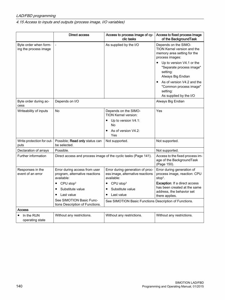
Direct access Access to process image of cy‐clic tasks
Access to fixed process image of the BackgroundTask
Byte order when form‐ing the process image
- As supplied by the I/O Depends on the SIMO‐TION Kernel version and the memory area setting for the process images:● Up to version V4.1 or the
"Separate process image" setting:Always Big Endian
● As of version V4.2 and the "Common process image" setting:As supplied by the I/O
Byte order during ac‐cess
Depends on I/O Always Big Endian
Writeability of inputs No Depends on the SIMO‐TION Kernel version:● Up to version V4.1:
No● As of version V4.2:
Yes
Yes
Write protection for out‐puts
Possible; Read only status can be selected.
Not supported. Not supported.
Declaration of arrays Possible. Not supported.Further information Direct access and process image of the cyclic tasks (Page 141). Access to the fixed process im‐
age of the BackgroundTask (Page 150).
Responses in the event of an error
Error during access from user program, alternative reactions available:● CPU stop2
● Substitute value● Last valueSee SIMOTION Basic Func‐tions Description of Functions.
Error during generation of proc‐ess image, alternative reactions available:● CPU stop3
● Substitute value● Last value
Error during generation of process image, reaction: CPU stop3.Exception: If a direct access has been created at the same address, the behavior set there applies.
See SIMOTION Basic Functions Description of Functions.
Access● In the RUN
operating stateWithout any restrictions. Without any restrictions. Without any restrictions.
LAD/FBD programming4.15 Access to inputs and outputs (process image, I/O variables)
SIMOTION LAD/FBD140 Programming and Operating Manual, 01/2015

Direct access Access to process image of cy‐clic tasks
Access to fixed process image of the BackgroundTask
● During the StartupTask
Possible with restrictions:● Inputs can be read.● Outputs are not written until
StartupTask is complete.
Possible with restrictions:● Inputs are read at the start
of the StartupTask.● Outputs are not written until
StartupTask is complete.
Possible with restrictions:● Inputs are read at the start
of the StartupTask.● Outputs are not written
until StartupTask is complete.
● During the ShutdownTask
Without any restrictions. Possible with restrictions:● Inputs retain status of last
update● Outputs are no longer
written.
Possible with restrictions:● Inputs retain status of last
update● Outputs are no longer
written.
1 The following SIMOTION devices are updated in the Servo_fast cycle or IPO_fast cycle, if the cycles are configured: D445‑2 DP/PN, D455‑2 DP/PN (as of version V4.2) and D435‑2 DP/PN (as of version V4.3).
2 Call the ExecutionFaultTask.3 Call the PeripheralFaultTask.
4.15.3 Direct access and process image of cyclic tasks
PropertyDirect access to inputs and outputs and access to the process image of the cyclic task always take place via I/O variables. The entire address range of the SIMOTION device (Page 143) can be used.
A comparison of the most important properties, also in comparison to the fixed process image of the BackgroundTask (Page 150) is contained in "Important properties of direct access and process image (Page 138)".
Note
Observe the rules for I/O addresses for direct access and the process image of the cyclical tasks (Page 144).
It is particularly important that every address used in an I/O variable is available in the I/O and configured; each byte in the address range may be assigned to no more than one I/O variable (does not apply to access with data type BOOL).
A detailed status of I/O variables (Page 148) can be read as of version V4.2 of the SIMOTION Kernel, for example, in order to check the availability of the I/O variables.
Direct accessDirect access is used to access the corresponding I/O address directly. Direct access is used primarily for sequential programming (in MotionTasks). The access to the current value of the inputs and outputs at a specific time is particularly important.
LAD/FBD programming4.15 Access to inputs and outputs (process image, I/O variables)
SIMOTION LAD/FBDProgramming and Operating Manual, 01/2015 141

For direct access, you define an I/O variable (Page 145) without assigning it a task.
Process image of the cyclic taskThe process image of the cyclic tasks is a memory area in the RAM of the SIMOTION device, on which the whole I/O address space of the SIMOTION device is mirrored. The mirror image of each I/O address is assigned to a cyclic task and is updated using this task. The task remains consistent throughout the whole cycle. This process image is used preferentially when programming the assigned task (cyclic programming). The consistency during the complete cycle of the task is particularly important.
For the process image of the cyclical task you define an I/O variable (Page 145) and assign it a task.
Direct access to this I/O variable is still possible: Specify direct access with _direct.var-name.
Note
An access via the process image is more efficient than direct access.
Additional properties as of version V4.2 of the SIMOTION KernelAs of version V4.2 of the SIMOTION Kernel, direct access to inputs/outputs and the process image of the cyclic tasks offers additional properties:
● As far as the process image of the cyclic tasks is concerned, a common memory area with the fixed process image of the BackgroundTask can be set (standard with newly created devices)
● As far as the process image of the cyclic tasks is concerned, I/O variables for inputs can be written to (i.e. they can be assigned values).
● A detailed status of I/O variables (Page 148) can be read, for example, in order to check the availability of the I/O variables.
Memory area with the fixed process image of the BackgroundTask● As of version V4.2 of the SIMOTION Kernel, selecting a "Common process image" setting
on the device ensures the memory area for the fixed process image of the BackgroundTask is a subset of the memory area for the process image of the cyclic tasks.
● Up to version V4.1 of the SIMOTION Kernel or the "Separate process image" setting on the device (as of version V4.2 of the SIMOTION Kernel), the fixed process image of the BackgroundTask and the process image of the cyclic tasks occupy different memory areas.
Note
If (and only if) you are also using the fixed process image of the BackgroundTask, it is important to consider the effects of the "Common process image" or "Separate process image" settings on the fixed process image of the BackgroundTask (Page 150).
LAD/FBD programming4.15 Access to inputs and outputs (process image, I/O variables)
SIMOTION LAD/FBD142 Programming and Operating Manual, 01/2015

Table 4-22 Effect of "Common process image" or "Separate process image" settings on the process image of the cyclic tasks
Common process image Separate process imageAvailability Only available as of version V4.2 of the
SIMOTION Kernel:● Setting available for selection● Standard for newly created devices
Up to version V4.1 of the SIMO‐TION Kernel applies:● System characteristic, not
configurable.The following applies as of version V4.2 of the SIMOTION Kernel:● Setting available for selection● Standard with device upgrades
Download of new or changed I/O varia‐bles
Only possible in STOP mode. Only possible in STOP mode.
Byte order when forming the process image and during access
Depends on connected I/O
Effects on the fixed process image of the BackgroundTask
See the relevant table in "Access to the fixed process image of the Background‐Task" (Page 150).
Further information Common process image (Page 152) Separate process image (Page 154)
4.15.3.1 Address range of the SIMOTION devicesThe address range of the SIMOTION devices is specified in the following table according to the version of the SIMOTION Kernel concerned. The complete address range can be used for direct access and process image of the cyclical tasks.
Table 4-23 Address range of the SIMOTION devices according to the version of the SIMOTION Kernel
SIMOTION device
Address range for SIMOTION Kernel versionV3.2 V4.0 V4.1 4.2 V4.3 V4.4
C230‑2 0 .. 2047 3 0 .. 2047 3 0 .. 2047 3 – – -C240 – 0 .. 4095 3 0 .. 4095 3 0 .. 4095 3 0 .. 4095 3 0 .. 4095 3
C240 PN 1 – – 0 .. 4095 4 0 .. 4095 4 0 .. 4095 4 0 .. 4095 4
D410 DP – – 0 .. 8191 3 0 .. 8191 3 0 .. 8191 3 –D410 PN – – 0 .. 8191 4 0 .. 8191 4 0 .. 8191 4 –D410‑2 – – – – 0 .. 8191 3 4 0 .. 8191 3 4
D425 0 .. 4095 3 0 .. 16383 3 4 0 .. 16383 3 4 0 .. 16383 3 4 0 .. 16383 3 4 –D425‑2 – – – – 0 .. 16383 3 4 0 .. 16383 3 4
D435 0 .. 4095 3 0 .. 16383 3 4 0 .. 16383 3 4 0 .. 16383 3 4 0 .. 16383 3 4 –D435‑2 – – – – 0 .. 16383 3 4 0 .. 16383 3 4
D445 0 .. 4095 3 0 .. 16383 3 4 0 .. 16383 3 4 0 .. 16383 3 4 – –D445‑1 1 – – 0 .. 16383 3 4 0 .. 16383 3 4 0 .. 16383 3 4 –D445‑2 – – – 0 .. 16383 3 4 0 .. 16383 3 4 0 .. 16383 3 4
D455‑2 – – – 0 .. 16383 3 4 0 .. 16383 3 4 0 .. 16383 3 4
LAD/FBD programming4.15 Access to inputs and outputs (process image, I/O variables)
SIMOTION LAD/FBDProgramming and Operating Manual, 01/2015 143

SIMOTION device
Address range for SIMOTION Kernel versionV3.2 V4.0 V4.1 4.2 V4.3 V4.4
P320 2 – – 0 .. 4095 4 0 .. 4095 4 0 .. 4095 4 0 .. 4095 4
P350 0 .. 2047 3 0 .. 4095 3 0 .. 4095 3 4 0 .. 4095 3 4 0 .. 4095 3 4 0 .. 4095 3 4
1 Available as of V4.1 SP2 HF42 Available as of V4.1 SP53 For distributed I/O (over PROFIBUS DP), the transmission volume is restricted to 1024 bytes per PROFIBUS DP line.4 For distributed I/O (over PROFINET), the transmission volume is restricted to 4,096 bytes per PROFINET segment.
4.15.3.2 Rules for I/O addresses for direct access and the process image of the cyclical tasks
Note
You must observe the following rules for the I/O variable addresses for direct access and the process image of the cyclic task (Page 141). Compliance with the rules is checked during the consistency check of the SIMOTION project (e.g. during the download). 1. Addresses used for I/O variables must be present in the I/O and configured appropriately
in the HW Config.2. I/O variables comprising more than one byte must not contain addresses 63 and 64
contiguously. The following I/O addresses are not permitted: – Inputs: PIW63, PID61, PID62, PID63– Outputs: PQW63, PQD61, PQD62, PQD63
3. All addresses of an I/O variable comprising more than one byte (e.g. WORD, ARRAY data type) must be within a continuous address range configured in HW Config, e.g. within the address range (slot or subslot) of one I/O module.
4. An I/O address (input or output) can only be used by a single I/O variable of data type BYTE, WORD or DWORD or an array of these data types. Access to individual bits with I/O variables of data type BOOL is possible.
5. If several processes (e.g. I/O variable, technology object, PROFIdrive telegram) access an I/O address, the following applies:– Only a single process can have write access to an I/O address of an output (BYTE,
WORD or DWORD data type).Read access to an output with an I/O variable that is used by another process for write access, is possible.
– All processes must use the same data type (BYTE, WORD, DWORD or ARRAY of these data types) to access this I/O address. Access to individual bits is possible irrespective of this.Please be aware of the following, for example, if you wish to use an I/O variable to read the PROFIdrive telegram transferred to or from the drive: The length of the I/O variable must match the length of the telegram.
– Write access to different bits of an address is possible from several processes; however, write access with the data types BYTE, WORD or DWORD is then not possible.
LAD/FBD programming4.15 Access to inputs and outputs (process image, I/O variables)
SIMOTION LAD/FBD144 Programming and Operating Manual, 01/2015

Note
These rules do not apply to accesses to the fixed process image of the BackgroundTask (Page 150). These accesses are not taken into account during the consistency check of the project (e.g. during download).
4.15.3.3 Creating I/O variables for direct access or process image of cyclic tasksCreate I/O variables for direct access or a process image of the cyclic tasks in the address list of the detail view.
This is only possible in offline mode.
Here is a brief overview of the procedure:
1. Select the "Address list" tab in the detail view and choose the SIMOTION deviceorIn the project navigator of SIMOTION SCOUT, double-click the "ADDRESS LIST" element in the SIMOTION device subtree.
2. Select the line before which you want to insert the I/O variable and, from the context menu, select Insert new lineorScroll to the end of the table of variables (empty line).
3. In the empty row of the table, enter or select the following:
– Names of the I/O variables
– I/O addressSelect the "IN" or "OUT" entries if you wish to assign symbols to the I/O variable (input or output). As of Version V4.2 of the SIMOTION Kernel the symbolic assignment must be activated, menu Project > Use symbolic assignment.Or enter a fixed address according to "Syntax for entering I/O addresses" (Page 147).
– Optional for outputs:Activate the Read only checkbox if you only want to have read access to the output.You can then read an output that is already being written by another process (e.g. output of an output cam, PROFIdrive telegram).A read-only output variable cannot be assigned to the process image of a cyclic task.
– Data type of the variables in accordance with "Possible data types of the I/O variables" (Page 148).
LAD/FBD programming4.15 Access to inputs and outputs (process image, I/O variables)
SIMOTION LAD/FBDProgramming and Operating Manual, 01/2015 145

4. Optionally, you can also enter or select the following (not for data type BOOL):
– Array length (array size).
– Process image or direct access:Can only be assigned if the Read only checkbox is deactivated.For process image, select the cyclic task to which you want to assign the I/O variable. To select a task, it must have been activated in the execution system.For direct access, select the blank entry.
– Strategy for behavior in the event of an error, see SIMOTION Basic Functions Function Manual.
– Display format (if array, for each element), when you monitor the variable in the address list
– Substitute value (if array, for each element).
5. Only if you have selected "IN" or "OUT" as the I/O address (symbolic assignment).
– In the Assignment column, click the […] button.A window opens displaying the possible assignment targets of the SIMOTION device and, if necessary, of SINAMICS Integrated. Only those assignment targets are displayed that match the data direction (input/output) and data type.
– Select the assignment target.The Assignment status column indicates whether the assignment was successful or not.
For details regarding symbolic assignment, refer to the SIMOTION Basic Functions Function Manual.
You can now access this variable using the address list or any program of the SIMOTION device.
Details on how to manage the address list can be found in the online help.
Note
Note the following for the process image for cyclic tasks:● A variable can only be assigned to one task.● Each byte of an input or output can only be assigned to one I/O variable.
In the case of data type BOOL, please note:● The process image for cyclic tasks and a strategy for errors cannot be defined. The behavior
defined via an I/O variable for the entire byte is applicable (default: direct access or CPU stop).
● The individual bits of an I/O variable can also be accessed using the bit access functions.
Take care when making changes within the I/O variables (e.g. inserting and deleting I/O variables, changing names and addresses):● In some cases the internal addressing of other I/O variables may change, making all I/O
variables inconsistent.● If this happens, all program sources that contain accesses to I/O variables must be
recompiled.
LAD/FBD programming4.15 Access to inputs and outputs (process image, I/O variables)
SIMOTION LAD/FBD146 Programming and Operating Manual, 01/2015

Note
I/O variables can only be created in offline mode. You create the I/O variables in SIMOTION SCOUT and then use them in your program sources (e.g. ST sources, MCC sources, LAD/FBD sources).
Outputs can be read and written to, but inputs can only be read.
Before you can monitor and modify new or updated I/O variables, you must download the project to the target system.
You can use I/O variables like any other variable, see "Access I/O variables" (Page 160).
4.15.3.4 Syntax for entering I/O addresses
SyntaxFor the input of the I/O address for the definition of an I/O variable for direct access or process image of cyclical tasks (Page 141), use the following syntax. This specifies not only the address, but also the data type of the access and the mode of access (input/output).
Table 4-24 Syntax for the input of the I/O addresses for direct access or process image of the cyclic tasks
Data type Syntax for Permissible address rangeInput Output Direct access Process image e.g. direct access
D435 V4.1BOOL PIn.x PQn.x n:
x:0 .. MaxAddr0 .. 7
-1 n:x:
0 .. 163830 .. 7
BYTE PIBn PQBn n: 0 .. MaxAddr n: 0 .. MaxAddr n: 0 .. 16383WORD PIWn PQWn n: 0 .. 62
64 .. MaxAddr - 1n: 0 .. 62
64 .. MaxAddr - 1n: 0 .. 62
64 .. 16382DWORD PIDn PQDn n: 0 .. 60
64 .. MaxAddr - 3n: 0 .. 60
64 .. MaxAddr - 3n: 0 .. 60
64 .. 16380n = logical addressx = bit numberMaxAddr = Maximum I/O address of the SIMOTION device depending on the SIMOTION Kernel version, see Address
range of the SIMOTION devices (Page 143).1 For data type BOOL, it is not possible to define the process image for cyclic tasks. The behavior defined via an I/O variable for the entire byte is applicable (default: direct access).
ExamplesInput at logic address 1022, WORD data type: PIW1022.
LAD/FBD programming4.15 Access to inputs and outputs (process image, I/O variables)
SIMOTION LAD/FBDProgramming and Operating Manual, 01/2015 147

Output at logical address 63, bit 3, BOOL data type: PQ63.3.
Note
Observe the rules for I/O addresses for direct access and the process image of the cyclical tasks (Page 144).
4.15.3.5 Possible data types of I/O variablesThe following data types can be assigned to the I/O variables for direct access and process image of the cyclical tasks (Page 141). The width of the data type must correspond to the data type width of the I/O address.
If you assign a numeric data type to the I/O variables, you can access these variables as integer.
Table 4-25 Possible data types of the I/O variables for direct access and the process image of the cyclical tasks
Data type of I/O address Possible data types for I/O variablesBOOL (PIn.x, PQn.x) BOOLBYTE (PIBn, PQBn) BYTE, SINT, USINTWORD (PIWn, PQWn) WORD, INT, UINTDWORD (PIDn, PQDn) DWORD, DINT, UDINT
For details of the data type of the I/O address, see also "Syntax for entering I/O addresses" (Page 147).
4.15.3.6 Detailed status of the I/O variables (as of Kernel V4.2)As of version V4.2 of the SIMOTION Kernel, the status of an I/O variable can be queried using _quality.var-name, for example, in order to check the availability of the I/O variables. It is supplied as an OR logic operation of the following status values in the DWORD data type and can be assigned to an appropriate variable, for example. The value 16#0000_0000 indicates the connected I/O are operating without error.
The same value is supplied for every I/O variable within an address range (slot or subslot) configured in HW Config.
Table 4-26 Meanings of status values of I/O variables
Value (DWORD) Bit x = 1 Meaning16#0000_0000 - No error occurred.16#0000_0001 0 Maintenance required
The connected module signals that it requires maintenance. The component needs to be checked within a foreseeable period (e.g. the printer cartridge must be changed within a period of several days).
16#0000_0002 1 Maintenance demandedThe connected module demands maintenance. The component needs to be checked soon (e.g. the printer cartridge must be changed immediately).
LAD/FBD programming4.15 Access to inputs and outputs (process image, I/O variables)
SIMOTION LAD/FBD148 Programming and Operating Manual, 01/2015
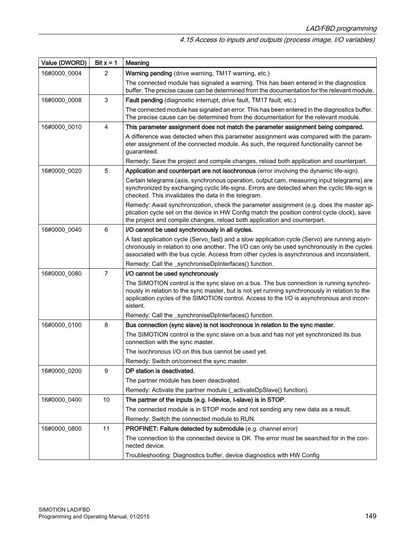
Value (DWORD) Bit x = 1 Meaning16#0000_0004 2 Warning pending (drive warning, TM17 warning, etc.)
The connected module has signaled a warning. This has been entered in the diagnostics buffer. The precise cause can be determined from the documentation for the relevant module.
16#0000_0008 3 Fault pending (diagnostic interrupt, drive fault, TM17 fault, etc.)The connected module has signaled an error. This has been entered in the diagnostics buffer. The precise cause can be determined from the documentation for the relevant module.
16#0000_0010 4 This parameter assignment does not match the parameter assignment being compared.A difference was detected when this parameter assignment was compared with the param‐eter assignment of the connected module. As such, the required functionality cannot be guaranteed.Remedy: Save the project and compile changes, reload both application and counterpart.
16#0000_0020 5 Application and counterpart are not isochronous (error involving the dynamic life-sign).Certain telegrams (axis, synchronous operation, output cam, measuring input telegrams) are synchronized by exchanging cyclic life-signs. Errors are detected when the cyclic life-sign is checked. This invalidates the data in the telegram.Remedy: Await synchronization, check the parameter assignment (e.g. does the master ap‐plication cycle set on the device in HW Config match the position control cycle clock), save the project and compile changes, reload both application and counterpart.
16#0000_0040 6 I/O cannot be used synchronously in all cycles.A fast application cycle (Servo_fast) and a slow application cycle (Servo) are running asyn‐chronously in relation to one another. The I/O can only be used synchronously in the cycles associated with the bus cycle. Access from other cycles is asynchronous and inconsistent.Remedy: Call the _synchroniseDpInterfaces() function.
16#0000_0080 7 I/O cannot be used synchronouslyThe SIMOTION control is the sync slave on a bus. The bus connection is running synchro‐nously in relation to the sync master, but is not yet running synchronously in relation to the application cycles of the SIMOTION control. Access to the I/O is asynchronous and incon‐sistent.Remedy: Call the _synchroniseDpInterfaces() function.
16#0000_0100 8 Bus connection (sync slave) is not isochronous in relation to the sync master.The SIMOTION control is the sync slave on a bus and has not yet synchronized its bus connection with the sync master.The isochronous I/O on this bus cannot be used yet.Remedy: Switch on/connect the sync master.
16#0000_0200 9 DP station is deactivated.The partner module has been deactivated.Remedy: Activate the partner module (_activateDpSlave() function).
16#0000_0400 10 The partner of the inputs (e.g. I-device, I-slave) is in STOP.The connected module is in STOP mode and not sending any new data as a result.Remedy: Switch the connected module to RUN.
16#0000_0800 11 PROFINET: Failure detected by submodule (e.g. channel error)The connection to the connected device is OK. The error must be searched for in the con‐nected device.Troubleshooting: Diagnostics buffer, device diagnostics with HW Config
LAD/FBD programming4.15 Access to inputs and outputs (process image, I/O variables)
SIMOTION LAD/FBDProgramming and Operating Manual, 01/2015 149

Value (DWORD) Bit x = 1 Meaning16#0000_1000 12 PROFINET: Failure detected by module (e.g. submodule failed, removed, etc.)
The connection to the connected device is OK. The error must be searched for in the con‐nected device.Troubleshooting: Diagnostics buffer, device diagnostics with HW Config
16#0000_2000 13 PROFINET: Failure detected by device (e.g. device in STOP, module removed, etc.)The connection to the connected device is OK. The error must be searched for in the con‐nected device.Troubleshooting: Diagnostics buffer, device diagnostics with HW Config
16#0000_4000 14 PROFINET: Failure detected by controller (e.g. not connected, etc.)There is no connection to a partner on PROFINET.Possible cause: Partner is switched off, cable pulled out, incorrect parameter assignment for connectionTroubleshooting: Best to use the PROFINET topology editor in HW Config.
16#0000_8000 15 Slot/subslot is not connected (disconnection alarm).The connection to the connected device is OK. The error must be searched for in the con‐nected device (e.g. module/submodule removed).Troubleshooting: Diagnostics buffer, device diagnostics with HW Config
16#0001_0000 16 Device is not connected (station failure).There is no connection to a partner.Possible cause: Partner is switched off, cable pulled out.
16#0002_0000 17 Substitute value behavior during accessThere is no connection to the counterpart (sum signal from bits 9 to 16), i.e. there is no valid input data or the output data is not reaching the terminal. The substitute value behavior set (substitute value, last value) takes effect during direct access to this address or during proc‐ess image updates.
16#4000_0000 30 Diagnostics address onlyNo cyclic I/O data is configured for this address. It is possible, however, to query submodule diagnostic information.
16#8000_0000 31 Address gapThere is no hardware configured for this logical address.
4.15.4 Access to fixed process image of the BackgroundTask
The fixed process image of the BackgroundTask is a memory area in the RAM of the SIMOTION device on which a subset of the I/O address space of the SIMOTION device is mirrored. Preferably, it should be used for programming the BackgroundTask (cyclic programming) as it is consistent throughout the entire cycle.
LAD/FBD programming4.15 Access to inputs and outputs (process image, I/O variables)
SIMOTION LAD/FBD150 Programming and Operating Manual, 01/2015

The size of the fixed process image of the BackgroundTask for all SIMOTION devices is 64 bytes (address range 0 .. 63).
Note
The fixed process image of the BackgroundTask can be used to access addresses that are not available in the I/O or not configured in HW Config. These are treated like normal memory addresses.
Memory area● As of Version V4.2 of the SIMOTION Kernel, selecting a "Common process image" setting
on the device ensures the memory area for the fixed process image of the BackgroundTask is a subset of the memory area for the process image of the cyclic tasks.I/O addresses can be read and written to using both the fixed process image of the BackgroundTask and the process image of the cyclic tasks.
● With Version V4.1 and lower of the SIMOTION Kernel or the "Separate process image" setting on the device (as of Version V4.2 of the SIMOTION Kernel), the fixed process image of the BackgroundTask and the process image of the cyclic tasks occupy different memory areas.I/O addresses accessed using the process image of the cyclic tasks cannot be read or written to using the fixed process image of the BackgroundTask. They are treated like normal memory addresses.
Table 4-27 Effect of "Common process image" or "Separate process image" settings on the fixed process image of the BackgroundTask
Common process image Separate process imageAvailability Only available as of Version V4.2 of the
SIMOTION Kernel:● Setting available for selection● Standard for newly created devices
Version V4.1 and lower of the SIMO‐TION Kernel applies:● System characteristic, not
configurableThe following applies as of Version V4.2 of the SIMOTION Kernel:● Setting available for selection● Standard with device upgrades
Memory area Subset of the memory area for the proc‐ess image of the cyclic tasks
Separate memory area for the process image of the cyclic tasks
Using I/O addresses accessed using the process image of the cyclic tasks
Possible.Updates use the configured cyclic tasks.
Not supported.The addresses are treated like normal memory addresses.
Byte order when forming the process image
As supplied by the I/O Always Big Endian
Byte order when accessing the process image
Always Big Endian Always Big Endian
Access to I/O operating in the Little En‐dian byte order
Same result as during direct access or for the process image of cyclic tasks (apart from WORD or DWORD data types).
Results differ depending on the I/O var‐iables created for direct access.
LAD/FBD programming4.15 Access to inputs and outputs (process image, I/O variables)
SIMOTION LAD/FBDProgramming and Operating Manual, 01/2015 151

Common process image Separate process imageEffects on the process image of the cy‐clic tasks
See the relevant table in "Direct access and process image of the cyclic tasks (Page 141)".
Further information Common process image (Page 152) Separate process image (Page 154)
For information on the order of the Little Endian and Big Endian bytes, please refer to the SIMOTION Basic Functions Function Manual.
A comparison of the most important properties in comparison to the direct access and process image of the cyclical tasks (Page 141) is contained in "Important properties of direct access and process image (Page 138)".
Note
The rules for I/O addresses for direct access and the process image of the cyclical tasks (Page 144) do not apply. Access to the fixed process image of the BackgroundTask is not taken into account during the consistency check of the project (e.g. during download).
Addresses not present in the I/O or not configured in HW Config are treated like normal memory addresses.
You can access the fixed process image of the BackgroundTask by means of:
● Using an absolute PI access (Page 156): The absolute PI access identifier contains the address of the input/output and the data type.
● Using a symbolic PI access (Page 158): You declare a variable that references the relevant absolute PI access:
– A unit variable
– A static local variable in a program.
● Using an I/O variable (Page 160): In the symbol browser, you define a valid I/O variable for the entire device that references the corresponding absolute PI access.
4.15.4.1 Common process image (as of Kernel V4.2)As of Version V4.2 of the SIMOTION Kernel, the "Common process image" setting can be selected on the SIMOTION device. This means addresses 0 .. 63 of the process image of the cyclic tasks and the fixed process image of the BackgroundTask occupy the same memory area.
This is the default for SIMOTION devices newly created in the project as of Version V4.2.
Property of the common process image1. The memory area for the fixed process image of the BackgroundTask (Page 150) is a
subset of the memory area for the process image of the cyclic tasks (Page 141).
2. This means I/O addresses already accessed using the process image of the cyclic tasks may also continue to be used for the fixed process image of the BackgroundTask. Updates, however, use the configured cyclic tasks.
LAD/FBD programming4.15 Access to inputs and outputs (process image, I/O variables)
SIMOTION LAD/FBD152 Programming and Operating Manual, 01/2015

3. The following applies when forming the fixed process image of the BackgroundTask:The byte order is the same as supplied by the I/O:
– Big Endian, e.g. for I/O via PROFIBUS DP, PROFINET, P‑Bus, DRIVE‑CLiQ
– Little Endian, e.g. for onboard I/O of C240, C240 PN SIMOTION devices
Any I/O variable created for the relevant addresses for the purpose of direct access or the process image of the cyclic tasks has no effect on the byte order.
4. Access to the fixed process image of the BackgroundTask always takes place using the Big Endian byte order.
5. These last two properties (nos. 3 and 4) affect access to inputs and outputs operating with the Little Endian byte order (e.g. onboard I/O of C240, C240 PN SIMOTION devices).If the fixed process image of the BackgroundTask is used for access, this leads to the following behavior, regardless of whether I/O variables have been created for the relevant addresses for the purpose of direct access or the process image of the cyclic tasks:
– Access to individual bytes always supplies the same result via an I/O variable or the fixed process image of the BackgroundTask.
– With the fixed process image of the BackgroundTask, bytes only change places if data type WORD is used for access.
Please also refer to the example below.
For information on the order of the Little Endian and Big Endian bytes, please refer to the SIMOTION Basic Functions Function Manual.
Example for common process image: Access to I/O operating with the Little Endian byte orderThe digital inputs of the C240 SIMOTION device operate with the Little Endian byte order and occupy addresses 66 (bits 0 ..7) and 67 (bits 0.. 3) by default. The start address is changed to 60 in HW Config to ensure it is in the range occupied by the fixed process image of the BackgroundTask. Addresses 60 and 61 are now accessed using various I/O variables and the process image of the BackgroundTask.
The following three scenarios are considered, which differ in terms of whether and which I/O variables are created for direct access or the process image of the cyclic tasks:
1. Scenario A:No I/O variables are created for addresses 60 and 61.
2. Scenario B:Two I/O variables with data type BYTE are created for addresses 60 and 61: io_byte_60 (PIB60) and io_byte_61 (PIB61).
3. Scenario C:For adresss 60, one I/O‑Variable with data type WORD is created; this also covers address 61: io_word_60 (PIW60).
Two additional I/O variables are also created in each of the three scenarios, making it possible to access bit 3: io_bit_60_3 (PI60.3) and io_bit_61_3 (PI61.3).
LAD/FBD programming4.15 Access to inputs and outputs (process image, I/O variables)
SIMOTION LAD/FBDProgramming and Operating Manual, 01/2015 153

The table below lists which values are generated with the following access types:
● Direct access or access to the process image of the cyclic tasks:
– Access to individual bytes or the word using the relevant I/O variables
– Access to each individual byte using the _getInOutByte function (direct access only)
– Access to the respective bit 3 using the relevant I/O variables
● Access to the fixed process image of the BackgroundTask:
– Access to individual bytes using an absolute name
– Access to the word using an absolute name
– Access to the respective bit 3 using an absolute name
Table 4-28 "Common process image" setting (as of Kernel V4.2): Different types of access to the process images of an input operating with the Little Endian byte order
Access using Scenario A 1 Scenario B 1 Scenario C 1
Direct access or access to the process image of the cyclic tasks
io_byte_60 (PIB60) - 16#08 -io_byte_61 (PIB61) - 16#00 -io_word_60 (PIW60) - - 16#0008_getInOutByte (IN, 60) 16#08 16#08 16#08_getInOutByte (IN, 61) 16#00 16#00 16#00io_bit_60_3 (PI60.3) TRUE TRUE TRUEio_bit_61_3 (PI61.3) FALSE FALSE FALSE
Access to the fixed proc‐ess image of the Back‐groundTask
%IB60 16#08 16#08 16#08%IB61 16#00 16#00 16#00%IW60 16#0800 2 16#0800 2 16#0800 2
%I60.3 TRUE TRUE TRUE%I61.3 FALSE FALSE FALSE
1 Scenarios A, B, or C determine whether and which I/O variables are created for direct access or the process image of the cyclic tasks; see the explanation provided in the body of the document.
2 The two bytes in the word change places, as a value saved in the Little Endian byte order is being read using Big Endian.
4.15.4.2 Separate process image (up to Kernel V4.1)With Version V4.1 and below of the SIMOTION Kernel, the process image of the cyclic task and the fixed process image of the BackgroundTask are stored in different memory areas (separate process image).
As of Version V4.2 of the SIMOTION Kernel, the "Separate process image" setting can be selected on the SIMOTION device. This setting ensures there is compatibility with earlier Kernel versions.
It is the default for SIMOTION devices upgraded to Version V4.2 or higher.
LAD/FBD programming4.15 Access to inputs and outputs (process image, I/O variables)
SIMOTION LAD/FBD154 Programming and Operating Manual, 01/2015

Property of the separate process image1. The fixed process image of the BackgroundTask (Page 150) and the process image of the
cyclic tasks (Page 141) are stored in different memory areas.
2. This means I/O addresses that are already accessed using the process image of the cyclic tasks cannot be read or written to using the fixed process image of the BackgroundTask. They are treated like normal memory addresses.
3. I/O variables for direct access influence the fixed process image of the BackgroundTask:
– The fixed process image of the BackgroundTask is always formed for the relevant addresses in the Big Endian byte order.
4. Access to the fixed process image of the BackgroundTask always takes place using the Big Endian byte order.
5. These last two properties (nos. 3 and 4) affect access to inputs and outputs operating with the Little Endian byte order (e.g. onboard I/O of C230‑2, C240, C240 PN SIMOTION devices).If an I/O variable is created for the relevant addresses for the purpose of direct access using data type WORD and access takes place using the fixed process image of the BackgroundTask, this leads to the following behavior:
– Access with the data type WORD supplies the same result via the I/O variable and the fixed process image of the BackgroundTask.
– Access to individual bytes using the _getInOutByte function (see SIMOTION Basic Functions Function Manual) supplies these in the Little Endian order.
– Access to the individual bytes or bits with the fixed process image of the BackgroundTask supplies these in the Big Endian order.
Please also refer to the example below.
For information on the order of the Little Endian and Big Endian bytes, please refer to the SIMOTION Basic Functions Function Manual.
Example for separate process image: Access to I/O operating with the Little Endian byte orderThe digital inputs of the C240 SIMOTION device operate with the Little Endian byte order and occupy addresses 66 (bits 0 ..7) and 67 (bits 0.. 3) by default. The start address is changed to 60 in HW Config to ensure it is in the range occupied by the fixed process image of the BackgroundTask. Addresses 60 and 61 are now accessed using various I/O variables and the process image of the BackgroundTask.
The following three scenarios are considered, which differ in terms of whether and which I/O variables are created for direct access:
1. Scenario A:No I/O variables are created for addresses 60 and 61.
2. Scenario B:Two I/O variables with data type BYTE are created for addresses 60 and 61: io_byte_60 (PIB60) and io_byte_61 (PIB61).
3. Scenario C:For adresss 60, one I/O‑Variable with data type WORD is created; this also covers address 61: io_word_60 (PIW60).
LAD/FBD programming4.15 Access to inputs and outputs (process image, I/O variables)
SIMOTION LAD/FBDProgramming and Operating Manual, 01/2015 155

Two additional I/O variables are also created in each of the three scenarios, making it possible to access bit 3: io_bit_60_3 (PI60.3) and io_bit_61_3 (PI61.3).
The table below lists which values are generated with the following access types:
● Direct access:
– Access to individual bytes or the word using the relevant I/O variables
– Access to each individual byte using the _getInOutByte function
– Access to the respective bit 3 using the relevant I/O variables
● Access to the fixed process image of the BackgroundTask:
– Access to individual bytes using an absolute name
– Access to the word using an absolute name
– Access to the respective bit 3 using an absolute name
Table 4-29 "Separate process image" setting or Kernel up to Version V4.1: Different types of access to the process images of an input operating with the Little Endian byte order
Access using Scenario A 1 Scenario B 1 Scenario C 1
Direct access
io_byte_60 (PIB60) - 16#08 -io_byte_61 (PIB61) - 16#00 -io_word_60 (PIW60) - - 16#0008_getInOutByte (IN, 60) 16#08 16#08 16#08_getInOutByte (IN, 61) 16#00 16#00 16#00io_bit_60_3 (PI60.3) TRUE TRUE TRUEio_bit_61_3 (PI61.3) FALSE FALSE FALSE
Access to the fixed proc‐ess image of the Back‐groundTask
%IB60 16#08 16#08 16#00 3
%IB61 16#00 16#00 16#08 3
%IW60 16#0800 2 16#0800 2 16#0008%I60.3 TRUE TRUE FALSE 3
%I61.3 FALSE FALSE TRUE 3
1 Scenarios A, B, or C determine whether and which I/O variables are created for direct access; see the explanation provided in the body of the document.
2 The two bytes in the word change places, as a value saved in the Little Endian order is being read using Big Endian.
3 The two adjacent bytes change places, as the relevant word is saved in the Big Endian order.
4.15.4.3 Absolute access to the fixed process image of the BackgroundTask (absolute PI access)You make absolute access to the fixed process image of the BackgroundTask (Page 150) by directly using the identifier for the address (with implicit data type). The syntax of the identifier (Page 157) is described in the following section.
LAD/FBD programming4.15 Access to inputs and outputs (process image, I/O variables)
SIMOTION LAD/FBD156 Programming and Operating Manual, 01/2015

You can use the identifier for the absolute PI access in the same manner as a normal variable.
Note
Outputs can be read and written to, but inputs can only be read.
4.15.4.4 Syntax for the identifier for an absolute process image accessFor the absolute access to the fixed process image of the BackgroundTask (Page 156), use the following syntax. This specifies not only the address, but also the data type of the access and the mode of access (input/output).
You also use these identifiers:
● For the declaration of a symbolic access to the fixed process image of the BackgroundTask (Page 158).
● For the creation of an I/O variables for accessing the fixed process image of the BackgroundTask (Page 160).
Table 4-30 Syntax for the identifier for an absolute process image access
Data type Syntax for Permissible address rangeInput Output
BOOL %In.xor%IXn.x 1
%Qn.xor%QXn.x1
n:x:
0 .. 63 2
0 .. 7
BYTE %IBn %QBn n: 0 .. 63 2
WORD %IWn %QWn n: 0 .. 63 2
DWORD %IDn %QDn n: 0 .. 63 2
n = logical addressx = bit number1 The syntax %IXn.x or %QXn.x is not permitted when defining I/O variables.2 For a separate process image (Page 154), the following applies: No addresses that are used in the process image of the cyclic tasks. See note below.
ExamplesInput at logic address 62, WORD data type: %IW62.
LAD/FBD programming4.15 Access to inputs and outputs (process image, I/O variables)
SIMOTION LAD/FBDProgramming and Operating Manual, 01/2015 157

Output at logical address 63, bit 3, BOOL data type: %Q63.3.
Note
Up to Version V4.1 of the SIMOTION Kernel or the "Separate process image" (Page 154) setting on the device (as of Version V4.2 of the SIMOTION Kernel), the following applies:● Addresses accessed using the process image of the cyclic tasks cannot be read or written
to using the fixed process image of the BackgroundTask.
This restriction no longer applies as of Version V4.2 of the SIMOTION Kernel or with the "Common process image" (Page 152) setting on the device.
Note
The rules for I/O addresses for direct access and the process image of the cyclical tasks (Page 144) do not apply. Access to the fixed process image of the BackgroundTask is not taken into account during the consistency check of the project (e.g. during download).
Addresses not present in the I/O or not configured in HW Config are treated like normal memory addresses.
4.15.4.5 Defining symbolic access to the fixed process image of the BackgroundTaskYou create symbolic access to the fixed process image of the BackgroundTask in the declaration tables of the source file, MCC chart, or LAD/FBD program (only in the case of programs). The scope of the symbolic process image access is dependent on the location of the declaration:
● In the interface section of the declaration table of the source file (INTERFACE):Symbolic process image access behaves like a unit variable; it is valid for the entire source file; all MCC charts or LAD/FBD programs (programs, function blocks, and functions) within the source file can access the process image.In addition, these variables are available on HMI devices and, once connected, in other source files (or other units), as well.The total size of all unit variables in the interface section is limited to 64 Kbytes.
● In the implementation section of the declaration table of the source file (IMPLEMENTATION):Symbolic process image access behaves like a unit variable; it is only valid in the source file; all MCC charts or LAD/FBD programs (programs, function blocks, and functions) within the source file can access it.
● In the declaration table for the MCC chart or LAD/FBD program (only in the case of programs):Symbolic process image access behaves like a local variable; it can only be accessed within the MCC chart or LAD/FBD program in which it is declared. No symbolic process image access can be declared in functions or function blocks.
LAD/FBD programming4.15 Access to inputs and outputs (process image, I/O variables)
SIMOTION LAD/FBD158 Programming and Operating Manual, 01/2015

Proceed as follows; the source file or the MCC chart or LAD/FBD program (in the case of programs only) with the declaration table is opened:
1. Select the declaration table and, if applicable, the section of the declaration table for the desired scope.
2. Select the I/O Symbols tab.
3. Enter:
– Name of symbol (variable name)
– For Absolute ID, the identifier of the absolute process image access (Page 157).
– Data type of symbol (Page 159) (this must agree with the length of the process image access).
4.15.4.6 Possible data types for symbolic PI accessIn the following cases, a data type that differs from that of the absolute PI access can be assigned to the fixed process image of the BackgroundTask (Page 150). The data type width must correspond to the data type width of the absolute PI access.
● For the declaration of a symbolic PI access (Page 158).
● For the creation of an I/O variable (Page 160).
If you assign a numeric data type to the symbolic PI access or to the I/O variables, you can access these variables as integer.
Table 4-31 Possible data types for symbolic PI access
Data type of theabsolute PI access
Possible data types of the symbolic PI access
BOOL (%In.x, %IXn.x, %Qn.x. %QXn.x) BOOLBYTE (%IBn, %QBn) BYTE, SINT, USINTWORD (%IWn, %QWn) WORD, INT, UINTDWORD (%IDn, %PQDn) DWORD, DINT, UDINT
For the data type of the absolute PI access, see also "Syntax for the identifier for an absolute PI access (Page 157)".
4.15.4.7 Example: Defining symbolic access to the fixed process image of the BackgroundTask
Figure 4-36 Example: Defining symbolic access to the fixed process image of the BackgroundTask
LAD/FBD programming4.15 Access to inputs and outputs (process image, I/O variables)
SIMOTION LAD/FBDProgramming and Operating Manual, 01/2015 159

4.15.4.8 Creating an I/O variable for access to the fixed process image of the BackgroundTaskYou create I/O variables for access to the fixed process image for the background task in the symbol browser in the detail view; you must be in offline mode to do this.
Here is a brief overview of the procedure:
1. Select the "Address list" tab in the detail view and choose the SIMOTION deviceorIn the project navigator of SIMOTION SCOUT, double-click the "ADDRESS LIST" element in the SIMOTION device subtree.
2. Select the line before which you want to insert the I/O variable and, from the context menu, select Insert new lineorScroll to the end of the table of variables (empty line).
3. In the detail view, select the Symbol browser tab and scroll down to the end of the variable table (empty row).
4. In the empty row of the table, enter or select the following:
– Name of variable.
– Under I/O address, the absolute PI access according to the "Syntax for the identifier for an absolute PI access" (Page 157) (exception: The syntax %IXn.x or %QXn.x is not permitted for data type BOOL).
– Data type of the I/O variables according to the "Possible data types of the symbolic PI access" (Page 159).
5. Select optionally the display format used to monitor the variable in the symbol browser.
You can now access this variable using the address list or any program of the SIMOTION device.
Note
I/O variables can only be created in offline mode. You create the I/O variables in SIMOTION SCOUT and use them in your program sources.
Note that you can read and write outputs but you can only read inputs.
Before you can monitor and modify new or updated I/O variables, you must download the project to the target system.
You can use I/O variables like any other variable, see "Access I/O variables" (Page 160).
4.15.5 Accessing I/O variablesYou have created an I/O variable for:
● Direct access or process image of the cyclic tasks (Page 141).
● Access to the fixed process image of the BackgroundTask (Page 150).
LAD/FBD programming4.15 Access to inputs and outputs (process image, I/O variables)
SIMOTION LAD/FBD160 Programming and Operating Manual, 01/2015

You can use this I/O variable just like any other variable.
Note
Consistency is only ensured for elementary data types.
When using arrays, the user is responsible for ensuring data consistency.
Note
If you have declared unit variables or local variables of the same name (e.g. var-name), specify the I/O variable using _device.var-name (predefined name space, see the "Predefined name spaces" table in "Name spaces").
It is possible to directly access an I/O variable that you created as a process image of a cyclic task. Specify direct access with _direct.var-name or _device._direct.var-name.
If you want to deviate from the default behavior when errors occur during variable access, you can use the _getSafeValue and _setSafeValue functions (see SIMOTION Basic Functions Function Manual).
For Errors associated with access to I/O variables, see SIMOTION Basic Functions Function Manual.
LAD/FBD programming4.15 Access to inputs and outputs (process image, I/O variables)
SIMOTION LAD/FBDProgramming and Operating Manual, 01/2015 161

4.16 Connections to other program source files or librariesIn the declaration table of a unit, you can define connections to:
● LAD/FBD units under the same SIMOTION device
● MCC units under the same SIMOTION device
● ST source files under the same SIMOTION device
● Libraries
This will then allow you to access the following in this unit:
● For connected program sources (Page 163), the following items which are defined there
– Functions
– Function blocks
– Programs (optional)
– Unit variables
– User-defined data types (structures, enumerations)
– Symbolic accesses to the fixed process image of the BackgroundTask
● For connected libraries (Page 163), the following items which are defined there
– Functions
– Function blocks
– Programs (optional)
– User-defined data types (structures, enumerations)
Program sources and libraries must be compiled beforehand.
For information about the library concept, see also the SIMOTION ST Programming Manual.
Note
Libraries can be created in all programming languages (MCC, ST, or LAD/FBD).
LAD/FBD programming4.16 Connections to other program source files or libraries
SIMOTION LAD/FBD162 Programming and Operating Manual, 01/2015

4.16.1 Defining connections
4.16.1.1 Procedure for defining connections to other program sources (units) Connections to other units (program sources) are defined in the declaration table of the source file. The mode of action of a connection is dependent on the section of the declaration table in which it is defined.
● In the interface section of the declaration table:The imported functions, variables, etc., will continue to be exported to other units and to HMI devices. This can lead to name conflicts.This setting is necessary, for example, if unit variables are declared in the interface section of the source file with a data type that is defined in the imported program source.
● In the implementation section of the declaration table:The imported functions, variables, etc. will no longer be exported.This setting is usually sufficient.
Proceed as follows; the source file (declaration table) is open (see Open existing program sources (Page 51)):
1. In the declaration table, select the section for the desired mode of action.
2. Select the Connections tab.
3. For the connection type, select: Program/Unit
4. In the same line, select the name of the unit to be connected:Units (program sources) must be compiled beforehand.
4.16.1.2 Procedure for defining connections to librariesConnections to libraries are defined in the declaration table of the source file.
Proceed as follows; the unit (declaration table) is open, see Open existing program sources (Page 51):
1. In the interface section of the declaration table, select the Connections tab.
2. For the connection type, select: Library.
3. In the same line, select the name of the library to be connected.Libraries must be compiled beforehand.
4. Optionally, you can define a name space for libraries, see Using name space (Page 164):To do this, enter a name under Name space.
Note
When programming the "Subprogram call" command (see Inserting and parameterizing subroutine calls (Page 167)) with a library function or a library function block, the connection to the library is automatically entered into the declaration table of the program source.
LAD/FBD programming4.16 Connections to other program source files or libraries
SIMOTION LAD/FBDProgramming and Operating Manual, 01/2015 163

4.16.2 Using the name spaceYou can optionally assign a name space to every connected library. You define the designation of the name space when connecting the library (see How to define connections to libraries (Page 163)).
It is important to specify the name space if the current LAD/FBD program/MCC chart or program source contains variables, data types, functions, or function blocks with the same name as the connected library. The name space will then allow you specific access to the variables, data types, functions, or function blocks in the library. This can also resolve naming conflicts between connected libraries.
If you wish to use variables, data types, functions, or function blocks from the connected library in a command in the LAD/FBD program or MCC chart, insert the designation of the name space in front of the variable name, etc., from the library and separate them with a period (for example, namespace.var_name, namespace.fc_name).
Name spaces are predefined for device-specific and project-specific variables, direct accesses to I/O variables, and variables of TaskId and AlarmId in the following table: If necessary, write their designation before the variable name, separated by a period, e.g. _device.var_name or _task.task_name.
Table 4-32 Predefined name spaces
Name space Description_alarm For AlarmId: The _alarm.name variable contains the AlarmId of the message with
the name identifier – see SIMOTION Basic Functions Function Manual._device For device-specific variables (global device user variables, I/O variables, system
variables, and system variables of the SIMOTION device)_direct For direct access to I/O variables – see Direct access and process image of the cyclic
tasks (Page 141).Local name space for _device. Nesting as in _device._direct.name is permitted.
_project For names of SIMOTION devices in the project; only used with technology objects on other devices.With unique project-wide names of technology objects, used also for these names and their system variables
_quality As of Version V4.2 of the SIMOTION Kernel: For the detailed status of I/O varia‐bles (Page 148). A value with data type DWORD is supplied.Local name space for _device. Nesting as in _device._quality.name is permitted.
_task For TaskID: The _task.name variable contains the TaskId of the task with the name identifier – see SIMOTION Basic Functions Function Manual.
_to For technology objects configured on the SIMOTION device and their system varia‐bles and configuration dataNot for system functions and data types of the technology objects. In this case, use the user-defined name space for the imported technology package, if necessary.
LAD/FBD programming4.16 Connections to other program source files or libraries
SIMOTION LAD/FBD164 Programming and Operating Manual, 01/2015
4.17 SubroutineUniversal, reusable sections of a program can be created in the form of subroutines.
When a subroutine is called, the program branches from the current task into the subroutine. The commands in the subroutine are executed. The program then jumps back to the previously active task.
Subroutines can be called repeatedly, as required, by one or more LAD/FBD programs of the SIMOTION device.
Subroutine as a function (FC), function block (FB), or program The creation type of a subroutine can be a function (FC), a function block (FB) or, as an option, a program ("program in program").
● FunctionA function (FC) is a subroutine without static data, that is, all local variables lose their value when the function has been executed. They are re-initialized when the function is next started.Data are transferred to the function using input or in/out parameters; the output of a function value (return value) is also possible.
● Function blockA function block (FB) is a subroutine with static data, that is, local variables retain their value after the function block has been executed. Only variables that have been explicitly declared as temporary lose their value.An instance has to be defined before using an FB: Define a variable (VAR or VAR_GLOBAL) and enter the name of the FB as data type. The FB static data is saved in this instance. You can define several FB instances; each instance is independent from the others.The static data of an FB instance remain stored until the instance is next called; they are reinitialized when the variable type of the FB instance is initialized again (see Initialization of instances of function blocks (FB) (Page 130)).Data are transferred to the FB using input parameters or in/out parameters; the data are returned from the FB using in/out or output parameters.
● Program ("program in program")You also have the option of calling a program within a different program or a function block. This requires the following compiler options to be activated (see Global compiler settings (Page 60) and Local compiler settings (Page 60)):
– "Permit language extensions" for the program source of the calling program or function block and
– "Only create program instance data once" for the program source of the called program. The static data of the called program is stored in the user memory of the program source (unit) of said called program.
Most of the programming work involved in assigning the programs to the tasks can be performed by calling up programs within another program. In the execution system, only one associated calling program needs to be assigned to the tasks concerned.A program is called without parameters or return values.Further information on calling a program within a program can be found in the ST Programming and Operating Manual.
LAD/FBD programming4.17 Subroutine
SIMOTION LAD/FBDProgramming and Operating Manual, 01/2015 165

Note
The activated "Only create program instance data once" compiler option causes:● The static variables of the programs (program instance data) to be stored in the user
memory of the program source (unit) (see the SIMOTION ST Programming and Operating Manual). This also causes the initialization behavior to change (see the SIMOTION ST Programming and Operating Manual).
● All called programs with the same name to use the same program instance data.
Exchange of information between the subroutine and calling program Function (FC) and function block (FB) as a subroutine
Information is exchanged between the subroutine and the calling program using transfer parameters or global variables (e.g. unit variables).
Transfer parameters can be input, input/output or output parameters. They are defined in the declaration table for the subroutine:
● Input parameters: As variable type VAR_INPUT
● In/out parameter: As variable type VAR_IN_OUT
● Output parameter (for FB only): As variable type VAR_OUTPUT
For functions, a function value can be returned; you specify the data type of the return value when you paste in (create) the function (see Paste in function (FC) or function block (FB) (Page 167)).
You assign current values to the input and/or in/out parameters when you call the subroutine (FC or FB instance). You may only assign user-defined variables to the in/out parameters of an FB because the called FB accesses the assigned variables directly and can therefore change them.
The output parameters of an FB can be read-accessed as often as required in the calling program.
A function does not formally contain any output parameters, since the result of the function can in this case be assigned to the return value of the function.
See also the examples of functions (Page 170) and function blocks (Page 175).
Program as subroutine ("program in program")
A program is called without parameters or return values. This means that information can only be exchanged between the calling program and the called program (subroutine) using global variables (e.g. unit variables).
See alsoInserting a subroutine call into the LAD/FBD program and assigning parameters (Page 167)
LAD/FBD programming4.17 Subroutine
SIMOTION LAD/FBD166 Programming and Operating Manual, 01/2015

4.17.1 Inserting a function (FC) or function block (FB)The creation dialog is similar to that of an LAD/FBD program:
1. LAD/FBD unit must already exist (see Managing LAD/FBD programs (Page 64)).
2. In the project navigator, open the relevant LAD/FBD unit.
3. Double-click the entry Insert LAD/FBD program.The input screen form opens.
– Enter the name of the LAD/FBD program (see Rules for identifiers (Page 99)).
– For the creation type, select Function or Function block.
– With creation type Function only:Select the data type of the return value as the return type (<--> for no return value).
– Check the Exportable option if the function or function block is to be used in other program source files (LAD/FBD, MCC or ST source files).When the checkbox is cleared, the LAD/FBD program can only be used in the associated LAD/FBD unit.
– You can also enter an author, version, and a comment.
– Confirm with OK.
4. Program the instructions in the function or function block.Assign an expression to the return value of a function (= function name) or to the output parameters of a function block.
5. Accept and compile the LAD/FBD unit. The subroutine you have created will then be displayed in the list.
4.17.2 Inserting a subroutine call into the LAD/FBD program and assigning parameters
In order to execute a call of a subroutine (function, function block, or program), the relevant subroutine must have been inserted into the network of an LAD/FBD program from the project navigator using drag-and-drop. When the subroutine inserted into the network is reached during a program run, the subroutine is called and the program branches from the current task into the subroutine.
You can use drag-and-drop to insert the following FCs, FBs, and programs into an LAD/FBD program and call them as a subroutine:
● Functions, function blocks, or programs of the same LAD/FBD unit or a different program source (e.g. MCC unit, ST source file).
● Library functions or library function blocks from a program library.
The subroutine call is parameterized, i.e. specifications are made as to which variables are to be transferred when the subroutine is called and returned once it has been executed, in the Enter Call Parameter parameter screen form.
LAD/FBD programming4.17 Subroutine
SIMOTION LAD/FBDProgramming and Operating Manual, 01/2015 167

Figure 4-37 Parameterization of a function's subroutine call
NoteSaving a project in a format older than Version V4.2 of SIMOTION SCOUT
Pay attention to the order of the LAD/FBD programs in an LAD/FBD unit. A subroutine (function, function block, or program ("program in program")) must be defined before it is used. This is the case when the subroutine appears above the LAD/FBD program in which it is used in the project navigator. If necessary, reorder the LAD/FBD programs.
See also: Subroutine call of the function (FC) (Page 172)
Note
The term "LAD/FBD program" is a generic term and may refer to a program, a function (FC), or a function block (FB).
4.17.2.1 Overview of parameters forYou can set the following parameters when parameterizing the subroutine call:
LAD/FBD programming4.17 Subroutine
SIMOTION LAD/FBD168 Programming and Operating Manual, 01/2015

Overview of Subroutine call parameters
Field/Button Explanation/instructionsSubroutine type/Subroutine
The type and name of the subroutine are displayed here:Function(default value)A function is a calculation subroutine that supplies a defined result as a return value based on the parameter entered. Functions have no memory beyond the call.Function blockA function block is a subroutine that can have several return values. A function block corresponds to a data type. Instances are defined. They have a memory, that is, they retain instance data of a function block extending over several calls. Return values of the call can also be scanned in the instance.Program ("program in program")You also have the option of calling a program within a different program or a function block.This requires the following compiler options to be activated (see Global com‐piler settings (Page 60) and Local compiler settings (Page 60)):● "Permit language extensions" for the program source of the calling
program or function block and● "Only create program instance data once" for the program source of the
called program. The static data of the called program is stored in the user memory of the program source (unit) of said called program. The same program instance data is used every time the program is called.
A program is called without parameters or return values.Return value In the case of a function-type subroutine:
Here, you enter the variable in which the return value is to be stored. The type of variable must match the return value type.
Type In the case of a function-type subroutine:The data type of the return value is displayed.
Instance In the case of a function block-type subroutine:Here, enter the name of the function block instance. The instance contains the memory of the function block in the form of instance data.You define the instance as a variable whose data type is the name of the function block in one of the following ways:● In the declaration table of the LAD/FBD unit as VAR_GLOBAL● In the declaration table of the LAD/FBD program as VAR
List of transfer parametersName The name of the transfer parameter is displayed here.On / Off The variable type of the transfer parameter is displayed here.
VAR_INPUTInput parameter (for functions and function blocks)VAR_IN_OUTIn/out parameter (for functions and function blocks)VAR_OUTPUTOutput parameter (for function blocks only)
LAD/FBD programming4.17 Subroutine
SIMOTION LAD/FBDProgramming and Operating Manual, 01/2015 169

Field/Button Explanation/instructionsData type The data type of the transfer parameter is displayed here.Value Mandatory parameters are marked with "<???>" and optional parameters with
"...", with the following applying to functions (FCs):● Transfer parameters without a declared initial value are shown as
mandatory parameters.● Transfer parameters with a declared initial value are shown as optional
parameters.A subroutine call will only be functional if all the mandatory parameters are set. Function blocks (FBs) only have optional parameters. Called programs ("program in program") have no parameters.Here, you can assign current variables or values to the transfer parameters:● Input parameter (variable type VAR_IN):
Here, you enter a variable name or an expression. The assignment of system variables or I/O variables is permissible; type transformations are possible.
● In/out parameter (variable type VAR_IN):Enter a variable name; the variable must be directly writable and readable. System variables of SIMOTION devices and technology objects are not permitted nor are I/O variables. The data type of the in/out parameter must correspond to that of the assigned variables; application of type transformation functions is not possible.
● Output parameter (variable type VAR_OUTPUT – for FB only):The assignment of an output parameter to a variable in this parameter screen form is optional; you can also access an output parameter after executing the function block.When assigned in this parameter screen form: Enter a variable name. The data type of the output parameter must correspond to that of the assigned variables; the application of type transformation functions is not possible.
4.17.3 Example: Function (FC)
You want to create a subroutine with a circumference calculation for a circle. The calculation is performed in a function (FC). This is named Circumference.
The circle circumference calculation can thus be called as a subroutine by any task.
Formula for circumference calculation: Circumference = PI * 2 * radius
You define the Radius and PI variables in the declaration table of the function.
LAD/FBD programming4.17 Subroutine
SIMOTION LAD/FBD170 Programming and Operating Manual, 01/2015

4.17.3.1 Creating and programming the function (FC) 1. In the project navigator, open the LAD/FBD unit in which you want to create the function.
2. Double-click the entry Insert LAD/FBD program.
– Enter the name Circumference.
– For creation type, select Function.
– For return type (data type of return value), select REAL.
– Click OK to confirm.
3. In the declaration table, define the radius input parameters, the diameter parameter, and the PI constant.
Figure 4-38 Declaring variables (e.g. input parameters) in the LAD/FBD program
4. Click the Insert Network button on the LAD editor toolbar.A network is inserted into the Circumference function.
5. Drag the LAD/FBD element MUL from the command library and drop it into the network of the circumference function twice.
6. Program the circumference calculation for the return value by assigning the variables accordingly to the input/output parameters of the two MUL LAD/FBD elements.
Figure 4-39 Programming the Circumference subroutine (e.g. assignment to a return value)
7. Accept and compile the LAD/FBD unit.
LAD/FBD programming4.17 Subroutine
SIMOTION LAD/FBDProgramming and Operating Manual, 01/2015 171

You have now finished programming the Circumference function.
Note
The term "LAD/FBD program" is a generic term and may refer to a program, a function (FC), or a function block (FB).
4.17.3.2 Subroutine call of function (FC)The function (FC) is called from a program in the example.
1. Create an LAD/FBD program as a program in the same LAD/FBD unit (see Inserting a new LAD/FBD program (Page 64)):
– Enter the name Program_circumference.
– For creation type, select Program.
– Click OK to confirm.
2. Declare the following in the LAD/FBD unit or the LAD/FBD program:
– The mycircum variable. The return value of the "Circumference" function is assigned to this variable.
– The myradius variable. This variable contains the radius and is assigned to the input parameter Radius of the Circumference function.
Note that the validity range of the variables is dependent on the declaration location (see Define variables (Page 114)).
① You can continue to use the myumfang (mycircum) variable in the program.
Figure 4-40 Declaring a variable in the LAD/FBD program
3. Click the Insert Network button on the LAD editor toolbar.A network is inserted into the Program_circumference program.
4. Drag the Circumference function from the project navigator and drop it into the network of the Program_circumference program.
5. Select the inserted function, Circumference, followed by the Parameterize call command from the context menu.
LAD/FBD programming4.17 Subroutine
SIMOTION LAD/FBD172 Programming and Operating Manual, 01/2015

6. Assign parameters to the subroutine call in the Enter Call Parameter parameter screen form.
Figure 4-41 Opened parameter screen form for assigning parameters to the subroutine call
Note
Mandatory parameters are marked with "<???>" and optional parameters with "...". A subroutine call will only be functional if all the mandatory parameters are set.
7. Accept and compile the LAD/FBD unit.
You have now finished programming the subroutine call.
Note
The term "LAD/FBD program" is a generic term and may refer to a program, a function (FC), or a function block (FB).
LAD/FBD programming4.17 Subroutine
SIMOTION LAD/FBDProgramming and Operating Manual, 01/2015 173

NoteSaving a project in a format older than Version V4.2 of SIMOTION SCOUT
Pay attention to the order of the LAD/FBD programs in the LAD/FBD unit (see figure below). A subroutine (function, function block, or program ("program in program")) must be defined before it is used. This is the case when the MCC chart of the subroutine appears in the project navigator above the chart in which it is used.
As far as the example described here is concerned, the LAD/FBD program with the function (FC) must appear in the project navigator above the LAD/FBD program containing the program with the subroutine call.
In other words, the circumference function must be positioned above the program_circumference program in the project navigator. If necessary, reorder the LAD/FBD programs by selecting the relevant LAD/FBD program in the project navigator, then selecting the Down or Up command in the context menu.
① Circumference function② Program_circumference program, which contains the subroutine call of the Circumference func‐
tion
Order of LAD/FBD programs
LAD/FBD programming4.17 Subroutine
SIMOTION LAD/FBD174 Programming and Operating Manual, 01/2015

4.17.3.3 Opening the function (FC) directly from the subroutine callYou can open subprograms directly from their respective subprogram call by using the context menu:
● This works regardless of the programming language (ST, MCC, LAD/FBD) used to create the subprogram.
● The subprogram opens in a separate editor or an editor already opened for the subprogram is moved to the foreground.
A subprogram may be a:
● User-defined function (FC)
● User-defined function block (FB)
● User-defined program called as a subprogram ("program in program")
● Library function
● Library function block
● Library program called as a subprogram ("program in program")
ProcedureTo open the FC directly from the subprogram call, proceed as follows:
1. In the LAD/FBD network, select the subprogram call used to call the FC.
2. Select the Open called block command in the context menu (Ctrl+Alt+O shortcut).
The FC opens in a separate editor or an editor already opened for the FC is moved to the foreground.
Note
If the called FC has not yet been created, the Open called block command appears inactive (grayed out) in the context menu.
Note
If the called FC is in a program source with know-how protection, the same steps that apply when opening the protected program source directly also apply here (see Know-how protection for LAD/FBD units (Page 53)).
4.17.4 Example: Function block (FB)
You want to calculate a following error. The calculation is performed in a function block (FB) named FollError. The following error calculation can thus be called as a subroutine by any task.
Formula for following error calculation: Difference = Specified position – Actual position
LAD/FBD programming4.17 Subroutine
SIMOTION LAD/FBDProgramming and Operating Manual, 01/2015 175

Define the required input and output parameters Set position, Actual position, and Difference (with the other variables, if necessary) in the LAD/FBD program (function block) or LAD/FBD unit.
4.17.4.1 Creating and programming the function block (FB)1. In the project navigator, open the LAD/FBD unit in which you want to create the function
block.
2. Double-click the entry Insert LAD/FBD program.
– Enter the name FollError.
– For creation type, select Function block.
– Confirm with OK.
3. In the declaration table, define the variables (e.g. input and output parameters).
Figure 4-42 Declaring variables (e.g. input and output parameters) in the LAD/FBD program
4. Click the Insert network button on the LAD editor toolbar.A network is inserted into the FollError function block.
5. Drag the LAD/FBD element SUB from the command library and drop it into the network of the FollError function block.
6. Program the following error calculation by assigning the variables accordingly to the input/output parameters of the SUB LAD/FBD element.
Figure 4-43 Programming the following error calculation
7. Accept and compile the LAD/FBD unit.
LAD/FBD programming4.17 Subroutine
SIMOTION LAD/FBD176 Programming and Operating Manual, 01/2015

You have now finished programming the FollError function block.
Note
The term "LAD/FBD program" is a generic term and may refer to a program, a function (FC), or a function block (FB).
4.17.4.2 Subroutine call of function block (FB)In this example, the function block (FB) is called from a program.
1. Create an LAD/FBD program as a program (see Inserting a new LAD/FBD program (Page 64)).
2. Create a function block instance.
– In the LAD/FBD unit or LAD/FBD program, declare the instances of the function block along with the variables.
Note that the validity range of the instance and variables is dependent on the declaration location (see Define variables (Page 114)).
3. Call the function block:
– Program the subroutine call.
4. After executing an instance of the function block, you can access the output parameters at any location in the calling program.
– Program the MOVE command.
5. Accept and compile the program.
You have now finished programming the subroutine call.
4.17.4.3 Creating a function block instanceBefore you can use a function block, you must define an instance. Each instance of an FB is independent of the others; once an instance has ended, its static variables remain stored.
LAD/FBD programming4.17 Subroutine
SIMOTION LAD/FBDProgramming and Operating Manual, 01/2015 177

Instances of an FB are defined in the declaration tables of the LAD/FBD unit or of the LAD/FBD program. The scope of the instance declaration is dependent on the location of the declaration:
● In the interface section of the declaration table of the LAD/FBD unit:The instance behaves like a unit variable; it is valid for the entire LAD/FBD unit; all LAD/FBD programs (programs, function blocks, and functions) within the LAD/FBD unit can access the instance.In addition, the instance is available on HMI devices and, once connected (see How to define connections to other units (program source files) (Page 163)), in other LAD/FBD units (or other units), as well.The total size of all unit variables in the interface section is limited to 64 Kbytes.
● In the implementation section of the declaration table of the LAD/FBD unit:The instance behaves like a unit variable which is only valid in the LAD/FBD unit; all LAD/FBD programs (programs, function blocks, and functions) within the LAD/FBD unit can access the instance.
● In the declaration table of the LAD/FBD program (for programs and function blocks only):The instance behaves like a local variable; it can only be accessed within the LAD/FBD program in which it is declared.
Proceed as follows; the LAD/FBD unit or the LAD/FBD program with the declaration table is open (see Open existing LAD/FBD unit (Page 51) or Open existing LAD/FBD program (Page 66)):
1. Select the declaration table and, if applicable, the section of the declaration table for the desired scope.
2. Select the Parameter tab.
3. Enter or select the following:
– Name of instance (variable name – see Rules for identifiers (Page 99))
– Variable type VAR or VAR_GLOBAL, depending on the declaration location (in LAD/FBD program or LAD/FBD unit, respectively)
– Designation of the function block as data type.
4. Declare the other variables.
LAD/FBD programming4.17 Subroutine
SIMOTION LAD/FBD178 Programming and Operating Manual, 01/2015

① The output parameter Difference is assigned to the variable Result_2 during subsequent pro‐gram runtime. You can use the Result_2 variable for other purposes in the program.
② The output parameter Difference is assigned to the variable Result in the subroutine call. You can use the Result variable for other purposes in the program.
③ Creating an instance④ Select the required FB as the data type.
The created function blocks are offered as data types in the drop-down list box depending on the LAD/FBD editor settings (Page 44):● Only function blocks with the same program source or from connected program sources or
libraries● All function blocks defined in the project
Figure 4-44 Defining an instance of the function block and variables in the LAD/FBD program or the LAD/FBD unit
4.17.4.4 Programming the subroutine call of the function block1. Drag the FollError function block from the project navigator and drop it into the network of
the program_FollError LAD/FBD program.
2. Select the inserted function block, FollError, followed by the Display > All Box Parameters command from the context menu.All the input/output parameters of the inserted function block FollError are shown.
3. Select the inserted function block, FollError, followed by the Parameterize call command from the context menu.
LAD/FBD programming4.17 Subroutine
SIMOTION LAD/FBDProgramming and Operating Manual, 01/2015 179
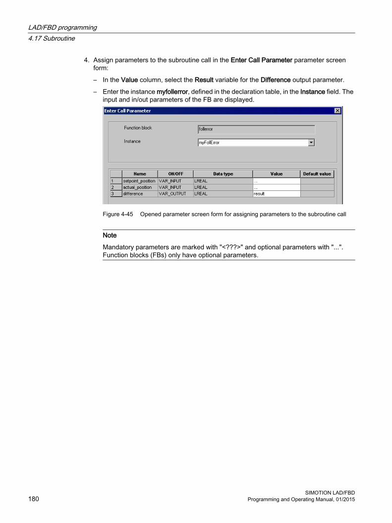
4. Assign parameters to the subroutine call in the Enter Call Parameter parameter screen form:
– In the Value column, select the Result variable for the Difference output parameter.
– Enter the instance myfollerror, defined in the declaration table, in the Instance field. The input and in/out parameters of the FB are displayed.
Figure 4-45 Opened parameter screen form for assigning parameters to the subroutine call
Note
Mandatory parameters are marked with "<???>" and optional parameters with "...". Function blocks (FBs) only have optional parameters.
LAD/FBD programming4.17 Subroutine
SIMOTION LAD/FBD180 Programming and Operating Manual, 01/2015

5. Click OK to confirm.
6. Assign the current values to the transfer parameters:
– Input parameters: Variable or expression
– In/out parameter: Directly readable/writable variable
– Output parameter (optional): Variable
You can use drag-and-drop to assign unit variables and system variables from the detail view to the input, output, or in/out parameters of the instance of the FollError function block inserted into the LAD/FBD network.
Figure 4-46 Assigning system variables from the detail view to the transfer parameters using drag-and-drop
Note
Mandatory parameters are marked with "<???>" in the LAD/FBD network and optional parameters with "...". Function blocks (FBs) only have optional parameters.
Note
The term "LAD/FBD program" is a generic term and may refer to a program, a function (FC), or a function block (FB).
LAD/FBD programming4.17 Subroutine
SIMOTION LAD/FBDProgramming and Operating Manual, 01/2015 181

NoteSaving a project in a format older than Version V4.2 of SIMOTION SCOUT
Pay attention to the order of the LAD/FBD programs in the LAD/FBD unit. A subroutine (function, function block, or program ("program in program")) must be defined before it is used. This is the case when the LAD/FBD program of the subroutine appears in the project navigator above the LAD/FBD program in which it is used.
As far as the example described here is concerned, the LAD/FBD program with the function block (FB) must appear in the project navigator above the LAD/FBD program containing the program with the subroutine call.
In other words, the distance function block must be positioned above the program_distance program in the project navigator. If necessary, reorder the LAD/FBD programs by selecting the relevant LAD/FBD program in the project navigator, then selecting the Down or Up command in the context menu.
See also: Subroutine call of the function (FC) (Page 172).
4.17.4.5 Opening the function block (FB) directly from the subroutine callYou can open subprograms directly from their respective subprogram call by using the context menu:
● This works regardless of the programming language (ST, MCC, LAD/FBD) used to create the subprogram.
● The subprogram opens in a separate editor or an editor already opened for the subprogram is moved to the foreground.
A subprogram may be a:
● User-defined function (FC)
● User-defined function block (FB)
● User-defined program called as a subprogram ("program in program")
● Library function
● Library function block
● Library program called as a subprogram ("program in program")
ProcedureTo open the FB directly from the subprogram call, proceed as follows:
1. In the LAD/FBD network, select the subprogram call used to call the FB.
2. Select the Open called block command in the context menu (Ctrl+Alt+O shortcut).
LAD/FBD programming4.17 Subroutine
SIMOTION LAD/FBD182 Programming and Operating Manual, 01/2015

The FB opens in a separate editor or an editor already opened for the FB is moved to the foreground.
Note
If the called FB has not yet been created, the Open called block command appears inactive (grayed out) in the context menu.
Note
If the called FB is in a program source with know-how protection, the same steps that apply when opening the protected program source directly also apply here (see Know-how protection for LAD/FBD units (Page 53)).
4.17.4.6 Accessing the output parameters of the function block retrospectivelyAfter an instance of the function block has been executed, the static variables of the function block (including the output parameters) are retained. You can access the output parameters at any point in the calling program.
If you have defined the FB instance as VAR_GLOBAL, you can also access the output parameter in other LAD/FBD programs.
1. Insert the MOVE command into the LAD/FBD program.
2. Program the command (see figure).
LAD/FBD programming4.17 Subroutine
SIMOTION LAD/FBDProgramming and Operating Manual, 01/2015 183

① Name of the FB instance ② Output parameter
Figure 4-47 Programming a variable assignment
4.17.5 Limitations with advance signal switchingAn output from an LAD/FBD element can only be connected in advance of an LAP/FBD element input if both the input and output are of data type BOOL. As a result, only Boolean advance signal switching is possible in a network.
An output parameter from an FB or a return value from an FC cannot be switched to an input parameter of a different FB/FC, i.e. Boolean advance signal switching is not possible here either.
Non-Boolean advance signal switching and output/input parameter switching with the FB/FC can be implemented with the aid of an additional network and a temporary variable. If the output from an LAD/FBD element cannot be assigned directly to the input of the other LAD/FBD element, then the former LAD/FBD element is added to this additional network. The same temporary variable is assigned to both output and input, and so the output and input are switched via the temporary variable.
Alternatively, this can also be implemented with just one network and a temporary variable, with the result that both LAD/FBD elements are in the same network.
LAD/FBD programming4.17 Subroutine
SIMOTION LAD/FBD184 Programming and Operating Manual, 01/2015

Example of output/input parameter switching with FB/FCIn the ST programming language, with TO commands from the commands library the "commandid" input parameter can be assigned directly with the _getcommandid function.
This output/input parameter switch with FB/FC can be implemented in the LAD/FBD programming language with an additional network for the _getcommandid function and a temporary variable.
The _getcommandid function is added to the upper network, and the temporary variable "var_commandid" is assigned to its output "OUT". The TO command _pos is added to the lower network, and the temporary variable "var_commandid" is likewise assigned to its input "commandid". The switching of the output "OUT" of _getcommandid and of the input "commandid" of _pos is thus effected using the temporary variable.
Figure 4-48 Output/input parameter switching with FB/FC
4.17.6 Interface adjustment with FB/FCIf the properties of an FB/FC that has been added to the network are modified, then in the following cases there will be an interface adjustment:
1. One or more new input/output parameters are added
2. One or more unused input/output parameters are deleted
3. One or more used input/output parameters are deleted
In cases 1 and 2 the network is updated immediately when it is opened in the LAD/FBD editor, or immediately after it is opened.
In case 3 the FB/FC call is shown in red in the network, and a manual update must be carried out. An existing Boolean advance switching of a deleted input parameter is not deleted; instead it is merely separated off and, for instance, shown in the LAD display as an as an open ladder diagram in the network.
LAD/FBD programming4.17 Subroutine
SIMOTION LAD/FBDProgramming and Operating Manual, 01/2015 185

Manual update of a specific FB/FC callTo manually update a particular FB/FC call, follow these steps:
1. Click on the desired FB/FC call.
2. Select the Update call command in the context menu.The FB/FC call is shown with the input/output parameters which are currently present, i.e. without the deleted input/output parameters.
Manually updating all FB/FC callsTo manually update all the FB/FC calls for the program organization unit (POU) currently displayed in the working area, follow these steps:
1. Click on an empty position in the network.
2. Select the Update all calls for all networks command in the context menu.The FB/FC calls are shown with the input/output parameters which are currently present, i.e. without the deleted input/output parameters.
LAD/FBD programming4.17 Subroutine
SIMOTION LAD/FBD186 Programming and Operating Manual, 01/2015

For the following cases there is no interface adjustment available, and so updating must be performed by entering data manually or with Find/Replace (Page 198):
● Changing the name of the instance variable (only for FBs)
● Changing the name, the data type of the box type of the FB/FC call
LAD/FBD programming4.17 Subroutine
SIMOTION LAD/FBDProgramming and Operating Manual, 01/2015 187

① Instance variable (instance name)Only used with FBs.In the declaration table an FB instance is declared by specifying the instance variable with the name of the FB as the data type. This instance variable (instance name) is used for calling up the FB.
② Data typeThe relevant FB is assigned to the instance variable as its data type. In order for an FB call to work correctly, the data type and box type must be identical, otherwise the FB call will be displayed in red in the network.
③ Box type, consisting of:● The type name, e.g. MOVE, ADD etc. or the names of user programs/FBs/FCs● The type, i.e. the selected creation type (program, FB or FC) of the LAD/FBD program
④ Instance variable (instance name)Only for FBs.
⑤ Name of the FB/FC (type of a (user-defined) FB/FC)FB: The name of the FB is used as the data type in the FB instance declaration in the declaration table.FC: The name of the FC is used as the box type.
LAD/FBD programming4.17 Subroutine
SIMOTION LAD/FBD188 Programming and Operating Manual, 01/2015

Figure 4-49 Overview of FB/FC terms used
Display in the Detail viewOnly in case 3 are the deleted input/output parameters and the deleted variables assigned to them displayed in the Detail view in the Compile/check output window immediately after a manual update. Deleted input parameters with Boolean advance switching are not displayed because the advance switching is merely separated off and therefore continues to exist in the network.
LAD/FBD programming4.17 Subroutine
SIMOTION LAD/FBDProgramming and Operating Manual, 01/2015 189
4.18 Reference dataThe reference data provide you with an overview of:
● on utilized identifiers with information about their declaration and use (Cross-reference list (Page 190)).
● on function calls and their nesting (Program structure (Page 194))
● on the memory requirement for various data areas of the program sources(Code attributes (Page 195))
4.18.1 Cross reference list
The cross-reference list shows all identifiers in program sources (e.g. ST source files, MCC units):
● Declared as variables, data types, or program organization units (program, function, function block)
● Used as previously defined types in declarations
● Used as variables in the statement section of a program organization unit.
4.18.1.1 Generating and updating a cross-reference listInitially, the cross-reference list is generated automatically when opening. Open a cross-reference list, e.g. after selecting an ST source file or library via the Edit > Display reference data > Cross-references menu. After changes, the update is partly performed automatically and can always be triggered manually in the detail view via the button. When updating via the button, a check is performed as to whether a compilation is required. If a compilation is required, this is indicated by a yellow triangle next to the button.
Update of the cross-reference list when selecting a programThe list is updated automatically when opening the selected program. The local defined identifiers are therefore up-to-date.
External identifiers in the program are not updated when opening.
The opened cross-reference list is also updated automatically when compiling the program.
Update of the cross-reference list when selecting a tree (CPU, project, library, program folder)The cross-reference list is generated automatically when opening the first time. There is no automatic update when opened again.
Note
An error-free compilation is required for a correct, consistent display of the reference data. If required, compile the project, the CPU, the program or the library first.
LAD/FBD programming4.18 Reference data
SIMOTION LAD/FBD190 Programming and Operating Manual, 01/2015

4.18.1.2 Content of the cross-reference listThe cross-reference list contains all the identifiers assigned to the element selected in the project navigator. The applications for the identifiers are also listed in a table:
Details of how to work with the cross-reference list are provided in the section titled "Working with the cross-reference list (Page 193)".
Table 4-33 Meanings of columns and selected entries in the cross-reference list
Column Entry in column MeaningName Identifier nameType Identifier type Name ● Data type of a variable (e.g. REAL, INT)
● POU type (e.g. PROGRAM, FUNCTION) DERIVED Derived data type DERIVED ANY_OBJECT TO data type ARRAY … ARRAY data type ENUM … Enumerator data type STRUCT … STRUCT data typeDeclaration Location of declaration Name (unit) Declaration in the program source name Name (LIB) Declaration in the library name Name (TO) System variable of the technology object name Name (TP) Declaration in the default library specified:
● Technology package name ● std_fct = IEC library● device = device-specific library
Name (DV) Declaration on the SIMOTION device name (e.g. I/O variable or global device variable)
_project Declaration in the project (e.g. technology object) _device Internal variable on the SIMOTION device (e.g. TaskStartInfo) _task Task in the execution systemUse Use of identifier CALL Call as subprogram ENUM name As element when declaring the enumerator data type name I/O Declaration as I/O variable R Read access R (TYPE) As data type in a declaration R/W Read and write access STRUCT name As component when declaring the structure name TYPE Declaration as data type or POU Variable type (e.g. VAR,
VAR_GLOBAL)Declaration as variable of the variable type specified
W Write accessPath specification Path specification for the SIMOTION device or program source
LAD/FBD programming4.18 Reference data
SIMOTION LAD/FBDProgramming and Operating Manual, 01/2015 191

Column Entry in column Meaning Name SIMOTION device name Name1/Name2 ● Program source name2 on SIMOTION device name1
● Program source name2 in library name1 Name/taskbind.hid Execution system of the SIMOTION device nameRange Range within the SIMOTION device or program source IMPLEMENTATION Implementation section of the program source INTERFACE Interface section of the program source POU type name (e.g. FUNC‐
TION name, PROGRAM name)
Program Organization Unit (POU) Name within the program source.● In an MCC chart: Additional
serial numbers for the command (block numbers)● In a LAD/FBD program:
Additional serial numbers of the network I/O address I/O variable TASK name Assignment for the task name _device Global device variableLanguage Programming language of the program sourceLine/Block ● In an ST source:
Line number within the program source● In an MCC or LAD/FBD source:
Relative line number within the command (block) or network.NoteThe absolute line number within the program source, which you need, for example, for the trace function "Trigger to code point", is obtained as follows:– Press the Determine program line button.– In the dialog box, press the button Copy program line to the clipboard.
NoteSingle-step tracking and trace diagnostic functions in MCC programming
Additional variables and functions are created or used for these diagnostics functions:● The variables TSI#dwuser_1 and TSI#dwuser_2 of the TaskStartInfo are used for the single-
step tracking diagnostic function.● Various internal functions and variables, whose identifier begins with an underscore, are
automatically created by the compiler for the trace diagnostic function. The TSI#currentTaskId variable of the TaskStartInfo is also used.
With activated diagnostic function, these variables and functions are used for the control of the diagnostics function. These variables and functions must not be used in the user program.
LAD/FBD programming4.18 Reference data
SIMOTION LAD/FBD192 Programming and Operating Manual, 01/2015

4.18.1.3 Working with a cross-reference listIn the cross-reference list you are able to:
● Sort the column contents alphabetically:
– To do this, click the header of the appropriate column.
● Search for an identifier or entry:
– Click the "Search" button and enter the search term.
● Filter (Page 193) the identifiers and entries displayed.
● Copy contents to the clipboard in order to paste them into a spreadsheet program, for example.
– Select the appropriate lines and columns.
– Press the CTRL+C shortcut.
● Print the content (Project > Print).
● Open the referenced program source and position the cursor on the relevant line of the ST source file (or MCC command or LAD/FBD element):
– Double-click on the corresponding line in the cross-reference list.or
– Place the cursor in the corresponding line of the cross-reference list and click the "Go to application" button.
Further details about working with cross-reference lists can be found in the online help.
4.18.1.4 Filtering the cross-reference listYou can filter the entries in the cross-reference list so that only relevant entries are displayed:
1. Click the "Filter settings" button.The "Filter Setting for Cross References" window will appear.
2. Activate the "Filter active" checkbox.
3. If you also want to display system variables and system functions:
– Deactivate the "Display user-defined variables only" checkbox.
4. Set the desired filter criterion for the relevant columns:
– Select the relevant entry from the drop-down list box or enter the criterion.
– If you want to search for a character string within an entry: Deactivate the "Whole words only" checkbox.
5. Confirm with OK.
The contents of the cross-reference list will reflect the filter settings selected.
Note
A filter is automatically activated after the cross-reference list has been created.
LAD/FBD programming4.18 Reference data
SIMOTION LAD/FBDProgramming and Operating Manual, 01/2015 193

4.18.2 Program structure
The program structure contains all the function calls and their nesting within a selected element.
You can display the program structure selectively for:
● An individual program source (e.g. ST source file, MCC unit, LAD/FBD source file)
● All program sources of a SIMOTION device
● All program sources and libraries of the project
● Libraries (all libraries, single library, individual program source within a library)
Proceed as follows:
1. In the project navigator, select the element for which you want to display the program structure.
2. Select the Edit > Display reference data > Program structure menu command.The cross-reference tab is replaced by the program structure tab in the detail view.
Note
The display data is updated every time the program structure is opened.
You can update the detail view of an opened program structure with the F5 key.
4.18.2.1 Content of the program structureA tree structure appears, showing:
● as base respectively
– the program organization units (programs, functions, function blocks) declared in the program source, or
– the execution system tasks used
● below these, the subroutines referenced in this program organization unit or task.
LAD/FBD programming4.18 Reference data
SIMOTION LAD/FBD194 Programming and Operating Manual, 01/2015
For structure of the entries, see table:
Table 4-34 Elements of the display for the program structure
Element DescriptionBase(declared POU or task used))
List separated by a comma● Identifier of the program organization unit (POU) or task● Identifier of the program source in which the POU or task was declared, with
add-on [UNIT]● Minimum and maximum stack requirement (memory requirement of the
POU or task on the local data stack), in bytes [Min, Max]● Minimum and maximum overall stack requirement (memory requirement of
the POU or task on the local data stack including all called POUs), in bytes [Min, Max]
Referenced POU List separated by a comma:● Identifier of called POU● Optionally: Identifier of the program source / technology package in which
the POU was declared:Add-on (UNIT): User-defined program sourceAdd-on (LIB): LibraryAdd-on (TP): System function from technology package
● Only for function blocks: Identifier of instance● Only for function blocks: Identifier of program source in which the instance
was declared:Add-on (UNIT): User-defined program sourceAdd-on (LIB): Library
● Line of (compiled) source in which the POU is called; several lines are separated by "|".
4.18.3 Code attributes
You can find information on or the memory requirement of various data areas of the program sources under code attribute.
You can display the code attributes selectively for:
● An individual program source (e.g. ST source file, MCC unit, LAD/FBD source file)
● All program sources of a SIMOTION device
● All program sources and libraries of the project
● Libraries (all libraries, single library, individual program source within a library)
Proceed as follows:
1. In the project navigator, select the element for which you want to display the code attributes.
2. Select the Edit > Display reference data > Code attributes menu command.The Cross-references tab is now replaced by the Code attributes tab in the detail view.
LAD/FBD programming4.18 Reference data
SIMOTION LAD/FBDProgramming and Operating Manual, 01/2015 195

Note
The display data is updated every time the code attributes are opened.
You can update the detail view of the opened code attributes with the F5 key.
4.18.3.1 Code attribute contentsThe following are displayed in a table for all selected program sources:
● Identifier of program source,
● Memory requirement, in bytes, for the following data areas of the program source:
– Dynamic data: All unit variables (retentive and non-retentive, in the interface and implementation sections),
– Retain data: Retentive unit variables in the interface and implementation section,
– Interface data: Unit variables (retentive and non-retentive) in the interface section,
● the Code size during the last compilation in bytes,
● the Number of referenced sources:The maximum number of connected sources is displayed (including system libraries), regardless of whether they are downloaded to the target system at a later date.
4.18.4 Reference to variablesIf you have selected the identifier of a variable in the open Editor window for each programming language, you can use the other places of use over the context menu to list or to skip these variables.
You select the identifier of a variable:
● In SIMOTION ST: In the Editor window of an ST source.
● In SIMOTION MCC: In the input field on the parameter screen of an open MCC command within an MCC chart
● In SIMOTION LAD/FBD: In the Editor window of a LAD/FBD program
LAD/FBD programming4.18 Reference data
SIMOTION LAD/FBD196 Programming and Operating Manual, 01/2015
An identifier is recognized as a variable under the following conditions:
1. The identifier is declared as a variable. The scope of the variable includes the respective window (ST source, MCC chart, LAD/FBD program).
2. The program source is compiled.
3. The variable is selected as follows (in an open parameter screen within an MCC chart):
– The identifier is fully markedor
– The cursor is within the identifier.
Note
In arrays and structures, only the variable can be selected, not a single element.
Using the Go to context menu, you have the following options:
● To jump to the next local place of use:Select the context menu Go to > Local use >>.The next place of use of the variables within the same Editor window (ST source, MCC chart, LAD/FBD program) is selected. In an MCC chart, the corresponding MCC command opens.
● Jump to the previous local place of use:Select the context menu Go to > Local use <<.The previous place of use of the variables within the same Editor window (ST source, MCC chart, LAD/FBD program) is selected. In an MCC chart, the corresponding MCC command opens.
● Jump to the declaration position:Select the context menu Go to > Declaration position.The declaration position of the variables is selected. The corresponding program source is opened, if necessary.
● List all places of useSelect the context menu Go to > Places of use ....In the detailed view, all places of use of the variables within their scope (including the declaration position) are listed The structure of this list is similar to the List of cross references (Page 191).This is how you jump to a preferred place of use:
– Double-click on the corresponding line.or
– Place the cursor in the corresponding line and click the "Go to application" button.
LAD/FBD programming4.18 Reference data
SIMOTION LAD/FBDProgramming and Operating Manual, 01/2015 197

4.19 Find and replaceThe following options are available when searching for a given piece of text or for variables only:
● Find or find and replace in the entire project (project-wide search).This is described in detail in the Online help.
Note
Following a find and replace operation in the whole project, it may be necessary to compile the project, so as to update all symbol information.
● Find or find and replace in a certain program source or their subprograms (local search). The following is described in this manual:
– Finding in an LAD/FBD unit or an LAD/FBD program (Page 198)
– Finding and replacing in an LAD/FBD unit or an LAD/FBD program (Page 199)
See the respective manuals for a description of the local search in the other programming languages.
4.19.1 Find in LAD/FBD unit or LAD/FBD program
Range of the local search With local searching, only the contents of the window (LAD/FBD unit or LAD/FBD program) in which the local search was triggered are searched.
● The following are searched in an LAD/FBD unit:
– All tabs of the declaration table (INTERFACE and IMPLEMENTATION)
The assigned LAD/FBD programs are not searched.
● The following are searched in an LAD/FBD program:
– All tabs of the declaration table
– Program title and comment
– All networks (title, comment, LAD/FBD elements with parameter labelling)
The dialog box open during the local search is assigned to the respective window and is hidden when changing to another window and displayed again when returning.
ProcedureIf you want to conduct local searching for arbitrary text in an LAD/FBD unit or LAD/FBD program, proceed as follows:
1. Open the desired LAD/FBD unit (Page 51) or the LAD/FBD program (Page 66).
2. In the menu, select Edit > Find (shortcut Ctrl+F).The Find dialog box opens.A character string selected in the LAD/FBD editor is automatically taken as a search term.
LAD/FBD programming4.19 Find and replace
SIMOTION LAD/FBD198 Programming and Operating Manual, 01/2015

3. Enter the required search term in the Find input field.Wildcards such as "*" or "?" are not permitted.
4. If required, select a search option as well as the search direction (Up/Down).
– If you activate the Whole words only checkbox, only a whole word is searched for.
– If you activate the Match case checkbox, the search takes upper- and lower-case into account.
– If you activate the Variables only checkbox, the search is performed only in fields that contain identifiers of variables.
5. Click the Find next button (shortcut F3).The search is started in the selected direction. The first matching text pattern is highlighted.
6. Click the Find next button again to display the next matching text pattern.
Note
You can also continue searching with F3 even when the dialog box is closed.
Displaying search results● The relevant tab is automatically activated in a declaration table and the found search term
is highlighted.
● The found search term is highlighted in the LAD/FBD program.
The respective editor window can also be edited when the dialog box is open.
4.19.2 Find and replace in LAD/FBD unit or LAD/FBD programThe process of finding and replacing on a local basis works like local finding (Page 198), but also makes it possible to specify an expression to replace a search term once found.
ProcedureIf you want to conduct local searching for arbitrary text in an LAD/FBD unit or LAD/FBD program, proceed as follows:
1. Open the desired LAD/FBD unit (Page 51) or the LAD/FBD program (Page 66).
2. In the menu, select Edit > Replace (shortcut Ctrl+H).The Replace dialog box opens.A character string selected in the LAD/FBD editor is automatically taken as a search term.
3. Enter the required search term in the Find input field.Wildcards such as "*" or "?" are not permitted.
LAD/FBD programming4.19 Find and replace
SIMOTION LAD/FBDProgramming and Operating Manual, 01/2015 199

4. If required, select a search option.
– If you activate the Whole words only checkbox, the search looks for a whole word.
– If you activate the Match case checkbox, the search takes upper- and lower-case into account.
– If you activate the Variables only checkbox, the search is performed only in fields that contain identifiers of variables.
5. Enter the expression that should replace the search term in the Replace with input field.
6. Click the Find next button (shortcut F3).The search begins in the Down direction and the first matching text pattern is highlighted. The Replace button also becomes active if a replacement is permitted at this position, see Rules for replacing.
– If you want to replace the search term found, click the Replace button.The search term found, now selected and displayed, is replaced and the next length of text to match the criteria is displayed.
– If you do not want to replace the search term found, click the Find next button.The next length of text to match the criteria is displayed.
Rules for replacingWhen replacing, a check is made as to whether the resulting term after replacement is permitted in principle at this position, for example:
● For identifiers of variables and data types, a check is made as to whether the Rules for identifiers (Page 99) have been observed.
● For selection fields (combo boxes), a check is made whether the resulting term is available as a selection option. Some examples are shown below:
– In the declaration table of an LAD/FBD unit, VAR_GLOBAL cannot be replaced by VAR or VAR_TEMP.
– The LAD/FBD element ADD can be replaced by other mathematical functions, but not, for example, by MAX or a comparison operator.
– A comparison operator can only be replaced by another comparison operator, but not, for example, by a mathematical or logical function.
● Generally, the following cannot be replaced:
– Wildcards, such as "..." or "???"
– The elements listed in the command library under "LAD elements" and "FBD elements".
Note
If an item cannot be replaced at a particular position, the Replace button appears inactive (grayed out).
LAD/FBD programming4.19 Find and replace
SIMOTION LAD/FBD200 Programming and Operating Manual, 01/2015

Further checks are not made, for example
● Whether variables or data types have already been defined.
● Whether there are further dependencies between fields and will be violated by the replacement.
In declaration tables, some columns are generally blocked for replacing, for example:
● The Absolute identifier column in the I/O symbols tab
● The Type column in the Connections tab
LAD/FBD programming4.19 Find and replace
SIMOTION LAD/FBDProgramming and Operating Manual, 01/2015 201

4.20 Execution order
4.20.1 Non-optimized execution order
RequirementsThe non-optimized execution order is active for LAD networks by default. In the "Global settings of the compiler" (Page 60), the Optimize execution order (LAD/FBD) checkbox is inactive.
Calculation of the non-optimized execution orderThe LAD network is calculated in the following order:
1. At the end of the last parallel branching (at ① in the example), the lower parallel branches are calculated first in the order 2 - 3 - 4 … before the top parallel branch is calculated.
2. The elements are calculated from left to right within a parallel branch.
3. Within the lower parallel branches, further parallel branches (at ② in the example) are calculated in the normal order from top to bottom.
4. In the top parallel branch, further parallel branches (at ③ in the example) are calculated in the order described in 1.
This produces the specified order (1 … 7) in the following example.
LAD/FBD programming4.20 Execution order
SIMOTION LAD/FBD202 Programming and Operating Manual, 01/2015

Example of a non-optimized execution order
Figure 4-50 Example of a non-optimized execution order
4.20.2 Optimized execution order
RequirementsThe setting for the optimized execution order is made globally for the entire project in the "Global compiler settings" (Page 60). The Optimize execution order (LAD/FBD) checkbox is active.
Note
Note when saving the project in the old project format: In project formats up to version V4.2, the optimized execution order is not taken into account.
LAD/FBD programming4.20 Execution order
SIMOTION LAD/FBDProgramming and Operating Manual, 01/2015 203

Calculation for the optimized execution orderThe LAD network is calculated in the following order:
1. At the end of parallel branching (at ① in the example), the parallel branches are calculated from top to bottom.
2. The elements are calculated from left to right within a parallel branch.
3. Within the parallel branches, further parallel branches (at ② or ③ in the example) are calculated from top to bottom.
This produces the specified order (1 … 7) in the following example.
Example of an optimized execution order
Figure 4-51 Example of an optimized execution order
LAD/FBD programming4.20 Execution order
SIMOTION LAD/FBD204 Programming and Operating Manual, 01/2015

Functions 5This chapter provides a detailed description of the commands with the parameters. The commands described are applicable to both the LAD editor and the FBD editor. Examples are provided to illustrate individual commands in the LAD and FBD editors. Where there are differences such as bit logic, you should refer to the relevant LAD bit logic instructions (Page 206) editor.
Note
Functions not described in this section can be found in the Function Descriptions of the ST programming language.
SIMOTION LAD/FBDProgramming and Operating Manual, 01/2015 205

5.1 LAD bit logic instructionsBit logic operations work with the numbers 1 and 0. These numbers form the basis of the binary system and are called binary digits or bits. In connection with AND, OR, XOR and outputs, a 1 stands for logic YES and a 0 for logic NO.
The bit logic operations interpret the signal states 1 and 0 and link them according to boolean logic.
The following bit logic operations are available:
● ---| |--- NO contact
● ---| / |--- NC contact
● XOR Linking EXCLUSIVE OR
● ---( ) Relay coil, output
● ---( # )--- Connector
● ---|NOT|--- Invert signal state
The following operations react to a signal state of 1:
● ---( S ) Set output
● ---( R ) Reset output
● SR Prioritize set flip-flop
● RS Prioritize reset flipflop
Some operations react to a rising or falling edge change, so that you can perform one of the following operations:
● --( N )-- Scan edge 1 -> 0
● --( P )-- Scan edge 0 -> 1
● NEG edge detection (falling)
● POS edge detection (rising)
5.1.1 ---| |--- NO contact
Symbol <Operand>
---| |---
Parameter Data type Description<Operand> BOOL Scanned bit
Functions5.1 LAD bit logic instructions
SIMOTION LAD/FBD206 Programming and Operating Manual, 01/2015
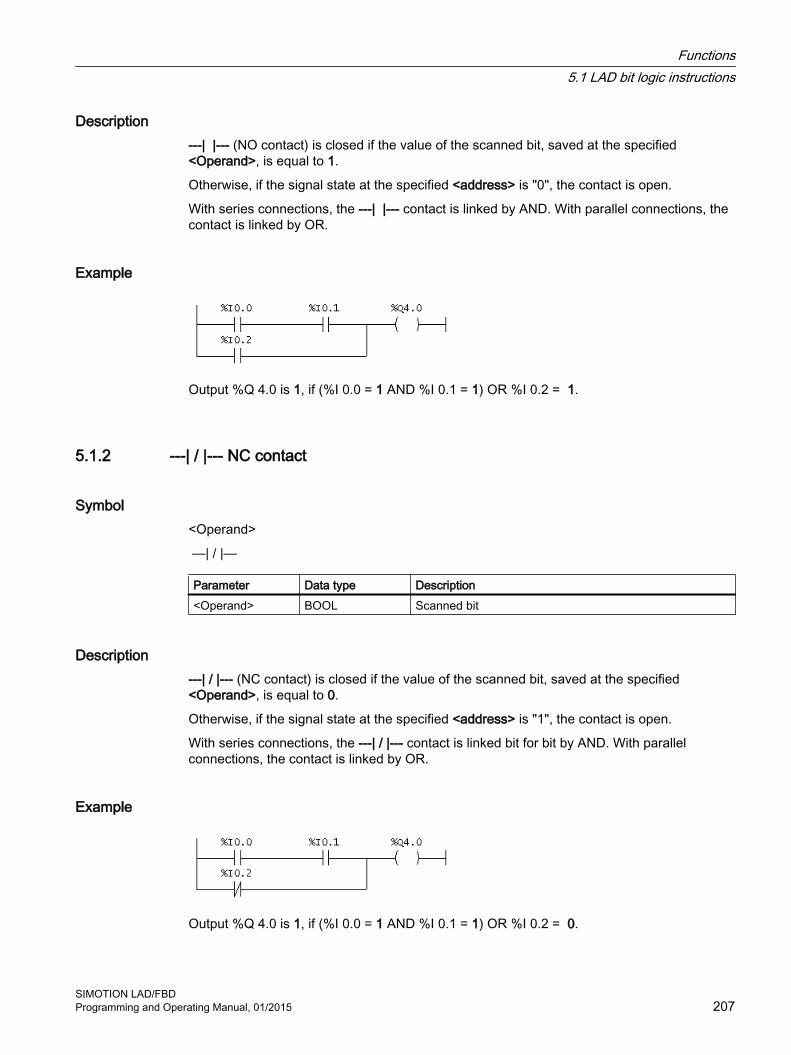
Description---| |--- (NO contact) is closed if the value of the scanned bit, saved at the specified <Operand>, is equal to 1.
Otherwise, if the signal state at the specified <address> is "0", the contact is open.
With series connections, the ---| |--- contact is linked by AND. With parallel connections, the contact is linked by OR.
Example
Output %Q 4.0 is 1, if (%I 0.0 = 1 AND %I 0.1 = 1) OR %I 0.2 = 1.
5.1.2 ---| / |--- NC contact
Symbol <Operand>
—| / |—
Parameter Data type Description<Operand> BOOL Scanned bit
Description ---| / |--- (NC contact) is closed if the value of the scanned bit, saved at the specified <Operand>, is equal to 0.
Otherwise, if the signal state at the specified <address> is "1", the contact is open.
With series connections, the ---| / |--- contact is linked bit for bit by AND. With parallel connections, the contact is linked by OR.
Example
Output %Q 4.0 is 1, if (%I 0.0 = 1 AND %I 0.1 = 1) OR %I 0.2 = 0.
Functions5.1 LAD bit logic instructions
SIMOTION LAD/FBDProgramming and Operating Manual, 01/2015 207
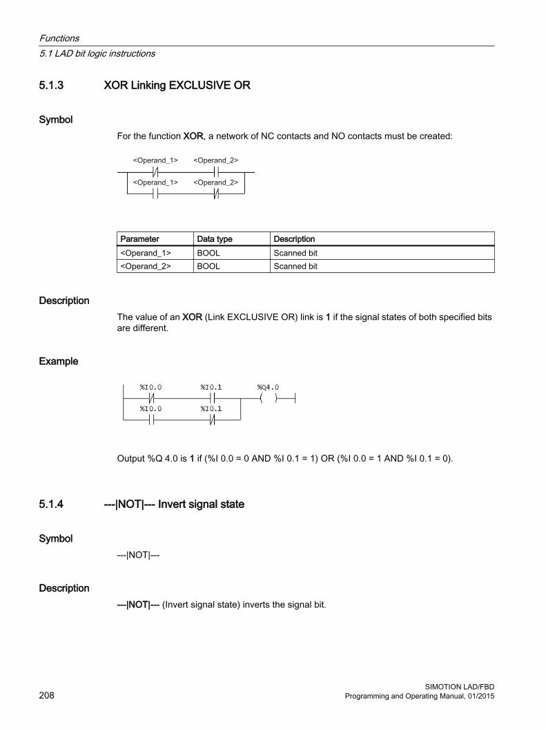
5.1.3 XOR Linking EXCLUSIVE OR
Symbol For the function XOR, a network of NC contacts and NO contacts must be created:
Parameter Data type Description<Operand_1> BOOL Scanned bit<Operand_2> BOOL Scanned bit
DescriptionThe value of an XOR (Link EXCLUSIVE OR) link is 1 if the signal states of both specified bits are different.
Example
Output %Q 4.0 is 1 if (%I 0.0 = 0 AND %I 0.1 = 1) OR (%I 0.0 = 1 AND %I 0.1 = 0).
5.1.4 ---|NOT|--- Invert signal state
Symbol ---|NOT|---
Description ---|NOT|--- (Invert signal state) inverts the signal bit.
Functions5.1 LAD bit logic instructions
SIMOTION LAD/FBD208 Programming and Operating Manual, 01/2015
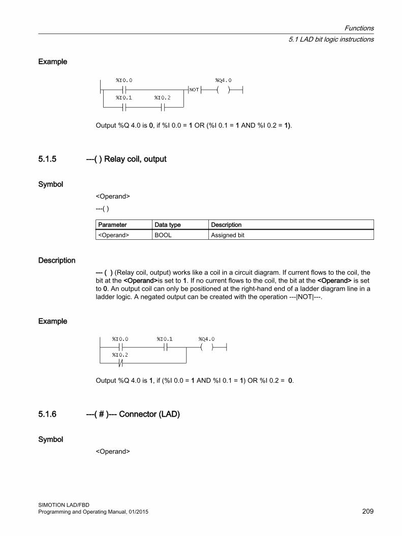
Example
Output %Q 4.0 is 0, if %I 0.0 = 1 OR (%I 0.1 = 1 AND %I 0.2 = 1).
5.1.5 ---( ) Relay coil, output
Symbol <Operand>
---( )
Parameter Data type Description<Operand> BOOL Assigned bit
Description--- ( ) (Relay coil, output) works like a coil in a circuit diagram. If current flows to the coil, the bit at the <Operand>is set to 1. If no current flows to the coil, the bit at the <Operand> is set to 0. An output coil can only be positioned at the right-hand end of a ladder diagram line in a ladder logic. A negated output can be created with the operation ---|NOT|---.
Example
Output %Q 4.0 is 1, if (%I 0.0 = 1 AND %I 0.1 = 1) OR %I 0.2 = 0.
5.1.6 ---( # )--- Connector (LAD)
Symbol <Operand>
Functions5.1 LAD bit logic instructions
SIMOTION LAD/FBDProgramming and Operating Manual, 01/2015 209

---( # )---
Parameters Data type Description<Operand> BOOL Assigned bit
Description ---( # )--- (Connector) is an interposed element with assignment function which saves the current signal state of the signal flow at a specified <Operand>. This assignment element saves the bit logic of the last opened branch in front of the assignment element. If connected in series with other elements, the ---( # )---operation is pasted in as a contact. The ---( # )--- element can never be connected to the conductor bar, nor positioned directly behind a branch, nor used as the end of a branch. A negated element ---( # )--- can be created with the element ---|NOT|--- (Invert signal state).
Example
5.1.7 ---( R ) Reset output (LAD)
Symbol <Operand>
---( R )
Parameter Data type Description<Operand> BOOL Assigned bit
Description ---( R ) (Reset output) is executed only if the signal state of the previous operations is 1 (signal flow at the coil). If the signal state is 1, the specified <Operand> of the element is set to 0.
A signal state of 0 (no signal flow at the coil) has no effect, so that the signal state of the operand of the specified element is not changed.
Functions5.1 LAD bit logic instructions
SIMOTION LAD/FBD210 Programming and Operating Manual, 01/2015

Example
Output %Q 4.0 is set to 0, if (%I 0.0 = 1 AND %I 0.1 = 1) OR %I 0.2 = 0.
If the signal state is 0, the signal state of %Q 4.0 remains the same.
5.1.8 ---( S ) Set output (LAD)
Symbol <Operand>
---( S )
Parameter Data type Description<Operand> BOOL Set bit
Description ---( S) (Set output) is executed only if the signal state of the previous operations is 1 (signal flow at the coil). If the signal state is 1, the specified <Operand> of the element is set to 1.
A signal state = 0 has no effect, so that the current signal state of the specified element's operand is not changed.
Example
Output %Q 4.0 is set to 1, if %I 0.0 = 1 AND %I 0.1 = 1) OR %I 0.2 = 0.
If the signal state is 0, the signal state of %Q 4.0 remains the same.
Functions5.1 LAD bit logic instructions
SIMOTION LAD/FBDProgramming and Operating Manual, 01/2015 211

5.1.9 RS Prioritize reset flipflop
Symbol
Parameters Data type Description<Operand> RS Instance variable of FB type RSS BOOL SetR1 BOOL ResetQ1 BOOL Signal state of <address>
DescriptionRS (Prioritize reset flip-flop) is reset if the state at input R1 is 1. For the state at output Q1, this means:
● Q1 = 0, if input R1 has state 1 irrespective of the state at the S input.
● Q1 = 1, if input S has state 1 and input R1 has state 0.
● Q1 unchanged, if both R1 and S inputs have state 0.
Example
VAR1 is declared as a variable of data type RS and is used as instance of the function block. The I/O addresses %I 0.0 and %I 0.0 (process image of the inputs) are connected to the inputs S and R1 of the function block. Output Q1 of the function block is connected to I/O address %Q 4.0 (process image of the outputs).
The following applies for the signal state at output address %Q 4.0 depending of the signal state at input addresses %I 0.0 and %I0.1:
● %I 0.0 = 1 and %I 0.1 = 1 ⇒ %Q 4.0 = 0.
● %I 0.0 = 1 and %I 0.1 = 0 ⇒ %Q 4.0 = 1.
● %I 0.0 = 0 and %I 0.1 = 1 ⇒ %Q 4.0 = 0.
● %I 0.0 = 0 and %I 0.1 = 0 ⇒ %Q 4.0 remains the same.
Functions5.1 LAD bit logic instructions
SIMOTION LAD/FBD212 Programming and Operating Manual, 01/2015

5.1.10 SR Prioritize set flipflop
Symbol
Parameters Data type Description<Operand> SR Instance variable from FB type SRS1 BOOL SetR BOOL ResetQ1 BOOL Signal state of <address>
DescriptionSR (Prioritize set flip-flop) is set if input S1 has state 1. For the state at output Q1, this means:
● Q1 = 1, if input S1 has state 1 irrespective of the state at the R input.
● Q1 = 0, if input R has state 1 and input S1 has state 0.
● Q1 unchanged, if both R and S1 inputs have state 0.
Example
VAR1 is declared as a variable of data type SR and is used as instance of the function block. The I/O addresses %I 0.0 and %I 0.0 (process image of the inputs) are connected to the inputs S1 and R of the function block. Output Q1 of the function block is connected to I/O address %Q 4.0 (process image of the outputs).
The following applies for the signal state at output address %Q 4.0 depending of the signal state at input addresses %I 0.0 and %I0.1:
● %I 0.0 = 1 and %I 0.1 = 1 ⇒ %Q 4.0 = 1.
● %I 0.0 = 1 and %I 0.1 = 0 ⇒ %Q 4.0 = 1.
● %I 0.0 = 0 and %I 0.1 = 1 ⇒ %Q 4.0 = 0.
● %I 0.0 = 0 and %I 0.1 = 0 ⇒ %Q 4.0 remains the same.
Functions5.1 LAD bit logic instructions
SIMOTION LAD/FBDProgramming and Operating Manual, 01/2015 213

5.1.11 --( N )-- Scan edge 1 -> 0 (LAD)
Symbol <Operand>
---( N )---
Parameters Data type Description<Operand> BOOL N connector bit, saves the previous signal state
Description---( N )--- (Scan edge 1 -> 0) recognizes a signal state change in the operand from 1 to 0 and displays this after the operation with signal state = 1. The current signal state is compared to the signal state of the operand, the N connector. If the signal state of the operand is 1 and the signal state before the operation is 0, then the signal after the operation is 1 (pulse), in all other cases 0. The signal before the operation is saved in the operand.
Example
The N-connector saves the signal state of the result of the entire bit logic.
If the signal state changes from 1 to 0 the jump to the CAS1 jump label is performed.
5.1.12 --( P )-- Scan edge 0 -> 1 (LAD)
Symbol <Operand>
---( P )---
Parameters Data type Description<Operand> BOOL P connector bit, saves the previous signal state
Functions5.1 LAD bit logic instructions
SIMOTION LAD/FBD214 Programming and Operating Manual, 01/2015

Description ---( P )--- (Scan edge 0 -> 1) recognizes a signal state change in the operand from 0 to 1 and displays this after the operation with signal state = 1. The current signal state is compared to the signal state of the operand, the P connector. If the signal state of the operand is 0 and the signal state before the operation is 1, then the signal after the operation is 1 (pulse), in all other cases 0. The signal before the operation is saved in the operand.
Example
The P-connector saves the signal state of the result of the entire bit logic. If the signal state changes from 0 to 1 the jump to the CAS1 jump label is performed.
5.1.13 NEG edge detection (falling)
Symbol
Parameters Data type Description<Operand1> BOOL Scanned signal<Operand2> BOOL Connector bit, saves the previous signal state from <Oper‐
and1>Q BOOL Signal change detection
DescriptionNEG (edge detection) compares the signal state of <Operand1> with the signal state of the previous scan, which is saved in <Operand2>. If the current state of the signal is 0 and the previous state was 1 (detection of a falling edge), output Q is 1 after this function, in all other cases 0.
Functions5.1 LAD bit logic instructions
SIMOTION LAD/FBDProgramming and Operating Manual, 01/2015 215

Example
Output %Q 4.0 is 1 if:
(The state at %I 0.0 AND at %I 0.1 AND at %I 0.2 = 1) AND VAR1 has a falling edge AND the state at %I 0.4 = 1.
5.1.14 POS edge detection (rising)
Symbol
Parameters Data type Description<Operand1> BOOL Scanned signal<Operand2> BOOL Connector bit, saves the previous signal state from <Oper‐
and1>Q BOOL Signal change detection
DescriptionPOS (edge detection) compares the signal state of <Operand1> with the signal state of the previous scan, which is saved in <Operand2>. If the current state of the signal is 1 and the previous state was 0 (detection of a rising edge), output Q is 1 after this operation, in all other cases 0.
Example
Functions5.1 LAD bit logic instructions
SIMOTION LAD/FBD216 Programming and Operating Manual, 01/2015

Output %Q 4.0 is 1 if:
(The state at %I 0.0 AND at %I 0.1 AND at %I 0.2 = 1) AND VAR1 has a rising edge AND the state at %I 0.4 = 1.
5.1.15 Open branchParallel branches are opened downward.
Parallel branches are always opened behind the selected LAD element.
ProcedureTo open a parallel branch downward, follow these steps:
1. Use the cursor to select the position where the branch is to be opened.
2. Click the button (shortcut Shift+F8) on the LAD editor toolbar.The branch is opened behind the selected element.
5.1.16 Close branchParallel branches are closed upward.
Parallel branches are always closed behind the selected LAD element.
Functions5.1 LAD bit logic instructions
SIMOTION LAD/FBDProgramming and Operating Manual, 01/2015 217

ProcedureTo close a parallel branch upward, follow these steps:
1. Use the cursor to select the position where the branch is to be closed.
2. Click the button (shortcut Shift+F9) on the LAD editor toolbar.The branch is closed behind the selected element.
Or:
1. Using the cursor, select the parallel branch to be closed.
2. Holding down the left mouse button, move the selected branch to the position at which it is to be closed.
3. Release the left mouse button.The branch is closed at the selected position.
Functions5.1 LAD bit logic instructions
SIMOTION LAD/FBD218 Programming and Operating Manual, 01/2015
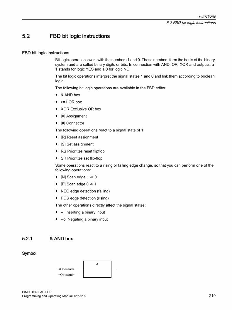
5.2 FBD bit logic instructions
FBD bit logic instructions Bit logic operations work with the numbers 1 and 0. These numbers form the basis of the binary system and are called binary digits or bits. In connection with AND, OR, XOR and outputs, a 1 stands for logic YES and a 0 for logic NO.
The bit logic operations interpret the signal states 1 and 0 and link them according to boolean logic.
The following bit logic operations are available in the FBD editor:
● & AND box
● >=1 OR box
● XOR Exclusive OR box
● [=] Assignment
● [#] Connector
The following operations react to a signal state of 1:
● [R] Reset assignment
● [S] Set assignment
● RS Prioritize reset flipflop
● SR Prioritize set flip-flop
Some operations react to a rising or falling edge change, so that you can perform one of the following operations:
● [N] Scan edge 1 -> 0
● [P] Scan edge 0 -> 1
● NEG edge detection (falling)
● POS edge detection (rising)
The other operations directly affect the signal states:
● --| Inserting a binary input
● --o| Negating a binary input
5.2.1 & AND box
Symbol
Functions5.2 FBD bit logic instructions
SIMOTION LAD/FBDProgramming and Operating Manual, 01/2015 219

Parameters Data type Description<Operand> BOOL Scanned bit
DescriptionWith the AND operation, you can scan the signal states of two or more specified operands at the inputs of an AND box. If the signal status of all operands is 1, the condition is fulfilled and the result of the operation is 1. If the signal status of one operand is 0, the condition is not fulfilled and the operation returns a result of 0.
Example
Output %Q 4.0 is set when the signal state at input %I 1.0 AND %I 1.1 is 1.
5.2.2 >=1 OR box
Symbol
Parameters Data type Description<Operand> BOOL Scanned bit
DescriptionWith the OR operation, you can scan the signal states of two or more specified operands at the inputs of an OR box. If the signal status of one of the operands is 1, the condition is fulfilled and the result of the operation is 1. If the signal status of all operands is 0, the condition is not fulfilled and the operation returns a result of 0.
Functions5.2 FBD bit logic instructions
SIMOTION LAD/FBD220 Programming and Operating Manual, 01/2015

Example
Output %Q 4.0 is set when the signal state at input %I 1.0 OR %I 1.1 is 1.
5.2.3 XOR EXCLUSIVE OR box
Symbol
Parameters Data type Description<Operand> BOOL Scanned bit
DescriptionIn an EXCLUSIVE OR box, the signal state is 1 if the signal state of one of the two specified operands is 1.
Example
At output %Q 4.0, the signal state is 1 if the signal state is 1 either EXCLUSIVELY at input %I 0.0 OR at input %I 0.1.
5.2.4 --| Inserting a binary input
Symbol <Operand>
Functions5.2 FBD bit logic instructions
SIMOTION LAD/FBDProgramming and Operating Manual, 01/2015 221
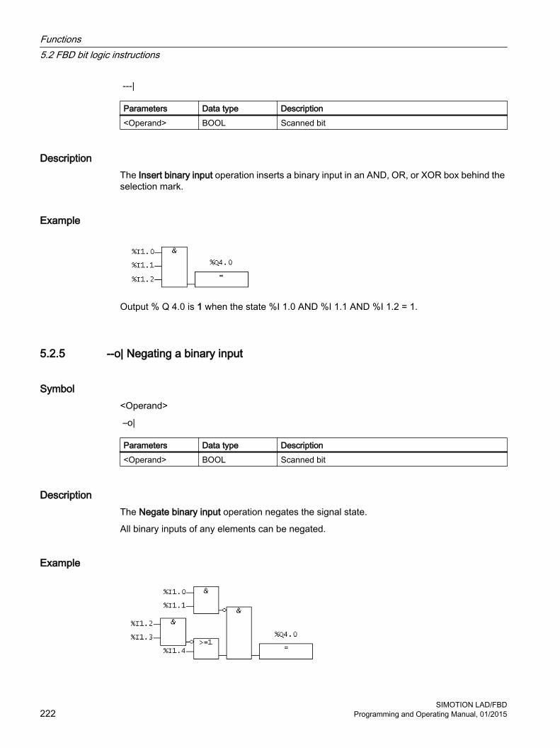
---|
Parameters Data type Description<Operand> BOOL Scanned bit
DescriptionThe Insert binary input operation inserts a binary input in an AND, OR, or XOR box behind the selection mark.
Example
Output % Q 4.0 is 1 when the state %I 1.0 AND %I 1.1 AND %I 1.2 = 1.
5.2.5 --o| Negating a binary input
Symbol <Operand>
–o|
Parameters Data type Description<Operand> BOOL Scanned bit
DescriptionThe Negate binary input operation negates the signal state.
All binary inputs of any elements can be negated.
Example
Functions5.2 FBD bit logic instructions
SIMOTION LAD/FBD222 Programming and Operating Manual, 01/2015
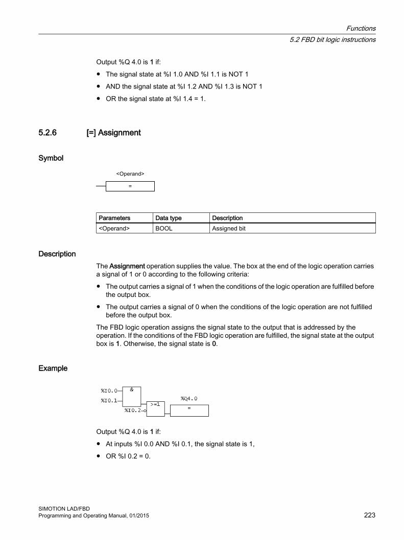
Output %Q 4.0 is 1 if:
● The signal state at %I 1.0 AND %I 1.1 is NOT 1
● AND the signal state at %I 1.2 AND %I 1.3 is NOT 1
● OR the signal state at %I 1.4 = 1.
5.2.6 [=] Assignment
Symbol
Parameters Data type Description<Operand> BOOL Assigned bit
DescriptionThe Assignment operation supplies the value. The box at the end of the logic operation carries a signal of 1 or 0 according to the following criteria:
● The output carries a signal of 1 when the conditions of the logic operation are fulfilled before the output box.
● The output carries a signal of 0 when the conditions of the logic operation are not fulfilled before the output box.
The FBD logic operation assigns the signal state to the output that is addressed by the operation. If the conditions of the FBD logic operation are fulfilled, the signal state at the output box is 1. Otherwise, the signal state is 0.
Example
Output %Q 4.0 is 1 if:
● At inputs %I 0.0 AND %I 0.1, the signal state is 1,
● OR %I 0.2 = 0.
Functions5.2 FBD bit logic instructions
SIMOTION LAD/FBDProgramming and Operating Manual, 01/2015 223

5.2.7 [#] Connector (FBD)
Symbol
Parameters Data type Description<Operand1> BOOL Assigned bit
Description The Connector operation is an intermediate assignment element that stores the signal state. Specifically, this assignment element saves the bit logic of the last opened branch in front of the assignment element.
Example
Connectors store the following logic operation results:
VAR4 saves the negated signal state of
%I1.0
%I1.1
VAR1 saves the negated signal state of
%I1.2
%I1.3
VAR2 saves the negated signal state of %I 1.4.
VAR3 saves the negated signal state of the entire bit logic operation.
Functions5.2 FBD bit logic instructions
SIMOTION LAD/FBD224 Programming and Operating Manual, 01/2015
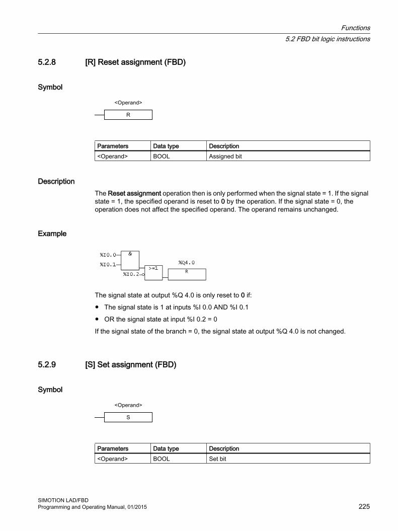
5.2.8 [R] Reset assignment (FBD)
Symbol
Parameters Data type Description<Operand> BOOL Assigned bit
Description The Reset assignment operation then is only performed when the signal state = 1. If the signal state = 1, the specified operand is reset to 0 by the operation. If the signal state = 0, the operation does not affect the specified operand. The operand remains unchanged.
Example
The signal state at output %Q 4.0 is only reset to 0 if:
● The signal state is 1 at inputs %I 0.0 AND %I 0.1
● OR the signal state at input %I 0.2 = 0
If the signal state of the branch = 0, the signal state at output %Q 4.0 is not changed.
5.2.9 [S] Set assignment (FBD)
Symbol
Parameters Data type Description<Operand> BOOL Set bit
Functions5.2 FBD bit logic instructions
SIMOTION LAD/FBDProgramming and Operating Manual, 01/2015 225

Description The Set assignment operation is only performed when the signal state = 1. If the signal state = 1, the specified operand is reset to 1 by the operation. If the signal state = 0, the operation does not affect the specified operand. The operand remains unchanged.
Example
The signal state at output %Q 4.0 is only reset to 1 if:
● The signal state is 1 at inputs %I 0.0 AND %I 0.1
● OR the signal state at input %I 0.2 = 0
If the signal state of the branch = 0, the signal state of %Q 4.0 is not changed.
5.2.10 RS Prioritize reset flipflop
Symbol
Parameters Data type Description<Operand> RS Instance variable of FB type RSS BOOL Enable setR1 BOOL Enable resetQ1 BOOL Signal state of <address>
DescriptionThe Prioritize reset flipflop operation only performs operations such as Set assignment (S) or Reset assignment (R1) if the signal state = 1. A signal state of 0 has no effect on these operations; the operand specified in the operation is not changed.
Prioritize reset flipflop is reset when the signal state at input R1 = 1 and the signal state at input S = 0. The flipflop is set when input R1 = 0 and input S = 1. If the signal state at both inputs is 1, the flipflop is reset.
Functions5.2 FBD bit logic instructions
SIMOTION LAD/FBD226 Programming and Operating Manual, 01/2015

Example
If the state at input %I 0.0 = 1 and at input %I 0.1 = 0, the variable VAR1 is set and output %Q 4.0 is 1. Otherwise, if the signal state at input %I 0.0 = 0 and the signal state at input %I 0.1 = 1, the variable VAR1 is reset and %Q 4.0 is 0.
If both signal states are 0, nothing is changed. If both signal states are 1, the reset operation has priority. VAR1 is reset and %Q 4.0 is 0.
5.2.11 SR Prioritize set flipflop
Symbol
Parameters Data type Description<Operand> SR Instance variable from FB type SRS1 BOOL Enable setR BOOL Enable resetQ1 BOOL Signal state of <address>
DescriptionThe Prioritize set flipflop operation only performs operations such as Set (S1) or Reset (R) if the signal state = 1. A signal state of 0 has no effect on these operations; the operand specified in the operation is not changed.
Prioritize set flipflop is set when the signal state at input S1 = 1 and the signal state at input R = 0. The flipflop is reset when input S1 = 0 and input R = 1. If the signal state at both inputs is 1, the flipflop is set.
Functions5.2 FBD bit logic instructions
SIMOTION LAD/FBDProgramming and Operating Manual, 01/2015 227

Example
If the state at input %I 0.0 = 1 and at input %I 0.1 = 0, the variable VAR1 is set and output %Q 4.0 is 1. Otherwise, if the signal state at input %I 0.0 = 0 and the signal state at input %I 0.1 = 1, the variable VAR1 is reset and %Q 4.0 is 0.
If both signal states are 0, nothing is changed. If both signal states are 1, the set operation has priority. VAR1 is set and %Q 4.0 is 1.
5.2.12 [N] Scan edge 1 -> 0 (FBD)
Symbol
Parameters Data type Description<Operand> BOOL N connector bit, saves the previous signal state
DescriptionThe Scan edge 1 -> 0 recognizes a signal state change in the specified operands from 1 to 0 (falling edge) and displays this after the operation with signal state = 1. The current signal state is compared to the signal state of the operand, the edge variable. If the signal state of the operand is 1 and the signal state before the operation is 0, then the signal after the operation is 1 (pulse), in all other cases 0. The signal state before the operation is saved in the operand.
Functions5.2 FBD bit logic instructions
SIMOTION LAD/FBD228 Programming and Operating Manual, 01/2015

Example
The VAR4 variable saves the signal state.
5.2.13 [P] Scan edge 0 -> 1 (FBD)
Symbol
Parameters Data type Description<Operand> BOOL P connector bit, saves the previous signal state
Description The Scan edge 0 -> 1 recognizes a signal state change in the specified operands from 0 to1 (rising edge) and displays this after the operation with signal state = 1. The current signal state is compared to the signal state of the operand, the edge variable. If the signal state of the operand is 0 and the signal state before the operation is 1, then the signal state after the operation is 1, in all other cases 0. The signal state before the operation is saved in the operand.
Example
Functions5.2 FBD bit logic instructions
SIMOTION LAD/FBDProgramming and Operating Manual, 01/2015 229

The VAR1 variable saves the signal state.
5.2.14 NEG edge detection (falling)
Symbol
Parameters Data type Description<Operand1> BOOL Scanned signalM_BIT BOOL The M-BIT operand indicates the variable in which the pre‐
vious signal state of NEG is saved.Q BOOL Signal change detection
DescriptionThe Edge detection (falling) operation compares the signal state of <Operand1> with the signal state of the previous scan, which is saved in M_BIT. If a change has occurred from 1 to 0, then output Q = 1, in all other cases 0.
Example
Output %Q 4.0 is 1 if:
● Input %I 0.3 has a falling edge
● AND the signal state at input %I 0.4 = 1.
Functions5.2 FBD bit logic instructions
SIMOTION LAD/FBD230 Programming and Operating Manual, 01/2015

5.2.15 POS edge detection (rising)
Symbol
Parameters Data type Description<Operand1> BOOL Scanned signalM_BIT BOOL The M-BIT operand indicates the variable in which the pre‐
vious signal state of POS is saved.Q BOOL Signal change detection
DescriptionThe Edge detection (rising) operation compares the signal state of <Operand1> with the signal state of the previous scan, which is saved in M_BIT. If a change has occurred from 0 to 1, then output Q = 1, in all other cases 0.
Example
Output %Q 4.0 is 1 if:
● Input %I 0.3 has a rising edge
● AND the signal state at input %I 0.4 = 1.
Functions5.2 FBD bit logic instructions
SIMOTION LAD/FBDProgramming and Operating Manual, 01/2015 231

5.3 Relational operators
5.3.1 Overview of comparison operations
Description The inputs IN1 and IN2 are compared using the following comparison methods:
= IN1 is equal to IN2<> IN1 is not equal to IN2> IN1 is greater than IN2< IN1 is less than IN2>= IN1 is greater than or equal to IN2<= IN1 is less than or equal to IN2
The following comparison operation is available:
● CMP comparator
5.3.2 CMP Compare numbers
Icons
Table 5-1 Parameters for CMP <, CMP > CMP >=, CMP <=
Parameter Data type DescriptionBox output BOOL Result of the comparison,
processing is only continued if the signal state at the box input = 1.
IN1 ANY_NUM1
ANY_BITDATETIME_OF_DAY (TOD)DATE_AND_TIME (DT)TIMESTRING2
First comparison value
Functions5.3 Relational operators
SIMOTION LAD/FBD232 Programming and Operating Manual, 01/2015

Parameter Data type DescriptionIN2 ANY_NUM1
ANY_BITDATETIME_OF_DAY (TOD)DATE_AND_TIME (DT)TIMESTRING2
Second comparison value
The first and second comparison values must be of the same data type, e.g. ANY_NUM and ANY_NUM, DATE and DATE, STRING and STRING.1 It must be possible to convert both comparison values into the most powerful data type by means of implicit conversion.2 Variables of the STRING data type can be compared irrespective of the declared length of the string.
Table 5-2 Parameter for CMP =, CMP <>
Parameter Data type DescriptionBox output BOOL Result of the comparison,
processing is only continued if the signal state at the box input = 1.
IN1 ANY_NUM1
ANY_BITDATETIME_OF_DAY (TOD)DATE_AND_TIME (DT)TIMESTRING2
Enumeration3
Array3
Structure3
STRUCTTASKIDSTRUCTALARMIDANYOBJECT
First comparison value
IN2 ANY_NUM1
ANY_BITDATETIME_OF_DAY (TOD)DATE_AND_TIME (DT)TIMESTRING2
Enumeration3
Array3
Structure3
STRUCTTASKIDSTRUCTALARMIDANYOBJECT
Second comparison value
The first and second comparison values must be of the same data type, e.g. ANY_NUM and ANY_NUM, DATE and DATE, STRING and STRING. 1 It must be possible to convert both comparison values into the most powerful data type by means of implicit conversion.2 Variables of the STRING data type can be compared irrespective of the declared length of the string.3 The data type specifications (see the SIMOTION ST Programming and Operating Manual) must be identical for both comparison values.
Functions5.3 Relational operators
SIMOTION LAD/FBDProgramming and Operating Manual, 01/2015 233

DescriptionCMP (Compare numbers) can be used like a normal contact. The box can be used at the positions where a normal contact can also be positioned. IN1 and IN2 are compared with the comparison method selected by you.
If the comparison is true, then the value of the operation is 1. The value of the whole ladder diagram line is linked by AND if the comparison element is connected in series or by OR if the box is connected in parallel.
Example
Representation in the LAD editor
Representation in the FBD editor
%Q 4.0 is set when:
● VAR1 >= VAR2
● AND the signal state at input %I 0.0 is (1).AND the signal state at input %I 0.1 is (1).AND the signal state at input %I 0.2 is (1).
Functions5.3 Relational operators
SIMOTION LAD/FBD234 Programming and Operating Manual, 01/2015

5.4 Conversion instructions
5.4.1 TRUNC Generate integer
Symbol
Parameters Data type DescriptionEN BOOL Enable inputENO BOOL Enable outputIN ANY_REAL Number which is to be convertedOUT ANY_INT Integral part of the value from IN
DescriptionTRUNC (generate integer) reads the contents of the IN parameter as a floating-point number and converts this value to an integer (32-bit). The result is the integral part of the floating-point number which is output by the OUT parameter.
Example
Representation in the LAD editor
Representation in the FBD editor
If %I 0.0 = 1, the contents of VAR1 are read as a floating-point number and converted to an integer (32-bit). The result is the integral part of the floating-point number which is saved in VAR2. Output %Q 4.0 is 1 if an overflow occurs or the statement is not processed (%I 0.0 = 0).
Functions5.4 Conversion instructions
SIMOTION LAD/FBDProgramming and Operating Manual, 01/2015 235

5.4.2 Generating numeric data types and bit data types
Symbol e.g. BOOL_TO_TYPE
DescriptionYou can carry out the explicit data type conversion with the standard functions listed in the tables below.
● Input parametersEach function for the conversion of a data type has exactly one input parameter.
● Function valueThe function value is always the return value of the function. The table shows the rules with which a data type can be converted.
● NamingBecause the data types of the input parameter and the function value come from the respective function name, they are not listed specially in the table "Functions for conversion of numerical data types and bit data types": E.g. with function BOOL_TO_BYTE, the data type of the input parameter is BOOL, the data type of the function value BYTE.
Table 5-3 Functions for conversion of numerical data types and bit data types
Function name Conversion rule Implicitokay
BOOL_TO_BYTE Accept as least significant bit and fill the rest with 0. yesBYTE_TO_BOOL Accept the least significant bit. noBYTE_TO_SINT Accept bit string as SINT value. noBYTE_TO_USINT Accept bit string as USINT value. noBYTE_TO_WORD Accept least significant bit and fill the rest with 0. yes
Table 5-4 Functions for conversion of numerical data types and bit data types
Function name Conversion rule Implicitokay
DINT_TO_DWORD Accept value as bit string. noDINT_TO_INT Cut off two most significant bytes. noDINT_TO_LREAL Accept value. yesDINT_TO_REAL Accept value (accuracy may be lost). noDINT_TO_UDINT Accept value as bit string. no
Functions5.4 Conversion instructions
SIMOTION LAD/FBD236 Programming and Operating Manual, 01/2015

Function name Conversion rule Implicitokay
DINT_TO_UINT Cut off two most significant bytes. noDINT_TO_WORD Cut off two most significant bytes. no
Table 5-5 Functions for conversion of numerical data types and bit data types
Function name Conversion rule Implicitokay
DWORD_TO_DINT Accept bit string as DINT value. noDWORD_TO_INT Accept the two least significant bytes as INT value. noDWORD_TO_REAL Accept bit string as REAL value (validity check of the RE‐
AL number is not carried out!).no
DWORD_TO_UDINT Accept bit string as UDINT value. noDWORD_TO_UINT Accept the two least significant bytes as UINT value. noDWORD_TO_WORD Accept the two least significant bytes of the bit string. no
Table 5-6 Functions for conversion of numerical data types and bit data types
Function name Conversion rule Implicitokay
INT_TO_DINT Accept value. yesINT_TO_LREAL Accept value. noINT_TO_REAL Accept value. yesINT_TO_SINT Cut off the most significant byte. noINT_TO_UDINT Accept value as bit string; the two most significant bytes
are filled with the most significant bit of the input parame‐ter.
no
INT_TO_UINT Accept value as bit string. noINT_TO_WORD Accept value as bit string. no
Table 5-7 Functions for conversion of numerical data types and bit data types
Function name Conversion rule Implicitokay
LREAL_TO_DINT Round off to integer part. noLREAL_TO_INT Round off to integer part. noLREAL_TO_REAL Accept value (accuracy may be lost). noLREAL_TO_UDINT Round off to integer part. noLREAL_TO_UINT Round off to integer part. no
Functions5.4 Conversion instructions
SIMOTION LAD/FBDProgramming and Operating Manual, 01/2015 237
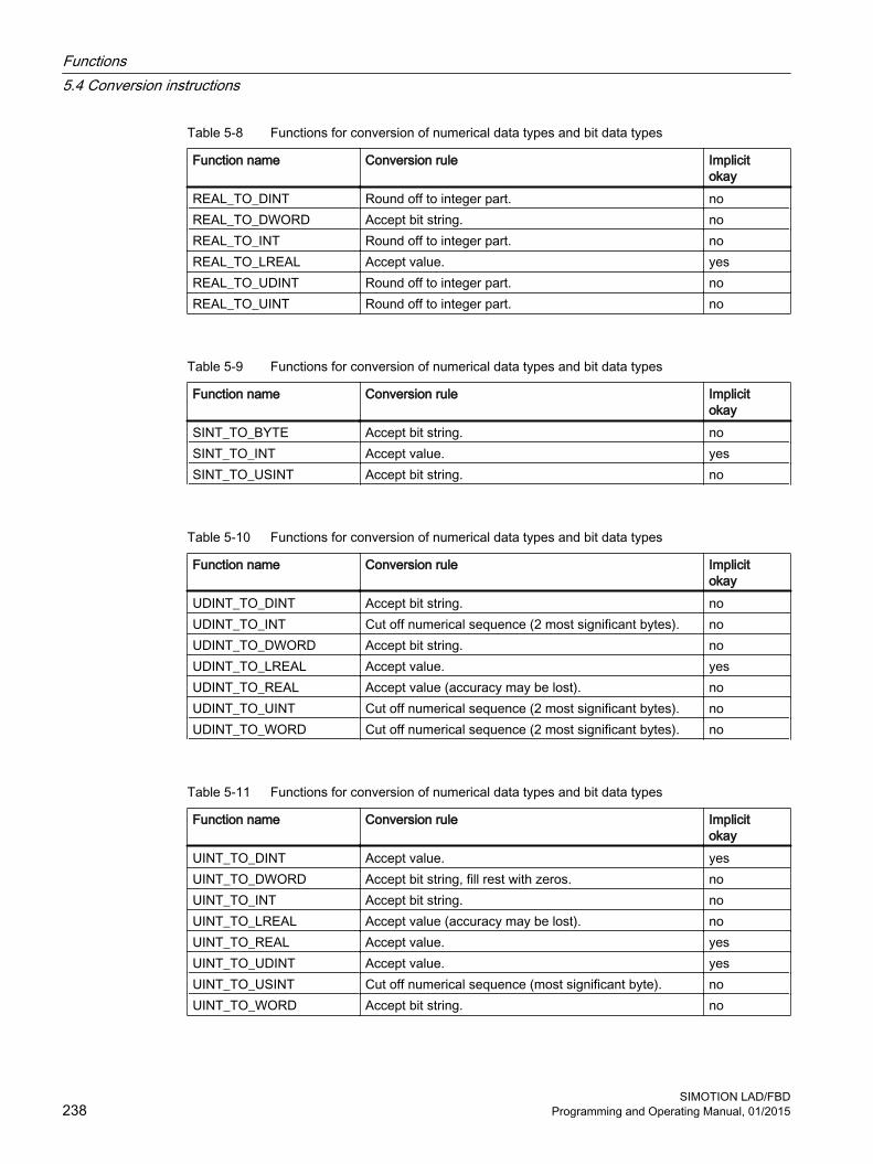
Table 5-8 Functions for conversion of numerical data types and bit data types
Function name Conversion rule Implicitokay
REAL_TO_DINT Round off to integer part. noREAL_TO_DWORD Accept bit string. noREAL_TO_INT Round off to integer part. noREAL_TO_LREAL Accept value. yesREAL_TO_UDINT Round off to integer part. noREAL_TO_UINT Round off to integer part. no
Table 5-9 Functions for conversion of numerical data types and bit data types
Function name Conversion rule Implicitokay
SINT_TO_BYTE Accept bit string. noSINT_TO_INT Accept value. yesSINT_TO_USINT Accept bit string. no
Table 5-10 Functions for conversion of numerical data types and bit data types
Function name Conversion rule Implicitokay
UDINT_TO_DINT Accept bit string. noUDINT_TO_INT Cut off numerical sequence (2 most significant bytes). noUDINT_TO_DWORD Accept bit string. noUDINT_TO_LREAL Accept value. yesUDINT_TO_REAL Accept value (accuracy may be lost). noUDINT_TO_UINT Cut off numerical sequence (2 most significant bytes). noUDINT_TO_WORD Cut off numerical sequence (2 most significant bytes). no
Table 5-11 Functions for conversion of numerical data types and bit data types
Function name Conversion rule Implicitokay
UINT_TO_DINT Accept value. yesUINT_TO_DWORD Accept bit string, fill rest with zeros. noUINT_TO_INT Accept bit string. noUINT_TO_LREAL Accept value (accuracy may be lost). noUINT_TO_REAL Accept value. yesUINT_TO_UDINT Accept value. yesUINT_TO_USINT Cut off numerical sequence (most significant byte). noUINT_TO_WORD Accept bit string. no
Functions5.4 Conversion instructions
SIMOTION LAD/FBD238 Programming and Operating Manual, 01/2015

Table 5-12 Functions for conversion of numerical data types and bit data types
Function name Conversion rule Implicitokay
USINT_TO_BYTE Accept bit string. noUSINT_TO_INT Accept value. yesUSINT_TO_DINT Accept value. noUSINT_TO_SINT Accept bit string. noUSINT_TO_UINT Accept value. yes
Table 5-13 Functions for conversion of numerical data types and bit data types
Function name Conversion rule Implicitokay
WORD_TO_BYTE Cut off most significant byte. noWORD_TO_DINT Accept bit string, fill rest with zeros. noWORD_TO_DWORD Accept the two least significant bytes and fill the rest with
0.yes
WORD_TO_INT Accept bit string and interpret this as an integer. noWORD_TO_UDINT Accept bit string, fill rest with zeros. noWORD_TO_UINT Accept bit string. no
5.4.3 Generating date and time
Symbol
Functions5.4 Conversion instructions
SIMOTION LAD/FBDProgramming and Operating Manual, 01/2015 239

DescriptionThe table below shows the standard functions for date and time data types:
Table 5-14 Standard functions for date and time
Function name
Data type ofinput parameter
Data type of function value
Description
CONCAT 1: DATE 2: TIME_OF_DAY
DATE_AND_TIME Compress DATE and TIME_OF_DAY to DATE_AND_TIME.
DT_TO_TOD DATE_AND_TIME TIME_OF_DAY Accept time of day.DT_TO_DATE DATE_AND_TIME DATE Accept date.
Note
Data type TIME can be converted to numerical data types as follows:
● To data type UDINT: Divide it by a standardization factor of data type TIME.Multiply the reconversion by the same standardization factor.
Functions5.4 Conversion instructions
SIMOTION LAD/FBD240 Programming and Operating Manual, 01/2015

5.5 Edge detectionSystem function block R_TRIG can be used to detect a rising edge; F_TRIG can detect a falling edge. You can use this function, for example, to set up a sequence of your own function blocks.
5.5.1 Detection of rising edge R_TRIG
Symbol
DescriptionIf a rising edge (R_TRIG, Rising Trigger), i.e. a status change from 0 to 1, is present at the input, 1 is applied at the output for the duration of one cycle.
TA Cycle time
Figure 5-1 Mode of operation of R_TRIG (rising edge) function block
Table 5-15 Call parameters for R_TRIG
Identifier Parameter Data type DescriptionCLK Input BOOL Input for edge detectionQ Output BOOL Status of edge
5.5.2 Detection of falling edge F_TRIG
Symbol
Functions5.5 Edge detection
SIMOTION LAD/FBDProgramming and Operating Manual, 01/2015 241

DescriptionWhen a falling edge (F_TRIG, falling trigger), i.e. a status change from 1 to 0, occurs at the input, the output is set to 1 for the duration of one cycle time.
TA Cycle time
Figure 5-2 Mode of operation of F_TRIG (falling edge) function block
Table 5-16 Call parameters for F_TRIG
Identifier Parameter Data type DescriptionCLK Input BOOL Input for edge detectionQ Output BOOL Status of edge
Functions5.5 Edge detection
SIMOTION LAD/FBD242 Programming and Operating Manual, 01/2015

5.6 Counter operations
5.6.1 Overview of counter operationsEvery call-up of the function block and the function should be recorded in a counter.
5.6.2 CTU up counter
Symbol
DescriptionThe CTU counter allows you to perform upward counting operations:
● If the input is R = TRUE when the FB is called up, then the CV output is reset to 0.
● If the CU input changes from FALSE to TRUE (0 to 1) when the FB is called (positive edge), then the CV output is incremented by 1.
● Output Q specifies whether CV is greater than or equal to comparison value PV.
The CV and PV parameters are both INT data types, which means that the maximum counter reading possible is 32767 ( = 16#7FFF).
Table 5-17 Parameters for CTU
Identifier Parameter Data type DescriptionCU Input BOOL Count up if value changes from FALSE to
TRUE (positive edge)
R Input BOOL Reset the counter to 0PV Input INT Comparison valueQ Output BOOL Status of counter (CV >= PV)CV Output INT Counter value
Functions5.6 Counter operations
SIMOTION LAD/FBDProgramming and Operating Manual, 01/2015 243

5.6.3 CTU_DINT up counter
Symbol
DescriptionThe method of operation is the same as for the CTU incrementer except for the following:
The CV and PV parameters are both DINT data types, which means that the maximum counter reading possible is 2147483647 ( = 16#7FFF_FFFF).
Table 5-18 Parameters for CTU_DINT
Identifier Parameter Data type DescriptionCU Input BOOL Count up if value changes from FALSE to
TRUE (positive edge)
R Input BOOL Reset the counter to 0PV Input DINT Comparison valueQ Output BOOL Status of counter (CV >= PV)CV Output DINT Counter value
5.6.4 CTU_UDINT up counter
Symbol
Functions5.6 Counter operations
SIMOTION LAD/FBD244 Programming and Operating Manual, 01/2015

DescriptionThe method of operation is the same as for the CTU incrementer except for the following:
The CV and PV parameters are both UDINT data types, which means that the maximum counter reading possible is 4294967295 ( =16# FFFF_FFFF).
Table 5-19 Parameters for CTU_UDINT
Identifier Parameter Data type DescriptionCU Input BOOL Count up if value changes from FALSE to
TRUE (positive edge)R Input BOOL Reset the counter to 0PV Input UDINT Comparison valueQ Output BOOL Status of counter (CV >= PV)CV Output UDINT Counter value
5.6.5 CTD down counter
Symbol
DescriptionThe CTD counter allows you to perform downward counting operations.
● If the LD input = TRUE when the FB is called, then the CV output is reset to start value PV.
● If the CD input changes from FALSE to TRUE (0 to 1) when the FB is called (positive edge), then the CV output is decremented by 1.
● Output Q specifies whether CV is less than or equal to 0.
Functions5.6 Counter operations
SIMOTION LAD/FBDProgramming and Operating Manual, 01/2015 245

The CV and PV parameters are both INT data types, which means that the minimum counter reading possible is -32,768 ( = 16#8000).
Table 5-20 Parameters for CTD
Identifier Parameter Data type DescriptionCD Input BOOL Count down if value changes from FALSE to
TRUE (positive edge)
LD Input BOOL Reset the counter to start valuePV Input INT Start value of counterQ Output BOOL Status of counter (CV <= 0)CV Output INT Counter value
5.6.6 CTD_DINT down counter
Symbol
DescriptionThe method of operation is the same as for the CTD up counter except for the following:
The CV and PV parameters are both DINT data types, which means that the minimum counter reading possible is -2147483648 ( = 16#8000_0000).
Table 5-21 Parameters for CTD_DINT
Identifier Parameter Data type DescriptionCD Input BOOL Count down if value changes from FALSE to
TRUE (positive edge)
LD Input BOOL Reset the counter to start valuePV Input DINT Start value of counterQ Output BOOL Status of counter (CV <= 0)CV Output DINT Counter value
Functions5.6 Counter operations
SIMOTION LAD/FBD246 Programming and Operating Manual, 01/2015

5.6.7 CTD_UDINT down counter
Symbol
DescriptionThe method of operation is the same as for the CTD up counter except for the following:
The CV and PV parameters are both UDINT data types, which means that the minimum counter value possible is 0.
Table 5-22 Parameters for CTD_DINT
Identifier Parameter Data type DescriptionCD Input BOOL Count down if value changes from FALSE to
TRUE (positive edge)
LD Input BOOL Reset the counter to start valuePV Input UDINT Start value of counterQ Output BOOL Status of counter (CV <= 0)CV Output UDINT Counter value
5.6.8 CTUD up/down counter
Symbol
Functions5.6 Counter operations
SIMOTION LAD/FBDProgramming and Operating Manual, 01/2015 247

DescriptionThe CTUD counter allows you to perform both upward and downward counting operations.
● Reset the CV count variable:
– If the input is R = TRUE when the FB is called up, then the CV output is reset to 0.
– If the LD input = TRUE when the FB is called, then the CV output is reset to start value PV.
● Count:
– If the CU input changes from FALSE to TRUE (0 to 1) when the FB is called (positive edge), then the CV output is incremented by 1.
– If the CD input changes from FALSE to TRUE (0 to 1) when the FB is called up (positive edge), then the CV output is decremented by 1.
● Counter status QU or QD:
– Output Q specifies whether CV is greater than or equal to comparison value PV.
– Output QD specifies whether CV is less than or equal to 0.
Table 5-23 Parameters for CTUD
Identifier Parameters Data type DescriptionCU Input BOOL Count up if value changes from FALSE to
TRUE (positive edge)
CD Input BOOL Count down if value changes from FALSE to TRUE (positive edge)
R Input BOOL Reset the counter to 0 (up counter)LD Input BOOL Reset the counter to PV start value (down
counter)PV Input INT Comparison value (for up counter)
Start value (for down counter)QU Output BOOL Status as up counter (CV >= PV)QD Output BOOL Status as down counter (CV <= 0)CV Output INT Counter value
Functions5.6 Counter operations
SIMOTION LAD/FBD248 Programming and Operating Manual, 01/2015
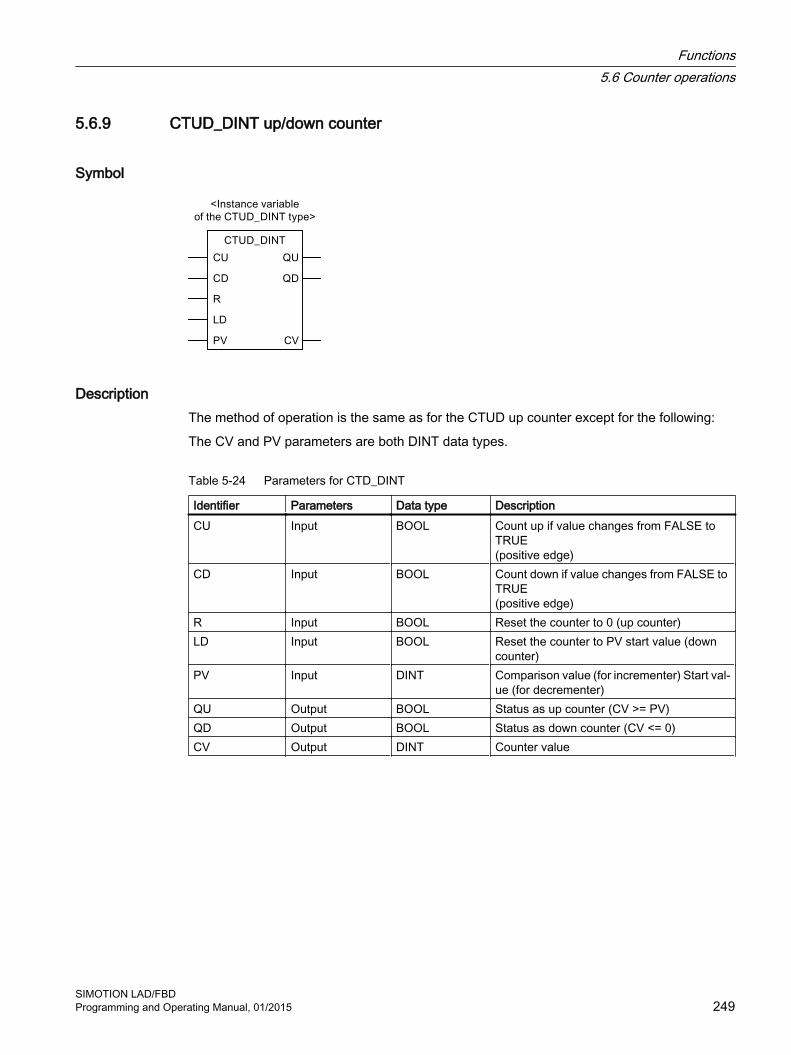
5.6.9 CTUD_DINT up/down counter
Symbol
DescriptionThe method of operation is the same as for the CTUD up counter except for the following:
The CV and PV parameters are both DINT data types.
Table 5-24 Parameters for CTD_DINT
Identifier Parameters Data type DescriptionCU Input BOOL Count up if value changes from FALSE to
TRUE (positive edge)
CD Input BOOL Count down if value changes from FALSE to TRUE (positive edge)
R Input BOOL Reset the counter to 0 (up counter)LD Input BOOL Reset the counter to PV start value (down
counter)PV Input DINT Comparison value (for incrementer) Start val‐
ue (for decrementer)QU Output BOOL Status as up counter (CV >= PV)QD Output BOOL Status as down counter (CV <= 0)CV Output DINT Counter value
Functions5.6 Counter operations
SIMOTION LAD/FBDProgramming and Operating Manual, 01/2015 249

5.6.10 CTUD_UDINT up/down counter
Symbol
DescriptionThe method of operation is the same as for the CTUD up counter except for the following:
The CV and PV parameters are both UDINT data types.
Table 5-25 Parameters for CTD_DINT
Identifier Parameter Data type DescriptionCU Input BOOL Count up if value changes from FALSE to
TRUE (positive edge)
CD Input BOOL Count down if value changes from FALSE to TRUE (positive edge)
R Input BOOL Reset the counter to 0 (up counter)LD Input BOOL Reset the counter to PV start value (down
counter)PV Input UDINT Comparison value (for incrementer) Start val‐
ue (for decrementer)QU Output BOOL Status as up counter (CV >= PV)QD Output BOOL Status as down counter (CV <= 0)CV Output UDINT Counter value
Functions5.6 Counter operations
SIMOTION LAD/FBD250 Programming and Operating Manual, 01/2015

5.7 Jump instructions
5.7.1 Overview of jump operations
DescriptionJump operations can be used in all logic blocks, e.g. programs, function blocks (FBs), and functions (FCs).
Jump label as operandThe operand of a jump operation is a jump label. The jump label specifies the point to where the program is to jump.
Enter the jump label via the JMP coil. The jump label consists of up to 480 characters. The first character must be a letter, the other characters can be either letters or numbers (e.g. SEG3).
Jump label as targetThe target jump label can be at the start of a network.
See alsoShowing/hiding a jump label (Page 78)
5.7.2 ---( JMP ) Jump in block if 1 (conditional)
Symbol<jump label>
---( JMP )
Description ---( JMP ) (Jump in block if 1) functions as a conditional jump if the pending signal of the previous logic operation is 1.
There must also be a target (LABEL) for every ---( JMP ).
The operations between the jump operation and the jump label are not executed!
Note
An unconditional jump is created by hanging the --( JMP ) element directly on the power rail.
Functions5.7 Jump instructions
SIMOTION LAD/FBDProgramming and Operating Manual, 01/2015 251
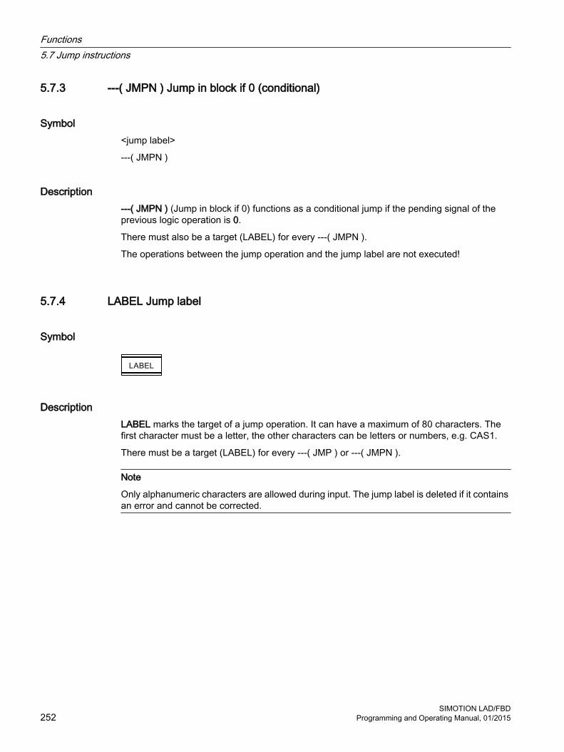
5.7.3 ---( JMPN ) Jump in block if 0 (conditional)
Symbol<jump label>
---( JMPN )
Description ---( JMPN ) (Jump in block if 0) functions as a conditional jump if the pending signal of the previous logic operation is 0.
There must also be a target (LABEL) for every ---( JMPN ).
The operations between the jump operation and the jump label are not executed!
5.7.4 LABEL Jump label
Symbol
DescriptionLABEL marks the target of a jump operation. It can have a maximum of 80 characters. The first character must be a letter, the other characters can be letters or numbers, e.g. CAS1.
There must be a target (LABEL) for every ---( JMP ) or ---( JMPN ).
Note
Only alphanumeric characters are allowed during input. The jump label is deleted if it contains an error and cannot be corrected.
Functions5.7 Jump instructions
SIMOTION LAD/FBD252 Programming and Operating Manual, 01/2015

5.8 Non-binary logic
Symbol e.g. AND
e.g. NOT
DescriptionLogic operations (AND, OR, XOR, NOT) are also provided as boxes with EN/ENO for non-binary values in the LAD/FBD editor.
The logical operations are listed in the table below.
There is only one operand for NOT.
Note
In the Command library tab of the project navigator, the elements AND, XOR, and OR, NOT are represented in the Logic entry.
Table 5-26 Non-binary logic
OperatorParameters
AND XOR OR NOT
IN1 ANY_BIT ANY_BIT ANY_BIT ANY_BITIN2 ANY_BIT ANY_BIT ANY_BIT EN BOOL BOOL BOOL BOOLENO BOOL BOOL BOOL BOOLOUT ANY_BIT ANY_BIT ANY_BIT ANY_BIT
Functions5.8 Non-binary logic
SIMOTION LAD/FBDProgramming and Operating Manual, 01/2015 253

5.9 Arithmetic operators
Symbol e.g. addition
DescriptionAn arithmetic expression is composed of arithmetic operators. These expressions allow numerical data types to be processed.
The divide operators DIV and MOD require that the second operand is not equal to zero.
Note
In the Command library tab of the project navigator, the elements ADD, SUB, MUL, and DIV are represented as +, -, *, and /.
The execution of a network, for example, is simply aborted in the event of an overflow, and the relevant/assigned event-triggered task (ExecutionFaultTask) is started.
The table below contains a list of the arithmetic operators:
Table 5-27 Arithmetic operators
Instruction Operator 1. Operand (IN1) 2. Operand (IN2) Result (OUT)Addition ADD ANY_NUM ANY_NUM ANY_NUM1
BYTE BYTE BYTEWORD WORD WORDDWORD DWORD DWORDTIME TIME TIME2
TOD TIME TOD2
DT TIME DT3
Multiplication MUL ANY_NUM ANY_NUM ANY_NUM1
BYTE BYTE BYTEWORD WORD WORDDWORD DWORD DWORDTIME ANY_INT TIME
Functions5.9 Arithmetic operators
SIMOTION LAD/FBD254 Programming and Operating Manual, 01/2015

Instruction Operator 1. Operand (IN1) 2. Operand (IN2) Result (OUT)Subtraction SUB ANY_NUM ANY_NUM ANY_NUM1
BYTE BYTE BYTEWORD WORD WORDDWORD DWORD DWORDTIME TIME TIMETOD TIME4 TODTOD TOD TIME5
DT TIME DTDT DT TIME5
Division DIV ANY_NUM ANY_NUM6 ANY_NUM1
BYTE BYTE6 BYTEWORD WORD6 WORDDWORD DWORD6 DWORDTIME ANY_INT6 TIMETIME TIME6 UDINT
Modulo division. MOD ANY_INT ANY_INT6 ANY_INT1
BYTE BYTE6 BYTEWORD WORD6 WORDDWORD DWORD6 DWORD
1 The data types of the operands and of the result must be identical.2 Addition, possibly with overflow.3 Addition with date correction.4 Restriction of TIME to TOD before calculation.5 These operations are based on the modulo of the maximum value of the TIME data type.6 The second operand must not be equal to zero.
Functions5.9 Arithmetic operators
SIMOTION LAD/FBDProgramming and Operating Manual, 01/2015 255

5.10 Numeric standard functionsEvery numeric standard function has an input parameter. The result is always the function value.
5.10.1 General numeric standard functions
Symbol e.g. absolute value
DescriptionGeneral numeric standard functions are used for:
● Calculation of the absolute value of a variable
● Calculation of the square root of a variable
The table below shows the general numeric standard functions:
Table 5-28 General numeric standard functions
Function name Input parameter data type (IN)
Function valuedata type (OUT)
Description
ABS ANY_NUM ANY_NUM1 Absolute valueSQRT ANY_REAL ANY_REAL1 Square root1 Identical to the data type of the input parameter IN
5.10.2 Logarithmic standard functions
Symbol e.g. exponential value
Functions5.10 Numeric standard functions
SIMOTION LAD/FBD256 Programming and Operating Manual, 01/2015

DescriptionLogarithmic standard functions are functions for calculating an exponential value or a logarithm of a value.
The table below shows the logarithmic standard functions:
Table 5-29 Logarithmic standard functions
Function name Input parameter data type (IN)
Data type of func‐tion value (OUT)
Description
EXP ANY_REAL ANY_REAL1 ex (natural exponential function)EXPD ANY_REAL ANY_REAL1 10x (decimal exponential function)EXPT ANY_REAL (IN1)
ANY_NUM (IN2)ANY_REAL2 Exponentiation
LN ANY_REAL ANY_REAL1 Natural logarithmLOG ANY_REAL ANY_REAL1 Common logarithm1 Identical to the data type of the input parameter IN2 Identical to the data type of the input parameter IN1
5.10.3 Trigonometric standard functions
Symbol e.g. COS
DescriptionThe trigonometric standard functions listed in the table expect and calculate variables of angles in radian measure.
Table 5-30 Trigonometric standard functions
Function name Input parameter data type
Data type of func‐tion value
Description
ACOS ANY_REAL ANY_REAL Arc cosine (main value)ASIN ANY_REAL ANY_REAL Arc sine (main value)ATAN ANY_REAL ANY_REAL Arc tangent (main value)COS ANY_REAL ANY_REAL Cosine (radian measure input)SIN ANY_REAL ANY_REAL Sine (radian measure input)TAN ANY_REAL ANY_REAL Tangent (radian measure input)
Functions5.10 Numeric standard functions
SIMOTION LAD/FBDProgramming and Operating Manual, 01/2015 257

5.11 Move
5.11.1 MOVE Transfer value
Symbol
Parameters Data type DescriptionEN BOOL Enable inputENO BOOL Enable outputIN ANY Source valueOUT ANY Destination address
DescriptionMOVE (Assign a value) is activated by the enable input EN. The value specified by the IN input is copied to the value specified in the OUT output. ENO has the same signal state as EN.
Functions5.11 Move
SIMOTION LAD/FBD258 Programming and Operating Manual, 01/2015

5.12 Shifting operations
5.12.1 Overview of shifting operations
Description The contents of input IN can be moved bit-by-bit to the left or right using shifting operations. A shift of n bits to the left multiplies the contents of input IN by 2 to the power of n; a shift of n bits to the right divides the contents of input IN by 2 to the power of n. If, for example, you move the binary equivalent of the decimal value 3 by 3 bits to the left, this gives the binary equivalent of the decimal value 24. Shift the binary equivalent of the decimal value 16 by 2 bits to the right, this gives the binary equivalent of the decimal value 4.
The number that you specify at input N indicates the number of bits by which to shift. The places which become free as a result of the shifting operation are filled up with zeroes.
The following shifting operations are available:
● shift bit to the left
● shift bit to the right
5.12.2 SHL Shift bit to the left
Symbol
Parameters Data type DescriptionEN BOOL Enable inputENO BOOL Enable outputIN ANY_BIT Value to be shiftedN USINT Number of bit positions to be shiftedOUT ANY_BIT Result of shifting operation
Functions5.12 Shifting operations
SIMOTION LAD/FBDProgramming and Operating Manual, 01/2015 259

Description SHL (e.g. shift left by 32 bits) is activated if the enable input (EN) has the signal state 1. The operation SHL shifts the bits 0 to 31 of the input IN bit-by-bit to the left. Input N specifies the number of bit positions to be shifted. If N is greater than 32, the command writes a 0 in the OUT output. The same number (N) of zeros is shifted from the right in order to occupy the positions which have become free. The result of the shifting operation can be queried at output OUT.
ENO has the same signal state as EN.
5.12.3 SHR Shift bit to the right
Symbol
Parameters Data type DescriptionEN BOOL Enable inputENO BOOL Enable outputIN ANY_BIT Value to be shiftedN USINT Number of bit positions to be shiftedOUT ANY_BIT Result of shifting operation
Description SHR (e.g. shift right by 32 bits) is activated if the enable input (EN) has the signal state 1. The operation SHR shifts the bits 0 to 31 of the input IN bit-by-bit to the right. Input N specifies the number of bit positions to be shifted. If N is greater than 32, the command writes a 0 in the OUT output. The same number (N) of zeros is shifted from the left in order to occupy the positions which have become free. The result of the shifting operation can be queried at output OUT.
ENO has the same signal state as EN.
Functions5.12 Shifting operations
SIMOTION LAD/FBD260 Programming and Operating Manual, 01/2015

5.13 Rotating operations
5.13.1 Overview of rotating operations
Description The entire contents of input IN can be rotated bit-by-bit to the left or right using rotating operations. The positions which become free are filled up with the signal states of the bits which have been moved out of the IN input.
At the input N you can specify the number of bits for the rotation.
5.13.2 ROL Rotate bit to the left
Symbol
Parameters Data type DescriptionEN BOOL Enable inputENO BOOL Enable outputIN ANY_BIT Value to be rotatedN USINT Number of bit positions to be rotatedOUT ANY_BIT Result of rotation operation
DescriptionROL (e.g. rotate left by 32 bits) is activated if the enable input (EN) has the signal state 1. The operation ROL rotates the entire contents of the IN input bit-by-bit to the left. Input N specifies the number of bit positions by which to rotate. If N is greater than 32, the double word IN is rotated by ((N-1) modulo 32)+1 positions. The bit positions coming from the right are occupied with the signal state of the bits which have been rotated to the left (left rotation). The result of the rotation operation can be queried at output OUT.
ENO has the same signal state as EN.
Functions5.13 Rotating operations
SIMOTION LAD/FBDProgramming and Operating Manual, 01/2015 261

Example
Figure 5-3 Representation in the FBD editor
Figure 5-4 Representation in the LAD editor
The ROL box is executed if %I 0.0 = 1. VAR1 is loaded and rotated to the left by the number of bits specified in VAR2. The result is written to VAR3. %Q 4.0 is set.
5.13.3 ROR Rotate bit to the right
Symbol
Parameter Data type DescriptionEN BOOL Enable inputENO BOOL Enable outputIN ANY_BIT Value to rotateN USINT Number of bit positions to rotateOUT ANY_BIT Result of rotation operation
Functions5.13 Rotating operations
SIMOTION LAD/FBD262 Programming and Operating Manual, 01/2015

DescriptionROR (e.g. rotate right by 32 bits) is activated if the enable input (EN) has the signal state 1. The operation ROR rotates the entire contents of the IN input bit-by-bit to the right. Input N specifies the number of bit positions by which to rotate. If N is greater than 32, the double word IN is rotated by ((N-1) modulo 32)+1 positions. The bit positions coming from the left are occupied by the signal state of the bits which have been rotated to the right (right rotation). The result of the rotation operation can be queried at output OUT.
ENO has the same signal state as EN.
Example
Figure 5-5 Representation in the LAD editor
Figure 5-6 Representation in the FBD editor
The ROR box is executed if %I 0.0 = 1. VAR1 is loaded and rotated to the right by the number of bits specified in VAR2. The result is written to VAR3. %Q 4.0 is set.
Functions5.13 Rotating operations
SIMOTION LAD/FBDProgramming and Operating Manual, 01/2015 263

5.14 Program control instructions
5.14.1 Calling up an empty box
Symbol
Parameters Data type DescriptionEN BOOL Enable inputENO BOOL Enable output<Type> FB / FC FC/FB type<Instance variable> FB FB instance variable
DescriptionThe symbol for an empty box depends on the function block/function (according to how many parameters there are). EN, ENO and the name of the FB/FC must be available.
You do not have to specify EN/ENO in the variable declaration. The input and output are automatically allocated by the system.
The EN input can be used to inhibit a block call and redirect the block of the EN input to the ENO output.
It is not possible to control the ENO output in the block itself.
Note
You can use an empty box to insert a call (Page 86). As soon as you enter the type, the box transforms and displays the parameters of the specified FB/FC call.
See alsoInserting LAD/FBD elements (Page 86)
5.14.2 RET Jump back
Symbol ---( RET )
Functions5.14 Program control instructions
SIMOTION LAD/FBD264 Programming and Operating Manual, 01/2015

DescriptionRET (jump back) is used for the conditional exit from blocks. A preceding logic operation is necessary for this output.
Example
Figure 5-7 Representation in the LAD editor
Figure 5-8 Representation in the FBD editor
The operation is executed if %I 0.0 = 1.
Functions5.14 Program control instructions
SIMOTION LAD/FBDProgramming and Operating Manual, 01/2015 265

5.15 Timer instructions
5.15.1 TP pulse
Symbol
DescriptionWith a signal state change from 0 to 1 at the IN input, time ET is started. Output Q remains at 1 until elapsed time ET is equal to programmed time value PT. As long as time ET is running, the IN input has no effect.
Figure 5-9 Mode of operation of TP pulse timer
Table 5-31 Call parameters for TP
Identifier Parameters Data type DescriptionIN Input Input Start inputPT Input TIME Duration of pulseQ Output BOOL Status of timeET Output TIME Elapsed time
Functions5.15 Timer instructions
SIMOTION LAD/FBD266 Programming and Operating Manual, 01/2015
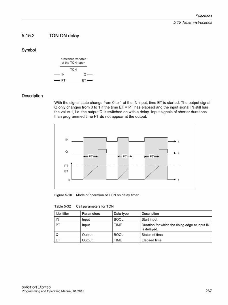
5.15.2 TON ON delay
Symbol
DescriptionWith the signal state change from 0 to 1 at the IN input, time ET is started. The output signal Q only changes from 0 to 1 if the time ET = PT has elapsed and the input signal IN still has the value 1, i.e. the output Q is switched on with a delay. Input signals of shorter durations than programmed time PT do not appear at the output.
Figure 5-10 Mode of operation of TON on delay timer
Table 5-32 Call parameters for TON
Identifier Parameters Data type DescriptionIN Input BOOL Start inputPT Input TIME Duration for which the rising edge at input IN
is delayed.Q Output BOOL Status of timeET Output TIME Elapsed time
Functions5.15 Timer instructions
SIMOTION LAD/FBDProgramming and Operating Manual, 01/2015 267

5.15.3 TOF OFF delay
Symbol
DescriptionWith a signal state change from 0 to 1 at start input IN, state 1 appears at output Q. If the state at the start input IN changes from 1 to 0, then time ET is started. If a change occurs at input IN from 0 to 1 before time ET has elapsed, then the timer operation is reset. A start is initiated again when the state at input IN changes from 1 to 0. Only after the duration ET = PT has elapsed does output Q adopt a signal state of 0. This means that the output is switched off with a delay.
Figure 5-11 Mode of operation of TOF off delay timer
Table 5-33 Call parameters for TOF
Identifier Parameters Data type DescriptionIN Input BOOL Start inputPT Input TIME Duration for which the falling edge at input IN
is delayed.Q Output BOOL Status of timeET Output TIME Elapsed time
Functions5.15 Timer instructions
SIMOTION LAD/FBD268 Programming and Operating Manual, 01/2015

5.16 Selection functions
5.16.1 SEL Binary selection
Symbol
Parameters Input parameter data type
Description
EN BOOL Enable inputENO BOOL Enable outputG BOOL Input parameterIN0 ANY Input parameterIN1 ANY Input parameter
DescriptionThe function value is one of the input parameters IN0 or IN1, depending on the value of the input parameter G.
The input parameters IN0 and IN1 must be the same data type or must be capable of implicit conversion into the same data type.
The return value is data type ANY.
Selected input parameter
IN0 if G = 0 (FALSE)
IN1 if G = 1 (TRUE)
The data type corresponds to the common data type of the input parameters IN0 and IN1.
Functions5.16 Selection functions
SIMOTION LAD/FBDProgramming and Operating Manual, 01/2015 269

5.16.2 MAX Maximum function
Symbol
Parameter Input parameter data type
Description
EN BOOL Enable inputENO BOOL Enable outputIN0 ANY_ELEMENTARY Input parameterIN1 ANY_ELEMENTARY Input parameter
DescriptionThe function value is the maximum value of both input parameters IN0 and IN1.
The input parameters IN0 and IN1 must be the same data type or must be capable of implicit conversion into the most powerful data type.
The return value is of data type ANY_ELEMENTARY.
Maximum of the input parameters.
The data type corresponds to the most powerful data type of the input parameters IN0 and IN1.
5.16.3 MIN Minimum function
Symbol
Parameter Input parameter data type
Description
EN BOOL Enable inputENO BOOL Enable outputIN0 ANY_ELEMENTARY Input parameterIN1 ANY_ELEMENTARY Input parameter
Functions5.16 Selection functions
SIMOTION LAD/FBD270 Programming and Operating Manual, 01/2015

DescriptionThe function value is the minimum value of both input parameters IN0 and IN1.
All IN0 and IN1 input parameters must be the same data type or capable of implicit conversion into the most powerful data type.
The return value is of data type ANY_ELEMENTARY.
Minimum of the input parameters.
The data type corresponds to the most powerful data type of the input parameters IN0 and IN1.
5.16.4 LIMIT Limiting function
Symbol
Parameters Input parameter data type
Description
EN BOOL Enable inputENO BOOL Enable outputMN ANY_ELEMENTARY Input parameter
Lower limiting valueIN ANY_ELEMENTARY Input parameter
Value to be limitedMX ANY_ELEMENTARY Input parameter
Upper limiting value
DescriptionThe input parameter IN is limited to values lying between the lower limit value MN and the upper limit value MX.
All input parameters must be the same data type or capable of conversion into the most powerful data type by implicit conversion.
The return value is of data type ANY_ELEMENTARY.
MIN (MAX (IN, MN), MX)
The data type corresponds to the most powerful data type of the input parameters.
Functions5.16 Selection functions
SIMOTION LAD/FBDProgramming and Operating Manual, 01/2015 271

5.16.5 MUX Multiplex function
Symbol
Parameters Input parameter data type
Description
EN BOOL Enable inputENO BOOL Enable outputC ANY_INT Input parameterIN0 ANY Input parameterIN1 ANY Input parameter
DescriptionThe function value is one of the two input parameters IN0 or IN1, depending on the value of the input parameter K.
The input parameters IN0 and IN1 must be the same data type or must be capable of implicit conversion into the same data type.
The return value is data type ANY.
The data type corresponds to the common data type of the input parameters IN0 and IN1.
Functions5.16 Selection functions
SIMOTION LAD/FBD272 Programming and Operating Manual, 01/2015

Commissioning (software) 66.1 Commissioning
This chapter describes how to assign created programs to the task system of a control unit and how to download them to the target system.
SIMOTION LAD/FBDProgramming and Operating Manual, 01/2015 273

6.2 Assigning programs to a taskPrograms must be assigned to a task before they can be downloaded to the target system (the SIMOTION device).
Various tasks are made available by SIMOTION, each with different priorities or system responses (e.g. during initialization).
Further information can be found in the SIMOTION SCOUT Basic Functions Function Manual, and in SIMOTION online help.
Assigning programs to a task:
1. In the project navigator, double-click under the corresponding SIMOTION device the EXECUTION SYSTEM element.The configuration window for the execution system opens.
2. Select the required task (e.g. MotionTask_1) from the left pane.
3. Select the Program assignment tab.
4. Select the program to be assigned from the Programs list.
Commissioning (software)6.2 Assigning programs to a task
SIMOTION LAD/FBD274 Programming and Operating Manual, 01/2015

5. Click the button >>.
6. Select the Task configuration tab to specify additional settings for the task if required.
Figure 6-1 Configure execution system
Figure 6-2 Assigning a program to a motion task
Commissioning (software)6.2 Assigning programs to a task
SIMOTION LAD/FBDProgramming and Operating Manual, 01/2015 275
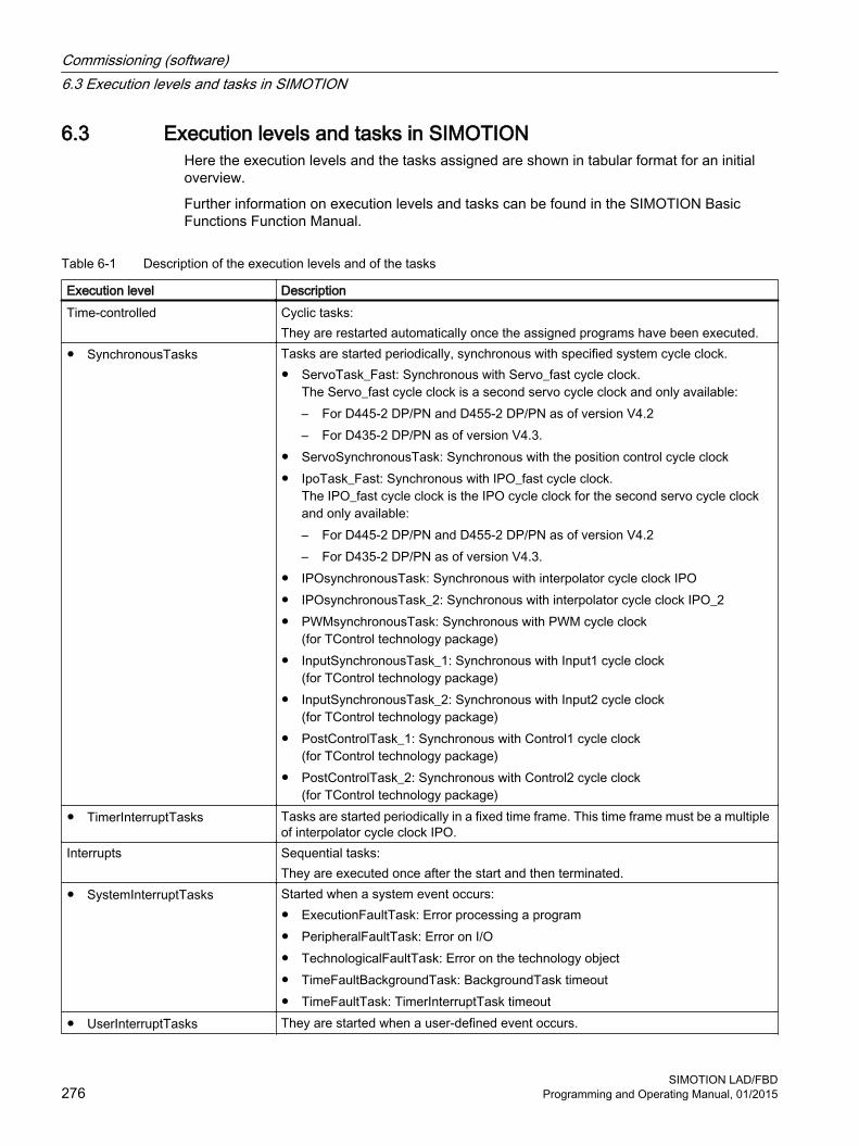
6.3 Execution levels and tasks in SIMOTIONHere the execution levels and the tasks assigned are shown in tabular format for an initial overview.
Further information on execution levels and tasks can be found in the SIMOTION Basic Functions Function Manual.
Table 6-1 Description of the execution levels and of the tasks
Execution level DescriptionTime-controlled Cyclic tasks:
They are restarted automatically once the assigned programs have been executed.● SynchronousTasks Tasks are started periodically, synchronous with specified system cycle clock.
● ServoTask_Fast: Synchronous with Servo_fast cycle clock.The Servo_fast cycle clock is a second servo cycle clock and only available:– For D445‑2 DP/PN and D455‑2 DP/PN as of version V4.2– For D435‑2 DP/PN as of version V4.3.
● ServoSynchronousTask: Synchronous with the position control cycle clock● IpoTask_Fast: Synchronous with IPO_fast cycle clock.
The IPO_fast cycle clock is the IPO cycle clock for the second servo cycle clock and only available:– For D445‑2 DP/PN and D455‑2 DP/PN as of version V4.2– For D435‑2 DP/PN as of version V4.3.
● IPOsynchronousTask: Synchronous with interpolator cycle clock IPO● IPOsynchronousTask_2: Synchronous with interpolator cycle clock IPO_2● PWMsynchronousTask: Synchronous with PWM cycle clock
(for TControl technology package)● InputSynchronousTask_1: Synchronous with Input1 cycle clock
(for TControl technology package)● InputSynchronousTask_2: Synchronous with Input2 cycle clock
(for TControl technology package)● PostControlTask_1: Synchronous with Control1 cycle clock
(for TControl technology package)● PostControlTask_2: Synchronous with Control2 cycle clock
(for TControl technology package)● TimerInterruptTasks Tasks are started periodically in a fixed time frame. This time frame must be a multiple
of interpolator cycle clock IPO.Interrupts Sequential tasks:
They are executed once after the start and then terminated.● SystemInterruptTasks Started when a system event occurs:
● ExecutionFaultTask: Error processing a program● PeripheralFaultTask: Error on I/O● TechnologicalFaultTask: Error on the technology object● TimeFaultBackgroundTask: BackgroundTask timeout● TimeFaultTask: TimerInterruptTask timeout
● UserInterruptTasks They are started when a user-defined event occurs.
Commissioning (software)6.3 Execution levels and tasks in SIMOTION
SIMOTION LAD/FBD276 Programming and Operating Manual, 01/2015

Execution level DescriptionRound robin MotionTasks and BackgroundTasks share the free time remaining after execution of
the higher-priority system and user tasks. The proportion of the two levels can be assigned.
● MotionTasks Sequential tasks:They are executed once after the start and then terminated. Start takes place:● Explicitly via a task control command in a program assigned to another task.● Automatically when RUN operating state is attained if the corresponding attribute
was set during task configuration.The priority of a MotionTask can be increased temporarily:● In the MCC programming language with the "Wait for..." commands, see Wait for
axis, Wait for signal, Wait for condition.● In the ST programming language with the WAITFORCONDITION statement.
● BackgroundTask Cyclic task:It is restarted automatically once the assigned programs have been executed. The task cycle time depends on the runtime.
StartupTask Task is executed once when there is a transition from STOP or STOP U operating state to RUN operating state.SystemInterruptTasks are started by their triggering system event.
ShutdownTask Task is executed once when there is a transition from RUN operating state to STOP or STOP U operating state.STOP or STOP U operating state is reached by:● Activating the operating state switch● Calling the relevant system function, for example, MCC Change operating state
command ● Occurrence of a fault with the appropriate error responseSystemInterruptTasks and PeripheralFaultTasks are started by their triggering system event.
For information on the behavior of sequential and cyclic tasks:● During initialization of local program variables:
See Initialization of local variables (Page 128).● In the event of execution errors in the program:
See SIMOTION Basic Functions Function Manual.For information about options for accessing the process image and I/O variables:see Important properties for direct access and process image (Page 138).
Commissioning (software)6.3 Execution levels and tasks in SIMOTION
SIMOTION LAD/FBDProgramming and Operating Manual, 01/2015 277

6.4 Task start sequenceWhen the StartupTask is completed, RUN mode is reached.
The following tasks are then started:
● SynchronousTasks
● TimerInterruptTasks
● BackgroundTask
● MotionTasks with startup attribute.
Note
The sequence in which these tasks are first started after RUN mode has been reached does not conform to the task priorities.
Figure 6-3 Task configuration of a motion task
Commissioning (software)6.4 Task start sequence
SIMOTION LAD/FBD278 Programming and Operating Manual, 01/2015

6.5 Downloading programs to the target systemThe program has to be downloaded into the target system, together with the technology objects etc., before being executed.
To download the program to the target system, proceed as follows:
1. Select Project > Save and recompile all.The project is locally saved on the hard disk and compiled, with due regard for all dependencies.
2. Select the Project > Check consistency menu command to check the project for consistency.This is not necessary if the Check consistency before loading option is activated under Options > Settings on the Download tab (this option is activated by default). This means the consistency check is performed automatically during the download to the target system.
3. Select the Project > Connect to selected target devices menu command or click .Online mode is activated.
4. Select the Target system > Load > Download project to target system menu command or click .The project data (including the sample program) and the data of the hardware configuration are downloaded to the RAM of the target system.
For more information about downloading a program to the target system, see the SIMOTION Basic Functions Function Manual.
Commissioning (software)6.5 Downloading programs to the target system
SIMOTION LAD/FBDProgramming and Operating Manual, 01/2015 279

Commissioning (software)6.5 Downloading programs to the target system
SIMOTION LAD/FBD280 Programming and Operating Manual, 01/2015

Debugging Software / Error Handling 77.1 Operating modes for program testing
7.1.1 Modes of the SIMOTION devicesVarious SIMOTION device operating modes are available for program testing.
Table 7-1 Operating modes of a SIMOTION device
Operating mode MeaningProcess mode Program execution on the SIMOTION device is optimized for maximum system performance.
The following diagnostic functions are available, although they may have only restricted function‐ality because of the optimization for maximum system performance:● Monitor variables in the symbol browser or a watch table● Program status (only restricted):
– Restricted monitoring of variables (e.g. variables in loops, return values for system functions).
– Maximum of 1 program source (e.g. ST source file, MCC unit, LAD/FBD unit)1 can be monitored.
● Trace tool (only restricted) with measuring functions for drives and function generator, see online help:– Maximum of 1 trace on each SIMOTION device.
Test mode The diagnostic functions of the process mode are available to the full extent:● Monitor variables in the symbol browser or a watch table● Program status:
– Monitoring of all variables possible.– As of version V4.0 of the SIMOTION Kernel:
Several program sources (e.g. ST source files, MCC units, LAD/FBD units)1 can be monitored per task.
– For version V3.2 of the SIMOTION Kernel:Maximum of 1 program source (e.g. ST source file, MCC unit, LAD/FBD unit)1 can be monitored per task.
● Trace tool with measuring functions for drives and function generator, see online help:– Maximum of 4 traces on each SIMOTION device.
In addition, the following diagnostics function is available:● Trace for monitoring the program execution in program branches which are executed cyclically
(only for the MCC programming language and for SIMOTION Kernel V4.2 and higher).
NoteRuntime and memory utilization increase as the use of diagnostic functions increases.
SIMOTION LAD/FBDProgramming and Operating Manual, 01/2015 281

Operating mode MeaningDebug mode In addition to the diagnostic functions of the test mode, you can use the following functions:
● BreakpointsWithin a program source, you can set breakpoints (Page 302). When an activated breakpoint is reached, selected tasks will be stopped.
● Controlling MotionTasksOn the "Task Manager" tab of the device diagnostics, you can use task control commands for MotionTasks; see the SIMOTION Basic Functions Function Manual.
No more than 1 SIMOTION device of the project can be switched to debug mode. SIMO‐TION SCOUT is in online mode, i.e. connected to the target system.Observe the following section: Important information about the life-sign monitoring (Page 283).
1 Each with 1 MCC chart or 1 LAD/FBD program in a program source.
Selecting the operating modeHow to select the operating mode of a SIMOTION device:
1. Make sure a connection to the target system has been established (online mode).
2. Highlight the SIMOTION device in the project navigator.
3. Select the "Operating mode" context menu.
4. Select the required operating mode (see the table above).If you have selected "Debug mode":
– Accept the safety information.
– Parameterize the sign-of-life monitoring.
Observe the following section: Important information about the life-sign monitoring (Page 283).
5. Confirm with OK.The SIMOTION device switches to the selected operating mode (apart from with debug mode; see the explanation below).
Special features with debug modeDebug mode can only be selected for one SIMOTION device.
If you have selected debug mode, only SIMOTION SCOUT switches to it; the SIMOTION device is in test mode.
● The project navigator indicates that debug mode is activated for SIMOTION SCOUT by means of a symbol next to the SIMOTION device.
● The breakpoints toolbar (Page 307) is displayed.
Debug mode is not enabled for the SIMOTION device until at least one set breakpoint is activated. If all breakpoints are deactivated, debug mode is canceled for the SIMOTION device.
The status bar indicates that debug mode is activated for the SIMOTION device.
Debugging Software / Error Handling7.1 Operating modes for program testing
SIMOTION LAD/FBD282 Programming and Operating Manual, 01/2015

7.1.2 Important information about the life-sign monitoring.
WARNING
Dangerous plant states possible
If problems occur in the communication link between the PC and the SIMOTION device, this may result in dangerous plant states (e.g. the axis may start moving in an uncontrollable manner).
Therefore, use the debug mode or a control panel only with the life-sign monitoring function activated with a suitably short monitoring time!
You must observe the appropriate safety regulations.
The function is released exclusively for commissioning, diagnostic and service purposes. The function should generally only be used by authorized technicians. The safety shutdowns of the higher-level control have no effect.
Therefore, there must be an EMERGENCY STOP circuit in the hardware. The appropriate measures must be taken by the user.
In the following cases, the SIMOTION device and SIMOTION SCOUT regularly exchange life-signs to ensure a correctly functioning connection:
● In debug mode with activated breakpoints.
● When controlling an axis or a drive via the control panel (control priority at the PC):
If the exchange of the life-signs is interrupted longer than the set monitoring time, the following reactions are triggered:
● In debug mode for activated breakpoints:
– The SIMOTION device switches to the STOP operating state.
– The outputs are deactivated (ODIS).
● For controlling an axis or a drive using the control panel (control priority for the PC):
– The axis is brought to a standstill.
– The enables are reset.
Accept safety notesAfter selecting the debug mode or a control panel, you must accept the safety notes. You can set the parameters for the life-sign monitoring.
Proceed as follows:
1. Click the Settings button.The "Debug Settings" window opens.
2. Read there, as described in the following section, the safety notes and parameterize the life-sign monitoring.
Debugging Software / Error Handling7.1 Operating modes for program testing
SIMOTION LAD/FBDProgramming and Operating Manual, 01/2015 283

Parameterizing the life-sign monitoringIn the "Life-Sign Monitoring Parameters" window, proceed as described below:
1. Read the warning!
2. Click the Safety notes button to open the window with the detailed safety notes.
3. Do not make any changes to the defaults for life-sign monitoring.Changes should only be made in special circumstances and in observance of all danger warnings.
4. Click Accept to confirm you have read the safety notes and have correctly parameterized the life-sign monitoring.
Note
The life-sign monitoring also responds in the following cases:● Pressing the spacebar.● Switching to a different Windows application.● Too high a communication load between the SIMOTION device and SIMOTION SCOUT
(e.g. by uploading task trace data).
The following reactions are triggered:● In debug mode for activated breakpoints:
– The SIMOTION device switches to the STOP operating state.– The outputs are deactivated (ODIS).
● For controlling an axis or a drive using the control panel (control priority for the PC):– The axis or the drive is brought to a standstill.– The enables are reset.
WARNING
Dangerous plant states possible
This function is not guaranteed in all operating states.
Therefore, there must be an EMERGENCY STOP circuit in the hardware. The appropriate measures must be taken by the user.
Debugging Software / Error Handling7.1 Operating modes for program testing
SIMOTION LAD/FBD284 Programming and Operating Manual, 01/2015

7.1.3 Life-sign monitoring parameters
Table 7-2 Life-sign monitoring parameter description
Field DescriptionLife-sign monitoring The SIMOTION device and SIMOTION SCOUT regularly ex‐
change life-signs to ensure a correctly functioning connection. If the exchange of the life-signs is interrupted longer than the set monitoring time, the following reactions are triggered:● In debug mode for activated breakpoints:
– The SIMOTION device switches to the STOP operating state.
– The outputs are deactivated (ODIS).● For controlling an axis or a drive using the control panel
(control priority for the PC):– The axis is brought to a standstill.– The enables are reset.
The following parameterizations are possible:● Checkbox active:
If the checkbox is activated, life-sign monitoring is active.The deactivation of the life-sign monitoring is not always possible.
● Monitoring time:Enter the timeout.
PrudenceDo not make any changes to the defaults for life-sign monitoring, if possible.Changes should only be made in special circumstances and in observance of all danger warnings.
Safety information Please observe the warning!Click the button to obtain further safety information.See: Important information about the life-sign monitoring (Page 283)
Debugging Software / Error Handling7.1 Operating modes for program testing
SIMOTION LAD/FBDProgramming and Operating Manual, 01/2015 285

7.2 Editing program sources in online mode
Online editing in process or test modeIf SIMOTION SCOUT is connected to a target system which is in the "process mode" or "test mode" operating mode, program sources (e.g. ST source files, MCC units with MCC charts) can generally be edited, compiled, and loaded to the target system in STOP operating mode. For information on downloading in RUN operating mode, see the corresponding section in the "SIMOTION Basic Functions" Function Manual.
However, you can only activate the "program status", "monitor program execution" (only for MCC), and trace (only for MCC) test functions for a program source or a program organization unit (POU) if the following conditions are met:
1. This program source or any POU of this source (e.g. MCC chart) does not contain any changes which have not been saved.
2. The program source (unit) in SCOUT is consistent with the target system.
Note
If the "program status" test function is activated, editing of the corresponding program source or one of its POUs is disabled.
If an MCC unit or MCC chart is changed and the "monitor program execution" or trace test functions are active for that unit or chart, the test functions are canceled.
Online editing in debug modeIf SIMOTION SCOUT is in debug mode, editing is possible as long as the SIMOTION device is not in debug mode, i.e. no breakpoints are activated.
You can only activate breakpoints and, as a result, switch the SIMOTION device to debug mode if the corresponding program source and all its POUs are saved, compiled so they are up to date, and consistent with the target system.
If you attempt to edit a program source or POU when the SIMOTION device is in debug mode, you are requested to deactivate all breakpoints and, as a result, to switch the SIMOTION device out of debug mode.
Note
If breakpoints have been activated and the SIMOTION device is in debug mode:
Entering a space switches the SIMOTION device to STOP operating mode and deactivates all outputs (ODIS).
Debugging Software / Error Handling7.2 Editing program sources in online mode
SIMOTION LAD/FBD286 Programming and Operating Manual, 01/2015

7.3 Symbol Browser
7.3.1 CharacteristicsIn the symbol browser, you can view and, if necessary, change the name, data type, and variable values. You can see the following variables in particular:
● Unit variables and static variables of a program or function block
● System variables of a SIMOTION device or a technology object
● I/O variables or global device variables.
For these variables, you can:
● View a snapshot of the variable values
● Monitor variable values as they change
● Change (modify) variable values
However, the symbol browser can only display/modify the variable values if the project has been loaded in the target system and a connection to the target system has been established.
7.3.2 Using the symbol browser
Requirements● Make sure that a connection to the target system has been established and a project has
been downloaded to the target system (see Download programs to the target system (Page 279)).
● You can run the user program, but you do not have to. If the program is not run, you only see the initial values of the variables.
The procedure depends on the memory area in which the variables to be monitored are stored.
ProcedureProceed as follows:
1. Select the appropriate element in the project navigator in accordance with the following table.
2. In the detail view, click the Symbol browser tab.The corresponding variables are displayed in the symbol browser.
3. Select how each variable in the "Display format" column should be displayed.
Debugging Software / Error Handling7.3 Symbol Browser
SIMOTION LAD/FBDProgramming and Operating Manual, 01/2015 287

Table 7-3 Elements in the project navigator and variables to be monitored in the symbol browser
Variables to be monitored in the symbol browser Element to be selected in the project navigator
Variables in the unit's user memory or in the retentive memory, see SIMOTION ST Programming and Operating Manual:● Retentive and non-retentive unit variables of the interface section of a program
source (unit)● Retentive and non-retentive unit variables of the implementation section of a
program source (unit)● Static variables of the function blocks whose instances are declared as unit
variables.● In addition, if the program source (unit) has been compiled with the "Only create
program instance data once" compiler option (Page 59):– Static variables of the programs.– Static variables of the function blocks whose instances are declared as static
variables of programs.
Program source (unit)
Variables in the user memory of the task, see SIMOTION ST Programming and Oper‐ating Manual:If the program source (unit) was compiled without the "Only create program instance data once" (default) compiler option (Page 59), the user memory of the task to which the program was assigned contains the following variables:● Static variables of the programs.● Static variables of the function blocks whose instances are declared as static
variables of programs.
EXECUTION SYSTEM
System variables of a SIMOTION device SIMOTION deviceSystem variables of a technology object Instance of the technology objectGlobal device variables GLOBAL DEVICE VARIABLESI/O variables (in the Address list tab of the detail view). The Address list tab of the detail view can be opened by double-clicking the ADDRESS LIST element in the project navigator.
ADDRESS LIST
Note
You can monitor temporary variables (together with unit variables and static variables) with Program status (see Properties of the program status (Page 297)).
NoteTrace diagnostic function for MCC programming
Various internal variables, whose identifier begins with an underscore, are automatically created by the compiler for the trace diagnostic function. These variables are displayed in the symbol browser.
With activated diagnostic function, these variables are used for the control of the diagnostics function. These variables must not be used in the user program.
Debugging Software / Error Handling7.3 Symbol Browser
SIMOTION LAD/FBD288 Programming and Operating Manual, 01/2015

Status and controlling variablesIn the Status value column, the current variable values are displayed and periodically updated.
You can change the value of one or several variables. Proceed as follows for the variables to be changed:
1. Enter a value in the Control value column.
2. Activate the checkbox in this column
3. Click the Immediate control button.
The values you entered are written to the selected variables.
WARNING
Dangerous plant states possible
You assign the entered values to the variables during control. This can result in dangerous plant states, e.g. unexpected axis motion.
Note
Note when you change the values of several variables:
The values are written sequentially to the variables. It can take several milliseconds until the next value is written. The variables are changed from top to bottom in the symbol browser. There is therefore no guarantee of consistency.
Working with the symbol browserThe functions of the symbol browser and how you work with them are described in detail in the online help.
Display invalid floating-point numbersInvalid floating-point numbers are displayed as follows in the symbol browser (independently of the SIMOTION device):
Table 7-4 Display invalid floating-point numbers
Display Meaning1.#QNAN-1.#QNAN
Invalid bit pattern in accordance with IEEE 754 (NaN Not a Number). There is no distinction between signaling NaN (NaNs) and quiet NaN (NaNq).
1.#INF-1.#INF
Bit pattern for + infinity in accordance with IEEE 754Bit pattern for – infinity in accordance with IEEE 754
-1.#IND Bit pattern for indeterminate
Debugging Software / Error Handling7.3 Symbol Browser
SIMOTION LAD/FBDProgramming and Operating Manual, 01/2015 289
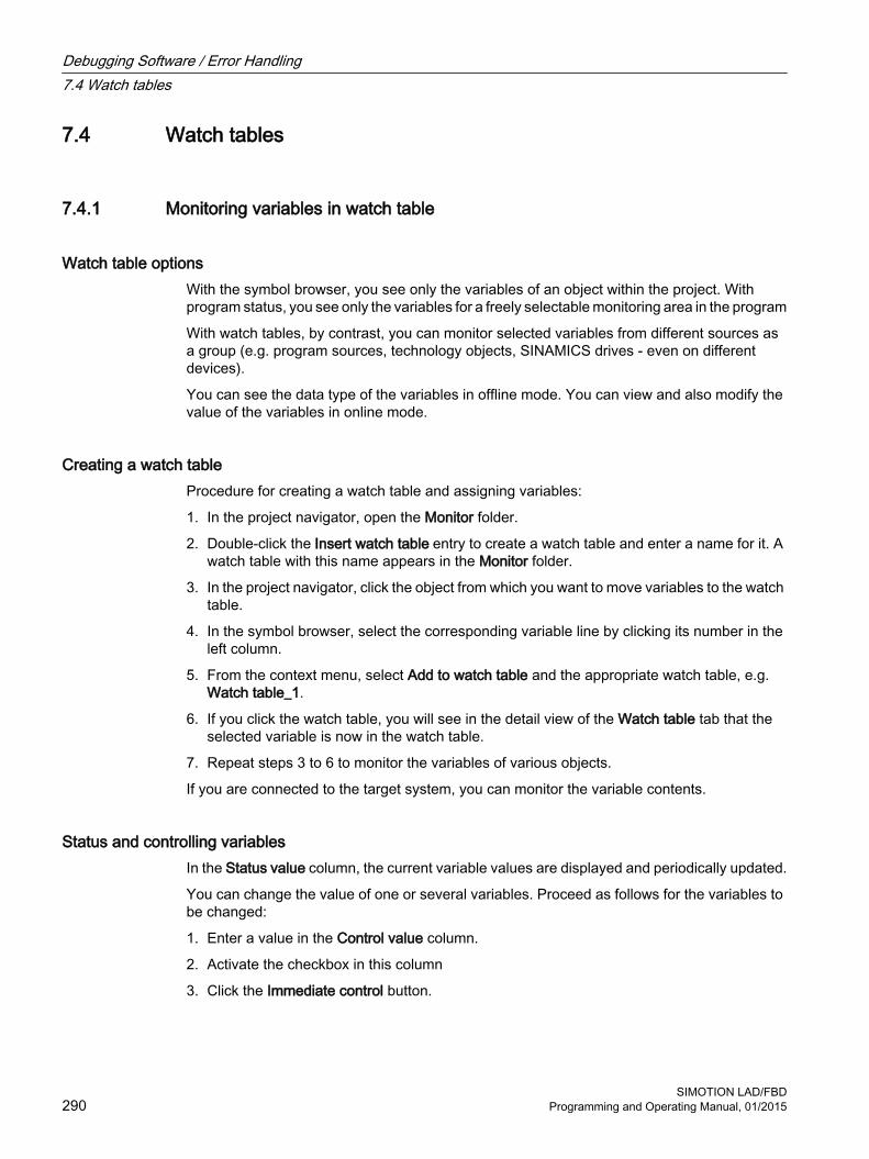
7.4 Watch tables
7.4.1 Monitoring variables in watch table
Watch table optionsWith the symbol browser, you see only the variables of an object within the project. With program status, you see only the variables for a freely selectable monitoring area in the program
With watch tables, by contrast, you can monitor selected variables from different sources as a group (e.g. program sources, technology objects, SINAMICS drives - even on different devices).
You can see the data type of the variables in offline mode. You can view and also modify the value of the variables in online mode.
Creating a watch tableProcedure for creating a watch table and assigning variables:
1. In the project navigator, open the Monitor folder.
2. Double-click the Insert watch table entry to create a watch table and enter a name for it. A watch table with this name appears in the Monitor folder.
3. In the project navigator, click the object from which you want to move variables to the watch table.
4. In the symbol browser, select the corresponding variable line by clicking its number in the left column.
5. From the context menu, select Add to watch table and the appropriate watch table, e.g. Watch table_1.
6. If you click the watch table, you will see in the detail view of the Watch table tab that the selected variable is now in the watch table.
7. Repeat steps 3 to 6 to monitor the variables of various objects.
If you are connected to the target system, you can monitor the variable contents.
Status and controlling variablesIn the Status value column, the current variable values are displayed and periodically updated.
You can change the value of one or several variables. Proceed as follows for the variables to be changed:
1. Enter a value in the Control value column.
2. Activate the checkbox in this column
3. Click the Immediate control button.
Debugging Software / Error Handling7.4 Watch tables
SIMOTION LAD/FBD290 Programming and Operating Manual, 01/2015

The values you entered are written to the selected variables.
WARNING
Dangerous plant states possible
You assign the entered values to the variables during control. This can result in dangerous plant states, e.g. unexpected axis motion.
Note
Note when you change the values of several variables:
The values are written sequentially to the variables. It can take several milliseconds until the next value is written. The variables are changed from top to bottom in the watch table. There is therefore no guarantee of consistency.
Working with the watch tableThe functions of the watch table and how you work with them are described in detail in the Online help.
Display invalid floating-point numbersInvalid floating-point numbers are displayed as follows in the watch table (independently of the SIMOTION device):
Table 7-5 Display invalid floating-point numbers
Display Meaning1.#QNAN-1.#QNAN
Invalid bit pattern in accordance with IEEE 754 (NaN Not a Number). There is no distinction between signaling NaN (NaNs) and quiet NaN (NaNq).
1.#INF-1.#INF
Bit pattern for + infinity in accordance with IEEE 754Bit pattern for – infinity in accordance with IEEE 754
-1.#IND Bit pattern for indeterminate
Debugging Software / Error Handling7.4 Watch tables
SIMOTION LAD/FBDProgramming and Operating Manual, 01/2015 291

7.5 Variable status"Variable status" enables you to monitor the current value for an individual variable, selected using the cursor, in an open program source or program organization unit (e.g. ST source file, MCC chart, LAD program).
Requirements● Make sure that a connection to the target system has been established and a project has
been downloaded to the target system. For information on loading a project, see "Downloading programs to the target system (Page 279)".
● The program source containing the program organization unit (POE) whose variables you want to monitor must be consistent with the target system.
● The associated source (e.g. ST source file, MCC chart, LAD program) must be open.
● With the MCC programming language only: The parameter screen form for the command in which the variable you want to monitor is being used must be open.
● You can run the user program, but you do not have to. If the program is not run, you only see the initial values of the variables.
ProcedureTo monitor an individual variable using variable status:
1. Position the cursor above the identifier for a variable.
– With the ST programming language: in the open ST source file
– With the ST programming language: within an input field in the open parameter screen form
– With the LAD/FBD programming language: within a network of the LAD/FBD program
2. Briefly position the cursor above the identifier.
The tool tip shows the current value of the variable. If you keep the cursor above the identifier for a longer period, the value is updated on an ongoing basis.
Note
With "variable status", the current value for the variable is displayed, wherever the selected variable is being used.
The "variable status" function enables you to monitor all those variables you are also able to monitor in the symbol browser (Page 287) or the address list. These are:
● System variables of SIMOTION devices
● System variables of technology objects
● Global device variables
● Retentive and non-retentive unit variables of the interface section of a program source (unit)
● Retentive and non-retentive unit variables of the implementation section of a program source (unit)
Debugging Software / Error Handling7.5 Variable status
SIMOTION LAD/FBD292 Programming and Operating Manual, 01/2015

● Static variables of the programs
● Static variables of the function blocks whose instances are declared as unit variables
● Static variables of the function blocks whose instances are declared as static variables of programs
● I/O variables
Debugging Software / Error Handling7.5 Variable status
SIMOTION LAD/FBDProgramming and Operating Manual, 01/2015 293

7.6 Trace
Trace optionsTrace allows you to record and save signal characteristics of inputs/outputs or the variable values. This allows you to document the optimization, for example, of axes.
You can set the recording time, display up to four channels with eight values each in the test or debug mode, select trigger conditions, parameterize timing adjustments, select between different curve displays and scalings, etc.
The SIMOTION online help provides additional information on the trace tool.
Debugging Software / Error Handling7.6 Trace
SIMOTION LAD/FBD294 Programming and Operating Manual, 01/2015

7.7 Program run
7.7.1 Program run: Display code location and call pathYou can display the position in the code (e.g. line of an ST source file) that a MotionTask is currently executing along with its call path.
Follow these steps:
1. Click the Show program run button on the Program run toolbar.The "Program run call stack (Page 295)" window opens.
2. Select the desired MotionTask.
3. Click the Update button.
The window shows:
● The position in the code being executed (e.g. line of the ST source file) stating the program source and the POU.
● Recursively positions in the code of other POUs that call the code position being executed.
The following names are displayed for the SIMOTION RT program sources:
Table 7-6 SIMOTION RT program sources
Name Meaningtaskbind.hid Execution systemstdfunc.pck IEC librarydevice.pck Device-specific librarytp-name.pck Library of the tp-name technology package,
e.g. cam.pck for the library of the CAM technology package
7.7.2 Program run parametersYou can display the following for all configured tasks:
● the current code position in the program code (e.g. line of an ST source file)
● the call path of this code position
Table 7-7 Program run parameter description
Array DescriptionSelected CPU The selected SIMOTION device is displayed.Refresh Clicking the button reads the current code positions from the SIMO‐
TION device and shows them in the open window. Calling task Select the task for which you want to determine the code position
being executed.All configured tasks of the execution system.
Debugging Software / Error Handling7.7 Program run
SIMOTION LAD/FBDProgramming and Operating Manual, 01/2015 295
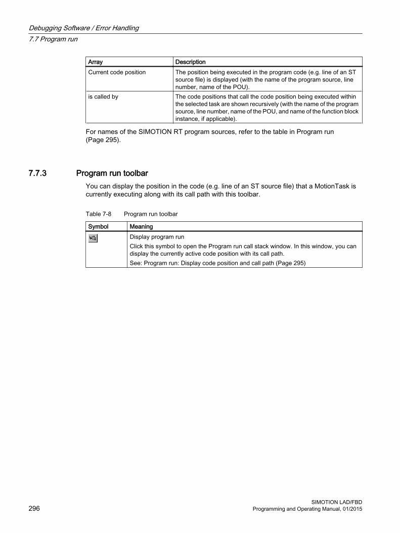
Array DescriptionCurrent code position The position being executed in the program code (e.g. line of an ST
source file) is displayed (with the name of the program source, line number, name of the POU).
is called by The code positions that call the code position being executed within the selected task are shown recursively (with the name of the program source, line number, name of the POU, and name of the function block instance, if applicable).
For names of the SIMOTION RT program sources, refer to the table in Program run (Page 295).
7.7.3 Program run toolbarYou can display the position in the code (e.g. line of an ST source file) that a MotionTask is currently executing along with its call path with this toolbar.
Table 7-8 Program run toolbar
Symbol MeaningDisplay program runClick this symbol to open the Program run call stack window. In this window, you can display the currently active code position with its call path.See: Program run: Display code position and call path (Page 295)
Debugging Software / Error Handling7.7 Program run
SIMOTION LAD/FBD296 Programming and Operating Manual, 01/2015

7.8 Program status (monitoring program execution)
Monitoring the program executionMonitoring the program execution does not affect the actual execution of the program, but does increase the communication load. This has an impact on the execution of MotionTasks and the BackgroundTask.
Program status can be switched on and off during all operating modes of a SIMOTION device (Page 281).
Note
In the process mode, the program status can be called only once for a LAD/FBD program, FB or FC. If you do not observe the restriction, error message 25023 "No resources in the runtime" will appear.
In the test mode, the program status can be called simultaneously for several LAD/FBD programs, FB or FC. The maximum possible number depends on the utilization of the SIMOTION device.
The values of the following variables are displayed:
● Simple data type variables (INT, REAL, etc.)
● Individual elements of a structure, provided an assignment is made
● Individual elements of an array, provided an assignment is made
● Enumeration data type variables
Note
The values of constants are not displayed.
Due to the restricted buffer capacity and the requirement for minimum runtime tampering, the following variables cannot be displayed:● Complete arrays● Complete structures
Individual array elements or individual structure elements are displayed, however, provided an assignment is made in the ST source file.
Debugging Software / Error Handling7.8 Program status (monitoring program execution)
SIMOTION LAD/FBDProgramming and Operating Manual, 01/2015 297
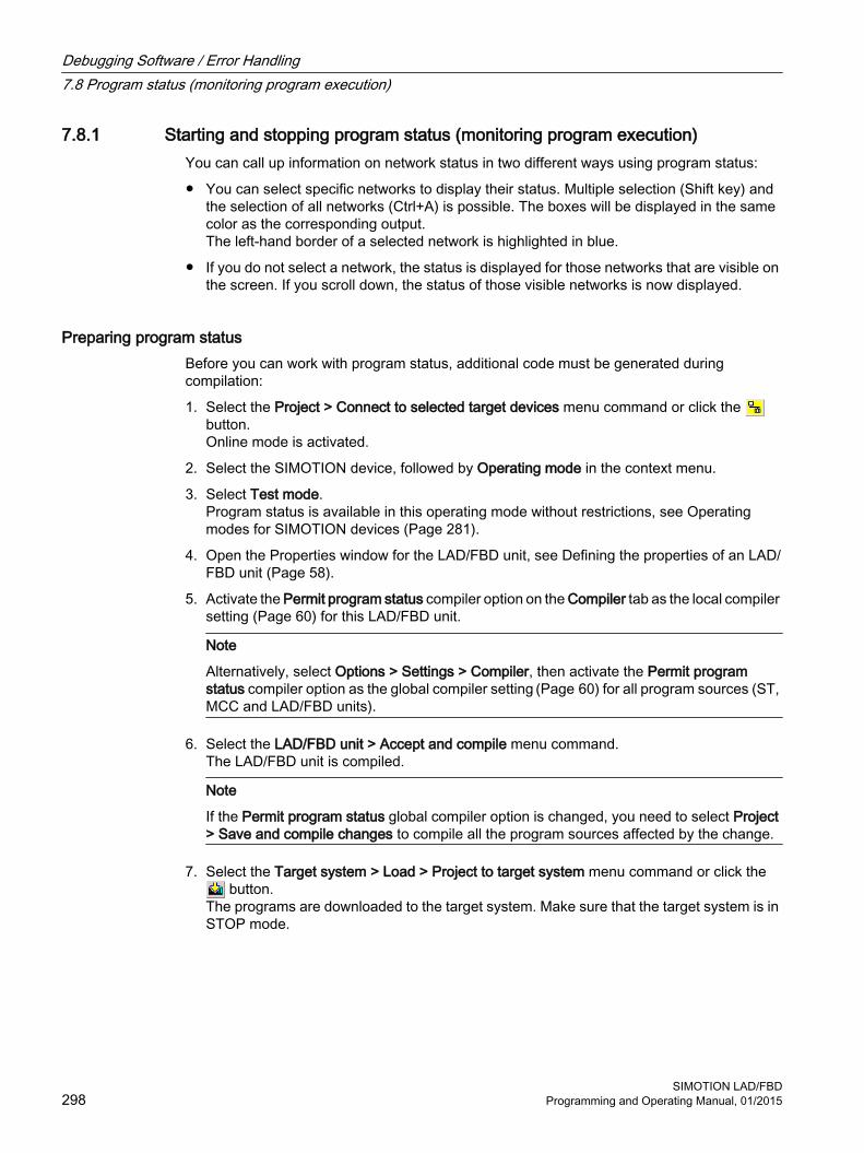
7.8.1 Starting and stopping program status (monitoring program execution)You can call up information on network status in two different ways using program status:
● You can select specific networks to display their status. Multiple selection (Shift key) and the selection of all networks (Ctrl+A) is possible. The boxes will be displayed in the same color as the corresponding output.The left-hand border of a selected network is highlighted in blue.
● If you do not select a network, the status is displayed for those networks that are visible on the screen. If you scroll down, the status of those visible networks is now displayed.
Preparing program statusBefore you can work with program status, additional code must be generated during compilation:
1. Select the Project > Connect to selected target devices menu command or click the button.Online mode is activated.
2. Select the SIMOTION device, followed by Operating mode in the context menu.
3. Select Test mode.Program status is available in this operating mode without restrictions, see Operating modes for SIMOTION devices (Page 281).
4. Open the Properties window for the LAD/FBD unit, see Defining the properties of an LAD/FBD unit (Page 58).
5. Activate the Permit program status compiler option on the Compiler tab as the local compiler setting (Page 60) for this LAD/FBD unit.
Note
Alternatively, select Options > Settings > Compiler, then activate the Permit program status compiler option as the global compiler setting (Page 60) for all program sources (ST, MCC and LAD/FBD units).
6. Select the LAD/FBD unit > Accept and compile menu command.The LAD/FBD unit is compiled.
Note
If the Permit program status global compiler option is changed, you need to select Project > Save and compile changes to compile all the program sources affected by the change.
7. Select the Target system > Load > Project to target system menu command or click the button.
The programs are downloaded to the target system. Make sure that the target system is in STOP mode.
Debugging Software / Error Handling7.8 Program status (monitoring program execution)
SIMOTION LAD/FBD298 Programming and Operating Manual, 01/2015

Starting the Status program
Requirement● The corresponding LAD/FBD program is opened.
● The LAD/FBD program does not contain any unsaved changes.
● The LAD/FBD unit in SCOUT must be consistent with the target system.
ProcedureTo start program status, proceed as follows:
1. Select the LAD/FBD program > Program status on/off menu command or click the button for Program status (Ctrl+F7 shortcut) to start this test mode.
2. If the LAD/FBD program is assigned to more than one task, the Call path/task selection Program status dialog box opens:
– In this dialog box, select the task in which you want to monitor the program.
The symbol on the tab for the open LAD/FBD program indicates that program status has started, as does the symbol for the respective combination of the currently activated test functions (program status, breakpoints).
NoteStart program status for multiple windows for each SIMOTION device
A window can be an open ST source file, an open LAD/FBD program or an open MCC chart. An active window is located in the foreground and the current status values are displayed (MCC: open MCC command).
In Process mode, program status can only be started for one window.
In Test mode, program status can be started simultaneously for several windows per task. The maximum possible number depends on the utilization of the SIMOTION device.
If program status is started for an additional window (Process mode) or starting it causes the maximum possible number to be exceeded (Test mode), program status is automatically deactivated for the currently active window (Process mode) or the oldest active window (Test mode), i.e. momentarily paused, but not stopped. If a window with deactivated program status is brought to the foreground (MCC: open MCC command), program status is automatically reactivated and the current status values are displayed again.
If the program execution monitoring is activated, the ladder diagram lines/signal paths of the selected networks or the networks displayed on the screen are colored according to the current values:
Debugging Software / Error Handling7.8 Program status (monitoring program execution)
SIMOTION LAD/FBDProgramming and Operating Manual, 01/2015 299
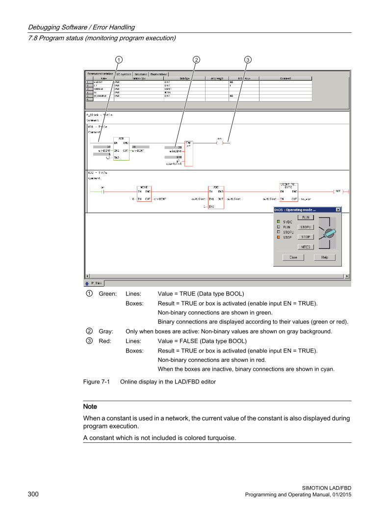
① Green: Lines: Value = TRUE (Data type BOOL)Boxes: Result = TRUE or box is activated (enable input EN = TRUE).
Non-binary connections are shown in green.Binary connections are displayed according to their values (green or red).
② Gray: Only when boxes are active: Non-binary values are shown on gray background.③ Red: Lines: Value = FALSE (Data type BOOL)
Boxes: Result = TRUE or box is activated (enable input EN = TRUE).Non-binary connections are shown in red.When the boxes are inactive, binary connections are shown in cyan.
Figure 7-1 Online display in the LAD/FBD editor
Note
When a constant is used in a network, the current value of the constant is also displayed during program execution.
A constant which is not included is colored turquoise.
Debugging Software / Error Handling7.8 Program status (monitoring program execution)
SIMOTION LAD/FBD300 Programming and Operating Manual, 01/2015

Stopping program statusTo stop program status, proceed as follows:
1. Select the LAD/FBD program > Program status on/off menu command or click the button for Program status (Ctrl+F7 shortcut).Program status is stopped.
Disabling program statusDisabling program status frees up CPU resources.
To disable program status, proceed as follows:
1. First, stop the program status function, see Stopping program status.
2. Open the Properties window for the LAD/FBD unit, see Defining the properties of an LAD/FBD unit (Page 58).
3. Deactivate the Permit program status compiler option on the Compiler tab as the local compiler setting (Page 60) for this LAD/FBD unit and confirm by clicking OK.
Note
If the Permit program status compiler option is activated as the global setting for the compiler (Page 60), you can deactivate this for either one LAD/FBD unit by deactivating the relevant Use global settings checkbox, see Local compiler settings (Page 60) or for all the program sources by selecting Options > Settings > Compiler.
4. Select the SIMOTION device, followed by Operating mode in the context menu.
5. Select Process mode.Program execution is optimized for this operating mode to ensure maximum performance, see Operating modes for SIMOTION devices (Page 281).
6. Recompile the program and download it to the target system.
Note
If the Permit program status global compiler option is changed, you need to select Project > Save and compile changes to compile all the program sources affected by the change.
Debugging Software / Error Handling7.8 Program status (monitoring program execution)
SIMOTION LAD/FBDProgramming and Operating Manual, 01/2015 301

7.9 Breakpoints
7.9.1 General procedure for setting breakpointsYou can set breakpoints within a POU of a program source (e.g. ST source, MCC chart, LAD/FBD source). On reaching an activated breakpoint, the task in which the POU with the breakpoint is called is stopped. If the breakpoint that initiated the stopping of the tasks is located in a program or function block, the values of the static variables for this POU are displayed in the "Variables status" tab of the detail display. Temporary variables (also in/out parameters for function blocks) are not displayed. You can monitor static variables of other POUs or unit variables in the symbol browser.
Requirement:● The program source with the POU (e.g. ST source file, MCC chart, LAD/FBD program) is
open.
ProcedureFollow these steps:
1. Select "Debug mode" for the associated SIMOTION device; see Setting debug mode (Page 303).
2. Specify the tasks to be stopped, see Specifying the debug task group (Page 304).
3. Set breakpoints, see Setting breakpoints (Page 306).
4. Define the call path, see Defining a call path for a single breakpoint (Page 309).
5. Activate the breakpoints, see Activating breakpoints (Page 312).
Debugging Software / Error Handling7.9 Breakpoints
SIMOTION LAD/FBD302 Programming and Operating Manual, 01/2015

7.9.2 Setting the debug mode
WARNING
Dangerous plant states possible
If problems occur in the communication link between the PC and the SIMOTION device, this may result in dangerous plant states (e.g. the axis may start moving in an uncontrollable manner).
Therefore, use the debug mode only with activated life-sign monitoring (Page 283) with a suitably short monitoring time!
You must observe the appropriate safety regulations.
The function is released exclusively for commissioning, diagnostic and service purposes. The function should generally only be used by authorized technicians. The safety shutdowns of the higher-level control have no effect!
Therefore, there must be an EMERGENCY STOP circuit in the hardware. The appropriate measures must be taken by the user.
Requirement1. A connection to the target system must have been established (online mode)
2. Debug mode must not be selected for any SIMOTION device.
ProcedureTo set the debug mode, proceed as follows:
1. Highlight the SIMOTION device in the project navigator.
2. Select Operating mode from the context menu.
3. Select Debug mode (Page 281).
4. Accept the safety information
5. Parameterize the sign-of-life monitoring.See also section: Important information about the life-sign monitoring (Page 283).
6. Confirm with OK.
SIMOTION SCOUT switches to debug mode for this device; the SIMOTION device itself remains in "test mode", as long as at least one breakpoint is activated:
The project navigator indicates that debug mode is activated for SIMOTION SCOUT by means of a symbol next to the SIMOTION device.
The breakpoints toolbar (Page 307) is displayed.
As long as no breakpoints are activated, you can edit program sources in debug mode (Page 286).
Debugging Software / Error Handling7.9 Breakpoints
SIMOTION LAD/FBDProgramming and Operating Manual, 01/2015 303

Debug mode is not enabled for the SIMOTION device until at least one set breakpoint is activated. If all breakpoints are deactivated, debug mode is canceled for the SIMOTION device. The status bar indicates that debug mode is activated for the SIMOTION device.
Note
Pressing the spacebar or switching to a different Windows application causes the following to happen if the SIMOTION device is in debug mode (breakpoints activated):● The SIMOTION device switches to the STOP operating state.● The outputs are deactivated (ODIS).
WARNING
Dangerous plant states possible
This function is not guaranteed in all operating states.
Therefore, there must be an EMERGENCY STOP circuit in the hardware. The appropriate measures must be taken by the user.
7.9.3 Define the debug task groupOn reaching an activated breakpoint, all tasks that are assigned to the debug task group are stopped.
Requirement1. A connection to the target system must have been established (online mode).
2. SIMOTION SCOUT is in debug mode for the corresponding SIMOTION device; see Setting debug mode (Page 303).
ProcedureHow to assign a task to the debug task group:
1. Highlight the relevant SIMOTION device in the project navigator.
2. Select Debug task group from the context menu.The Debug Task group window opens.
3. Select the tasks to be stopped on reaching the breakpoint:
– If you only want to stop individual tasks (in RUN operating state): Activate the Debug task group selection option.Assign all tasks to be stopped on reaching a breakpoint to the Tasks to be stopped list.
– If you only want to stop individual tasks (in HOLD operating state): Activate the All tasks selection option.In this case, also select whether the outputs and technology objects are to be released again after resumption of program execution.
Debugging Software / Error Handling7.9 Breakpoints
SIMOTION LAD/FBD304 Programming and Operating Manual, 01/2015

Note
Note the different behavior when an activated breakpoint is reached, see the following table.
Table 7-9 Behavior at the breakpoint depending on the tasks to be stopped in the debug task group.
Property Tasks to be stoppedSingle selected tasks(debug task group)
All tasks
Behavior on reaching the breakpoint Operating state RUN STOP Stopped tasks Only tasks in the debug task group All tasks Outputs Active Deactivated (ODIS activated) Technology Closed-loop control active No closed-loop control (ODIS activated) Runtime measurement of the
tasksActive for all tasks Deactivated for all tasks
Time monitoring of the tasks Deactivated for tasks in the debug task group
Deactivated for all tasks
Real-time clock Continues to run Continues to runBehavior on resumption of program execution Operating state RUN RUN Started tasks All tasks in the debug task group All tasks Outputs Active The behavior of the outputs and the tech‐
nology objects depends on the 'Continue' activates the outputs (ODIS deactivated) checkbox.● Active: ODIS will be deactivated. All
outputs and technology objects are released.
● Inactive: ODIS remains activated. All outputs and technology objects are only enabled for one STOP-RUN transition.
Technology Closed-loop control active
Note
You can only make changes to the debug task group if no breakpoints are active.
The settings of the debug task group are retained after exiting "Debug mode".
Proceed as follows:1. Set breakpoints (see Setting breakpoints (Page 306)).
2. Define the call path (see Defining a call path for a single breakpoint (Page 309)).
3. Activate the breakpoints (see Activating breakpoints (Page 312)).
Debugging Software / Error Handling7.9 Breakpoints
SIMOTION LAD/FBDProgramming and Operating Manual, 01/2015 305

7.9.4 Setting breakpoints
Requirements: 1. The program source with the POU (e.g. ST source file, MCC chart, LAD/FBD program) is
open.
2. A connection to the target system must have been established (online mode).
3. SIMOTION SCOUT is in debug mode for the corresponding SIMOTION device; see Setting debug mode (Page 303).
4. The tasks to be stopped are specified, see Specifying the debug task group (Page 304).
ProcedureHow to set a breakpoint:
1. Select the code location where no breakpoint has been set:
– SIMOTION ST: Place the cursor on a line in the ST source file that contains a statement.
– SIMOTION MCC: Select an MCC command in the MCC chart (except module or comment block).
– SIMOTION LAD/FBD: Set the cursor in a network of the LAD/FBD program.
2. Perform the following (alternatives):
– Select the Debug > Set/remove breakpoint menu command (shortcut F9).
– Click the button in the Breakpoints toolbar.
To remove a breakpoint, proceed as follows:
1. Select the code position with the breakpoint.
2. Perform the following (alternatives):
– Select the Debug > Set/remove breakpoint menu command (shortcut F9).
– Click the button in the Breakpoints toolbar.
To remove all breakpoints (in all program sources) of the SIMOTION device, proceed as follows:
● Perform the following (alternatives):
– Select the Debug > Remove all breakpoints menu command (shortcut CTRL+F5).
– Click the button in the Breakpoints toolbar.
Debugging Software / Error Handling7.9 Breakpoints
SIMOTION LAD/FBD306 Programming and Operating Manual, 01/2015

Note
You cannot set breakpoints:● For SIMOTION ST: In lines that contain only comment.● For SIMOTION MCC: On the module or comment block commands.● For SIMOTION LAD/FBD: Within a network.● At code locations in which other debug points (e.g. trigger points) have been set.
You can list the debug points in all program sources of the SIMOTION device in the debug table:● Click the button for "debug table" in the Breakpoints toolbar.
In the debug table, you can also remove all breakpoints (in all program sources) of the SIMOTION device:● Click the button for "Clear all breakpoints".
The breakpoints set also remain saved after leaving debug mode; they are displayed in debug mode only.
You can use the program status (Page 298) diagnosis functions and breakpoints together in a program source or POU. However, the following restrictions apply depending on the program languages:
● SIMOTION ST: For version V3.2 of the SIMOTION Kernel, the (marked) ST source file lines to be tested with program status must not contain a breakpoint.
● SIMOTION MCC and LAD/FBD: The commands of the MCC chart (or networks of the LAD/FBD program) to be tested with program status must not contain a breakpoint.
Proceed as follows1. Define the call path, see Defining a call path for a single breakpoint (Page 309).
2. Activate the breakpoints, see Activating breakpoints (Page 312).
7.9.5 Breakpoints toolbarThis toolbar contains important operator actions for setting and activating breakpoints:
Table 7-10 Breakpoints toolbar
Symbol MeaningSet/remove breakpointClick this icon to set at breakpoint for the selected code position or to remove an existing breakpoint.See: Setting breakpoints (Page 306).Activate/deactivate breakpointClick this icon to activate or deactivate the breakpoint at the selected code position.See: Activating breakpoints (Page 312).
Debugging Software / Error Handling7.9 Breakpoints
SIMOTION LAD/FBDProgramming and Operating Manual, 01/2015 307

Symbol MeaningEdit the call pathClick this icon to define the call path for the breakpoints:● If a code position with breakpoint is selected: The call path for this breakpoint.● If a code position without breakpoint is selected: The call path for all breakpoints of
the POU.See: Defining the call path for a single breakpoint (Page 309), Defining the call path for all breakpoints (Page 311).Activate all breakpoints of the active POUClick this symbol to activate all breakpoints in the active program source or POU (e.g. ST source file, MCC chart, LAD/FBD program).See: Activating breakpoints (Page 312).Deactivate all breakpoints of the active POUClick this symbol to deactivate all breakpoints in the active program source or POU (e.g. ST source file, MCC chart, LAD/FBD program).See: Activating breakpoints (Page 312).Remove all breakpoints of the active POUClick this symbol to remove all breakpoints from the active program source or POU (e.g. ST source file, MCC chart, LAD/FBD program).See: Setting breakpoints (Page 306).Debug tableClick this icon to display the debug table.See: Debug table parameters.Display call stackClick this icon after reaching an activated breakpoint to:● View the call path at the current breakpoint.● View the code positions at which the other tasks of the debug task group have been
stopped together with their call path.See: Displaying the call stack (Page 315).ResumeClick this icon to continue the program execution after reaching an activated breakpoint.See: Resuming program execution (Page 315), Displaying the call stack (Page 315).Next step (SIMOTION Kernel as of version V4.4)Only available for the MCC and LAD/FBD programming languages:Click this icon to resume the program execution until the next MCC command or LAD/FBD network is reached.See: Resume program execution in single steps (Page 316).Step through the subprogram (SIMOTION Kernel as of version V4.4)Only available for the MCC programming language.Click this icon to jump to the called subprogram and stop at the first command. The subprogram must be created in the MCC or LAD/FBD programming language.See: Resume program execution in single steps (Page 316).
Debugging Software / Error Handling7.9 Breakpoints
SIMOTION LAD/FBD308 Programming and Operating Manual, 01/2015

7.9.6 Defining the call path for a single breakpoint
Requirements: 1. The program source with the POU (e.g. ST source file, MCC chart, LAD/FBD program) is
open.
2. A connection to the target system must have been established (online mode).
3. SIMOTION SCOUT is in debug mode for the corresponding SIMOTION device; see Setting debug mode (Page 303).
4. The tasks to be stopped are specified, see Specifying the debug task group (Page 304).
5. Breakpoint is set, see Setting breakpoints (Page 306).
ProcedureTo define the call path for a single breakpoint, proceed as follows:
1. Select the code location where a breakpoint has already been set:
– SIMOTION ST: Set the cursor in an appropriate line of the ST source.
– SIMOTION MCC: Select an appropriate command in the MCC chart.
– SIMOTION LAD/FBD: Set the cursor in an appropriate network of the LAD/FBD program.
2. Click the button for "edit call path" in the Breakpoints toolbar.In the Call path / task selection breakpoint window, the marked code position is displayed (with the name of the program source, line number, name of the POU).
3. Select the task in which the user program (i.e. all tasks in the debug task group) will be stopped when the selected breakpoint is reached.The following are available:
– All calling locations starting at this call levelThe user program will always be started when the activated breakpoint in any task of the debug task group is reached.
– The individual tasks from which the selected breakpoint can be reached.The user program will be stopped only when the breakpoint in the selected task is reached. The task must be in the debug task group.The specification of a call path is possible.
Debugging Software / Error Handling7.9 Breakpoints
SIMOTION LAD/FBDProgramming and Operating Manual, 01/2015 309

4. Only for functions and function blocks: Select the call path, i.e. the code position to be called (in the calling POU).The following are available:
– All calling locations starting at this call levelNo call path is specified. The user program is always stopped at the activated breakpoint if the POU in the selected tasks is called.
– Only when a single task is selected: The code positions to be called within the selected task (with the name of the program source, line number, name of the POU).The call path is specified. The user program will be stopped at the activated breakpoint only when the POU is called from the selected code position.If the POU of the selected calling code position is also called from other code positions, further lines are displayed successively in which you proceed similarly.
5. If the breakpoint is only to be activated after the code position has been reached several times, select the number of times.
Note
You can also define the call path to the individual breakpoints in the debug table:1. Click the button for "debug table" in the Breakpoints toolbar.
The "Debug table" window opens.2. Click the appropriate button in the "Call path" column.3. Proceed in the same way as described above:
– Specify the task.– Define the call path (only for functions and function blocks).– Specify the number of passes after which the breakpoint is to be activated.
Proceed as follows:● Activate the breakpoints, see Activating breakpoints (Page 312).
Note
You can use the "Display call stack (Page 315)" function to view the call path at a current breakpoint and the code positions at which the other tasks of the debug task group were stopped.
See alsoDefining the call path for all breakpoints (Page 311)
Debugging Software / Error Handling7.9 Breakpoints
SIMOTION LAD/FBD310 Programming and Operating Manual, 01/2015

7.9.7 Defining the call path for all breakpointsWith this procedure, you can:
● Select a default setting for all future breakpoints in a POU (e.g. MCC chart, LAD/FBD program or POU in an ST source file).
● Accept and compare the call path for all previously set breakpoints in this POU.
Requirements1. The program source with the POU (e.g. ST source file, MCC chart, LAD/FBD program) is
open.
2. A connection to the target system must have been established (online mode).
3. SIMOTION SCOUT is in debug mode for the corresponding SIMOTION device; see Setting debug mode (Page 303).
4. The tasks to be stopped are specified, see Specifying the debug task group (Page 304).
ProcedureTo define the call path for all future breakpoints of a POU, proceed as follows:
1. Select the code location where no breakpoint has been set:
– SIMOTION ST: Set the cursor in an appropriate line of the ST source.
– SIMOTION MCC: Select an appropriate command in the MCC chart.
– SIMOTION LAD/FBD: Set the cursor in an appropriate network of the LAD/FBD program.
2. Click the button for "edit call path" in the Breakpoints toolbar.In the "Call path / task selection all breakpoints for each POU" window, the marked code position is displayed (with the name of the program source, line number, name of the POU).
3. Select the task in which the user program (i.e. all tasks in the debug task group) will be stopped when a breakpoint in this POU is reached.The following are available:
– All calling locations starting at this call levelThe user program will always be started when an activated breakpoint of the POU in any task of the debug task group is reached.
– The individual tasks from which the selected breakpoint can be reached.The user program will be stopped only when a breakpoint in the selected task is reached. The task must be in the debug task group.The specification of a call path is possible.
Debugging Software / Error Handling7.9 Breakpoints
SIMOTION LAD/FBDProgramming and Operating Manual, 01/2015 311

4. Only for functions and function blocks: Select the call path, i.e. the code position to be called (in the calling POU).The following are available:
– All calling locations starting at this call levelNo call path is specified. The user program is always stopped at an activated breakpoint when the POU in the selected tasks is called.
– Only when a single task is selected: The code positions to be called within the selected task (with the name of the program source, line number, name of the POU).The call path is specified. The user program will be stopped at an activated breakpoint only when the POU is called from the selected code position.If the selected calling code position is in turn called by other code positions, further lines are displayed successively in which you proceed similarly.
5. If a breakpoint is only to be activated after the code position has been reached several times, select the number of times.
6. If you want to accept and compare this call path for all previously set breakpoints in this POU:
– Click Accept.
Proceed as follows:● Activate the breakpoints, see Activating breakpoints (Page 312).
Note
You can use the "Display call stack (Page 315)" function to view the call path at a current breakpoint and the code positions at which the other tasks of the debug task group were stopped.
See alsoDefining the call path for a single breakpoint (Page 309)
7.9.8 Activating breakpointsBreakpoints must be activated if they are to have an effect on program execution.
Requirements1. The program source with the POU (e.g. ST source file, MCC chart, LAD/FBD program) is
open.
2. A connection to the target system must have been established (online mode).
3. SIMOTION SCOUT is in debug mode for the corresponding SIMOTION device; see Setting debug mode (Page 303).
4. The tasks to be stopped are specified, see Specifying the debug task group (Page 304).
Debugging Software / Error Handling7.9 Breakpoints
SIMOTION LAD/FBD312 Programming and Operating Manual, 01/2015

5. Breakpoints are set, see Setting breakpoints (Page 306).
6. Call paths are defined, see Defining a call path for a single breakpoint (Page 309).
Activating breakpointsHow to activate a single breakpoint:
1. Select the code location where a breakpoint has already been set:
– SIMOTION ST: Set the cursor in an appropriate line of the ST source file.
– SIMOTION MCC: Select an appropriate command in the MCC chart.
– SIMOTION LAD/FBD: Set the cursor in an appropriate network of the LAD/FBD program.
2. Perform the following (alternatives):
– Select the Debug > Activate/deactivate breakpoint menu command (shortcut F12).
– Click the button in the Breakpoints toolbar.
To activate all breakpoints (in all program sources) of the SIMOTION device, proceed as follows:
● Perform the following (alternatives):
– Select the Debug > Activate all breakpoints menu command.
– Click the button in the Breakpoints toolbar.
Once the first breakpoint has been activated, the SIMOTION device switches to debug mode. It remains in this mode until the last breakpoint is deactivated.
In the Task status function bar, (Page 317) the tasks with activated breakpoints are highlighted in gray ( ).
Note
Breakpoints of all program sources of the SIMOTION device can also be activated and deactivated in the debug table:1. Click the button for "debug table" in the Breakpoints toolbar.
The "Debug Table" window opens.2. Perform the action below, depending on which breakpoints you want to activate or
deactivate:– Single breakpoints: Check or clear the corresponding checkboxes.– All breakpoints (in all program sources): Click the corresponding button.
The following applies up to version V4.3 of the SIMOTION Kernel:● In the case of activated breakpoints, the "Single step" test function of the SIMOTION MCC
programming language cannot be used.
The following applies as of version V4.4 of the SIMOTION Kernel:● The "Single step" test function of the SIMOTION MCC programming language is not
available in the Debug mode.
Breakpoints cannot be activate if the control priority is at the axis control panel. Conversely, you cannot fetch the control priority for the axis control panel when a breakpoint activated.
Debugging Software / Error Handling7.9 Breakpoints
SIMOTION LAD/FBDProgramming and Operating Manual, 01/2015 313

Behavior at the activated breakpointOn reaching an activated breakpoint (possibly using the selected call path (Page 309)), all tasks assigned to the debug task group will be stopped. The behavior depends on the tasks in the debug task group and is described in "Defining a debug task group (Page 304)". The breakpoint is highlighted.
In the Task status function bar, (Page 317) the task in which the breakpoint was reached is highlighted in red ( ).
The following applies to the programming languages MCC or LAD/FBD: If the debug task group is stopped by a breakpoint, then the user has the option to change to another task, belonging to the debug task group, in the combo box. Always the breakpoint of the currently selected task is visualized.
If the breakpoint that initiated the stopping of the tasks is located in a program or function block, the values of the static variables for this POU are displayed in the "Variables status" tab of the detail display. Temporary variables (also in/out parameters for function blocks) are not displayed. You can monitor static variables of other POUs or unit variables in the symbol browser (Page 287).
You can use the "Display call stack (Page 315)" function to:
● View the call path at the current breakpoint.
● View the code positions with the call path at which the other tasks of the debug task group have been stopped.
Resuming program executionYou can resume the execution of the stopped tasks, see "Resuming program execution" (Page 315).
As of version V4.4 of the SIMOTION Kernel, you can resume the task in single steps that has been stopped at the activated breakpoint in the MCC and LAD/FBD programming languages, see Resuming program execution in single steps (Page 316).
Deactivate breakpointsTo deactivate a single breakpoint, proceed as follows:
1. Select the code position with the activated breakpoint.
2. Perform the following (alternatives):
– Select the Debug > Activate/deactivate breakpoint menu command (shortcut F12).
– Click the button in the Breakpoints toolbar.
To deactivate all breakpoints (in all program sources) of the SIMOTION device, proceed as follows:
● Perform the following (alternatives):
– Select the Debug > Deactivate all breakpoints menu command.
– Click the button in the Breakpoints toolbar.
Once the last breakpoint has been deactivated, the SIMOTION device switches to "test mode"; SIMOTION SCOUT continues to run in debug mode.
Debugging Software / Error Handling7.9 Breakpoints
SIMOTION LAD/FBD314 Programming and Operating Manual, 01/2015

7.9.9 Display call stackYou can use the "Display call stack" function to:
● View the call path at the current breakpoint.
● View the code positions with the call path at which the other tasks of the debug task group have been stopped.
RequirementThe user program is stopped at an activated breakpoint, i.e. the tasks of the debug task group (Page 304) have been stopped.
ProcedureTo call the "Display call stack" function, proceed as follows:
● Click the button for "display call stack" in the Breakpoints toolbar.The "Breakpoint call stack" dialog opens. The current call path (including the calling task and the number of the set passes) is displayed.The call path cannot be changed.
To use the "Display call stack" function, proceed as follows:
1. Keep the "Breakpoint call stack" dialog open.
2. To display the code position at which the other task was stopped, proceed as follows:
– Select the appropriate task. All tasks of the debug task group can be selected.
The code position, including the call path, is displayed. If the code position is contained in a user program, the program source with the POU (e.g. ST source file, MCC chart, LAD/FBD program) will be opened and the code position marked.
3. How to resume program execution:
– Click the button for "resume" (Ctrl+F8 shortcut) on the Breakpoint toolbar.
When the next activated breakpoint is reached, the tasks of the debug task group will be stopped again. The current call path, including the calling task, is displayed.
4. Click OK to close the "Breakpoint call stack" dialog box.
For names of the SIMOTION RT program sources, refer to the table in "Program run (Page 295)".
7.9.10 Resuming program executionHow to resume program execution:
● Perform the following (alternatives):
– Select the Debug > Continue menu command (shortcut CTRL+F8).
– Click the button on the Breakpoint toolbar (Page 307) to "Continue".
The stopped task is continued until the next active breakpoint is reached.
Debugging Software / Error Handling7.9 Breakpoints
SIMOTION LAD/FBDProgramming and Operating Manual, 01/2015 315

7.9.11 Resuming program execution in single steps (as of Kernel V4.4)This function is available as of SIMOTION Kernel version V4.4.
In the MCC and LAD/FBD programming languages you can resume the task in single steps that was stopped at an activated breakpoint (Page 302).
The current MCC command or the current LAD/FBD network and all stopped tasks of the debug task group are executed.
All tasks that are assigned to the debug task group are stopped at the following MCC command or LAD/FBD network or the next activated breakpoint within the debug task group.
Next stepTo execute the current MCC command or the current LAD/FBD network at which the program has been stopped, proceed as follows:
● Perform the following (alternatives):
– Select the Debug > Next step menu command (shortcut CTRL+F10).
– Click the button for "Next step" in the Breakpoints toolbar (Page 307).
The current MCC command or the current LAD/FBD network is executed. The program is stopped at the following MCC command or the current LAD/FBD network.
A subprogram call is executed without interruption as long as no breakpoint is activated within the subprogram. If a
Stepping through the subprogram (MCC only)If the program execution has been stopped at the "Subprogram call" command in the MCC programming language, you can jump to the subprogram and run through it in single steps. The subprogram must have been created in the MCC or LAD/FBD programming language.
● Perform the following (alternatives):
– Select the Debug > Step through subprogram menu command (shortcut CTRL+SHIFT+F10).
– Click the button on the Breakpoint toolbar (Page 307) to "Step through subprogram".
The appropriate MCC chart or LAD/FBD program is opened and the program execution stopped at the first MCC command or LAD/FBD network.
Note
Stepping is not possible in MCC charts and LAD/FBD programs whose sources are in libraries.
Stepping is not possible in ST source files.
You can only open MCC charts and LAD/FBD programs with know-how protection if you have the required authorization (e.g. password).
Debugging Software / Error Handling7.9 Breakpoints
SIMOTION LAD/FBD316 Programming and Operating Manual, 01/2015

7.10 Task status function barIn a combo box, the Task status function bar displays all tasks of the active SIMOTION device, to which a program is assigned.
They are displayed under the following conditions:
1. SIMOTION SCOUT is in online mode.
2. The affected SIMOTION device is active, e.g.
– In the project navigator, the SIMOTION device or an element in its subtree is selected (such as program source, technology object).
– In the working area, an open window is active that belongs to an element in the subtree of the SIMOTION device.
3. The SIMOTION device is consistent.
A background color highlights the occurrence of specific events in the affected task, see the following table. The task in question is displayed in the combo box of the function bar according to the event priority.
Table 7-11 Meaning of background colors in the Task status function bar
Background color Meaning Priority Cyan The affected task waits for a command at the "Single
step" test function (only for SIMOTION MCC program‐ming language).
Highest
Lowest
Red The affected task is located at a breakpoint (Page 312). Blue In the affected task, the "Single step" test function is
activated (only for SIMOTION MCC programming lan‐guage)
Gray In the affected task, at least 1 breakpoint (Page 312) is activated.
Yellow In the affected task, the "Monitoring" test function is ac‐tivated (only for SIMOTION MCC programming lan‐guage).
White In the affected task, none of the above-mentioned test functions are activated.
Note
A selection of a task in the combo box is only possible:● For the following test functions of the SIMOTION MCC programming language:
– Monitoring– Single step– Trace
● at activated breakpoints (Page 312) in the MCC or LAD/FBD programming languages.
Debugging Software / Error Handling7.10 Task status function bar
SIMOTION LAD/FBDProgramming and Operating Manual, 01/2015 317

7.11 Project comparisonSIMOTION SCOUT has a project comparison function (start this via the Start object comparison
button) for comparing objects within the same project and/or objects from different projects (online or offline).
Project comparison allows you to establish any differences and, if necessary, run a data transfer to rectify them.
Objects are devices and their sub-objects, programs, technology objects (TOs) or drive objects (DOs), and libraries. Comparing projects is useful if you need to carry out service work on the system.
Further information on project and detail comparisons can be found in the SIMOTION Project Comparison Function Manual.
Debugging Software / Error Handling7.11 Project comparison
SIMOTION LAD/FBD318 Programming and Operating Manual, 01/2015
Application Examples 88.1 Examples
You will be given an introduction to the LAD and FBD programming languages using two simple examples.
SIMOTION LAD/FBDProgramming and Operating Manual, 01/2015 319

8.2 Creating sample programs
Requirements for program creationThe project is the highest level in the data management hierarchy. SIMOTION SCOUT saves all data which belongs, for example, to a production machine, in the project directory.
This means that the project therefore brackets together all SIMOTION devices, drives, etc., belonging to one machine.
Within the project, the hardware used must be made known to the system, including:
● SIMOTION device
● Centralized I/O (with I/O addresses)
● Distributed I/O (with I/O addresses)
A SIMOTION device must be configured before you can insert and edit LAD/FBD sources.
Sample programsWe will create two short programs (position blinker program, axis program) that demonstrate all the work steps from the creation through to the start and testing of a program.
Application Examples8.2 Creating sample programs
SIMOTION LAD/FBD320 Programming and Operating Manual, 01/2015

8.3 Blinker program
PrerequisitesA project must have been created and the hardware used in the project must be known to the system.
Task specificationOutput of a cyclically changing bit pattern after exceeding a limit value.
This task is divided into the following parts:
● Insert LAD/FBD source file
● Insert LAD/FBD programNetwork oneA program variable is incremented and compared to a reference valueNetwork twoWhen the reference value is exceeded, the program variable is reset and a bit pattern is output
● Compiling
● Insert program in a task
● Download program onto target device
You can observe the result of your program at the outputs of your target system.
This example deals only with the LAD programming aspect.
Application Examples8.3 Blinker program
SIMOTION LAD/FBDProgramming and Operating Manual, 01/2015 321

8.3.1 Insert LAD/FBD source fileTo insert a new LAD/FBD unit using the context menu:
1. Select the PROGRAMS folder of the relevant SIMOTION device in the project navigator.
2. Double-click the entry Insert LAD/FBD unit.
Figure 8-1 Project folder
The Insert LAD/FBD Unit dialog box appears.
Application Examples8.3 Blinker program
SIMOTION LAD/FBD322 Programming and Operating Manual, 01/2015

Figure 8-2 Insert LAD/FBD Unit dialog box
3. Enter the name of the LAD/FBD unit.The names of program sources must comply with the rules for identifiers (Page 99): They are made up of letters (A … Z, a … z), numbers (0 … 9), or single underscores (_) in any order, whereby the first character must be a letter or underscore. No distinction is made between upper- and lower-case letters.The permissible length of the name depends on the SIMOTION Kernel version:
– SIMOTION Kernel as of version V4.1: Maximum 128 characters.
– SIMOTION Kernel up to version V4.0: Maximum 8 characters.
Names must be unique within the SIMOTION device. Protected or reserved identifiers (Page 362) are not permitted.Existing program sources (e.g. LAD/FBD units, ST source files) are displayed.
4. Activate the Permit program status compiler option to be able to use the online status display later:
– Deactivate the associated checkbox in the "Global settings" column.
– Activate the associated checkbox in the "Current settings" column.
5. In the Compiler tab, activate the Permit program status checkbox
6. You can also enter an author, version, and a comment.
Application Examples8.3 Blinker program
SIMOTION LAD/FBDProgramming and Operating Manual, 01/2015 323

7. Activate the Open editor automatically checkbox.
8. Confirm with OK.The declaration tables for exported and source-internal variables appear in the working area.No variables are defined here in the sample program.
Figure 8-3 Declaration tables for exported and source-internal declarations
Application Examples8.3 Blinker program
SIMOTION LAD/FBD324 Programming and Operating Manual, 01/2015

8.3.2 Insert LAD/FBD programTo insert an LAD/FBD program, proceed as follows:
1. In the PROGRAMS folder in the project navigator, open the LAD/FBD unit you just inserted.
2. Double-click the entry Insert LAD/FBD program in the LAD/FBD unit.
Figure 8-4 Opening a project folder
The Insert LAD/FBD Program dialog box appears.
Application Examples8.3 Blinker program
SIMOTION LAD/FBDProgramming and Operating Manual, 01/2015 325
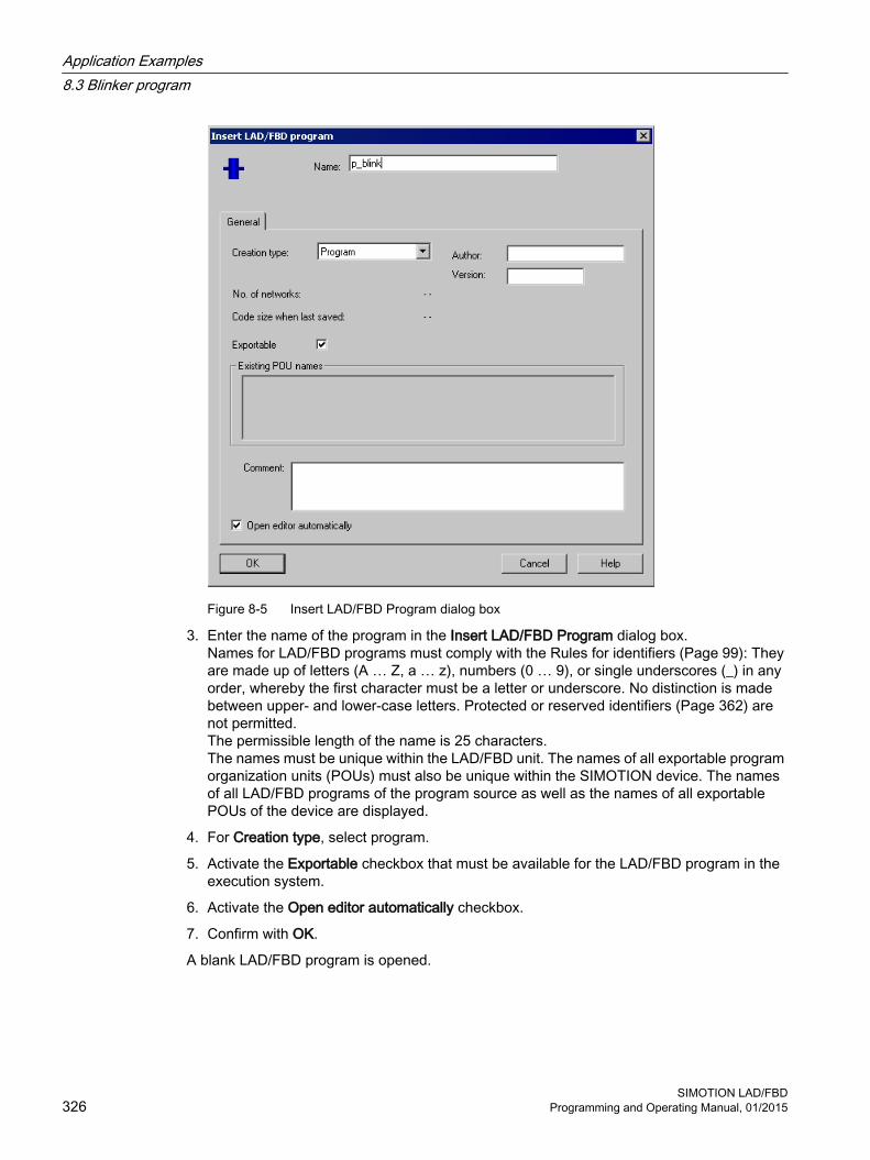
Figure 8-5 Insert LAD/FBD Program dialog box
3. Enter the name of the program in the Insert LAD/FBD Program dialog box.Names for LAD/FBD programs must comply with the Rules for identifiers (Page 99): They are made up of letters (A … Z, a … z), numbers (0 … 9), or single underscores (_) in any order, whereby the first character must be a letter or underscore. No distinction is made between upper- and lower-case letters. Protected or reserved identifiers (Page 362) are not permitted.The permissible length of the name is 25 characters.The names must be unique within the LAD/FBD unit. The names of all exportable program organization units (POUs) must also be unique within the SIMOTION device. The names of all LAD/FBD programs of the program source as well as the names of all exportable POUs of the device are displayed.
4. For Creation type, select program.
5. Activate the Exportable checkbox that must be available for the LAD/FBD program in the execution system.
6. Activate the Open editor automatically checkbox.
7. Confirm with OK.
A blank LAD/FBD program is opened.
Application Examples8.3 Blinker program
SIMOTION LAD/FBD326 Programming and Operating Manual, 01/2015

Figure 8-6 Open LAD/FBD program
8.3.3 Entering variables in the declaration tableTo enter variables, proceed as follows:
1. Select the Parameters/variables tab.
2. Enter name, variable type, data type and/or start value in the declaration table (as shown in the figure below).
Figure 8-7 Variables in the declaration table
Application Examples8.3 Blinker program
SIMOTION LAD/FBDProgramming and Operating Manual, 01/2015 327

3. Select the I/O Symbols tab.
4. Enter the name and absolute identifier (in accordance with the figure below).The data type is entered automatically.
Figure 8-8 I/O symbols in the declaration table
8.3.4 Entering a program titleTo enter a program title, proceed as follows:
1. Click in the title line.
2. Enter the program name in the window.
Figure 8-9 Program title
8.3.5 Inserting networkTo paste in a network:
1. Select LAD/FBD program > Insert network.
Figure 8-10 Menu selection
2. Click in the title line.
Application Examples8.3 Blinker program
SIMOTION LAD/FBD328 Programming and Operating Manual, 01/2015
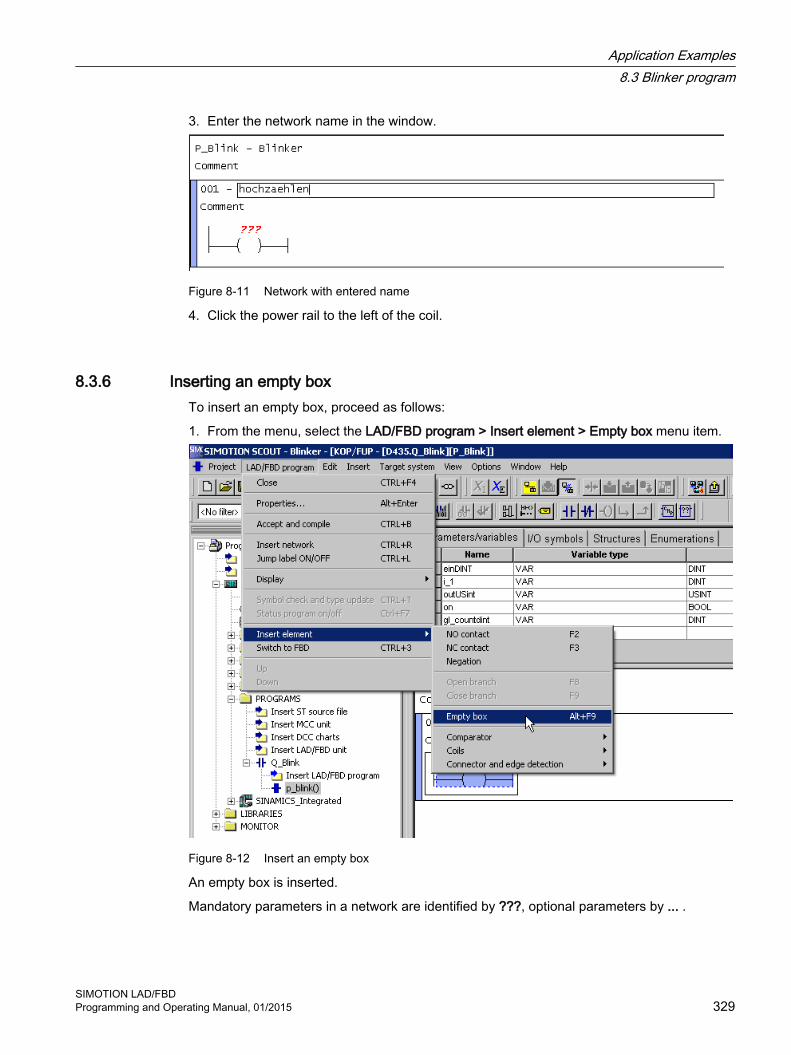
3. Enter the network name in the window.
Figure 8-11 Network with entered name
4. Click the power rail to the left of the coil.
8.3.6 Inserting an empty boxTo insert an empty box, proceed as follows:
1. From the menu, select the LAD/FBD program > Insert element > Empty box menu item.
Figure 8-12 Insert an empty box
An empty box is inserted.
Mandatory parameters in a network are identified by ???, optional parameters by ... .
Application Examples8.3 Blinker program
SIMOTION LAD/FBDProgramming and Operating Manual, 01/2015 329

8.3.7 Selecting box type
Figure 8-13 Empty box
To select a box type, proceed as follows:
1. Press the Enter key in the selected empty box.A drop-down menu appears.
2. Select the ADD box type from the drop-down menu and confirm your selection by pressing the Enter key.
Application Examples8.3 Blinker program
SIMOTION LAD/FBD330 Programming and Operating Manual, 01/2015

Figure 8-14 Selection of box type
Application Examples8.3 Blinker program
SIMOTION LAD/FBDProgramming and Operating Manual, 01/2015 331

8.3.8 Parameterizing the ADD call-upTo parameterize the ADD call-up, proceed as follows:
1. Click in the other mandatory input fields ???.
Figure 8-15 ADD box
2. Enter the appropriate values.
Figure 8-16 Parameterized ADD box
Application Examples8.3 Blinker program
SIMOTION LAD/FBD332 Programming and Operating Manual, 01/2015

8.3.9 Inserting comparatorTo insert a comparator, proceed as follows:
1. Select the ADD box.
Figure 8-17 Selected ADD box
2. Select LAD/FBD program > Insert element >Comparator > > =.
Figure 8-18 Select comparator
Application Examples8.3 Blinker program
SIMOTION LAD/FBDProgramming and Operating Manual, 01/2015 333

Figure 8-19 Inserted comparator
8.3.10 Labeling the comparatorTo label the comparator, proceed as follows:
1. Click each comparator input field individually.
2. Enter the appropriate values for the comparator.
Figure 8-20 Labeled comparator
Application Examples8.3 Blinker program
SIMOTION LAD/FBD334 Programming and Operating Manual, 01/2015

8.3.11 Initializing a coilTo initialize a coil, proceed as follows:
1. Click in the input field ??? of the coil.
2. Enter the appropriate variable.
Figure 8-21 Initialized coil
8.3.12 Inserting next networkTo paste in another network, proceed as follows:
1. To paste in the second network, repeat the steps used to paste in the first network.
Figure 8-22 Project with two networks
Application Examples8.3 Blinker program
SIMOTION LAD/FBDProgramming and Operating Manual, 01/2015 335
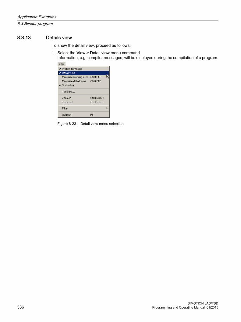
8.3.13 Details viewTo show the detail view, proceed as follows:
1. Select the View > Detail view menu command.Information, e.g. compiler messages, will be displayed during the compilation of a program.
Figure 8-23 Detail view menu selection
Application Examples8.3 Blinker program
SIMOTION LAD/FBD336 Programming and Operating Manual, 01/2015

8.3.14 CompilingTo compile the created program, proceed as follows:
1. Select the program in the project navigator.
2. Open the LAD/FBD program menu and select Accept and compile.The source file and its POUs are saved and compiled.During the compilation process, messages on the successful compilation status are displayed in the detail view. Should any error occur during compilation, they will be displayed in plain text there.
Figure 8-24 Save and compile menu selection
Application Examples8.3 Blinker program
SIMOTION LAD/FBDProgramming and Operating Manual, 01/2015 337

Figure 8-25 Compiled project with compiler information in the detail view
8.3.15 Assigning a sample program to an execution levelTo assign a program to an execution level, proceed as follows:
1. Double-click the EXECUTION SYSTEM folder in the project navigator.
2. Click BackgroundTask.
3. Click the Program assignment tab.
4. Select the program Q_blink.p_blink.
Application Examples8.3 Blinker program
SIMOTION LAD/FBD338 Programming and Operating Manual, 01/2015

5. Click the button >>.
Figure 8-26 Assigning a program to the BackgroundTask
6. Click Close and acknowledge the message saying the execution system has changed by clicking Yes.The changes are accepted into the project.
8.3.16 Starting sample programTo start a program, proceed as follows:
1. Make sure the LAD/FBD unit creates the additional debug code for program status during compilation:Open the Properties window for the LAD/FBD unit (see Defining the properties of an LAD/FBD unit (Page 58)).
2. Activate the Permit program status compiler option on the Compiler tab as the local compiler setting (see Local compiler settings (Page 60)) for this LAD/FBD unit.See also the description relating to Effectiveness of local or global compiler settings (see the SIMOTION ST Programming and Operating Manual).
Application Examples8.3 Blinker program
SIMOTION LAD/FBDProgramming and Operating Manual, 01/2015 339

3. Select Project > Save and recompile all.The project is locally saved on the hard disk and compiled.
4. Select the Project > Connect to selected target devices menu command or click .Online mode is activated.
5. Select the Target system > Load > Download project to target system menu command or click .The project data (including the sample program) and the data of the hardware configuration are downloaded to the RAM of the target system.
6. Select both networks and click the button for program status (Ctrl+F7 shortcut) in the LAD editor function bar (Page 30).Monitoring the program execution (Page 297) is switched on.
7. Mark the SIMOTION device in the project navigator and select Target device > Operating mode in the context menu.The Operating mode window with the software switch for modes opens.
8. Click the RUN button in the software switch.The SIMOTION device is in RUN mode. The sample program is run and the current paths/signal paths are color-coded in accordance with the current signal values (Page 297).
Figure 8-27 Sample program is started
Application Examples8.3 Blinker program
SIMOTION LAD/FBD340 Programming and Operating Manual, 01/2015

8.4 Position axis program
RequirementsA project must be created. In the project, a CPU and a virtual position axis must be created (name of the axis: posAxis).
Task specificationAn axis is to be traversed at a velocity of 10 mm/s from the current position 100 mm in the negative direction.
This task is divided into the following parts:
● Insert LAD/FBD unit
● Insert LAD/FBD program
– Insert network
– Set axis enable signals
– Traverse axis to position
– Remove axis enable
● Compile program
● Insert program in a task
● Download program onto target device
PLCopen blocks are used for the programming. The PLCopen blocks are designed for use in cyclic programs/tasks and enable motion control programming in a PLC environment. They are used primarily in the LAD/FBD programming language.
PLCopen blocks are available as standard functions (directly from the command library).
You can find further information about PLCopen blocks in the SIMOTION PLCopen Blocks Function Manual.
There is a TO-specific command available for the aforementioned subtasks Set axis enable and Traverse axis to position/Remove axis enable. Each command is represented by a box in LAD/FBD. The parameters for individual commands (position = 100, speed = 10 etc.) are entered
via the Variable declaration dialog box.
- or -
via the Enter call parameters dialog box
- or -
by entering the values in the input fields on each connector.
The task is implemented using LAD programming.
Application Examples8.4 Position axis program
SIMOTION LAD/FBDProgramming and Operating Manual, 01/2015 341

8.4.1 Insert LAD/FBD source fileTo insert an LAD/FBD unit (for details of how to insert the unit and program, see also the blinker program (Page 321) example), proceed as follows:
1. Open the PROGRAMS folder of the relevant SIMOTION device in the project navigator.
2. Double-click the entry Insert LAD/FBD unit.The Insert LAD/FBD Unit dialog box appears.
3. Enter the name of the LAD/FBD unit.The names of program sources must comply with the rules for identifiers (Page 99): They are made up of letters (A … Z, a … z), numbers (0 … 9), or single underscores (_) in any order, whereby the first character must be a letter or underscore. No distinction is made between upper- and lower-case letters.The permissible length of the name depends on the SIMOTION Kernel version:
– SIMOTION Kernel as of version V4.1: Maximum 128 characters.
– SIMOTION Kernel up to version V4.0: Maximum 8 characters.
Names must be unique within the SIMOTION device. Protected or reserved identifiers (Page 362) are not permitted. Existing program sources (e.g. ST source files, MCC units) are displayed.
4. In the Compiler tab, activate the Permit program status checkbox, to use the online status display later.
5. You can also enter an author, version, and a comment.
6. Activate the Open editor automatically checkbox.
7. Confirm with OK.The declaration tables for global and unit-local variables appear in the working area.
8.4.2 Insert LAD/FBD programTo insert an LAD/FBD program, proceed as follows:
1. In the PROGRAMS folder within the project navigator, open the LAD/FBD unit you just pasted in.
2. Double-click the entry Insert LAD/FBD program in the LAD/FBD unit.The Insert LAD/FBD Program dialog box appears.
3. Enter the name of the program in the Insert LAD/FBD Program dialog box.Names for LAD/FBD programs must comply with the Rules for identifiers (Page 99): They are made up of letters (A … Z, a … z), numbers (0 … 9), or single underscores (_) in any order, whereby the first character must be a letter or underscore. No distinction is made between upper- and lower-case letters. Protected or reserved identifiers (Page 362) are not permitted.The permissible length of the name is 25 characters.The names must be unique within the LAD/FBD unit. The names of all exportable program organization units (POUs) must also be unique within the SIMOTION device. The names of all LAD/FBD programs of the program source as well as the names of all exportable POUs of the device are displayed.
4. For Creation type, select program.
Application Examples8.4 Position axis program
SIMOTION LAD/FBD342 Programming and Operating Manual, 01/2015

5. Activate the Open editor automatically checkbox.
6. Confirm with OK.A blank LAD/FBD program is opened.
7. Click the working area and select LAD/FBD program > Insert network from the menu to paste in a new network.
Figure 8-28 Pasted network
Note
Mandatory parameters in a network are identified by ???, optional parameters by ... .
8. Select the pasted box and select Delete in the context menu.The box is removed from the network.
Figure 8-29 Pasted network without a box
Application Examples8.4 Position axis program
SIMOTION LAD/FBDProgramming and Operating Manual, 01/2015 343

8.4.3 Inserting a TO-specific commandTo insert a TO-specific command, proceed as follows:
1. To enhance the display in the working area, open the shortcut menu of the network and select Display > Mandatory and assigned box parameters.
2. Select the Command library tab in the project navigator.The command groups appear.
3. Click the relevant plus sign to open the PLCopen > SingleAxis command group.
Application Examples8.4 Position axis program
SIMOTION LAD/FBD344 Programming and Operating Manual, 01/2015

4. Drag and drop the _MC_Power command into the network (see Network with RET assignment).This command serves to enable the command.
Figure 8-30 TO-specific command (_MC_Power) from the command library
Figure 8-31 Network with inserted _MC_Power Box
5. Mark the network and select LAD/FBD program > Insert network from the menu to insert a second network.
Application Examples8.4 Position axis program
SIMOTION LAD/FBDProgramming and Operating Manual, 01/2015 345

6. Mark the inserted box from the second network and select Delete in the context menu.The box is removed from the network.
7. Drag and drop the _MC_MoveRelative command from the command library to the marked position in the second network.The axis is positioned at the specified speed with this command.
Figure 8-32 TO-specific command (_MC_MoveRelative) from the command library
Application Examples8.4 Position axis program
SIMOTION LAD/FBD346 Programming and Operating Manual, 01/2015

Figure 8-33 Network with inserted _MC_MoveRelative box
8.4.4 Connecting the enable inputsThe enable input for the _MC_Power command and the execute enable input for the _MC_MoveRelative command still have to be connected to NO contacts.
How to insert the NO contacts:
1. Click in the working area and select Display > All box parameters in the context menu.All the inputs and outputs of the boxes are shown.
2. Select the Command library tab in the project navigator.The command groups appear.
3. Click the plus symbol to open the command group LAD elements.
Application Examples8.4 Position axis program
SIMOTION LAD/FBDProgramming and Operating Manual, 01/2015 347
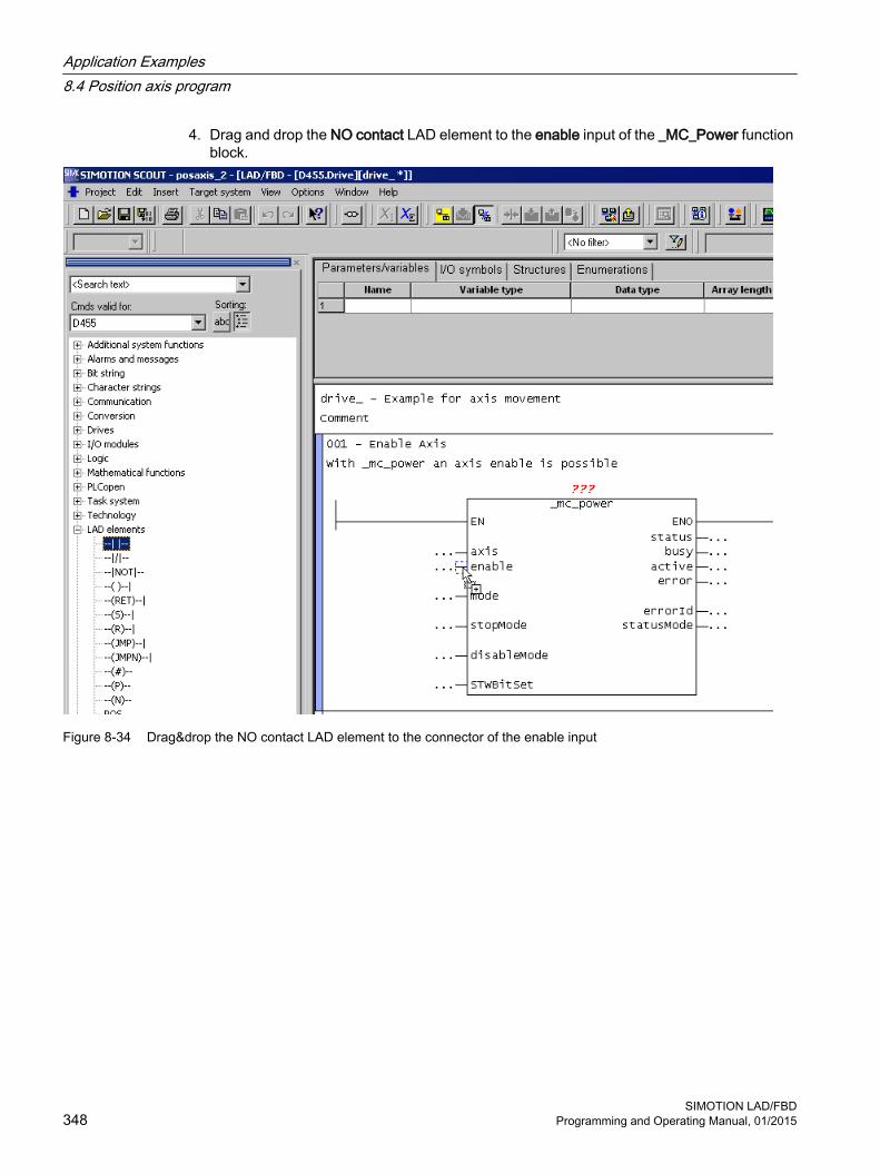
4. Drag and drop the NO contact LAD element to the enable input of the _MC_Power function block.
Figure 8-34 Drag&drop the NO contact LAD element to the connector of the enable input
Application Examples8.4 Position axis program
SIMOTION LAD/FBD348 Programming and Operating Manual, 01/2015

Figure 8-35 Network with a NO contact LAD element inserted
5. Drag and drop two NO contact LAD elements to the execute enable input of the _MC_MoveRelative function block.
Application Examples8.4 Position axis program
SIMOTION LAD/FBDProgramming and Operating Manual, 01/2015 349

Figure 8-36 Networks with NO contacts inserted
Application Examples8.4 Position axis program
SIMOTION LAD/FBD350 Programming and Operating Manual, 01/2015

8.4.5 Entering variables in the declaration tableTo enter variables, proceed as follows:
1. Select the Parameters/variables tab.
2. Enter name, variable type, data type and/or start value in the declaration table (as shown in the figure below).In order to use PLCopen blocks, you must create one instance for each the used blocks (_MC_Power and _MC_MoveRelative). The data type of the instance corresponds to the block name. The variables i_mc_power and i_mc_moverelative are instance variables for the two function blocks _MC_Power and _MC_MoveRelative.You can find further information about the declaration and use of instance variables in Example: Function block (FB) (Page 175).
Figure 8-37 Variables in the declaration table
8.4.6 Parameterization of the NO contactsHow to parameterize each of the NO contacts:
1. Click in the input field ??? for the NO contact.
2. Enter the appropriate variable.
3. Press Enter.
Application Examples8.4 Position axis program
SIMOTION LAD/FBDProgramming and Operating Manual, 01/2015 351
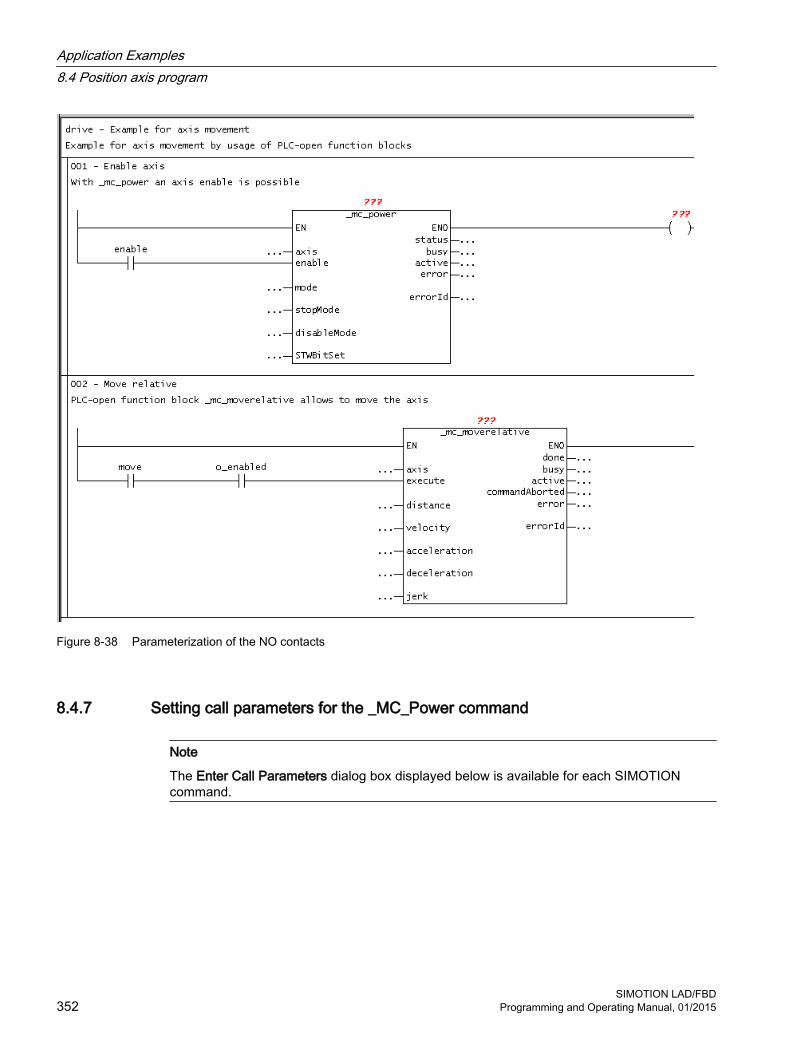
Figure 8-38 Parameterization of the NO contacts
8.4.7 Setting call parameters for the _MC_Power command
Note
The Enter Call Parameters dialog box displayed below is available for each SIMOTION command.
Application Examples8.4 Position axis program
SIMOTION LAD/FBD352 Programming and Operating Manual, 01/2015

To set the call parameters, proceed as follows:
1. Double-click the box.
2. Select the instance, the homing axis, the axis enables to be set, stop mode and enable mode for the axis.If you print the project, your parameters appear in the printout according to your settings, e.g. only allocated box parameters.
3. Confirm with OK.
Figure 8-39 Set call parameters for the PLCopen block _MC_Power
Application Examples8.4 Position axis program
SIMOTION LAD/FBDProgramming and Operating Manual, 01/2015 353

Figure 8-40 Labelled _MC_Power box
Application Examples8.4 Position axis program
SIMOTION LAD/FBD354 Programming and Operating Manual, 01/2015

8.4.8 Setting call parameters for the _MC_MoveRelative commandTo set the call parameters, proceed as follows:
1. Double-click the _mc_moverelative box.
2. Select the instance and the homing axis. Enter values for the difference in distance traveled and for the maximum speed of the axis.If you print the project, your parameters appear in the printout according to your settings, e.g. only allocated box parameters.
3. Confirm with OK.
Figure 8-41 Set call parameters for the PLCopen block _MC_MoveRelative
Application Examples8.4 Position axis program
SIMOTION LAD/FBDProgramming and Operating Manual, 01/2015 355

Figure 8-42 Network with entered variables
8.4.9 Details viewTo show the detail view, proceed as follows:
1. Select the View > Detail view menu item.Information, e.g. compiler messages, will be displayed during the compilation of a program.
8.4.10 CompilingTo compile the program, proceed as follows:
1. Select the program in project navigation.
2. Open the LAD/FBD program menu and select Accept and compile.
Application Examples8.4 Position axis program
SIMOTION LAD/FBD356 Programming and Operating Manual, 01/2015

During the compilation process, messages on the successful compilation status are displayed in the detail view. Should any error occur during compilation, they will be displayed in plain text there.
8.4.11 Assigning a sample program to an execution levelBefore you can run the sample program, you must assign it to an execution level or a task. When you have done this, you can establish the connection to the target system, download the program to the target system, and then start it.
To assign the program to an execution level (see also the blinker program (Page 338) example), proceed as follows:
1. Double-click the EXECUTION SYSTEM folder in the project navigator.
2. Mark the BackgroundTask.
3. Click the Program assignment tab.
4. Select the program.
5. Click the button >>.
6. Click Close.
See alsoAssigning a sample program to an execution level (Page 338)
8.4.12 Starting sample programTo start a program, proceed as follows:
1. Make sure the LAD/FBD unit creates the additional debug code for program status during compilation:Open the Properties window for the LAD/FBD unit (see Defining the properties of an LAD/FBD unit (Page 58)).
2. Activate the Permit program status compiler option on the Compiler tab as the local compiler setting (see Local compiler settings (Page 60)) for this LAD/FBD unit.See also the description relating to Effectiveness of local or global compiler settings (see the SIMOTION ST Programming and Operating Manual).
3. Select Project > Save and recompile all.The project is locally saved on the hard disk and compiled.
4. Select the Project > Connect to selected target devices menu command or click .Online mode is activated.
5. Select the Target system > Load > Download project to target system menu command or click .The project data (including the sample program) and the data of the hardware configuration are downloaded to the RAM of the target system.
Application Examples8.4 Position axis program
SIMOTION LAD/FBDProgramming and Operating Manual, 01/2015 357

6. Select both networks and click the button for program status (CTRL+F7 shortcut) in the LAD editor function bar (Page 30).Monitoring the program execution (Page 298) is switched on.
7. Mark the SIMOTION device in the project navigator and select Target device > Operating mode in the context menu.The Operating mode window with the software switch for modes opens.
8. Click the RUN button in the software switch.The SIMOTION device is in RUN mode. The sample program is run and the current paths/signal paths are color-coded in accordance with the current signal values (Page 298).
Figure 8-43 Sample program is started
Application Examples8.4 Position axis program
SIMOTION LAD/FBD358 Programming and Operating Manual, 01/2015

Appendix AA.1 Key combinations
The following key combinations are available:
With LAD/FBD editor openLeft/right arrow buttonsUp/down arrow buttons
With a selected operator: Navigation between the individual operators
Ctrl+down arrow button Selects previous networkCtrl+up arrow button Selects next networkCtrl+F7 Switches the program status (Page 297) function on and offCtrl+space Automatic completion (Autocomplete) (Page 34) Pg Up Selects the network at the start of the visible editor areaPg Dn Selects the network at the end of the visible editor areaDel Deletes an operatorTab / Shift+Tab Jumps forward to next button / input field / jumps back to previous button / input fieldReturn Opens the input field of the current operand or confirms the entry made in the input fieldEsc Aborts the entry while input field is openShift+F6 Switches between declaration table and editor areaCtrl+Alt+H Opens the symbol input help dialog window
Window menuCtrl+Shift+F5 Rearranges all windows opened in this application in horizontal tiled formatCtrl+Shift+F3 Rearranges all windows opened in this application in vertical tiled formatCtrl+Tab Switches between windows of the working area
View menuCtrl+F11 Maximizes the working areaCtrl+F12 Maximizes the detail viewCtrl+Num+ Enlarges the contents of the working areaCtrl+Num- Reduces the contents of the working areaF5 Updates the view
LAD/FBD unit menuCtrl+F4 Closes the LAD/FBD unitAlt+Enter Displays the properties of the active/selected object for editingCtrl+B Accepts and compiles the active/selected objectCtrl+R Inserts a new network
SIMOTION LAD/FBDProgramming and Operating Manual, 01/2015 359

LAD/FBD program menuCtrl+F4 Closes the LAD/FBD programAlt+Enter Displays the properties of the active/selected object for editingCtrl+B Accepts and compiles the active/selected objectCtrl+R Inserts a new networkCtrl+L Jump label ON/OFFCtrl+Shift+K Shows/hides the comment lineCtrl+Shift+B Display options for boxesCtrl+T Symbol check and type updateCtrl+F7 Program status On/OffAlt+Shift+F8 Inserts a comparatorAlt+Shift+F9 Inserts an empty boxCtrl+1 Switches to LADCtrl+3 Switches to FBD
Edit menuCtrl+Z Undoes the last action (except: Save)Ctrl+Y Redoes the last action which was undoneCtrl+X Cuts a commandCtrl+C Copies a commandCtrl+V Inserts a commandDel Deletes selected commands in the LAD editorF2 Renames the active/selected objectAlt+Enter Displays the properties of the active/selected object for editingCtrl+Alt+O Opens the selected objectCtrl+A Selects all objects in the current windowCtrl+F Local searchCtrl+Shift+F Find in the projectF3 Find next (for local search)Ctrl+H Local find and replaceCtrl+Shift+G Find and replace in a projectCtrl+J Next position (for search in the project)
Debug menuF12 Activates or deactivates a set breakpointCtrl+F8 Continues the program execution at the activated breakpointCtrl+F10 Next step
LAD elementsShift+F2 Inserts an NO contactShift+F3 Inserts an NC contact
AppendixA.1 Key combinations
SIMOTION LAD/FBD360 Programming and Operating Manual, 01/2015

LAD elementsShift+F7 Inserts a coilShift+F8 Opens a branchShift+F9 Closes a branch
FBD elementsShift+F2 Inserts an AND boxShift+F3 Inserts an OR boxShift+F4 Inserts an XOR boxShift+F7 Assignment or jumpShift+F8 Inserts a binary inputShift+F9 Negates a binary input
AppendixA.1 Key combinations
SIMOTION LAD/FBDProgramming and Operating Manual, 01/2015 361

A.2 Protected and reserved identifiersReserved identifiers may only be used as predefined. You may not declare a variable or data type with the name of a reserved identifier.
There is no distinction between upper and lower case notation.
The ST programming language includes protected and reserved identifiers (see the SIMOTION ST Programming and Operating Manual). The same list also applies to the LAD/FBD programming languages. The LAD/FBD programming language also includes the protected and reserved identifiers listed in the table.
You can find a list of all the identifiers whose meanings are predefined in SIMOTION in the SIMOTION Basic Functions Function Manual.
Table A-1 Protected identifiers applicable only to the LAD/FBD programming language
AANDN CCALCALC
CALCN
JJMPJMPC
JMPCN
LLD LDNOORN RRETRETC
RETCN
SST STNXXORN
AppendixA.2 Protected and reserved identifiers
SIMOTION LAD/FBD362 Programming and Operating Manual, 01/2015

Index
--1.#IND, 291-1.#INF, 289, 291-1.#QNAN, 289, 291
__AdditionObjectType, 111_CamTrackType, 110_ControllerObjectType, 111_device, 161_direct, 137, 142, 161_FixedGearType, 111_FormulaObjectType, 111_getcommandid
Advance signal switching, 184_getSafeValue
Application, 161_PathAxis, 111_PathObjectType, 111_quality, 148, 164_SensorType, 111_setSafeValue
Application, 161
11.#IND, 2891.#INF, 289, 2911.#QNAN, 289, 291
AActivating
Automatic symbol check, 41Type update, 41
Advance signal switching_getcommandid, 184Boolean, 184Non-Boolean, 184
Advance switching, 184AND box, 219ANY, 107ANY_BIT, 107ANY_DATE, 107
ANY_ELEMENTARY, 107ANY_INT, 107ANY_NUM, 107ANY_REAL, 107ANYOBJECT, 111Arithmetic operators, 254Array element
Initial value, 100Initialization value, 100Variables, 99
Assignment, 223Resetting, 225Setting, 225
Autocomplete, 34Automatic completion, 34Automatic symbol check
activating, 41Deactivating, 43LAD/FBD editor, 38
Automatic syntax checkLAD/FBD elements, 86
AvailabilityI/O variable, 148
BBackward compatibility, 68Binary input
Inserting, 221Negate, 222
Bit data types, 104, 236BOOL, 104Boolean advance signal switching, 184Box type
Interface adjustment, 185Selecting, 330
Breakpoint, 302Activating, 312Call path, 309, 311Call stack, 315Deactivating, 314remove, 306Setting, 306Toolbar, 307
BYTE, 104
SIMOTION LAD/FBDProgramming and Operating Manual, 01/2015 363
CCall parameters
Making individual settings for LAD/FBD elements, 89Making settings for LAD/FBD elements, 90, 353, 355
Call pathBreakpoint, 309, 311Call stack, 315Program run, 295
CamType, 111Change
Colors, 45Fonts, 45LAD/FBD program creation type, 71
CloseLAD/FBD program, 68LAD/FBD unit, 52
Close parallel branch, 217Code attributes, 195Colors
Changing, 45Command call
Drag-and-drop, 33Command library, 92
Pasting in functions, 93Pasting in LAD/FBD elements, 93Special features, 95
Command nameDrag-and-drop, 33
CommentPrint, 73
CommissioningExecution levels and tasks, 276
Commissioning (software)Assigning programs to a task, 274Downloading the project to the target system, 279Task start sequence, 278
Comparator, 232Comparison operations
Comparator, 232Overview, 232
CompilerGlobal settings, 60Local settings, 60
CompilingDefining the order of the POU, 67Detail view, 51, 68
LAD/FBD program, 68, 337, 356LAD/FBD unit, 51
CONCAT, 240Conductor bar
LAD/FBD elements, 81Connections
Defining, 162to LAD/FBD programs, 162To libraries, 162to MCC charts, 162to ST source files, 162
Connector, 209, 224CONSTANT, 113Constants
Time specifications, 105Context menu
LAD/FBD editor, 30Subprogram call, 175, 182
Conversion functionsBit data types, 236Date and time, 239Numeric data types, 236TRUNC, 235
CopyLAD/FBD elements, 88
CopyingLAD/FBD network, 79LAD/FBD source file, 52
Counter instructionsCTD down counter, 245CTD_DINT down counter, 246CTD_UDINT down counter, 247CTU up counter, 243CTU_DINT up counter, 244CTU_UDINT up counter, 244CTUD up/down counter, 247CTUD_DINT up/down counter, 249CTUD_UDINT up/down counter, 250Overview, 243
Creation type, 71Cross-reference list, 190
Displayed data, 191Filtering, 193Generating, 190Single-step monitoring (MCC), 191Sorting, 193Trace (MCC), 191TSI#currentTaskId, 191TSI#dwuser_1, 191TSI#dwuser_2, 191
CutLAD/FBD elements, 88
Index
SIMOTION LAD/FBD364 Programming and Operating Manual, 01/2015

CuttingLAD/FBD network, 79LAD/FBD source file, 52
Cyclic program executionEffect on I/O access, 137, 142, 150Effect on variable initialization, 124
DData type list
Setting in declaration tables, 44Data types
Bit data type, 104elementary, 104Enumeration, 109Inheritance, 111Interface adjustment, 185Numeric, 104STRING, 105Structure, 108Technology object, 110Time, 105
DATE, 105Date and time, 239DATE_AND_TIME, 105Deactivating
Automatic symbol check, 43Type update, 43
Debug mode, 282, 303Declaration
Scope, 98declaration table
Comment, 101Defining enumerations, 109Defining structures, 108Initial value, 100Initialization value, 100
Declaration tableDeclaring variables, 327, 351Drag-and-drop, 32Enlarging/reducing, 29Field length and field element, 99Implementation section, 108Interface section, 108Printing, 72Scope of derived data types, 108Setting the data type list, 44show/hide, 28Workbench, 23
DeleteLAD/FBD elements, 88LAD/FBD program, 69
DeletingLAD/FBD network, 80LAD/FBD source file, 52
Derived data typeEnumeration, 109Scope, 108Structure, 108
Detail viewWorkbench, 23
Detail ViewMaximize, 25
Detail viewCompiling, 51, 68Displaying, 336, 356
DINT, 105DINT#MAX, 106DINT#MIN, 106Direct access, 137, 141
Properties, 138, 139, 140, 141Rules for I/O variables, 144Update, 139
DisplayDetail view, 336, 356
Down counterCTD, 245CTD_DINT, 246CTD_UDINT, 247
DownloadEffect on variable initialization, 124
Drag&DropElements in a network, 34
Drag-and-dropCommand call, 33Command name, 33from the declaration tables, 32Function blocks from other sources, 34Functions from other sources, 34LAD/FBD elements, 33Variables, 32within the declaration table, 32
DriveAxis, 110DT, 105DT_TO_DATE, 240DT_TO_TOD, 240DWORD, 104
EEdge detection
F_TRIG, 241Falling, 215, 230Overview, 241
Index
SIMOTION LAD/FBDProgramming and Operating Manual, 01/2015 365

R_TRIG, 241Rising, 216, 231Scan edge 0 -> 1, 214, 229Scan edge 1 -> 0, 214, 228
Editor area, 75Elementary data types
Overview, 104Empty box
Calling, 264Inserting, 329Selecting the box type, 330
EnumerationDefining, 109Example, 110
Error location, 68Exclusive OR
Exclusive OR box, 221Linking, 208
Execution systemAssigning programs to a task, 274, 338, 357Execution levels and tasks, 276Task start sequence, 278
EXP format, 55, 56Exporting
Exporting a LAD/FBD unit in XML format, 54LAD/FBD unit in EXP format, 55POU in XML format, 55
ExternalEncoderType, 110
FFBD, 21FBD bit instructions
AND box, 219Assignment, 223Connector, 224Edge detection (falling), 230Edge detection (rising), 231Exclusive OR box, 221Insert binary input, 221Negate binary input, 222OR box, 220Overview, 219Prioritize reset flip-flop, 226Prioritize set flip-flop, 227Reset assignment, 225Scan edge 0 -> 1, 229Scan edge 1 -> 0, 228Set assignment, 225
Field lengthVariables, 99
FindIn LAD/FBD program, 198In LAD/FBD unit, 198
Finding and replacingIn LAD/FBD program, 199In LAD/FBD unit, 199
FlipflopPriority reset, 226Priority set, 227
Flip-flopPriority reset, 212Priority set, 213
Floating-point numberData types, 104
FollowingAxis, 110FollowingObjectType, 110Fonts
Changing, 45Function
Call via context menu, 175Function (FC), 71
Example, 170Inserting, 167Using drag&drop for functions from other source files, 34
Function barWorkbench, 23
Function blockCall via context menu, 182
Function block (FB), 71Inserting, 167PLCopen block, 93Using drag&drop for function blocks from other source files, 34
Function block diagram, 21
GGeneral numeric standard functions, 256Global device user variables
Defining, 114
II/O variable
Availability, 148Creating, 145, 160Direct access, 137, 141Process image, 137, 142Process image of the BackgroundTask, 152Rules, 144
Index
SIMOTION LAD/FBD366 Programming and Operating Manual, 01/2015

Status, 148Update, 139
IdentifierRules for assigning names, 99
IdentifiersReserved LAD/FBD, 362
ImportingImporting a LAD/FBD source file from XML data, 54LAD/FBD unit in EXP format, 56POU in XML format, 55
InheritanceFor technology objects, 111
InitializationRelay coil, output, 335Time of the variable initialization, 124
InsertEmpty box, 329LAD/FBD elements, 86, 333
InsertingLAD/FBD elements, 344, 347LAD/FBD program, 64, 325, 342LAD/FBD unit, 48, 322, 342TO-specific command, 344, 347
Instance variableInterface adjustment, 185
INT, 105INT#MAX, 106INT#MIN, 106Integer
Data types, 104Interface adjustment
Detail view, 185Manual update FB/FC call, 185Restrictions, 185
Invert signal, 208
JJump label, 252
Showing/hiding in the LAD/FBD network, 78Jump operations
Jump in block if 0, 252Jump in block if 1, 251Jump label, 252Overview, 251
KKnow-how protection, 53
LLAD, 20LAD bit instructions
Close parallel branch, 217Connector, 209Edge detection (falling), 215Edge detection (rising), 216Invert signal, 208Link exclusive OR, 208NC contact, 207NO contact, 206Open parallel branch, 217Overview, 206Prioritize reset flip-flop, 212Prioritize set flip-flop, 213Relay coil, output, 209Reset output, 210Scan edge 0 -> 1, 214Scan edge 1 -> 0, 214Set output, 211
LAD/FBD editorAutomatic symbol check, 38Calling up the online help, 46Changing colors, 45Changing fonts, 45Context menu, 30Display of networks, 75Enlarging/reducing the view, 26Menu bar, 30moving to the foreground, 27On-the-fly variables declaration, 119Settings, 38Shortcut, 32Toolbars, 30Type update, 38Workbench, 23
LAD/FBD elements, 75Automatic syntax check, 86Conductor bar, 81Copying, 88Cutting, 88Deleting, 88Display of box parameters, 89Drag-and-drop, 33Enable input (EN) of the LAD box, 82Enable output (ENO) of the LAD box, 82Entering parameters using Symbol Input Help, 88FBD diagram definition, 83Inserting, 86, 333, 344, 347LAD diagram definition, 81
Index
SIMOTION LAD/FBDProgramming and Operating Manual, 01/2015 367

Ladder diagram line, 81Parameter input, 88, 332, 334, 351Rules for FBD statements, 83Rules for LAD statements, 81Selecting, 87Setting call parameters, 90, 353, 355Setting individual call parameters, 89Switchover: FBD to LAD representation, 85Switchover: LAD to FBD representation, 84
LAD/FBD network, 75Comment field, 77copying, 79cutting, 79deleting, 80Entering a title, 328Numbering, 77pasting, 76, 79, 328, 335Redoing an action, 79selecting, 76Showing/hiding a jump label, 78Title field, 77Undoing an action, 79
LAD/FBD program, 22, 64, 71Accept, 68accepting, 337, 356Assigning to an execution level, 338, 357Changing the creation type, 71Close, 68compiling, 337, 356Compiling, 68Copying, 67Define order, 67Deleting, 69Entering a title, 328Find, 198Find and replace, 199Inserting, 64, 325, 342Opening, 66Pragma lines, 121Printing, 72Program status, 298Properties, 70Rename, 70RUN, 339, 357starting, 339, 357
LAD/FBD sample programs"Blinker" LAD program, 321"Position axis" FBD program, 341Prerequisites, 320
LAD/FBD source filecopying, 52cutting, 52
Define order, 67deleting, 52Export, 54Importing, 54Importing from XML data, 54pasting, 53Printing, 72Rename, 59
LAD/FBD unitAccept, 51Close, 52Compiling, 51exporting in EXP format, 55exporting in XML format, 54Find, 198Find and replace, 199Importing in EXP format, 56Inserting, 48, 322, 342Know-how protection, 53Local compiler settings, 60Opening, 51Pragma lines, 121Program organization unit (POU), 48SIMOTION device, 48Toolbars, 30
Ladder diagram lineLAD/FBD elements, 81
Ladder logic, 20LIMIT Limiting function, 271Local search, 198Logarithmic standard functions, 256Logical operations
Non-binary logic, 253LREAL, 105
MMAX Maximum function, 270MCC chart
Pragma lines, 121MCC editor
On-the-fly variables declaration, 119MCC unit
Pragma lines, 121MeasuringInputType, 110Menu bar
LAD/FBD editor, 30Workbench, 23, 30
MIN Minimum function, 270Monitoring variables
Variable status, 292MOVE (Assign a value), 258
Index
SIMOTION LAD/FBD368 Programming and Operating Manual, 01/2015
Move instructionsMOVE (Assign a value), 258
NName space, 164NC contact, 207Network, 75Network range
Printing, 73New
I/O variable, 145, 160LAD/FBD program, 64LAD/FBD unit, 48
NO contact, 206Numeric data types, 104, 236Numeric standard functions
General standard numeric functions, 256Logarithmic standard functions, 256Trigonometric standard functions, 257
OOffline mode
Watch table, 290Online help
LAD/FBD editor, 46Online mode
Watch table, 290On-the-fly variables declaration
LAD/FBD editor, 119MCC editor, 119
Open parallel branch, 217Opening
LAD/FBD program, 66LAD/FBD unit, 51
Operating modeDebug mode, 282, 303Process mode, 281Test mode, 281
OR box, 220Output
Resetting, 210Setting, 211
OutputCamType, 110
PParameter input
LAD/FBD elements, 88, 332, 334, 351Technology-object-specific command, 351
PastingLAD/FBD network, 76, 79, 328, 335LAD/FBD source file, 53
PLCopen block, 93PosAxis, 110Pragma lines
LAD/FBD program, 121LAD/FBD unit, 121MCC chart, 121MCC unit, 121
Preprocessoractivating, 62Using, 62
PrintComments, 73Declaration tables, 72Defining print variants, 73Empty pages, 74LAD/FBD program, 72LAD/FBD unit, 72Network range, 73Position networks, 74
Process imageCyclic tasks, 142principle and use, 137, 150Properties, 138, 139, 140, 141Rules for I/O variables, 144Update, 139
Process image of the BackgroundTask, 137Process image of the cyclic tasks, 137Process mode, 281Program control
Calling up an empty box, 264RET Jump back, 264
Program organization unit (POU), 22Exporting in XML format, 55Function (FC), 22Function block (FB), 22Importing in XML format, 55LAD/FBD unit, 48Program, 22
Program run, 295Toolbar, 296
Program source, 22LAD/FBD unit, 22MCC source file, 22ST source file, 22
Program statusOverview, 297Starting and stopping, 298, 299
Program structure, 194
Index
SIMOTION LAD/FBDProgramming and Operating Manual, 01/2015 369

ProjectDownload, 279
Project comparisonOverview, 318
Project navigatorSIMOTION device, 48Workbench, 23
PropertiesLAD/FBD program, 70
RREAL, 105Reference, 110Reference data, 190References, 4Relay coil, output, 209
Initialization, 335Rename
LAD/FBD program, 70LAD/FBD source file, 59
ReplaceIn LAD/FBD program, 199In LAD/FBD unit, 199
Reserved identifiers, 362RET Jump back, 264RETAIN, 113ROL Rotate bit to the left, 261ROR Rotate bit to the right, 262Rotation operations
Overview, 261ROL Rotate bit to the left, 261ROR Rotate bit to the right, 262
RUNEffect on variable initialization, 124LAD/FBD program, 339, 357
SScope of the declarations, 98SEL Binary selection, 269, 272Selecting
LAD/FBD elements, 87LAD/FBD network, 76
Selection functionsLIMIT Limiting function, 271MAX Maximum function, 270MIN Minimum function, 270MUX Multiplex function, 272SEL Binary selection, 269
Sequential program executionEffect on I/O access, 137, 141Effect on variable initialization, 124
SettingsLAD/FBD editor, 38
Shifting operationsOverview, 259SHL Shift bit to the left, 259SHR Shift bit to the right, 260
SHL Shift bit to the left, 259Shortcut
LAD/FBD editor, 32, 359SHR Shift bit to the right, 260SIMOTION device
LAD/FBD unit, 48Project navigator, 48
SINT, 105SINT#MAX, 106SINT#MIN, 106ST
_alarm, 164_device, 164_direct, 164_project, 164_task, 164_to, 164
StartingLAD/FBD program, 339, 357
StatusI/O variable, 148
STOP to RUNEffect on variable initialization, 124
STRING, 105StructAlarmId, 107STRUCTALARMID#NIL, 108StructTaskId, 107STRUCTTASKID#NIL, 108Structure
Defining, 108Example, 109
SubprogramCall via context menu, 175, 182
Subroutine, 165information exchange, 166
SwitchoverFBD to LAD representation, 85LAD to FBD representation, 84
Symbol browser, 287Symbol Input Help
Labeling LAD/FBD elements, 88System data types, 111
Index
SIMOTION LAD/FBD370 Programming and Operating Manual, 01/2015

System functionsInheritance, 111
System variablesInheritance, 111
TT#MAX, 106T#MIN, 106Task
Assigning programs to a task, 274Cyclic tasks, 276Effect on variable initialization, 124Execution levels, 276sequential tasks, 276Start sequence, 278
Technology objectData type, 110Inheritance, 111
Technology-object-specific commandParameter input, 351
TemperatureControllerType, 111Test mode, 281TIME, 105Time types
Overview, 105TIME#MAX, 106TIME#MIN, 106TIME_OF_DAY, 105TIME_OF_DAY#MAX, 106TIME_OF_DAY#MIN, 106Timer instructions
TOF Switch-off delay, 268TON Switch-on delay, 267TP Pulse, 266
TO#NIL, 111TOD, 105TOD#MAX, 106TOD#MIN, 106TOF Switch-off delay, 268TON Switch-on delay, 267Toolbar
FBD editor, 30LAD editor, 30LAD/FBD editor, 30LAD/FBD unit, 30
TO-specific commandInserting, 344, 347
TP Pulse, 266Trace, 294Trigonometric standard functions, 257TRUNC, 235
TSI#currentTaskIdCross-reference list, 191
TSI#dwuser_1Cross-reference list, 191
TSI#dwuser_2Cross-reference list, 191
Type updateActivating, 41Deactivating, 43
UUDINT, 105UDINT#MAX, 106UDINT#MIN, 106UINT, 105UINT#MAX, 106UINT#MIN, 106Unit, 22Up counter
CTU, 243CTU_DINT, 244CTU_UDINT, 244
Up/down counterCTUD, 247CTUD_DINT, 249CTUD_UDINT, 250
User-defined data typeUDT, 108
USINT, 105USINT#MAX, 106USINT#MIN, 106
VVAR, 113VAR CONSTANT, 113VAR_GLOBAL, 113VAR_GLOBAL CONSTANT, 113VAR_GLOBAL RETAIN, 113VAR_IN_OUT, 113VAR_INPUT, 113VAR_OUTPUT, 113VAR_TEMP, 113Variable status
Monitoring variables, 292Variable types, 96
Keywords, 113Variables, 113
Defining, 114, 327, 351Drag-and-drop, 32
Index
SIMOTION LAD/FBDProgramming and Operating Manual, 01/2015 371

Field length and field element, 99Initial value, 100Initialization value, 100Local, 117Process image, 137, 150timing of initialization, 124unit variable, 115Watch table, 290
WWatch table, 290
Creating, 290Offline mode, 290Online mode, 290Overview, 290Status and controlling variables, 290
WORD, 104Work Area
Maximize, 25Workbench, 23
WorkbenchDeclaration tables, 23Detail view, 23LAD/FBD editor, 23Menu bar, 23, 30Project navigator, 23Toolbars, 23, 30Work Area, 23
Working areaEnlarging/reducing the view, 26
Index
SIMOTION LAD/FBD372 Programming and Operating Manual, 01/2015