300g quickstart 20070607 · 2008-03-30 · the sel-300g relay quick-start installation guide does...
TRANSCRIPT

S E L - 3 0 0 G G e n e r a t o r R e l a y
Quick-Start Installation Guide


! CAUTION: Be sure to follow the generator and prime mover manufacturers’ guidelines with respect to generator operation and commissioning.
! CAUTION: Do not apply reverse polarity dc voltage or ac voltage to terminals Z25 and Z26 of SEL-300G Relays rated for 24/48 Vdc applications. Relay failure and permanent power supply damage will result from application of reverse polarity dc voltage to relays rated for 24/48 Vdc applications.
! CAUTION: Standard SEL relay output contacts are rated to make and carry trip coil current, but are not rated to interrupt trip coil current. Do not exceed the contact interrupt ratings shown in General Specifications on page 38.
! CAUTION: The relay contains devices sensitive to electrostatic discharge (ESD). When working on the relay with front or top cover removed, work surfaces and personnel must be properly grounded or equipment damage may result.
! WARNING: This device is shipped with default passwords. Default passwords should be changed to private passwords at installation. Failure to change each default password to a private password may allow unauthorized access. SEL shall not be responsible for any damage resulting from unauthorized access.
! DANGER: Removal of relay front panel exposes circuitry which may cause electrical shock that can result in injury or death.
! DANGER: Contact with this circuitry may cause electrical shock that can result in injury or death.
! DANGER: Contact with instrument terminals may cause electrical shock which can result in injury or death.
!ATTENTION! Suivez attentivement les instructions des manufacturiers de la turbine et de la génératrice pour la réception, la mise en route et l'opération.
!ATTENTION! N’appliquer pas un voltage CC avec polarité inversée ou un voltage CA, sur les bornes Z35 et Z26 des relais 300G dont la tension d’alimentation nominale est 24/48 VCC. Une perte de fonctionnement du relais et un bris permanent de l’alimentation résulteraient de l’application d’une polarité CC inversée sur un relais avec tension nominale de 24/48 VCC.
!ATTENTION! Les contacts standards des relais SEL ont la capacité de fermer sur le courant spécifié des bobines d’ouverture mais ne peuvent ouvrir sur le même courant. Il est important de ne pas dépasser les capacités des contacts indiquées an paragraphe Spécifications Générales à la page 38.
!ATTENTION! Le relais contient des pièces sensibles aux décharges électrostatiques. Quand on travaille sur le relais avec les panneaux avant ou du dessus enlevés, toutes les surfaces et le personnel doivent être mis à la terre convenablement pour éviter les dommages à l'équipement.
!AVERTISSEMENT: Cet équipement est expédié avec des mots de passe par défaut. A l'installation, les mots de passe par défaut devront être changés pour des mots de passe confidentiels. Dans le cas contraire, un accès non-autorisé à l'équipement pourrait être possible. SEL décline toute responsabilité pour tout dommage résultant de cet accès non-autorisé.
!DANGER: Le retrait du panneau avant expose à la circuiterie qui pourrait être la source de chocs électriques pouvant entraîner des blessures ou la mort.
!DANGER: Le contact avec la circuiterie peut causer un choc électrique pouvant entraîner des blessures ou la mort.
!DANGER: Le contact avec les bornes de l' instrument peut causer un choc électrique pouvant entraîner des blessures ou la mort.


TABLE OF CONTENTS
INTRODUCTION............................................................................................................. 1 What This Manual Contains ............................................................................................................ 1 To Obtain an SEL-300G Relay Instruction Manual......................................................................... 1 Factory Assistance ........................................................................................................................... 1 Safety Information ........................................................................................................................... 1
RELAY COMMISSIONING PROCEDURE ..................................................................... 2 Introduction...................................................................................................................................... 2 Required Equipment ........................................................................................................................ 2 Commissioning Procedure ............................................................................................................... 3
SERIAL PORT COMMAND SUMMARY....................................................................... 14
FRONT-PANEL PUSHBUTTON OPERATION............................................................. 16 Overview........................................................................................................................................ 16 Primary Functions.......................................................................................................................... 16 Front-Panel Password Security ...................................................................................................... 17 Secondary Functions...................................................................................................................... 18
RELAY MOUNTING...................................................................................................... 20
CIRCUIT BOARD JUMPERS ....................................................................................... 31 Accessing the Relay Main Board (All Models) and Extra I/O Board (Models 0300G_1
and 0300G_Y)........................................................................................................................ 31 Output Contact Jumpers................................................................................................................. 35 “Extra Alarm” Output Contact Control Jumper............................................................................. 35 Password and Breaker Jumpers...................................................................................................... 37 EIA-232 Serial Port Voltage Jumpers............................................................................................ 37
SPECIFICATIONS ........................................................................................................ 38 General ................................................................................................................................... 38 Processing Specifications....................................................................................................... 40 Relay Element Setting Ranges and Accuracies...................................................................... 40
DIFFERENTIAL ELEMENT COMMISSIONING WORKSHEET ................................... 45 Check List ...................................................................................................................................... 46 Plot Phasors.................................................................................................................................... 46
SEL-300G Relay Quick-Start Installation Guide i

TABLES Table 1: Communication Cables to Connect the SEL-300G Relay to Other Devices............................. 6 Table 2: SET Command Editing Keystrokes........................................................................................... 9 Table 3: SEL-300G Relay Contact I/O Viewed by the TAR Command............................................... 12 Table 4: Serial Port Commands That Clear Relay Data Buffers ........................................................... 14 Table 5: Serial Port Command Summary .............................................................................................. 15 Table 6: Output Contact Jumpers and Corresponding Output Contacts................................................ 35 Table 7: “Extra Alarm” Output Contacts and Corresponding Controlling Jumpers ............................. 35 Table 8: Required Position of Jumper JMP23 for Desired Output Contact OUT107 Operation
(All Models) ............................................................................................................................ 36 Table 9: Password and Breaker Jumper Positions for Standard Relay Shipments ................................ 37 Table 10: Password and Breaker Jumper Operation................................................................................ 37 Table 11: EIA-232 Serial Port Voltage Jumper Positions for Standard Relay Shipments ...................... 37
FIGURES Figure 1: Relay Commissioning Flowchart (refer to text for detailed instructions) ................................. 3 Figure 2: DC Supply Polarity, Continuity Checks.................................................................................... 4 Figure 3: Three-Phase AC Connection Test Voltage Signals................................................................. 10 Figure 4: Open-Delta AC Potential Connection Test Voltage Signals ................................................... 11 Figure 5: SEL-300G Front-Panel Pushbuttons – Overview.................................................................... 16 Figure 6: SEL-300G Front-Panel Pushbuttons – Primary Functions...................................................... 17 Figure 7: SEL-300G Front-Panel Pushbuttons – Primary Functions (continued) .................................. 18 Figure 8: SEL-300G Front-Panel Pushbuttons – Secondary Functions.................................................. 19 Figure 9: SEL-300G Dimensions and Panel-Mount Cut-Out ................................................................. 20 Figure 10: SEL-300G Relay Front-Panel Drawings for Rack-Mount Relays (2U and 3U), Screw-
Terminal Block and Connectorized® Versions........................................................................ 21 Figure 11: SEL-300G Relay Front-Panel Drawings for Panel-Mount Relays (2U and 3U),
Screw-Terminal Block and Connectorized Versions .............................................................. 22 Figure 12: SEL-300G0 Relay Rear-Panel Drawings for Rack- and Panel-Mount Relays (2U and
3U), Screw-Terminal Block Version....................................................................................... 23 Figure 13: SEL-300G1 Relay Rear-Panel Drawings for Rack- and Panel-Mount Relays (2U and
3U), Screw-Terminal Block Version....................................................................................... 24 Figure 14: SEL-300G2 Relay Rear-Panel Drawings for Rack- and Panel-Mount Relays (2U and
3U), Screw-Terminal Block Version....................................................................................... 25 Figure 15: SEL-300G3 Relay Rear-Panel Drawings for Rack- and Panel-Mount Relays (2U and
3U), Screw-Terminal Block Version....................................................................................... 26 Figure 16: SEL-300G0 Relay Rear-Panel Drawings for Rack- and Panel-Mount Relays (2U and
3U), Connectorized Version.................................................................................................... 27 Figure 17: SEL-300G1 Relay Rear-Panel Drawings for Rack- and Panel-Mount Relays (2U and
3U), Connectorized Version.................................................................................................... 28 Figure 18: SEL-300G2 Relay Rear-Panel Drawings for Rack- and Panel-Mount Relays (2U and
3U), Connectorized Version.................................................................................................... 29 Figure 19: SEL-300G3 Rear-Panel Drawings for Rack- and Panel-Mount Relays (2U and 3U),
Connectorized Version ............................................................................................................ 30 Figure 20: Jumper, Connector, and Major Component Locations on the SEL-300G Main Board
(All Models) ............................................................................................................................ 32 Figure 21: Jumper, Connector, and Major Component Locations on the SEL-300G Extra I/O
Board(Models 0300G_1, Screw-Terminal Block Version)..................................................... 33 Figure 22: Jumper, Connector, and Major Component Locations on the SEL-300G Extra I/O
Board (Model 0300G_Y, Plug-In Connector Version) ........................................................... 34
ii SEL-300G Relay Quick-Start Installation Guide
Introduction
INTRODUCTION
What This Manual Contains The SEL-300G Relay Quick-Start Installation Guide is designed to help you
• install the SEL-300G according to wiring diagrams you provide. • enter relay settings according to settings sheets for your
application. • perform commissioning checkouts to ensure the relay is correctly
connected.
Serial port command and front-panel operation summaries, information on relay circuit board jumpers, a cut and drill plan, and relay front- and rear-panel drawings are also included.
To use this guide successfully, you need the information and tools referred to in Required Equipment in the Relay Commissioning Procedure section of this guide.
To Obtain an SEL-300G Relay Instruction Manual To obtain a copy of the SEL-300G Relay Instruction Manual, simply contact the factory using the instructions below. The SEL-300G Relay Instruction Manual contains additional details on relay operation and settings calculations.
Factory Assistance We appreciate your interest in SEL products and services. If you have questions or comments, please contact us at:
Schweitzer Engineering Laboratories, Inc. 2350 NE Hopkins Court Pullman, WA USA 99163-5603 Telephone: +1.509.332.1890 Fax: +1.509.332.7990 Internet: www.selinc.com
Safety Information The SEL-300G Relay Quick-Start Installation Guide does not cover all of the possible conditions or circumstances that can occur during the installation of the SEL-300G. If you need additional information to install or communicate with the SEL-300G Relay, please refer to the SEL-300G Relay Instruction Manual or contact SEL for assistance.
SEL-300G Relay Quick-Start Installation Guide 1
Relay Commissioning Procedure
There are two types of hazard statements in this guide:
CAUTION: indicates a potentially hazardous situation which, if not avoided, may result in minor or moderate injury or equipment damage.
WARNING: indicates an imminently hazardous situation which, if not avoided, will result in serious injury or death.
RELAY COMMISSIONING PROCEDURE
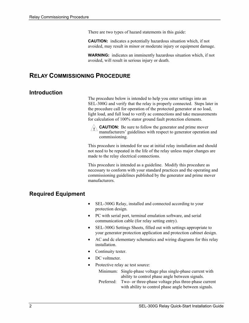
Introduction The procedure below is intended to help you enter settings into an SEL-300G and verify that the relay is properly connected. Steps later in the procedure call for operation of the protected generator at no load, light load, and full load to verify ac connections and take measurements for calculation of 100% stator ground fault protection elements.
CAUTION: Be sure to follow the generator and prime mover manufacturers’ guidelines with respect to generator operation and commissioning.
!
This procedure is intended for use at initial relay installation and should not need to be repeated in the life of the relay unless major changes are made to the relay electrical connections.
This procedure is intended as a guideline. Modify this procedure as necessary to conform with your standard practices and the operating and commissioning guidelines published by the generator and prime mover manufacturers.
Required Equipment • SEL-300G Relay, installed and connected according to your
protection design. • PC with serial port, terminal emulation software, and serial
communication cable (for relay setting entry). • SEL-300G Settings Sheets, filled out with settings appropriate to
your generator protection application and protection cabinet design. • AC and dc elementary schematics and wiring diagrams for this relay
installation. • Continuity tester. • DC voltmeter. • Protective relay ac test source:
Minimum: Single-phase voltage plus single-phase current with ability to control phase angle between signals.
Preferred: Two- or three-phase voltage plus three-phase current with ability to control phase angle between signals.
2 SEL-300G Relay Quick-Start Installation Guide

Relay Commissioning Procedure
Commissioning Procedure
DWG: M300G211
Correct VoltageConnections
STEP 17Connect Relay for
Tripping Duty
STEP 18Operate Generator
at No Load
STEP 19Operate Generator
at 10% Load
Are Voltage Signals Correct?
Record No LoadThird-Harmonic
Voltages
Are Current Signals Correct?
Correct CurrentConnections
STEP 8Connect PC to
Relay
STEP 14Verify Contact
Output Operation
STEP 15Perform Protection
Element Tests
STEP 16Confirm Tripping
Settings
STEP 1Remove DC
Power
Start
STEP 2AC & DC
Continuity Checks
STEP 4Power Supply DCPolarity Checks
(See Fig 2)
STEP 5Contact Output DC
Polarity Checks
STEP 6Remove AC
Signals
STEP 7Energize Relay
Shut DownGenerator
STEP 20Operate Generator
at Full Load. RecordThird-Harmonic
Voltages
STEP 21Shut DownGenerator
STEP 22Calculate and
Enter 64GElement Settings
STEP 23Clear RelayData Buffers
Are 64G ElementSettings Final?
End
Yes
No
Yes
No
Yes
No
STEP 3Modify Circuit
Board Jumpers
STEP 9Run Emulation
Software
STEP 10ConfigureEmulationSoftware
STEP 13Verify Contact
Input Operation
STEP 12Verify AC Wiring(See Fig 3 & 4)
STEP 11Enter Relay
Settings
Figure 1: Relay Commissioning Flowchart (refer to text for detailed instructions)
SEL-300G Relay Quick-Start Installation Guide 3

Relay Commissioning Procedure
Step 1. Ensure that dc power is removed from the SEL-300G dc circuits by opening the appropriate dc breaker or removing dc fuses.
Step 2. Verify the accuracy and correctness of the ac and dc connections by performing point-to-point continuity checks on the circuits associated with the SEL-300G Relay.
Step 3. Make any necessary modifications to the relay output contact jumper positions, password or breaker command jumper positions. Refer to Circuit Board Jumpers for additional details and instructions on how to access and modify these jumpers.
Step 4. Using a voltmeter, check the polarity of dc voltage on the energized side of the dc circuit breaker or fuse block that isolates the SEL-300G dc power supply inputs, terminals Z25 and Z26. Refer to Figure 2. Verify continuity between the positive, low-side terminal of the breaker or fuse block and terminal Z25 marked “+”. Verify continuity between the negative, low-side terminal of the breaker or fuse block and terminal Z26 marked “–”. This step is important because the SEL-300G 24/48 Vdc power supply is polarity sensitive.
! CAUTION: Do not apply reverse polarity dc voltage or ac voltage to terminals Z25 and Z26 of SEL-300G Relays rated for 24/48 Vdc applications. Relay failure and permanent power supply damage will result from application of reverse polarity dc voltage to relays rated for 24/48 Vdc applications.
DWG: M300G103
SEL-300G Relay(Partial)
ohms
com
0.0 ohms
To BatteryBank
+ DC
com
+Vdc
DC fuse block(or DC circuitbreaker) withfuses removed.
1
2 3
1 Verify correctDC polarity atfuse block input.
2 Verify continuityfrom fuse block+dc to relay +dcpower supplyterminal Z25.
3 Verify continuityfrom fuse block-dc to relay -dcpower supplyterminal Z26.
Z26Z25
Figure 2: DC Supply Polarity, Continuity Checks
4 SEL-300G Relay Quick-Start Installation Guide

Relay Commissioning Procedure
Step 5. Select models of the SEL-300G_1 or SEL-300G_Y are equipped with polarity sensitive, high current interrupting output contacts. When the relay is so equipped, it will have + polarity marks above even-numbered terminals in the B-series, such as B02, B04, etc. If your relay output contacts include polarity marks, review your dc wiring diagrams to ensure that even-numbered terminals are applied at a higher potential than odd-numbered terminals in their dc circuits.
Note If an output contact is polarity marked, do not use it to switch ac control signals. If an output contact is not polarity marked, it is not polarity sensitive and can be connected with either terminal at the higher potential. Step 6. In preparation to energize and set the relay, remove ac signals
from the relay and isolate its tripping contacts.
Step 7. Energize the relay by closing the dc breaker or installing the dc fuses. Within a moment of energizing the relay, the green enable LED (EN) on the front panel should illuminate, and the relay self-test ALARM contact (A15, A16) should open (type “b” contact).
Step 8. Connect the PC to the relay using the appropriate serial cable. Refer to Table 1 for typical cable numbers. These cables are available directly from SEL or you can build your own cable using the cable pinout shown in the SEL-5801 Cable Selector Software. This software is available from SEL, or can be downloaded free of charge from the SEL World Wide Web site at http://www.selinc.com.
Serial Port 1 on all the SEL-300G models is an EIA-485 port (4-wire). The Serial Port 1 plug-in connector accepts wire size AWG 24 to 12. Strip the wires 0.31 inches (8 mm) and install with a small slotted-tip screwdriver. Serial Port 1 connector has extra positions for IRIG-B time-code signal input.
All EIA-232 ports accept 9-pin D-subminiature male connectors. Port 2 on all the SEL-300G models also accepts demodulated IRIG-B time-code signal input.
Note Listing of devices not manu-factured by SEL in Table 1 isfor the convenience of ourcustomers. SEL does not spe-cifically endorse or recommendsuch products, nor does SELguarantee proper operation ofthose products, or the correct-ness of connections, overwhich SEL has no control.
Refer to Table 1 for a list of cables available from SEL for various communication applications.
For example, to connect any EIA-232 port to the 9-pin male connector on a laptop computer, order cable number C234A and specify the length needed (standard length is eight feet). For connecting devices at distances over 100 feet, SEL offers fiber-optic transceivers. The SEL-2800 family of transceivers provides fiber-optic links between devices for electrical isolation and long distance signal transmission. Contact SEL for further information on these products.
SEL-300G Relay Quick-Start Installation Guide 5

Relay Commissioning Procedure
Table 1: Communication Cables to Connect the SEL-300G Relay to Other Devices
SEL-300G EIA-232 Serial Ports
Connect to Device (gender refers to the device) SEL Cable #
all EIA-232 ports PC, 25-Pin Male (DTE2) C227A all EIA-232 ports Laptop PC, 9-Pin Male (DTE2) C234A all EIA-232 ports SEL Communications Processors
without IRIG-B C272A
2 SEL Communications Processors with IRIG-B
C273A
all EIA-232 ports SEL-PRTU C231 2 SEL-IDM, Ports 2 through 11 C254 + C257 21 31
StarComm Modem, 5 Vdc Powered C220
all EIA-232 ports Standard Modem, 25-Pin Female (DCE3)
C222
all EIA-232 ports RFL-9660 C245A All EIA-232 ports (with SEL-2800 transceiver)
SEL-2600 Series RTD Module C805Z010VVX0003 (3 meters)4
All EIA-232 ports (with SEL-2812MR transceiver)
SEL-2664 Field Ground Module SEL C805 Multimode 200 μm core diameter fiber-optic cable with
ST connectors, or SEL C807 Multimode 62.5 μm core diameter fiber-optic cable with
ST connectors 1A corresponding main board jumper must be installed to power the StarComm Modem with +5 Vdc (0.5 A limit) from the SEL-300G. See Figure 20 and Table 11.
2Data Terminal Equipment 3Data Communication Equipment 4Refer to Model Option Table for additional cable choices.
6 SEL-300G Relay Quick-Start Installation Guide
Relay Commissioning Procedure
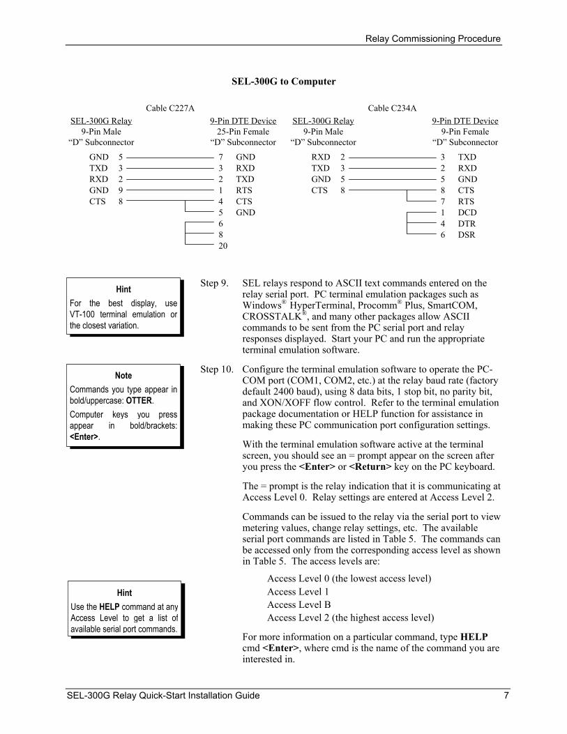
SEL-300G to Computer
RXD 2TXD 3GND 5CTS 8
3 TXD2 RXD5 GND8 CTS7 RTS1 DCD4 DTR6 DSR
SEL-300G Relay9-Pin Male
“D” Subconnector
Cable C234A9-Pin DTE Device
9-Pin Female“D” Subconnector
GND 5TXD 3RXD 2GND 9CTS 8
7 GND3 RXD2 TXD1 RTS4 CTS5 GND6820
SEL-300G Relay9-Pin Male
“D” Subconnector
Cable C227A9-Pin DTE Device
25-Pin Female“D” Subconnector
Step 9. SEL relays respond to ASCII text commands entered on the relay serial port. PC terminal emulation packages such as Windows
Hint For the best display, useVT-100 terminal emulation or the closest variation.
® HyperTerminal, Procomm® Plus, SmartCOM, CROSSTALK®, and many other packages allow ASCII commands to be sent from the PC serial port and relay responses displayed. Start your PC and run the appropriate terminal emulation software.
Step 10. Configure the terminal emulation software to operate the PC-COM port (COM1, COM2, etc.) at the relay baud rate (factory default 2400 baud), using 8 data bits, 1 stop bit, no parity bit, and XON/XOFF flow control. Refer to the terminal emulation package documentation or HELP function for assistance in making these PC communication port configuration settings.
Note Commands you type appear inbold/uppercase: OTTER. Computer keys you pressappear in bold/brackets: <Enter>.
With the terminal emulation software active at the terminal screen, you should see an = prompt appear on the screen after you press the <Enter> or <Return> key on the PC keyboard.
The = prompt is the relay indication that it is communicating at Access Level 0. Relay settings are entered at Access Level 2.
Commands can be issued to the relay via the serial port to view metering values, change relay settings, etc. The available serial port commands are listed in Table 5. The commands can be accessed only from the corresponding access level as shown in Table 5. The access levels are:
Access Level 0 (the lowest access level) Access Level 1 Hint Access Level B Use the HELP command at any
Access Level to get a list of available serial port commands.
Access Level 2 (the highest access level)
For more information on a particular command, type HELP cmd <Enter>, where cmd is the name of the command you are interested in.
SEL-300G Relay Quick-Start Installation Guide 7

Relay Commissioning Procedure
Passwords are required to move up in access levels if the main board Password jumper is not in place (Password jumper = OFF). Passwords are not required if the main board Password jumper is in place (Password jumper = ON). Refer to Table 9 and Table 10 for Password jumper information.
WARNING: This device is shipped with default passwords. Default passwords should be changed to private passwords at installation. Failure to change each default password to a private password may allow unauthorized access. SEL shall not be responsible for any damage resulting from unauthorized access.
!
The factory default passwords for Access Levels 1, B, and 2 are:
Access Level Factory Default Password 1 OTTER B EDITH 2 TAIL
At the Access Level 0 prompt, enter the ACC command:
=ACC <Enter>
If the Password jumper is not in place, the relay asks for the Access Level 1 password to be entered:
Password: ? @@@@@@
The relay is shipped with the default Access Level 1 password shown above. Enter the default password and press <Enter>.
The “=>” prompt indicates the relay is now in Access Level 1.
If the entered password is incorrect, the relay asks for the password again (Password: ?). The relay will ask up to three times. If the requested password is incorrectly entered three times, the relay closes the ALARM contact for one second and remains at Access Level 0 (“=” prompt).
If the Password jumper is in place, the relay does not ask for a password; it goes directly to Access Level 1.
The above two examples demonstrate how to go from Access Level 0 to Access Level 1. The procedure to go from Access Level 1 to Access Level B, Access Level 1 to Access Level 2, or Access Level B to Access Level 2 is much the same, with command BAC or 2AC entered at the access level screen prompt. The relay closes the ALARM contact for one second after a successful Level B or Level 2 access. If access is denied, the ALARM contact closes for one second.
Enter the 2AC command at the Access Level 1 prompt:
=>2AC <Enter>
8 SEL-300G Relay Quick-Start Installation Guide

Relay Commissioning Procedure
If the password jumper is not in place, enter the factory default Access Level 2 password.
Step 11. Using the SET 1, SET 2, SET G, SET R, and SET P commands, enter relay settings according to the Settings Sheets for your application.
When you issue the SET command, the relay presents a list of settings, one at a time. Enter a new setting, or press <Enter> to accept the existing setting. Editing keystrokes are shown in Table 2.
Table 2: SET Command Editing Keystrokes
Press Key(s) Results
<Enter> Retains setting and moves to the next setting.
^ <Enter> Returns to previous setting.
< <Enter> Returns to previous setting category.
> <Enter> Moves to next setting category.
END <Enter> Exits editing session, then prompts you to save the settings.
<Ctrl> X Aborts editing session without saving changes.
The relay checks each entry to ensure that it is within the setting range. If it is not, an “Out of Range” message is generated, and the relay prompts for the setting again.
When all the settings are entered, the relay displays the new settings and prompts for approval to enable them. Answer Y<Enter> to enable the new settings. If changes are made to Global, SER, or Port settings, the relay is disabled while it saves the new settings. If changes are made to the Group settings for the active setting group, the relay is disabled while it saves the new settings. The ALARM contact closes momentarily and the EN LED extinguishes while the relay is disabled. The relay is disabled for as long as 15 seconds.
If changes are made to the Group settings for the inactive setting group, the relay is not disabled while it saves the new settings. The ALARM contact closes momentarily, but the EN LED remains on while the new settings are saved.
If pickup settings for 100% stator ground element 64G2 have not been calculated, leave Relay Word bit 64G2T out of tripping control equations. Set the Breaker Monitor function SELOGIC® control equation enable BKMON = 0 in the Global relay settings. This disables the Breaker Monitor function while the relay is being tested.
Step 12. Verify relay ac connections. Connect the protective relay ac test signal source to the SEL-300G through the ac protection
SEL-300G Relay Quick-Start Installation Guide 9

Relay Commissioning Procedure
cabinet wiring. (You may connect directly to the relay, however this does not verify the accuracy of the wiring in the protection cabinet.) Apply rated ac voltage (67 V1n, 120 V11) and current (1 A or 5 A) to the relay phase voltage and current inputs. Set the test source phase angles to supply no phase difference between phase voltage and phase current.
If a three-phase test source is used, set the source phase angles as shown in Figure 3:
When setting PHROT = ABC, set angle Va = angle Ia = 0° set angle Vb = angle Ib = -120° set angle Vc = angle Ic = 120°
When setting PHROT = ACB, set angle Va = angle Ia = 0° set angle Vb = angle Ib = 120° set angle Vc = angle Ic = -120°
+120°
-120°
VC
VB
VA
PHROT = ABC
+120°
-120°
PHROT = ACB
DWG: M300G104
VB
VC
VA
Figure 3: Three-Phase AC Connection Test Voltage Signals
If open-delta potentials are used, set the test source phase angles as shown in Figure 4:
When setting PHROT = ABC, set angle Ia =0° set angle Ib = -120° set angle Ic = 120° set angle Vab = +30° set angle Vcb = +90°
When setting PHROT = ACB, set angle Ia = 0° set angle Ib = 120° set angle Ic = -120° set angle Vab = -30° set angle Vcb = -90°
10 SEL-300G Relay Quick-Start Installation Guide

Relay Commissioning Procedure
DWG: M300G200
60° VAB
VCB
PHROT = ABC
60°
VAB
VCB
PHROT = ACB
Figure 4: Open-Delta AC Potential Connection Test Voltage Signals
If a single-phase source is used, set the source phase angles to zero and apply the voltage and current to phases A, B, and C in turn.
Use the front-panel or serial port METER function to verify that the relay is measuring voltage and current magnitudes and phase angles correctly, taking into account the relay PTR and CTR settings and the fact that the quantities are displayed in primary units.
Apply rated ac voltage (67V) to the relay VS and VN inputs if provided and used. Apply rated ac current (1 A or 5 A) to the relay IN input if used. Use the front-panel or serial port METER function to verify that the relay is measuring voltage and current magnitudes and phase angles correctly, taking into account the relay PTRN, PTRS, and CTRN settings and the fact that the quantities are displayed in primary units.
Step 13. Verify optoisolated input connections. Use the front-panel OTHER pushbutton and the TAR function to cause the relay to display Relay Word Row 31 on the relay front-panel LEDs. Apply rated dc voltage to the individual relay optoisolated input circuits. As you apply dc voltage to each input, its label will appear in the LCD display and its LED will illuminate.
Execution of the TAR command via the front-panel display remaps the bottom row of the front-panel target LEDs (see Figure 7, pushbutton OTHER).
For instance, the TAR 31 command associates the front-panel 87 LED with input IN101. When rated dc voltage is applied to IN101, the 87 LED illuminates. Verify inputs IN201 through IN208 of SEL-300G_1 and SEL-300G_Y Relays using TAR 40. When input verification is complete, press the TARGET RESET or EXIT pushbutton to reset the front-panel target LEDs.
SEL-300G Relay Quick-Start Installation Guide 11
Relay Commissioning Procedure
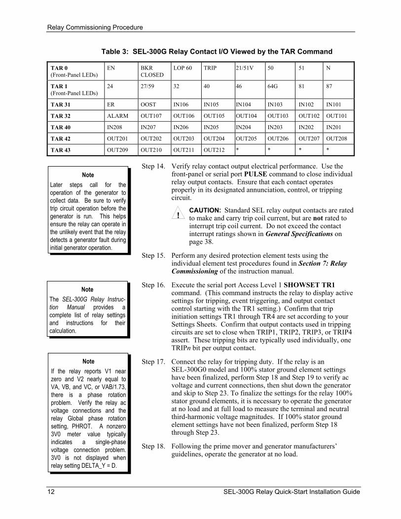
Table 3: SEL-300G Relay Contact I/O Viewed by the TAR Command
EN BKR CLOSED
LOP 60 TRIP 21/51V 50 51 N TAR 0 (Front-Panel LEDs)
24 27/59 32 40 46 64G 81 87 TAR 1 (Front-Panel LEDs)
ER OOST IN106 IN105 IN104 IN103 IN102 IN101 TAR 31
ALARM OUT107 OUT106 OUT105 OUT104 OUT103 OUT102 OUT101 TAR 32
IN208 IN207 IN206 IN205 IN204 IN203 IN202 IN201 TAR 40
OUT201 OUT202 OUT203 OUT204 OUT205 OUT206 OUT207 OUT208 TAR 42
OUT209 OUT210 OUT211 OUT212 * * * * TAR 43
Step 14. Verify relay contact output electrical performance. Use the front-panel or serial port PULSE command to close individual relay output contacts. Ensure that each contact operates properly in its designated annunciation, control, or tripping circuit.
Note Later steps call for theoperation of the generator tocollect data. Be sure to verifytrip circuit operation before thegenerator is run. This helpsensure the relay can operate inthe unlikely event that the relaydetects a generator fault duringinitial generator operation.
!CAUTION: Standard SEL relay output contacts are rated to make and carry trip coil current, but are not rated to interrupt trip coil current. Do not exceed the contact interrupt ratings shown in General Specifications on page
38.
Step 15. Perform any desired protection element tests using the individual element test procedures found in Section 7: Relay Commissioning of the instruction manual.
Step 16. Execute the serial port Access Level 1 SHOWSET TR1 command. (This command instructs the relay to display active settings for tripping, event triggering, and output contact control starting with the TR1 setting.) Confirm that trip initiation settings TR1 through TR4 are set according to your Settings Sheets. Confirm that output contacts used in tripping circuits are set to close when TRIP1, TRIP2, TRIP3, or TRIP4 assert. These tripping bits are typically used individually, one TRIPn bit per output contact.
Note The SEL-300G Relay Instruc-tion Manual provides acomplete list of relay settingsand instructions for theircalculation.
Note Step 17. Connect the relay for tripping duty. If the relay is an SEL-300G0 model and 100% stator ground element settings have been finalized, perform
If the relay reports V1 nearzero and V2 nearly equal toVA, VB, and VC, or VAB/1.73,there is a phase rotation problem. Verify the relay acvoltage connections and therelay Global phase rotationsetting, PHROT. A nonzero3V0 meter value typicallyindicates a single-phase voltage connection problem.3V0 is not displayed whenrelay setting DELTA_Y = D.
Step 18 and Step 19 to verify ac voltage and current connections, then shut down the generator and skip to Step 23. To finalize the settings for the relay 100% stator ground elements, it is necessary to operate the generator at no load and at full load to measure the terminal and neutral third-harmonic voltage magnitudes. If 100% stator ground element settings have not been finalized, perform Step 18 through Step 23.
Step 18. Following the prime mover and generator manufacturers’ guidelines, operate the generator at no load.
12 SEL-300G Relay Quick-Start Installation Guide

Relay Commissioning Procedure
!CAUTION: Be sure to follow the generator and prime mover manufacturers’ guidelines with respect to generator operation and commissioning.
Use the relay front-panel or serial port METER command to display the ac quantities measured by the relay. Note the voltage magnitudes and phase angles. Voltage magnitudes should be nearly equal. Voltage phase angles should be balanced and have proper phase rotation. The positive-sequence voltage magnitude, V1, should be nearly equal to VA, VB, and VC, or VAB/1.73. The negative-sequence voltage magnitude (V2) and zero-sequence voltage magnitude (3V0, if shown) should both be nearly zero.
After correcting any problems indicated by the phase and sequence voltage measurements, record the VN3 and VP3 third-harmonic voltage magnitudes.
Step 19. Increase generator loading to approximately 10% of full load. Use the relay front-panel or serial port METER command to display the ac quantities measured by the relay. Note the phase current magnitudes and phase angles. Phase current magnitudes should be nearly equal. Phase current phase angles should be balanced, have proper phase rotation, and appropriate phase relationship to their phase voltages. The positive-sequence current magnitude, I1, should be nearly equal to IA, IB, and IC. The negative-sequence current magnitude, I2, and residual current magnitude should both be nearly zero.
Note If the relay reports I1 near zero and I2 nearly equal to IA, IB, and IC, there is a phase rotation problem. Verify the relay ac current connections and the relay Global phase rotation setting, PHROT. A nonzero 3I0 meter value indicates a phase current polarity connection problem.
If the relay is an SEL-300G1 or SEL-300G3 model, use the front-panel or serial port METER DIF command to check differential protection quantities. Differential operate current quantities IOP1, IOP2, and IOP3 should be near zero. Note
If the SEL-300G1/300G3 Relay METER DIF function reports nonzero differential operate currents, there is likely a differential current transformer connection problem or a problem with the TRCON or CTCON settings. Use the Differential Element Commissioning Worksheet to determine the nature of the connection problem.
Step 20. Operate the generator at full load. Use the front-panel or serial port METER command to display the ac quantities measured by the relay. Note the ac voltage and current magnitude and phase angle measurements, using the same criteria as in Step 19. Having made any necessary corrections during early steps, the measurements should now be correct. Record the terminal and neutral third-harmonic voltage magnitudes VP3 and VN3.
Step 21. Shut down the generator.
Step 22. Calculate settings for the 64G2 element using the measurements taken above and the guidelines shown in Section 2: Relay Element Settings of the SEL-300G Relay Instruction Manual. Using the serial port SET command, enter the newly calculated 64G element settings and add 64G2T to tripping SELOGIC control equations. If desired, perform 64G protection element tests to verify the element performance with the new settings.
SEL-300G Relay Quick-Start Installation Guide 13

Serial Port Command Summary
Step 23. To prepare the relay for operation, it is usually helpful to clear several of the relay data buffers. This prevents data generated during installation testing from being confused with operational data collected later. Execute the relay commands in Table 4 to clear specific data.
Table 4: Serial Port Commands That Clear Relay Data Buffers
Note The PRO R and SER C commands should only be used at initial installation. Do not reset the generator operating profiles or SER buffer following routine maintenance unless you are very familiar with the use of the data contained in these buffers.
Command Task Performed:
Resets Demand Meter Data MET RD
Resets Peak Demand Meter Data MET RP
Resets Energy Meter Data MET RE
Resets Max/Min Data MET RM
Clears Event Report and History Command Buffers HIS C
Resets Selected Generator Operating Statistic Buffers PRO R
Clears Sequential Events Record Buffer SER C
Set the Breaker Monitor function SELOGIC control equation enable BKMON back to the setting specified by your Settings Sheets. If desired, use the SHO 1, SHO 2, SHO G, and SHO R commands to record the relay settings. The relay is now ready for operation.
SERIAL PORT COMMAND SUMMARY
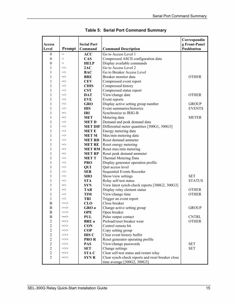
Table 5 alphabetically lists the serial port commands within a given access level. Much of the information available from the serial port commands is also available via the front-panel pushbuttons. The correspondence between the serial port commands and the front-panel pushbuttons is also given in Table 5. See Front-Panel Pushbutton Operation for more information on the front-panel pushbuttons.
The serial port commands at the different access levels offer varying levels of control:
• The Access Level 1 commands allow the user to look at information only (settings, metering, etc.), not change it.
• The Access Level B commands allow the user to operate output contacts or change the active setting group.
• The Access Level 2 commands allow the user to change relay settings.
If you are communicating at a higher access level, you may also use serial port commands from lower access levels. The commands are shown in upper-case letters, but they can also be entered with lower-case letters.
14 SEL-300G Relay Quick-Start Installation Guide
Serial Port Command Summary
Table 5: Serial Port Command Summary
Corresponding Front-Panel Pushbutton
Access Level
Serial Port Command Prompt Command Description
ACC 0 = Go to Access Level 1 CAS 0 = Compressed ASCII configuration data HELP 0 = Display available commands 2AC 1 => Go to Access Level 2 BAC 1 => Go to Breaker Access Level BRE 1 => Breaker monitor data OTHER CEV 1 => Compressed event report CHIS 1 => Compressed history CST 1 => Compressed status report DAT 1 => View/change date OTHER EVE 1 => Event reports GRO 1 => Display active setting group number GROUP HIS 1 => Event summaries/histories EVENTS IRI 1 => Synchronize to IRIG-B MET 1 => Metering data METER MET D 1 => Demand and peak demand data MET DIF1 => Differential meter quantities [300G1, 300G3] MET E 1 => Energy metering data MET M 1 => Max/min metering data MET RD 1 => Reset demand ammeter MET RE 1 => Reset energy metering MET RM1 => Reset max/min metering MET RP 1 => Reset peak demand ammeter MET T 1 => Thermal Metering Data PRO 1 => Display generator operation profile QUI 1 => Quit access level SER 1 => Sequential Events Recorder SHO 1 => Show/view settings SET STA 1 => Relay self-test status STATUS SYN 1 => View latest synch-check reports [300G2, 300G3] TAR 1 => Display relay element status OTHER TIM 1 => View/change time OTHER TRI 1 => Trigger an event report CLO B ==> Close breaker GRO n B ==> Change active setting group GROUP OPE B ==> Open breaker PUL B ==> Pulse output contact CNTRL BRE n 2 =>> Preload/reset breaker wear OTHER CON 2 =>> Control remote bit COP 2 =>> Copy setting group HIS C 2 =>> Clear event history buffer PRO R 2 =>> Reset generator operating profile PAS 2 =>> View/change passwords SET SET 2 =>> Change settings SET STA C 2 =>> Clear self-test status and restart relay SYN R 2 =>> Clear synch-check reports and reset breaker close
time average [300G2, 300G3]
SEL-300G Relay Quick-Start Installation Guide 15

Front-Panel Pushbutton Operation
FRONT-PANEL PUSHBUTTON OPERATION
Overview Note in Figure 5 that most of the pushbuttons have dual functions (primary/secondary). A primary function is selected first (e.g., METER pushbutton).
After a primary function is selected, the pushbuttons then revert to operating on their secondary functions (CANCEL, SELECT, left/right arrows, up/down arrows, EXIT). For example, after the METER pushbutton is pressed, the up/down arrows are used to scroll through the front-panel metering screens. The primary functions are activated again when the present selected function (metering) is exited (press EXIT pushbutton) or the display goes back to the default display after no front-panel activity for a settable time period.
TARGETRESET
LAMPTEST
EVENTSMETER STATUS SET GROUPOTHER CNTRL
CANCEL SELECT EXIT
(Dual FunctionPrimary
Secondary) DWG: Q300G002a
Also hasSecondary Function
(see Figure 8)
Figure 5: SEL-300G Front-Panel Pushbuttons – Overview
Primary Functions Note in Figure 6 and Figure 7 that the front-panel pushbutton primary functions correspond to serial port commands – both retrieve the same information or perform the same function. To get more detail on the information provided by the front-panel pushbutton primary functions, refer to the corresponding serial port commands in Table 5 in Serial Port Command Summary.
The Local Control front-panel primary functions do not have a serial port command equivalent.
16 SEL-300G Relay Quick-Start Installation Guide

Front-Panel Pushbutton Operation
TARGETRESET
LAMPTEST
METER EVENTS STATUS
DWG: M300G137
View Instantaneous,Energy, Max./Min.,
and DemandMetering Values,
Reset Energy,Max./Min., Differential,
andDemand Metering
Values
ViewEvent
Summaries
ViewSelf-Test
Status
HIS STA
FunctionDescription
CorrespondingSerial PortCommands at:
Access Level 1*
* Front-panel pushbutton functions that correspond to Access Level 1 serial port commandsdo not require the entry of the Access Level 1 password through the front panel.
METMET DMET EMET M
MET RDMET REMET RM
MET RPMET DIFMET T
Figure 6: SEL-300G Front-Panel Pushbuttons – Primary Functions
Front-Panel Password Security Refer to the comments at the bottom of Figure 7 concerning Access Level B and Access Level 2 passwords.
To enter the Access Level B and Access Level 2 passwords from the front panel (if required), use the left/right arrow pushbuttons to underscore a password character position. Use the up/down arrow pushbuttons to then change the character. Press the SELECT pushbutton once the correct Access Level B or Access Level 2 password is ready to enter.
The factory default passwords for Access Level 1, B, and 2 are listed at the front of this guide under Step 10 of the Commissioning Procedure.
SEL-300G Relay Quick-Start Installation Guide 17

Front-Panel Pushbutton Operation
OTHER SET CNTRL GROUP
DWG: M300G138a
Display ActiveSetting Group
Number; ChangeActive Setting
Group
FunctionDescription
CorrespondingSerial PortCommands at:
Access Level 11
Access Level B 2
Access Level 2 3
View or Reset BreakerMonitor Data; View orChange Date or Time;View Asserted Relay
Word Bits
BREDATTIMTAR
BRE R
View or ChangeGroup, Global, or
Serial Port Settings;Change Passwords
SHO nSHO GSHO P
SET nSET GSET PPAS
Pulse OutputContacts 4
View or OperateLocal Control 5
PUL
GRO
GRO n
1 Front-panel pushbutton functions that correspond to Access Level 1 serial port commands do not requirethe entry of the Access Level 1 password through the front panel.
2 Front-panel pushbutton functions that correspond to Access Level B serial port commands do requirethe entry of the Access Level B or Access Level 2 passwords through the front panel if the main boardPassword jumper is not in place (see Tables 9 and 10).
3 Front-panel pushbutton functions that correspond to Access Level 2 serial port commands do require theentry of the Access Level 2 passwords through the front panel if the main board Password jumper is notin place (see Tables 9 and 10).
4 Output contacts are pulsed for only 1 second from the front panel.5 Local control is not available through the serial port and does not require the entry of a password.
Figure 7: SEL-300G Front-Panel Pushbuttons – Primary Functions (continued)
Secondary Functions After a primary function is selected (see Figure 6 and Figure 7), the pushbuttons then revert to operating on their secondary functions (see Figure 8).
Use the left/right arrows to underscore a desired function. Then press the SELECT pushbutton to select the function.
Use left/right arrows to underscore a desired setting digit. Then use the up/down arrows to change the digit. After the setting changes are complete, press the SELECT pushbutton to select/enable the setting.
Press the CANCEL pushbutton to abort a setting change procedure and return to the previous display. Press the EXIT pushbutton to return to the default display and have the primary pushbutton functions activated again (see Figure 6 and Figure 7).
18 SEL-300G Relay Quick-Start Installation Guide

Front-Panel Pushbutton Operation
CANCEL
DWG: M300G139a
Cancel SettingEdit or
Escape to UpperSetting Level
TARGETRESET
LAMPTEST
Provides HelpScreen
Information WhenViewing or Changing
Settings withPushbutton SET
FunctionDescription
Scroll Left onDisplay toUnderlineDesired
Function orSetting Digit
Scroll Right onDisplay toUnderlineDesired
Function orSetting Digit
Scroll Up onDisplay; Increment
Setting Value
Scroll Down onDisplay; Decrement
Setting Value
FunctionDescription
Select Displayed Optionor Setting
SELECT
Exit Entirely andReturn to
Default Display
EXIT
QUI
FunctionDescription
Corresponding SerialPort Commands at:
Access Level 1*
*Front-panel pushbutton functions that correspond to Access Level 1 serial port commands do not requirethe entry of the Access Level 1 password through the front panel.
The front-panel display gives indication of the arrow button to use(Displays symbols: ← → ↑↓)
Figure 8: SEL-300G Front-Panel Pushbuttons – Secondary Functions
SEL-300G Relay Quick-Start Installation Guide 19

Relay Mounting
RELAY MOUNTING
Figure 9: SEL-300G Dimensions and Panel-Mount Cut-Out
20 SEL-300G Relay Quick-Start Installation Guide

Relay Mounting
Figure 10: SEL-300G Relay Front-Panel Drawings for Rack-Mount Relays (2U and 3U), Screw-Terminal Block and Connectorized® Versions
SEL-300G Relay Quick-Start Installation Guide 21

Relay Mounting
Figure 11: SEL-300G Relay Front-Panel Drawings for Panel-Mount Relays (2U and 3U), Screw-Terminal Block and Connectorized Versions
22 SEL-300G Relay Quick-Start Installation Guide

Relay Mounting
Figure 12: SEL-300G0 Relay Rear-Panel Drawings for Rack- and Panel-Mount Relays (2U and 3U), Screw-Terminal Block Version
SEL-300G Relay Quick-Start Installation Guide 23

Relay Mounting
Figure 13: SEL-300G1 Relay Rear-Panel Drawings for Rack- and Panel-Mount Relays (2U and 3U), Screw-Terminal Block Version
24 SEL-300G Relay Quick-Start Installation Guide

Relay Mounting
Figure 14: SEL-300G2 Relay Rear-Panel Drawings for Rack- and Panel-Mount Relays (2U and 3U), Screw-Terminal Block Version
SEL-300G Relay Quick-Start Installation Guide 25

Relay Mounting
Figure 15: SEL-300G3 Relay Rear-Panel Drawings for Rack- and Panel-Mount Relays (2U and 3U), Screw-Terminal Block Version
26 SEL-300G Relay Quick-Start Installation Guide

Relay Mounting
Figure 16: SEL-300G0 Relay Rear-Panel Drawings for Rack- and Panel-Mount Relays (2U and 3U), Connectorized Version
SEL-300G Relay Quick-Start Installation Guide 27

Relay Mounting
Figure 17: SEL-300G1 Relay Rear-Panel Drawings for Rack- and Panel-Mount Relays (2U and 3U), Connectorized Version
28 SEL-300G Relay Quick-Start Installation Guide

Relay Mounting
Figure 18: SEL-300G2 Relay Rear-Panel Drawings for Rack- and Panel-Mount Relays (2U and 3U), Connectorized Version
SEL-300G Relay Quick-Start Installation Guide 29

Relay Mounting
Figure 19: SEL-300G3 Rear-Panel Drawings for Rack- and Panel-Mount Relays (2U and 3U), Connectorized Version
30 SEL-300G Relay Quick-Start Installation Guide

Circuit Board Jumpers
CIRCUIT BOARD JUMPERS
Accessing the Relay Main Board (All Models) and Extra I/O Board (Models 0300G_1 and 0300G_Y)
To change circuit board jumpers or replace the clock battery on the relay main board (or change output contact jumpers on the extra I/O board), refer to Figure 20, Figure 21, or Figure 22 and take the following steps:
Step 1. Deenergize the relay. On Connectorized versions this can be accomplished easily by removing the connector at rear-panel terminals Z25 and Z26.
Step 2. Remove any cables connected to serial ports on the front and rear panels.
Step 3. Loosen the six front-panel screws (they remain attached to the front panel), and remove the relay front panel.
!
CAUTION: The relay contains devices sensitive to electrostatic discharge (ESD). When working on the relay with front or top cover removed, work surfaces and personnel must be properly grounded or equipment damage may result.
Step 4. Identify which drawout board needs to be changed. All SEL-300G models have a main board in the top guides, and Models 0300G_1 and 0300G_Y have an extra I/O board below the main board. Each board corresponds to a row of rear-panel screw-terminal blocks.
Step 5. On Connectorized versions, remove the rear-panel connectors that correspond to the circuit board you wish to remove by loosening the screws on either end of each connector. Removal of the extra I/O board also requires removal of the main board (because the LCD on the main board is in the way).
Step 6. On screw-terminal block models, disconnect the ribbon cables from the board(s). Grasp the drawout assembly of the board, and pull the assembly from the relay chassis. In Models 0300G_1 and 0300G_Y, the extra I/O board directly below the main board requires removal of the main board first (because the LCD on the main board is in the way).
Step 7. Locate the jumper(s) or battery to be changed (refer to Figure 20, Figure 21, and Figure 22). Change the jumper position(s). Note that the output contact jumpers are soldered in place.
Step 8. Slide the drawout assemblies into the relay chassis (main board last). Reconnect the ribbon cables. Replace the relay front panel and reenergize the relay. On Connectorized versions, replace the power connector at rear-panel terminals Z25 and Z26.
SEL-300G Relay Quick-Start Installation Guide 31

Circuit Board Jumpers
ALARM
OUT106
OUT105
OUT104
OUT107
OUT103
OUT102
OUT101
OPT
OIS
OLA
TED
IN
PUTS
OU
TPU
T C
ON
TAC
TS
A
BJM
P29
DWG: M300G096
A
BJM
P28
A
BJM
P27
A
BJM
P26
A
BJM
P25
A
BJM
P24
A
BJM
P22
A
BJM
P21
JMP23
SE
RIA
LPO
RT
1(E
IA-4
85)
SE
RIA
LPO
RT
2(E
IA-2
32)
SE
RIA
LPO
RT
3(E
IA-2
32)
JMP1J1
JMP2
JMP6
AB
CD
µCU46
SE
RIA
LPO
RT
F(E
IA-2
32)
R13
1LE
Ds
PUSH
BUTT
ON
S
POW
ER
-I/O
CO
NN
ECTO
RA
NA
LOG
CO
NN
ECTO
R
LCD
CO
NTR
AST
ADJU
ST
J10
B1 C
LOC
KB
ATT
ER
YJ8
/J9
J7
Figure 20: Jumper, Connector, and Major Component Locations on the SEL-300G Main Board (All Models)
32 SEL-300G Relay Quick-Start Installation Guide

Circuit Board Jumpers
AB
AA
AA
AB
AB
OUT212
OUT211
OUT210
OUT209
OUT207
OUT206
OUT205
JMP17
JMP19
JMP18BB
BB
A
OUT208
B
AB
OUT204
AB
OUT203
AB
OUT202
OP
TOIS
OLA
TED
INP
UTS
OU
TPU
T C
ON
TAC
TS
AB
PO
WE
R -
I/O C
ON
NE
CTO
R
JMP20
JMP21
JMP22
JMP23
JMP24
JMP25
JMP26
JMP27
JMP28
OUT201
DWG: M300G095
Figure 21: Jumper, Connector, and Major Component Locations on the SEL-300G Extra I/O Board(Models 0300G_1, Screw-Terminal Block Version)
SEL-300G Relay Quick-Start Installation Guide 33

Circuit Board Jumpers
AB
AA
A
OUT212
OUT211
OUT210
OUT209
OUT207
OUT206
OUT205
JMP17
JMP19
JMP18BB
BOUT208
OUT204
OUT203
OUT202
OP
TOIS
OLA
TED
INP
UTS
OU
TPU
T C
ON
TAC
TS
PO
WER
- I/O
CO
NN
ECTO
R
JMP20
OUT201
DWG: M300G257
Figure 22: Jumper, Connector, and Major Component Locations on the SEL-300G Extra I/O Board (Model 0300G_Y, Plug-In Connector Version)
34 SEL-300G Relay Quick-Start Installation Guide

Circuit Board Jumpers
Output Contact Jumpers Table 6 shows the correspondence between output contact jumpers and the output contacts they control. The referenced figures show the exact location and correspondence. With a jumper in the A position, the corresponding output contact is an “a” type output contact. An “a” type output contact is open when the output contact coil is deenergized and closed when the output contact coil is energized. With a jumper in the B position, the corresponding output contact is a “b” type output contact. A “b” type output contact is closed when the output contact coil is deenergized and open when the output contact coil is energized. These jumpers are soldered in place.
Table 6In the figures referenced in , note that the ALARM output contacts are “b” type output contacts and the other output contacts are all “a” type output contacts. This is how these jumpers are configured in a standard relay shipment.
Table 6: Output Contact Jumpers and Corresponding Output Contacts
SEL-300G Relay Model Number
Output ContactJumpers
Corresponding Output Contacts
Reference Figures
All Models JMP21–JMP29(but not JMP23)
ALARM–OUT101 Figure 20
0300G_1 JMP17–JMP28 OUT212–OUT201 Figure 21
0300G_Y JMP17–JMP20 OUT212–OUT209 Figure 22
“Extra Alarm” Output Contact Control Jumper All the SEL-300Gs have dedicated alarm output contacts (labeled ALARM—see Figure 12 through Figure 19). Often more than one alarm output contact is needed for such applications as local or remote annunciation, backup schemes, etc. An extra alarm output contact can be obtained for all the SEL-300G models without the addition of any external hardware.
The output contact next to the dedicated ALARM output contact can be converted to operate as an “extra alarm” output contact by moving a jumper on the main board (see Table 7).
Table 7: “Extra Alarm” Output Contacts and Corresponding Controlling Jumpers
“Extra Alarm” Output Contact
Controlling Jumper Reference Figures
OUT107 JMP23 Figure 20
The position of the jumper controls the operation of the output contact next to the dedicated ALARM output contact. With the jumper in one
SEL-300G Relay Quick-Start Installation Guide 35

Circuit Board Jumpers
position, the output contact operates regularly. With the jumper in the other position, the output contact is driven by the same signal that operates the dedicated ALARM output contact (see Table 8).
Table 8: Required Position of Jumper JMP23 for Desired Output Contact OUT107 Operation (All Models)
Position Output Contact OUT107 Operation
DWG: M300G146
(1)
(2)
(3)
JMP2
3
Regular output contact OUT107 (operated by Relay Word bit OUT107). Jumper JMP23 comes in this position in a standard relay shipment.
DWG: M300G146
(1)
(2)
(3)
JMP2
3
“Extra Alarm” output contact (operated by alarm logic/circuitry). Relay Word bit OUT107 does not have any effect on output contact OUT107 when jumper JMP23 is in this position.
If an output contact is operating as an “extra alarm” (driven by the same signal that operates the dedicated ALARM output contact), it will be in the opposite state of the dedicated ALARM output contact in a standard relay shipment. In a standard relay shipment, the dedicated ALARM output contact comes as a “b” type output contact and all the other output contacts (including the “extra alarm”) come as “a” type output contacts.
The output contact type for any output contact can be changed (see preceding subsection Output Contact Jumpers). Thus, the dedicated ALARM output contact and the “extra alarm” output contact can be configured as the same output contact type if desired (e.g., both can be configured as “b” type output contacts).
36 SEL-300G Relay Quick-Start Installation Guide

Password and Breaker Jumpers
Table 9: Password and Breaker Jumper Positions for Standard Relay Shipments
Password Jumper/Position
(for standard relay shipments)
Breaker Jumper/Position
(for standard relay shipments)
Reference Figures
JMP6-A = OFF JMP6-B = ON Figure 20
Table 10: Password and Breaker Jumper Operation
Jumper Type Jumper Position Function
1Password ON (in place)
disable password protection for serial ports and front panel
OFF (removed/not in place)
enable password protection1 for serial ports and front panel
Breaker ON (in place)
enable serial port commands OPEN, CLOSE, and PULSE2
OFF (removed/not in place)
disable serial port commands OPEN, CLOSE, and PULSE2
1View or set the passwords with the PASSWORD command. 2The OPEN, CLOSE, and PULSE commands are used primarily to assert output
contacts for circuit breaker control or testing purposes.
Note that jumper JMP6 in Figure 20 has C and D jumper positions, too. Jumpers should not be installed in the C and D jumper positions.
EIA-232 Serial Port Voltage Jumpers The jumpers listed in Table 11 connect or disconnect +5 Vdc to Pin 1 on the corresponding EIA-232 serial ports. The +5 Vdc is rated at 0.5 A maximum for each port.
In a standard relay shipment, the jumpers are “OFF” (removed/not in place) so that the +5 Vdc is not connected to Pin 1 on the corresponding EIA-232 serial ports. Put the jumpers “ON” (in place) so that the +5 Vdc is connected to Pin 1 on the corresponding EIA-232 serial ports.
Table 11: EIA-232 Serial Port Voltage Jumper Positions for Standard Relay Shipments
EIA-232 Serial Port 2 (rear panel)
EIA-232 Serial Port 3 (rear panel) Reference Figures
JMP2 = OFF JMP1 = OFF Figure 20
SEL-300G Relay Quick-Start Installation Guide 37

Specifications
SPECIFICATIONS General Terminal Connections: 1 s Rating: 50 A Tightening Torque Terminal Block: Minimum: 8 in-lb (0.9 Nm)
Maximum: 12 in-lb (1.4 Nm) Connectorized: Minimum: 4.4 in-lb (0.5 Nm)
Maximum: 8.8 in-lb (1.0 Nm) Terminals or stranded copper wire. Ring terminals are recommended. Minimum temperature rating of 105°C.
AC Current Inputs: 5 A Nominal 15 A continuous, linear to 100 A symmetrical. 500 A for 1 second. 1250 A for 1 cycle. Burden: 0.27 VA @ 5 A 2.51 VA @ 15 A 1 A Nominal 3 A continuous, linear to 20 A symmetrical 100 A for 1 second. 250 A for 1 cycle. Burden: 0.13 VA @ 1 A 1.31 VA @ 3 A
AC Voltage Inputs: 80–208 VL-L Nominal, for 4-wire wye voltage input. 80–140 VL-L Nominal, for 3-wire delta voltage input. 300 VL-N continuous limit for 3-phase, 4-wire wye-connection. 300 VL-L continuous limit for 3-phase, 3-wire delta-connection. 300 V continuous, VN–NN neutral voltage input. 300 V continuous, VS–NS synch voltage input. 365 Vac for 10 seconds. Burden: 0.13 VA @ 67 V 0.45 VA @ 120 V 0.80 VA @ 300 V
Power Supply: 125/250 Vdc or Vac Range: 85–350 Vdc or 85–264 Vac Burden: <25 W 48/125 Vdc or 125 Vac Range: 38–200 Vdc or 85–140 Vac Burden: <25 W 24/48 Vdc Range: 18–60 Vdc polarity dependent Burden: <25 W
Output Contacts:
Standard Make: 30 A
MOV: 270 Vac, 360 Vdc, 40 J Pickup Time: < 5 ms Dropout Time: < 8 ms, typical
Breaking Capacity (10,000 operations): 24 V 0.75 A L/R = 40 ms
48 V 0.50 A L/R = 40 ms 125 V 0.30 A L/R = 40 ms 250 V 0.20 A L/R = 40 ms Cyclic Capacity
(2.5 cycles/second): 24 V 0.75 A L/R = 40 ms 48 V 0.50 A L/R = 40 ms 125 V 0.30 A L/R = 40 ms 250 V 0.20 A L/R = 40 ms
High Current Interruption Option: Make: 30 A Carry: 6 A @ 70°C
4 A @ 85°C MOV: 330 Vdc, 130 J Pickup time: < 5 ms Dropout time: < 8 ms, typical
Breaking Capacity (10,000 operations): 24 V 10 A L/R = 40 ms
48 V 10 A L/R = 40 ms 125 V 10 A L/R = 40 ms 250 V 10 A L/R = 20 ms Cyclic Capacity
(4 cycles in 1 second, followed by 2 minutes idle for thermal dissipation):
24 V 10 A L/R = 40 ms 48 V 10 A L/R = 40 ms 125 V 10 A L/R = 40 ms 250 V 10 A L/R = 20 ms
Note: Do not use high current interrupting output contacts to switch ac control signals. These outputs are polarity dependent. Note: Make per IEEE C37.90-1989; Breaking and Cyclic Capacity per IEC 60255-23:1994.
Optoisolated Inputs: 250 Vdc: Pickup 200–300 Vdc Dropout 150 Vdc 220 Vdc: Pickup 176–264 Vdc Dropout 132 Vdc 125 Vdc: Pickup 105–150 Vdc Dropout 75 Vdc 110 Vdc: Pickup 88–132 Vdc Dropout 66 Vdc 48 Vdc: Pickup 38.4–60 Vdc Dropout 28.8 Vdc 24 Vdc: Pickup 15.0–30 Vdc Note: 24, 48, 125, 220, and 250 Vdc optoisolated inputs draw approximately 5 mA of current and 110 Vdc inputs draw approximately 8 mA of current. All current ratings are at nominal input voltages. Carry: 6 A @ 70°C
4 A @ 85°C
38 SEL-300G Relay Quick-Start Installation Guide
Specifications
Shock and Bump:
IEC 60255-21-2:1988 [EN 60255-21-2:1995], Class 1 Shock Withstand, Class 2 Shock Response
Frequency and Rotation: System Frequency: 60 or 50 Hz Phase Rotation: ABC or ACB
Seismic: IEC 60255-21-3:1993 [EN 60255-21-3:1995], Class 2
Frequency Tracking Range:
20–70 Hz
1 MHz Burst Disturbance:
Note: VA required for frequency tracking. IEC 60255-22-1:1988, Class 3 (2500 V common and differential mode) Communications Ports:
Emissions: IEC 60255-25:2000 EIA-232: 1 front and 2 rear Conducted Radio Frequency:
EIA-485: 1 rear ENV 50141:1993 10 V/m, IEC 61000-4-6:1996
Baud rate: 300–38400
Time-Code Input: [EN 61000-4-6:1996] Relay accepts demodulated IRIG-B time-code input at Port 2.
10 V/m, IEC 60255-22-6:2001 10 V/m Digital Radio Telephone RF:
Relay time is synchronized to within ±5 ms of time-source input.
ENV 50204:1995 10 V/m at 900 MHz and 1.89 GHz
Electrostatic Discharge:
Dimensions: IEC 60255-22-2:1996 See Figure 5.1 for exact relay dimensions. [EN 60255-22-2:1996], IEC 61000-4-2:1995 [EN 61000-4-2:1995], Level 1,2,3,4
Operating Temperature: –40° to +85°C (–40° to +185°F) Note: LCD contrast impaired for temperatures below –20°C. IEEE C37.90.3-2001 Severity: 2, 4, 8
kV Contact: 4, 8, 15 kV air Weight:
Radiated Radio Frequency:
2U Rack Unit: Minimum: 13.5 lbs (6.2 kg) Maximum: 15 lbs (6.8 kg) ENV 50140:1993 10 V/m,
IEC 60255-22-3:2000 10 V/m, IEC 61000-4-3:1998 10 V/m, IEEE C37.90.2-1995 35 V/m, no keying test, frequency elements accurate to 0.1 Hz
3U Rack Unit: Minimum: 16.5 lbs (7.5 kg) Maximum: 18.5 lbs (8.4 kg)
Certifications: ISO: Relay is designed and manufactured using ISO-9001 certified quality program. Fast Transient
Disturbance:
UL/CSA: UL listed to UL-508 and CSA certified to C22.2 No.14-95.
IEC 60255-22-4:1992 [EN 60255-22-4:1992] 4 kV at 2.5 kHz and 5 kHz, EN 61000-4-4:1995 [EN 61000-4-4:1995], 4 kV at 2.5 kHZ and 5 kHz
CE: Mark (available only in screw-terminal block version).
Type Tests: Object Penetration and Dust Ingress:
Cold: IEC 60068-2-1:1990 [EN 60068-2-1:1993],
Test Ad; 16 hr @ –40°C IEC 60529:1989 [EN 60529:1992] IP30Protection Against Splashing Water:
Dry Heat: IEC 60068-2-2:1974 [EN 60068-2-2:1993],
Test Bd; 16 hr @ +85°C IEC 60529:1989 [EN 60529:1992] IP54 from the front panel using the SEL-9103Damp Heat,
Cyclic: Surge
Withstand: IEC 60255-22-1:1998, 2.5 kV peak common mode, 2.5 kV peak differential mode, IEEE C37.90.1-1989 3.0 kV oscillatory, 5.0 kV fast transient, IEEE C37.90.1/D6, 2.5 kV peak common mode, 2.5 kV differential mode oscillatory, 4 kV at 2.5 kV and 5 kHz fast transient
IEC 60068-2-30:1980, Test Db; 25° to 55°C, 6 cycles, 95% humidity
Dielectric Strength:
IEC 60255-5:2000, IEEE C37.90-1989, 2500 Vac on analogs, contact inputs, and contact outputs; 3100 Vdc on power supply; 2200 Vdc on EIA-485 communi-cations port. Type tested for 1 minute. Generic
Standard: EN 50082-2:1995 Impulse: IEC 60255-5:2000, 0.5 J, 5000 V
Vibration: IEC 60255-21-1:1988 [EN 60255-21-1:1995], Class 1 Endurance, Class 2 Response
SEL-300G Relay Quick-Start Installation Guide 39

Specifications
Processing Specifications AC Voltage and Current Inputs: 16 samples per power system cycle, 3 dB low-pass filter cut-off frequency of 560 Hz.
Digital Filtering: One cycle cosine after low-pass analog filtering. Net filtering (analog plus digital) rejects dc and all
harmonics greater than the fundamental. Second-harmonic current and third-harmonic voltage
filters are also included for specific protection functions.
Protection and Control Processing: Four times per power system cycle for all elements except out-of-step, loss-of-field, and RTD elements. Loss-of-field and out-of-step elements are processed two times per power system cycle and the RTD elements once in two seconds.
Relay Element Setting Ranges and Accuracies Inverse-Time Timing Accuracy:
Phase Distance Element (21): ±4% ±25 ms at 60 Hz, for V/Hz above 1.2 multiples of pickup setting, and for operating times greater than 4 s.
5 A Model Reach: 0.1–100.0 ohms Offset: 0.0–10.0 ohms
Definite-Time Pickup Range:
Steady-State Impedance Accuracy:
±5%, ±0.1 ohm 100–200%
Definite-Time Setting Range:
Minimum Phase Current: 0.5 A 0.00–400.00 s 1 A Model
Pickup Time: 25 ms at 60 Hz (Max) Reach: 0.5–500.0 ohms Definite-Time Delay Accuracy:
Offset: 0.0–50.0 ohms ±0.1%, ±4.2 ms at 60 Hz Steady-State
Impedance Accuracy: ±5%, ±0.5 ohm
Linear Reset Time: 0.00–400.00 s 0.1 A Minimum Phase Current: Optional Synchronism Checking Function (25)
(Model 0300G2 and Model 0300G3): Maximum Torque Angle Range:
90–45°, 1° step
Synch-Check Voltage Source:
Pickup Time: 33 ms at 60 Hz (Max) VA, VB, VC, VAB, or VBC Zone 1 and Zone 2
Definite-Time Delays: 0.00–400.00 s
Supervisory Voltage Setting Range:
20.0–200.0 V Maximum Time-Delay
Accuracy: ±0.1%, ±4.2 ms at 60 Hz
Steady-State Voltage Accuracy:
±5%, ±0.1 V
Volts/Hertz Over-Excitation Element (24): Maximum Percentage Voltage Difference:
1.0–15.0% Definite-Time Element
Supervisory Slip Frequency Window Element:
Pickup Range: 100–200% Steady-State Pickup
Accuracy:
–1.00 Hz–1.00 Hz ±1% Steady-State Slip Accuracy:
Pickup Time: 25 ms at 60 Hz (Max) ±0.02 Hz Definite-Time
Pickup Range:
Close Acceptance Angle 1, 2:
0.00–400.00 s 0–80° Time-Delay Accuracy: ±0.1%, ±4.2 ms at 60 Hz (Max)
Target Close Angle: Composite-Time Element –15–15° Inverse-Time
Pickup Range:
Breaker Close Delay: 0.000–1.000 s 100–200% Close Failure Angle: 3–120° Inverse-Time Curve: 0.5, 1.0, or 2.0 Steady-State Angle Accuracy:
Inverse-Time Dial: 0.1–10.0 s ±0.5° Inverse-Time Steady-
State Pickup Accuracy:
Maximum Transient Angle Accuracy:
±1% ±1.8 • slip ±0.5°
40 SEL-300G Relay Quick-Start Installation Guide

Specifications
Definite-Time Delay Setting Range: Directional Power Element (32): 0.02–999.90 s
Two Definite-Time Elements Maximum Definite-Time Delay Accuracy: ±0.1%, ±4.2 ms at 60 Hz Setting Range: ±0.0015 to ±3.000 pu
±0.0015 pu ±2% of setting, INOM = 5 A, VNOM = 120 V, PF ≥ 0.2
Steady-State Pickup Accuracy:
Inverse-Time Element Time Dial: K = 1 to 100 s Linear Reset Time: 240 s fixed Inverse-Time Timing Accuracy:
±4%, ±50 ms at 60 Hz for |IPickup Time: 25 ms at 60 Hz (Max) 2| above 1.05 multiples of pickup Definite-Time Setting
Range: 0.01–400.00 s Instantaneous/Definite-Time Overcurrent
Elements (50): Maximum Definite-TimeDelay Accuracy:
±0.1%, ±4.2 ms at 60 Hz
Phase, Residual Ground, Neutral Protection Loss-of-Field Element (40): Current Pickup
(A secondary): 5 A Model: 0.25–100.00 Two Mho Zones 1 A Model: 0.05–20.00 5 A Model
Steady-State Pickup Accuracy:
Zone 1 Offset: –50.0–0.0 ohms 5 A Model: ±0.05 A, ±3% Zone 2 Offset: –50.0–50.0 ohms 1 A Model: ±0.01 A, ±3% Zone 1 and Zone 2
Diameter:
Transient Overreach: ±5% of pickup 0.1–100.0 ohms Pickup Time: 25 ms at 60 Hz (Max) Steady-State
Impedance Accuracy: Note: 50 ms for 50Q element. ±0.1 ohm, ±5% of offset + diameter Time Delay: 0.00–400.00 s
Timer Accuracy: ±0.1%, ±4.2 ms at 60 Hz Minimum Pos.-Seq. Signals:
0.25 V V1, 0.25 A I1 Inverse Time-Overcurrent Elements (51):
1 A Model Residual Ground and Neutral Protection Zone 1 Offset: –250.0–0.0 ohms Current Pickup (A secondary):
Zone 2 Offset: –250.0–250.0 ohms 5 A Model: 0.5–16.0 Zone 1 and Zone 2 Diameter:
1 A Model: 0.1–3.2 A 0.5–500.0 ohms Steady-State Pickup Accuracy:
Steady-State Impedance Accuracy: 5 A Model: ±0.05 A, ±3% ±0.5 ohm, ±5% of offset +
diameter 1 A Model: ±0.01 A, ±3% Time Dials: US: 0.5–15.0, 0.01 steps Minimum Pos.-Seq.
Signals: IEC: 0.05–1.00, 0.01 steps 0.25 V V1, 0.05 A I1 Timing: ±4%, ±25 ms at 60 Hz for |I|
between 2 and 20 multiples of pickup
Directional Element Angle:
–20.0°–0.0°
Pickup Time: 50 ms at 60 Hz (Max) Voltage Restrained Phase Time-Overcurrent Element (51V):
Zone 1 and Zone 2 Definite-Time Delays: 0.00–400.00 s
Maximum Definite-Time Delay Accuracy:
Phase Pickup (A secondary):
±0.1%, ±8.3 ms at 60 Hz 5 A Model: 2.0–16.0
1 A Model: 0.4–3.2 Negative-Sequence Overcurrent Elements (46): Steady-State
Pickup Accuracy: 5 A Model: ±0.05 A, ±3% Definite-Time and
Inverse-Time Neg.-Seq. I
1 A Model: ±0.01 A, ±3% Time Dials: US: 0.5–15.0, 0.01 steps Pickup: 2%–100% of generator rated secondary current
2 IEC: 0.05–1.00, 0.01 steps Timing: ±4%, ±25 ms at 60 Hz for |I|
between 2 and 20 multiples of pickup
Generator Rated Secondary Current:
5 A Model: 2.5–10.0 A secondary Voltage Restraint Type: Linear restraint 1 A Model: 0.5–2.0 A secondary
Steady-State Pickup Accuracy:
5 A Model: ±0.025 A, ±3% 1 A Model: ±0.005 A, ±3%
Pickup Time: 50 ms at 60 Hz (Max)
SEL-300G Relay Quick-Start Installation Guide 41
Specifications
Voltage Controlled Phase Time-Overcurrent Element (51C):
Field Ground Protection (64F) (optional—requires SEL-2664 Field Ground Module):
Phase Pickup (A secondary):
Field Ground Protection Element:
0.5–200.0 kilohms 5 A Model: 0.5–16.0
1 A Model: 0.1–3.2 ±5% ± 500 Ω for 48 ≤ VF ≤ 825 Vdc (VF is the generator field winding excitation dc voltage)
Pickup Accuracy: Steady State Pickup Accuracy:
5 A Model: ±0.05 A, ±3%
±5% ± 20 kΩ for 825 < VF ≤ 1500 Vdc (VF is the generator field winding excitation dc voltage)
1 A Model: ±0.01 A, ±3% Time Dials: US: 0.5–15.0, 0.01 steps
IEC: 0.05–1.00, 0.01 steps Timing: ±4%, ±25 ms for |I| between 2 and
20 multiples of pickup ≤ 2 s if the injection frequency in the SEL-2664 is selected at 1 Hz
Pickup Time:
Instantaneous / Definite-Time Under- (27) / Overvoltage (59) Elements: ≤ 8 s if the injection frequency
in the SEL-2664 is selected at 0.25 Hz
Phase and Residual 27/59:
0.0 –200.0 V
Definite-Time Delay: 0.0–99.0 s Phase-to-Phase 27: 0.0 –200.0 V Maximum Definite-Time Delay Accuracy:
Phase-to-Phase 59: 0.0–300 V (for 4-wire wye voltage input) ±0.5% ±5 ms
Phase-to-Phase 59: 0.0 –200 V (for 3-wire delta voltage input) Out-of-Step Element (78):
5 A Model Pos.-, Neg.-, and Zero-Sequence 59:
Forward Reach: 0.1–100.0 ohms 0.0 –200.0 V Reverse Reach: 0.1–100.0 ohms Steady-State
Pickup Accuracy:
Single Blinder ±5%, ±0.1 V Right Blinder: 0.1–50.0 ohms SELOGIC Control
Equation Time-Delay Setting Range:
Left Blinder: 0.1–50.0 ohms Double Blinder: 0.00–3000.00 s Outer Resistance Blinder: 0.2–100.0 ohms Desired time delay may be added using SELOGIC Control
Equation Timers. Inner Resistance Blinder: 0.1–50.0 ohms Steady-State Impedance
Accuracy: 100 Percent Stator Ground Protection (64G): ±0.1 ohm, ±5% of diameterNeutral Fundamental Overvoltage 64G1:
Pos.-Seq. Current Supervision:
0.25–30.00 A 0.0–150.0 V
Steady-State Pickup Accuracy:
1 A Model ±5%, ±0.1 V Forward Reach: 0.5–500.0 ohms
Pickup Time: 25 ms at 60 Hz (Max) Reverse Reach: 0.5–500.0 ohms Definite-Time Delay: 0.00–400.00 s Single Blinder: Maximum Definite-Time Delay Accuracy:
Right Blinder: 0.5–250.0 ohms ±0.1%, ±4.2 ms at 60 Hz Left Blinder 0.5–250.0 ohms
Third-Harmonic Voltage Differential or Third-Harmonic Neutral Undervoltage Pickup 64G2:
Double Blinder: Outer Resistance Blinder: 1.0–500.0 ohms Inner Resistance Blinder: 0.5–250.0 ohms Steady-State
Impedance Accuracy: 0.1–20.0 V ±0.5 ohm, ±5% of diameterSteady-State Pickup Accuracy:
Pos.-Seq. Current Supervision:
±5%, ±0.1 V 0.05–6.00 A
Third-Harmonic Voltage Differential Ratio Setting Range:
Pickup Time: 50 ms at 60 Hz (Max) Definite-Time Timers: ±0.1%, ±8.3 ms at 60 Hz 0.0 to 5.0
Pickup Time: 50 ms at 60 Hz (Max) Definite-Time Delay: 0.00–400.00 s Maximum Definite-Time Delay Accuracy:
±0.1%, ±4.2 ms at 60 Hz
42 SEL-300G Relay Quick-Start Installation Guide
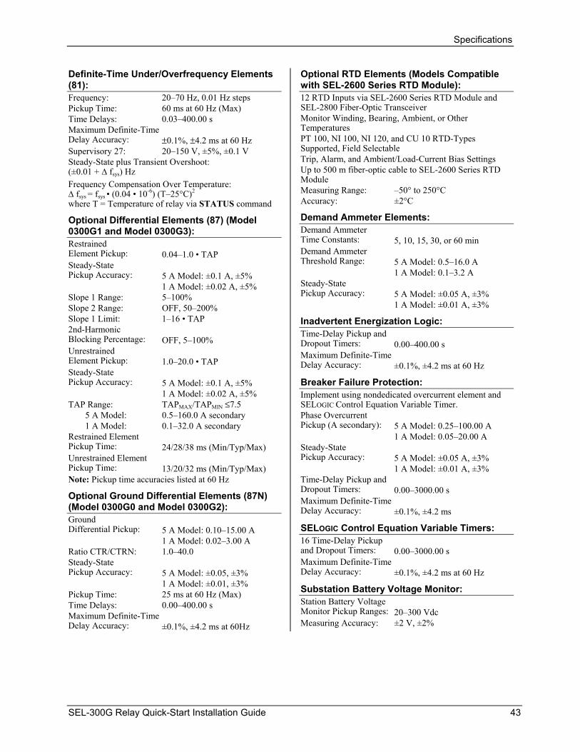
Specifications
Definite-Time Under/Overfrequency Elements (81):
Optional RTD Elements (Models Compatible with SEL-2600 Series RTD Module):
Frequency: 20–70 Hz, 0.01 Hz steps 12 RTD Inputs via SEL-2600 Series RTD Module and SEL-2800 Fiber-Optic Transceiver Pickup Time: 60 ms at 60 Hz (Max) Monitor Winding, Bearing, Ambient, or Other Temperatures
Time Delays: 0.03–400.00 s Maximum Definite-Time Delay Accuracy:
PT 100, NI 100, NI 120, and CU 10 RTD-Types Supported, Field Selectable
±0.1%, ±4.2 ms at 60 Hz Supervisory 27: 20–150 V, ±5%, ±0.1 V
Trip, Alarm, and Ambient/Load-Current Bias Settings Steady-State plus Transient Overshoot: (±0.01 + ∆ f Up to 500 m fiber-optic cable to SEL-2600 Series RTD
Module ) Hz sys
Frequency Compensation Over Temperature: ∆ f Measuring Range: –50° to 250°C -6 2
sys = fsys • (0.04 • 10 ) (T–25°C)Accuracy: ±2°C where T = Temperature of relay via STATUS command Demand Ammeter Elements: Optional Differential Elements (87) (Model
0300G1 and Model 0300G3): Demand Ammeter Time Constants:
5, 10, 15, 30, or 60 min Restrained
Element Pickup:
Demand Ammeter Threshold Range:
0.04–1.0 • TAP 5 A Model: 0.5–16.0 A Steady-State
Pickup Accuracy:
1 A Model: 0.1–3.2 A 5 A Model: ±0.1 A, ±5% Steady-State Pickup Accuracy:
1 A Model: ±0.02 A, ±5% 5 A Model: ±0.05 A, ±3% Slope 1 Range: 5–100% 1 A Model: ±0.01 A, ±3% Slope 2 Range: OFF, 50–200%
Slope 1 Limit: 1–16 • TAP Inadvertent Energization Logic: 2nd-Harmonic Blocking Percentage:
Time-Delay Pickup and Dropout Timers:
OFF, 5–100% 0.00–400.00 s
Unrestrained Element Pickup:
Maximum Definite-Time Delay Accuracy:
1.0–20.0 • TAP ±0.1%, ±4.2 ms at 60 Hz
Steady-State Pickup Accuracy:
Breaker Failure Protection: 5 A Model: ±0.1 A, ±5%
1 A Model: ±0.02 A, ±5% Implement using nondedicated overcurrent element and SELOGIC Control Equation Variable Timer. TAP Range: TAPMAX/TAPMIN ≤7.5
5 A Model: 0.5–160.0 A secondary Phase Overcurrent Pickup (A secondary):
1 A Model: 0.1–32.0 A secondary 5 A Model: 0.25–100.00 A Restrained Element Pickup Time:
1 A Model: 0.05–20.00 A 24/28/38 ms (Min/Typ/Max) Steady-State
Pickup Accuracy:
Unrestrained Element Pickup Time:
5 A Model: ±0.05 A, ±3% 13/20/32 ms (Min/Typ/Max) 1 A Model: ±0.01 A, ±3%
Note: Pickup time accuracies listed at 60 Hz Time-Delay Pickup and Dropout Timers:
0.00–3000.00 s Optional Ground Differential Elements (87N)
(Model 0300G0 and Model 0300G2): Maximum Definite-Time Delay Accuracy:
±0.1%, ±4.2 ms
Ground Differential Pickup:
SELOGIC Control Equation Variable Timers: 5 A Model: 0.10–15.00 A 16 Time-Delay Pickup and Dropout Timers:
1 A Model: 0.02–3.00 A 0.00–3000.00 s Ratio CTR/CTRN: 1.0–40.0
Maximum Definite-Time Delay Accuracy:
Steady-State Pickup Accuracy:
±0.1%, ±4.2 ms at 60 Hz 5 A Model: ±0.05, ±3%
1 A Model: ±0.01, ±3% Substation Battery Voltage Monitor: Pickup Time: 25 ms at 60 Hz (Max) Station Battery Voltage Monitor Pickup Ranges:
Time Delays: 0.00–400.00 s 20–300 Vdc Maximum Definite-Time
Delay Accuracy:
Measuring Accuracy: ±2 V, ±2% ±0.1%, ±4.2 ms at 60Hz
SEL-300G Relay Quick-Start Installation Guide 43

Specifications
Metering Accuracy: Accuracies are specified at 20°C and at nominal system frequency unless noted otherwise.
Voltages VA, VB, V , VC NB , V , 3V , V , V , VS 0 1 2 AB, V
, VBC CA: ±0.1% (33.5–218.0 V)
Currents IA, IB, I : 5 A Nominal: ±1 mA or ±0.1% (0.5–10.0 A)
CB
1 A Nominal: ±0.2 mA or ±0.1% (0.1–2.0 A)
2Temperature coefficient: [(0.0002%)/(°C) ] * (__°C –20°C)2 (see example below) ±0.5° Phase Angle Accuracy: Currents IN, I , IA87 B87,
IC87, I , 3I , 3I : 5 A Nominal: ±0.05 A or ±3% (0.5–100.0 A)
1 0 2
1 A Nominal: ±0.01 A or ±3% (0.1–20.0 A)
MW / MVAR (A, B, C, and 3-phase; 5 A nominal; wye-connected voltages): Accuracy (MW / MVAR)
at load angle
for 0.5 A ≤ phase current < 1.0 A: 0.70% / – 0° or 180° (unity power factor) 0.75% / 6.50% ±8° or ±172° 1.00% / 2.00% ±30° or ±150° 1.50% / 1.50% ±45° or ±135° 2.00% / 1.00% ±60° or ±120° 6.50% / 0.75% ±82° or ±98° – / 0.70% ±90° (power factor = 0) for phase current ≥ 1.0 A : 0.35% / – 0° or 180° unity power factor) 0.40% / 6.00% ±8° or ±172° 0.75% / 1.50% ±30° or ±150° 1.00% / 1.00% ±45° or ±135° 1.50% / 0.75% ±60° or ±120° 6.00% / 0.40% ±82° or ±98° – / 0.35% ±90° (power factor = 0) Metering accuracy calculation example for currents IA, IB, and I due to preceding stated temperature coefficient: CFor temperature of 40°C, the additional error for currents IA, IB, and I is: C
2 2[(0.0002%)/(°C) ] * (40°C –20°C) = 0.08%
44 SEL-300G Relay Quick-Start Installation Guide

Differential Element Commissioning WorksheetEIA-232 Serial Port Voltage Jumpers
DIFFERENTIAL ELEMENT COMMISSIONING WORKSHEET
Date: Installer:
RELAY ID (RID):
TERMINAL ID (TID):
CTR = CTRD = E87 = TRCON = CTCON =
With load applied to the relay, use the front panel METER Inst function to find the current quantities (magnitude and phase angle) and the three-phase power quantities:
IA = IA87 = IB = IB87 = IC = IC87 =
Next, use the METER DIF function to find the differential operate, in percent of restraint:
IOP1 = % of restraint IOP2 = % of restraint IOP3 = % of restraint
If all three operate quantities are less than 10 percent of restraint, then the relay is installed correctly.
If IOP1, IOP2 or IOP3 is greater than 10 percent, there may be a connection, CT ratio, or setting error. Perform the following additional checks:
1. Plot the six measured currents in the chart on the Check List. Verify correct phase rotation for both sets of three currents. Correct any problems found and recheck the operate quantities to determine if they are less than 10 percent.
2. Based on the relay settings and the chart notations, verify the desired phase angle difference between the phase current inputs and the differential current inputs. Correct any problems found and recheck the operate quantities to determine if they are less than 10 percent.
3. Steps 1 and 2 address possible CT connection errors. If IOP > 10 percent remains on a single phase, check the CT tap connections of the affected phase to verify that the relay is connected to the appropriate CT tap, per the CTR and CTRD settings. If mismatch remains on all three phases, check the CTR and CTRD settings to ensure that they are correct, per the actual CT ratio.
SEL-300G Relay Quick-Start Installation Guide 45

Differential Element Commissioning Worksheet
Check List 1. Phasor rotation is as expected.
2. Circle your transformer and CT connection:
If E87 = G, OR
If E87 = T AND TRCON = GEN, CTCON = Y TRCON = DABY, CTCON = DAB Plot Phasors TRCON = YDAB, CTCON = Y TRCON = DACY, CTCON = DAC
135
90
45
180/-180
-135
-90
-45
0
DWG: MAPP-E
TRCON = YDAC, CTCON = Y TRCON = DABDAB, CTCON = Y TRCON = DACDAC, CTCON = Y TRCON = YY, CTCON = Y
Then, phase angles should be 180° apart.
If E87 = T AND TRCON = GEN, CTCON = DAC TRCON = DABY, CTCON = Y TRCON = YDAC, CTCON = Y
Then, I87 should lead IW1 by 150°.
If E87 = T AND TRCON = GEN, CTCON = DAB TRCON = DACY, CTCON = Y TRCON = YDAB, CTCON = Y
Then, I87 should lag IW1 by 150°.
46 SEL-300G Relay Quick-Start Installation Guide