300kva guide specification - toshiba · an optional manual make-before-break maintenance bypass...
TRANSCRIPT

CORPORATE OFFICE 13131 WEST LITTLE YORK ROAD HOUSTON, TX 77041 PHONE: (713) 466-0277 (800) 231-1412 FACSIMILE: (713) 896-5226
G8000GS – Rev. 003
1
TOSHIBA G8000
80/100/150/225/300 kVA
GUIDE SPECIFICATION
THREE PHASE UNINTERRUPTIBLE POWER SUPPLY
July 2009

2

3
Table of Contents
1 SCOPE ........................................................................................................................................................... 5
1.1 System ............................................................................................................................................................. 5
2 SYSTEM DESCRIPTION ................................................................................................................................... 5
2.1 Applicable Standards ....................................................................................................................................... 5
2.2 Components .................................................................................................................................................... 5
2.3 System Operation ............................................................................................................................................ 6
3 GENERAL CONDITIONS FOR INSTALLATION ................................................................................................... 6
3.1 Required Input Capacity: ................................................................................................................................. 6
3.2 Grounding System: .......................................................................................................................................... 6
3.3 UPS Environment ............................................................................................................................................. 7 3.3.1 Standard Environmental Parameters ..................................................................................................... 7 3.3.2 Discharge Heat from UPS at full load. .................................................................................................... 7 3.3.3 Clearances for installation ..................................................................................................................... 7 3.3.4 Cable Access ........................................................................................................................................... 7
4 SYSTEM PARAMETERS .................................................................................................................................. 7
4.1 UPS Requirements: .......................................................................................................................................... 7
4.2 AC Input: .......................................................................................................................................................... 8
4.3 Charging Function: .......................................................................................................................................... 8
4.4 Static Bypass: ................................................................................................................................................... 9
4.5 Bypass:Input .................................................................................................................................................... 9
4.6 AC Output: ....................................................................................................................................................... 9
5 FUNCTIONAL DESCRIPTION ......................................................................................................................... 10
5.1 Diode Rectifier ............................................................................................................................................... 10 5.1.1 General ................................................................................................................................................ 10 5.1.2 Voltage Regulation ............................................................................................................................... 10 5.1.3 Reflected Harmonic Content ............................................................................................................... 10
5.2 IGBT DC-DC Converter ................................................................................................................................... 10 5.2.1 General ................................................................................................................................................ 10 5.2.2 Battery Charge Current Limit ............................................................................................................... 11 5.2.3 Battery Charge Current Limit ............................................................................................................... 11 5.2.4 Battery Protection ............................................................................................................................... 11 5.2.5 DC Ripple .............................................................................................................................................. 11
5.3 IGBT Inverter: ................................................................................................................................................. 11 5.3.1 General ................................................................................................................................................ 11 5.3.2 Output Voltage .................................................................................................................................... 11
4
5.3.3 Synchronization ................................................................................................................................... 12 5.3.4 Output Control ..................................................................................................................................... 12 5.3.5 Overload Capacity: ............................................................................................................................... 12
5.4 Battery Protection ......................................................................................................................................... 12 5.4.1 UPS operation ...................................................................................................................................... 12
5.5 Static Bypass Circuit: ..................................................................................................................................... 12 5.5.1 General: ............................................................................................................................................... 12 5.5.2 Overload Capacity: ............................................................................................................................... 13 5.5.3 Retry function: ..................................................................................................................................... 13
5.6 Metering, Monitoring, Alarms and Controls ................................................................................................. 14 5.6.1 Status Indicators ................................................................................................................................. 14 5.6.2 Mimic Panel ......................................................................................................................................... 14 5.6.3 Isolated Contact Signals ....................................................................................................................... 14
6 MECHANICAL DESIGN ................................................................................................................................. 15
6.1 UPS Enclosure ................................................................................................................................................ 15
6.2 Cable Access .................................................................................................................................................. 15
7 WARRANTY ................................................................................................................................................. 15
7.1 UPS Warranty ................................................................................................................................................ 15
7.2 UPS Battery Warranty ................................................................................................................................... 15
7.3 Warranty Support Availability ....................................................................................................................... 15
8 BATTERY CABINETS (OPTION) ..................................................................................................................... 15
9 COMMUNICATIONS (OPTIONAL)................................................................................................................. 15
9.1 RemotEye II Network Adapter ....................................................................................................................... 15 9.1.1 SNMP Ability ........................................................................................................................................ 16 9.1.2 HTTP Familiarity ................................................................................................................................... 16 9.1.3 Shutdown Capability ............................................................................................................................ 16
9.2 Remote Status Alarm Panel (RSAP) ............................................................................................................... 17
10 TOSHIBA DISTRIBUTION CABINET (TDC) (OPTION) ...................................................................................... 17
11 MAINTENANCE BYPASS PANEL (OPTION) .................................................................................................... 17
11.1 Site Installation ......................................................................................................................................... 17
11.2 Electrical Configuration ............................................................................................................................ 17
11.3 Mechanical Interlock ................................................................................................................................ 17
11.4 External Maintenance Bypass: ................................................................................................................. 17
12 AUXILIARY TRANSFORMER CABINETS (OPTION) ......................................................................................... 18
13 POWER DISTRIBUTION UNITS (OPTION) ...................................................................................................... 18
14 EXTENDED SERVICES (OPTION) ................................................................................................................... 18

5
1 SCOPE
1.1 System
These specifications describe a continuous duty, three-phase, on-line, solid-state
Uninterruptible Power Supply system, hereafter referred to as the UPS. The UPS shall
operate utilizing the existing power distribution system to provide high quality,
uninterruptible power to critical loads.
The UPS shall consist of an AC/DC Rectifier, DC/DC Converter/Battery Charger,
DC/AC IGBT Inverter, integral static bypass, front-accessible controls, display, and
monitor.
2 SYSTEM DESCRIPTION
2.1 Applicable Standards
The UPS shall be designed in accordance with and be compliant with the following
sections of the current revisions of the following standards:
UL 1778 Listed
FCC Class A, Article 47, Part 15.B
ISO 9001
ANSI C62.41 (IEEE 587) – Standard for Surge Withstandability
IEC (International Electrotechnical Commission)
National Electrical Code (NFPA-70)
NEMA PE-1
OSHA
ASME
2.2 Components
The UPS shall consist of the following components:
1. Diode Rectifier + IGBT Converter
2. Input filter
3. IGBT Inverter
4. Inverter Output Isolation Transformers
5. Hybrid Integral Static Bypass (Thyristor Switch with wrap around contactor)
6. Microprocessor Controlled Logic and Control Panel
The following components shall be optional:
1. Input Isolation Transformers
2. Battery Cabinet with DC Breaker
3. Toshiba Distribution Cabinet (TDC)
4. Maintenance Bypass Panel (Circuit Breaker)
5. RemotEye II UPS remote communications and web-based monitor card

6
6. Network communications with MODBUS interface adapter
7. Remote Status Alarm Panel (RSAP)
2.3 System Operation
The UPS shall operate as a fully automatic on-line system in the following modes:
1. Normal:
Diode Rectifier and IGBT Converter converts AC input power to DC power for the
inverter and charging the batteries. The UPS Inverter output shall be synchronized
with the bypass AC source when the bypass source is within the AC input voltage
and frequency specifications.
2. Loss of Main Power
When Main Power is lost, the battery option shall automatically back up the
inverter so there is no interruption of AC power to the critical load.
3. Return of Main Power
The system shall recover to the operating mode in Item 1 and shall cause no
disturbance to the critical load while simultaneously recharging the backup battery.
4. Transfer to Bypass AC source
If the UPS becomes overloaded, or an internal fault is detected, the UPS controls
shall automatically transfer the critical load from the inverter output to the bypass
AC source without interruption. When the overload or internal warning condition
is removed, after a preset “hold” period the UPS will automatically re-transfer the
critical load from the bypass to the inverter output without interruption of power to
the critical load.
5. Maintenance Bypass/Test Mode
An optional manual make-before-break maintenance bypass panel may be provided
to electrically isolate the UPS for maintenance or test without affecting load
operation.
3 GENERAL CONDITIONS FOR INSTALLATION
3.1 Required Input Capacity:
The UPS will be available in the following output capacities: 80, 100, 150, 225, and 300
kVA (80, 100, 150, 225, and 300 kW).
3.2 Grounding System:
A. Ground wiring with grounding resistance less than 10 ohms shall be supplied for
the UPS.
B. It is necessary for the load to be grounded to the same ground point as the UPS,
and the ground wiring shall be for the exclusive use of the UPS and load.
7
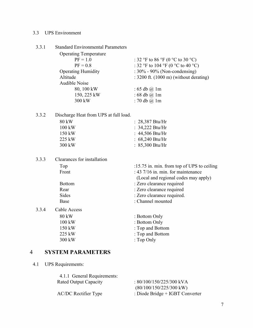
3.3 UPS Environment
3.3.1 Standard Environmental Parameters
Operating Temperature
PF = 1.0 : 32 °F to 86 °F (0 °C to 30 °C)
PF = 0.8 : 32 °F to 104 °F (0 °C to 40 °C)
Operating Humidity : 30% - 90% (Non-condensing)
Altitude : 3200 ft. (1000 m) (without derating)
Audible Noise
80, 100 kW : 65 db @ 1m
150, 225 kW : 68 db @ 1m
300 kW : 70 db @ 1m
3.3.2 Discharge Heat from UPS at full load.
80 kW : 28,387 Btu/Hr
100 kW : 34,222 Btu/Hr
150 kW : 44,506 Btu/Hr
225 kW : 68,240 Btu/Hr
300 kW : 85,300 Btu/Hr
3.3.3 Clearances for installation
Top :15.75 in. min. from top of UPS to ceiling
Front : 43 7/16 in. min. for maintenance
(Local and regional codes may apply)
Bottom : Zero clearance required
Rear : Zero clearance required
Sides : Zero clearance required.
Base : Channel mounted
3.3.4 Cable Access
80 kW : Bottom Only
100 kW : Bottom Only
150 kW : Top and Bottom
225 kW : Top and Bottom
300 kW : Top Only
4 SYSTEM PARAMETERS
4.1 UPS Requirements:
4.1.1 General Requirements:
Rated Output Capacity : 80/100/150/225/300 kVA
(80/100/150/225/300 kW)
AC/DC Rectifier Type : Diode Bridge + IGBT Converter

8
DC/AC Inverter Type : IGBT PWM Inverter
External Dimensions : (W) (D) (H)
80 kW : 36.8 in.x 32.5 in. x 79.2 in.
100 kW : 36.8 in.x 32.5 in. x 79.2 in.
150 kW : 55.1 in.x 31.8 in. x 79.2 in.
225 kW : 55.1 in.x 31.8 in. x 79.2 in.
300 kW : 76.8 in.x 33.7 in. x 79.4 in.
Weight Unit Wt. (Shipping Wt.)
80 kW : 1390 lb. (1440 lb.)
100 kW : 1740 lb. (1790 lb.)
150 kW : 2467 lb. (2556 lb.)
225 kW : 2980 lb. (3069 lb.)
300 kW : 4575 lb. (4725 lb.)
Floor Loading
80 kW : 171 lb./ft.2
100 kW : 214 lb./ft.2
150 kW : 203 lb./ft.2
225 kW : 245 lb./ft.2
300 kW : 255 lb./ft.2
Insulation Resistance : 3 M as measured with a 500 V Megger
Insulation Breakdown
Main circuit : 2 kV AC for 1 minute
External Interface : 1.5 kV AC for 1 minute
Control Circuit : 500 V AC for 1 minute
Cabinet Protection Conformity : IEC298 IP20
4.2 AC Input:
Configuration : 3-Phase/3-Wire + Ground
Rated Voltage : 480 V
Voltage Variation : +10% to –15%
Rated Frequency : 60 Hz
Frequency Variation : +/-5%
Input Power Factor : Greater than 0.99 lagging at 100% load
Current THD : < 5% at 100% load
< 6% at 25% load
4.3 Charging Function:
DC Nominal Voltage : 360 V
AC Ripple on DC Bus : < 0.2% of DC Voltage
DC Voltage Range : 288 V to 414 V
DC Float Charging Voltage : 405V
Maximum charging current:
80 kW : 30 A
100 kW : 30 A
160 kW : 30 A
225 kW : 30 A

9
300 kW : 30 A
AC Ripple on DC Charging Circuit :
80 kVA : 0.2%
100 kVA : 0.2%
160 kVA : 0.2%
225 kVA : 0.2%
300 kVA : 0.2%
4.4 Static Bypass:
Rated Voltage (Input) : 480/277 V
Rated Voltage (Output) : 480/277 V
Rated Frequency : 60 Hz
Number of Phases/Wires : 3 Phase/4 Wire
Description : Thyristor Switch + wrap-around contactor
4.5 Bypass:Input
Configuration : 3-Phase/4-Wire + Ground
Rated Voltage : 480/277 V
Input Synchronization Voltage Range : +/-10%
Rated Frequency : 60Hz
Frequency Variation : +/-5.0%
Frequency Synchronous Range : +/-0.5 Hz, +/-1.0 Hz (Selectable)
Bypass Overload Capacity : 1000% for one cycle, 500% for two cycles
4.6 AC Output:
Configuration : 3-Phase/4-Wire + Ground
Rated Capacity : 80/100/150/225/300 kVA
(80/100/150/225/300 kW)
Rated Voltage : 480/277V ± 1%
Effeciency at Full Load
80 kW : 90.6%
100 kW : 91.0%
150 kW : 93.0%
225 kW : 91.9%
300 kW : 92.0%
Voltage Regulation : +/-0.5% (0-100% Balanced Load)
Voltage Adjustment Range : +/-5.0%
Rated Frequency : 60Hz
Frequency Regulation : +/-0.01% (Free-Running Mode)
Frequency Synchronous Range : +/-0.5Hz, +/-1.0Hz
Rated Load Power Factor
PF = 1.0 : 32° to 86 °F (0 to 30 °C)
PF = 0.8 : 32° to 104 °F (0 to 30 °C)
Overload Capacity : 125% for 10 min.,
150% for 1 min.
10
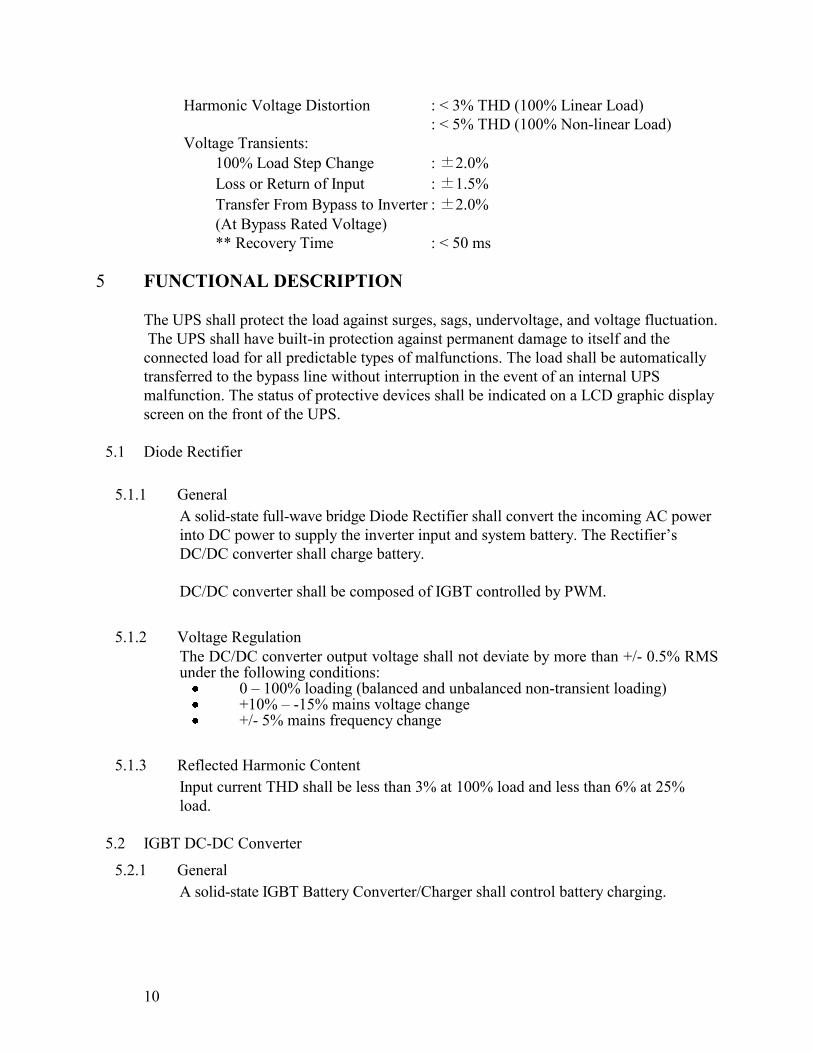
Harmonic Voltage Distortion : < 3% THD (100% Linear Load)
: < 5% THD (100% Non-linear Load)
Voltage Transients:
100% Load Step Change : ±2.0%
Loss or Return of Input : ±1.5%
Transfer From Bypass to Inverter : ±2.0%
(At Bypass Rated Voltage)
** Recovery Time : < 50 ms
5 FUNCTIONAL DESCRIPTION
The UPS shall protect the load against surges, sags, undervoltage, and voltage fluctuation.
The UPS shall have built-in protection against permanent damage to itself and the
connected load for all predictable types of malfunctions. The load shall be automatically
transferred to the bypass line without interruption in the event of an internal UPS
malfunction. The status of protective devices shall be indicated on a LCD graphic display
screen on the front of the UPS.
5.1 Diode Rectifier
5.1.1 General
A solid-state full-wave bridge Diode Rectifier shall convert the incoming AC power
into DC power to supply the inverter input and system battery. The Rectifier’s
DC/DC converter shall charge battery.
DC/DC converter shall be composed of IGBT controlled by PWM.
5.1.2 Voltage Regulation
The DC/DC converter output voltage shall not deviate by more than +/- 0.5% RMS under the following conditions:
0 – 100% loading (balanced and unbalanced non-transient loading) +10% – -15% mains voltage change +/- 5% mains frequency change
5.1.3 Reflected Harmonic Content
Input current THD shall be less than 3% at 100% load and less than 6% at 25%
load.
5.2 IGBT DC-DC Converter
5.2.1 General
A solid-state IGBT Battery Converter/Charger shall control battery charging.

11
5.2.2 Battery Charge Current Limit
The Converter logic shall provide DC battery current limiting for controlled battery charging. The battery current sensing shall be independent of the Converter DC output current sensing to provide precise battery recharging. The DC/DC Charging Converter shall include a circuit to limit battery-charging current to an adjustable level of 100% to 125% of maximum battery charging current.
5.2.3 Battery Charge Current Limit
The Converter logic shall provide DC for controlled battery charging. The battery
current sensing shall be independent of the Converter DC Output current sensing to
provide precise battery recharging control. The DC/DC Charging Converter shall
include a circuit to regulate the battery charging current to between 100% and
125%.
5.2.4 Battery Protection
The converter shall be provided with monitoring and control circuits to protect the
battery system from damage due to excessive discharge. Converter shutdown shall
be initiated when the battery voltage reaches a discharge cutoff voltage of 277 VDC.
Automatic shutdown based on discharge time is not acceptable.
5.2.5 DC Ripple
AC Ripple on the DC Bus shall be less than 0.2%.
5.3 IGBT Inverter:
5.3.1 General
For increased performance the inverter shall be composed of IGBT power
transistors controlled utilizing a pulse-width-modulation (PWM) design.
The Inverter shall continuously convert DC power from the Diode Rectifier to AC
power for the critical loads. When the utility voltage or frequency exceeds the
specified UPS input tolerances, the inverter shall continuously convert DC power
from the battery source to AC power for the critical load.
The inverter shall be capable of providing rated output while operating at any
battery voltage within the battery operating range. When the DC battery voltage
reaches the operational low voltage limit during a loss of utility AC power, the
inverter shall automatically shut off.
5.3.2 Output Voltage
The Inverter output voltage shall not deviate by more than +/- 1.0% RMS under the following steady state conditions as the Inverter DC input varies from :
0% to 100% Unbalanced load 0% to 100% Unbalanced load
12
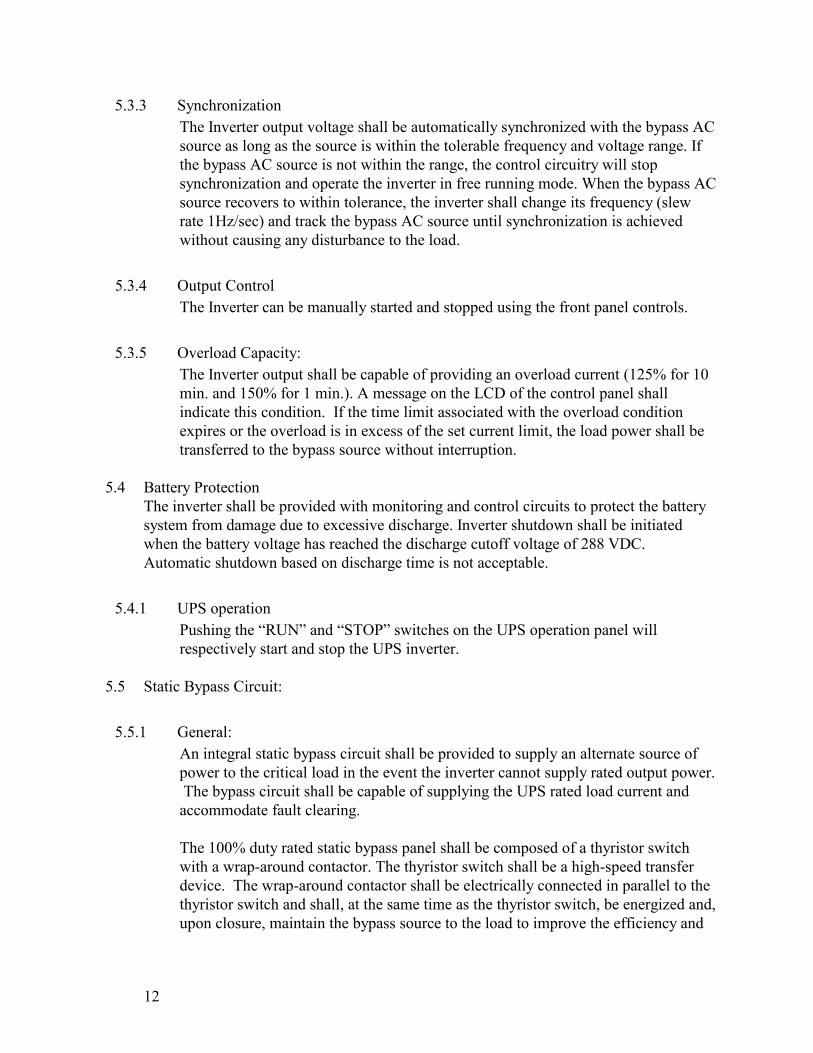
5.3.3 Synchronization
The Inverter output voltage shall be automatically synchronized with the bypass AC
source as long as the source is within the tolerable frequency and voltage range. If
the bypass AC source is not within the range, the control circuitry will stop
synchronization and operate the inverter in free running mode. When the bypass AC
source recovers to within tolerance, the inverter shall change its frequency (slew
rate 1Hz/sec) and track the bypass AC source until synchronization is achieved
without causing any disturbance to the load.
5.3.4 Output Control
The Inverter can be manually started and stopped using the front panel controls.
5.3.5 Overload Capacity:
The Inverter output shall be capable of providing an overload current (125% for 10
min. and 150% for 1 min.). A message on the LCD of the control panel shall
indicate this condition. If the time limit associated with the overload condition
expires or the overload is in excess of the set current limit, the load power shall be
transferred to the bypass source without interruption.
5.4 Battery Protection
The inverter shall be provided with monitoring and control circuits to protect the battery
system from damage due to excessive discharge. Inverter shutdown shall be initiated
when the battery voltage has reached the discharge cutoff voltage of 288 VDC.
Automatic shutdown based on discharge time is not acceptable.
5.4.1 UPS operation
Pushing the “RUN” and “STOP” switches on the UPS operation panel will
respectively start and stop the UPS inverter.
5.5 Static Bypass Circuit:
5.5.1 General:
An integral static bypass circuit shall be provided to supply an alternate source of
power to the critical load in the event the inverter cannot supply rated output power.
The bypass circuit shall be capable of supplying the UPS rated load current and
accommodate fault clearing.
The 100% duty rated static bypass panel shall be composed of a thyristor switch
with a wrap-around contactor. The thyristor switch shall be a high-speed transfer
device. The wrap-around contactor shall be electrically connected in parallel to the
thyristor switch and shall, at the same time as the thyristor switch, be energized and,
upon closure, maintain the bypass source to the load to improve the efficiency and

13
reliability of the system. The thyristor switch shall only be utilized for the time
needed to energize the contactor closure.
The UPS system logic shall employ sensing which shall cause the thyristor switch to
energize and provide an uninterrupted transfer of the load to the bypass source when
any of the following limitations are exceeded:
Inverter output undervoltage or overvoltage.
Overloads exceeding 125% for 10 min., or 150% for 1 min.
DC circuit undervoltage or overvoltage.
Final discharge voltage of system battery is reached and the bypass source
is present, available, and within tolerance range
Transferring the output from the inverter to the bypass source and vice versa will be
performed by pressing "BYPASS" and "UPS" switches on the operation panel.
Operating
Mode Transfer mode
Transfer Type
Synchronized Unsynchronized
Automatic Inverter to Bypass
(Overload, Internal Fault) Uninterrupted Interrupted
“BYPASS”
switch operated Inverter to Bypass Uninterrupted
Interrupted
(forced transfer)
Automatic Bypass to Inverter
(Auto-Retransfer Mode) Uninterrupted Transfer inhibited
“UPS”
switch operated Bypass to Inverter Uninterrupted Transfer inhibited
If the bypass source is beyond the conditions stated below, interrupted transfer shall be
made upon detection of a fault condition.
Bypass voltage greater than +/- 10% from the UPS rated output voltage.
Bypass frequency greater than + 1 Hz from the UPS rated output frequency.
5.5.2 Overload Capacity:
Continuous duty : 125% of the system rated capacity
Overload duty : 1000% of ampere rating for greater than 1 cycle.
5.5.3 Retry function:
When an internal warning has been detected, power flow shall automatically switch
from the main circuit (inverter) to the bypass circuit without interruption to the load.
If the internal warning is cleared, UPS shall automatically switch the power flow
from the bypass circuit to the main circuit (inverter) without interruption.

14
5.6 Metering, Monitoring, Alarms and Controls
5.6.1 Status Indicators
The Front Panel shall have a 4-line liquid crystal display (LCD) screen. The 4-line
LCD screen shall display selected performance data, statistics, and operating
conditions. The following metering will be displayed on LCD screen:
AC Input Voltage
AC Output Voltage
DC Voltage
DC Current
Output Current
Output Frequency
5.6.2 Mimic Panel
The UPS shall have a one-line diagram of the system on the control and monitor
panels to provide a visual display of the status of circuit breakers within UPS. There
shall be a keypad with 8 keys on the graphic display panel. The 8 keys allow easy
operation of the UPS.
The mimic panel shall display the active/inactive status of the following:
AC Input, DC Input
Converter in Operation
Inverter in Operation
UPS/Bypass supply
Battery Operating Condition (Float Charge/Equal Charge/Discharge)
Fault, Warning
Operation Guidance (LCD Display)
Fault Guidance (LCD Display)
5.6.3 Isolated Contact Signals
Form “A” isolated contact signal outputs for remote use shall be furnished for the
following operating status indications:
Inverter Operation
Battery Operation
Battery Voltage Drop
Bypass Supply
Warning
Fault
Contact ratings: 1A/120VAC, 1A/24VDC, 0.1A/120VDC (resistive).
Isolated contact signal inputs shall be furnished for the following remote operations:
Remote Start, Remote Stop, Remote Emergency Power Off (EPO).
The contact signal inputs and outputs shall be wired to a terminal block located
inside the UPS.

15
6 MECHANICAL DESIGN
6.1 UPS Enclosure
The UPS shall be freestanding, front access, NEMA1 enclosure equipped with a leveling
channel base. The enclosure shall include provisions for hoisting, jacking, and forklift
handling.
6.2 Cable Access
Cable access to the UPS shall be
80 kW :Bottom entry only
100 kW :Bottom entry only
150 kW : Top and Bottom entry
225 kW : Top and Bottom entry
300 kW : Top entry only.
7 WARRANTY
7.1 UPS Warranty
The UPS shall come with a 36-month warranty on all mechanical, electrical, electronic
components. Parts, labor, and travel are included during warranty period. Optional
extended warranties shall be available.
7.2 UPS Battery Warranty
The back-up batteries shall come with a ten-year warranty: three years full, then seven
years pro rata. Parts, labor, and travel are included during warranty period. Optional
extended warranties shall be available. See Toshiba warranties at www.toshiba.com/ind
7.3 Warranty Support Availability
Warranty and technical support shall be available 24/7/365. (877-867-8773)
8 BATTERY CABINETS (OPTION)
The UPS manufacturer can provide optional matching battery cabinets with DC breaker.
9 COMMUNICATIONS (OPTIONAL)
9.1 RemotEye II Network Adapter
The UPS shall provide either an internal or external support for the internet web/SNMP
adapter RemotEye II for the optional capability of remote or internet system monitoring.

16
9.1.1 SNMP Ability
RemotEye II shall provide a SNMP interface for the UPS. The SNMP interface
shall provide for easy integration of UPS management into an existing SNMP
Network Management System. At any given time, SNMP queries shall be able to
poll the RemotEye II agent for the current status of its connected UPS.
9.1.2 HTTP Familiarity
The RemotEye II shall provide a HTTP interface for the UPS to allow easy access
of the UPS information from any machine with a web browser. At any time, a
network workstation or management station shall be able to open a RemotEye II
website. RemotEye II website shall enable the UPS system information to be
configured and monitored remotely. RemotEye II shall provide access to 3 java
applets for monitoring, event logging, and trend analysis.
9.1.3 Shutdown Capability
The RemotEye II application software shall allow RemotEye II to remotely notify
and shutdown selected network servers.
Network Adapter/External Hardware
AMD 188ES-20MHz
512kB SRAM: 512kB Flash
Two asynchronous serial ports
10 BaseT RJ-45 connector
Toshiba UPS communication protocol
SNMP over UDP/IP : HTTP over TCP/IP:ARP, RARP, TFTP and
ICMP
MIB_II : Toshiba v1.2_MIB :JEM MIB : RFC 1628
Traffic LED for network : Status LED for status : Power LED for
Power
2 digit (default setting is Switches 1 and 2 off)
Temperature Range: 0 – 40 C
Relative Humidity: 10 – 80 %
Power Requirements: 12 VDC ungrounded
2.0 Watts Maximum
Dimensions: 5.28”(134mm) x 3.40”(86mm) x 1.10”(27mm) (LxWxH)
Weight: 0.38lbs(170g)
Certifications: FCC class A, UL, CUL, CE

17
9.2 Remote Status Alarm Panel (RSAP)
The manufacturer shall optionally provide a RSAP that shall provide a wall-mounted
LED mimic display for UPS status events of:
Input ON
Bypass ON
Inverter ON
Low Battery, AC Fail
New alarm annunciation
Battery backup for the RSAP monitor.
10 TOSHIBA DISTRIBUTION CABINET (TDC) (OPTION)
The manufacturer can optionally provide a matching TDC for the UPS.
The TDC can include a step-down, 480/208/120 V transformer in a matching
NEMA1 cabinet.
The TDC can include a three-breaker MBS with a slidebar interlock. Interlock
keys and Solenoid Key-Retractable Unit (SKRU) can be provided.
The TDC can include up to eight 225 A sub-feed breakers.
The TDC can include up to two 42-pole distribution panels.
11 MAINTENANCE BYPASS PANEL (OPTION)
The manufacturer can optionally provide a MBS (Maintenance Bypass Panel) for the
UPS.
11.1 Site Installation
The MBS can be available in either a wall mount or floor mount configuration.
11.2 Electrical Configuration
The MBS can be available in two, three, or four breaker configurations.
11.3 Mechanical Interlock
The MBS can have the option for a two-kirk-key interlock system.
11.4 External Maintenance Bypass:
A manually operated maintenance bypass panel can be provided to bypass the
power feeding the critical load from inverter to a static switch panel without
causing any power interruption.
Bypass input breaker can supply input power to the UPS module static bypass
input. If the system design calls for separate UPS and bypass inputs, a bypass
input breaker can be installed on each input.
UPS maintenance bypass breaker can allow power flow to the load when the UPS
is bypassed. This can be a normally open circuit breaker.
The UPS module output can feed the UPS output isolation breaker.
18
Optionally, the two input bypass breaker can be used to feed both the UPS
converter input and the UPS bypass input.
12 AUXILIARY TRANSFORMER CABINETS (OPTION)
The UPS manufacturer can provide optional Auxiliary Transformer Cabinets (ATC) for
stepping the UPS output voltage down to service load voltages.
13 POWER DISTRIBUTION UNITS (OPTION)
The UPS manufacturer shall provide optional PDUs (Power Distribution Units) for
stepping the UPS output voltage down to service load voltages. The PDUs can be
provided in either front-access cabinet or Rack-mount style.
14 EXTENDED SERVICES (OPTION)
The UPS manufacturer can offer :
Startup Service
Maintenance Contracts (Silver, Gold, Platinum)
Preventive Maintenance Contracts
Spare-parts kits (A, B, and C level)
Extended warranty coverage for up to an additional 5 years
Enhanced warranty contract (24/7 + Holiday coverage)
Load bank testing
Factory witness testing
Site monitor and power audits