304 ieee transactions on circuits and systems …users.ics.forth.gr/~zabulis/b6.pdf · stereo-based...
TRANSCRIPT
304 IEEE TRANSACTIONS ON CIRCUITS AND SYSTEMS FOR VIDEO TECHNOLOGY, VOL. 14, NO. 3, MARCH 2004
Stereo-Based Environment Scanningfor Immersive Telepresence
Jane Mulligan, Xenophon Zabulis, Nikhil Kelshikar, and Kostas Daniilidis, Member, IEEE
Abstract—The processing power and network bandwidthrequired for true immersive telepresence applications are onlynow beginning to be available. We draw from our experiencedeveloping stereo based tele-immersion prototypes to present themain issues arising when building these systems. Tele-immersionis a new medium that enables a user to share a virtual spacewith remote participants. The user is immersed in a renderedthree-dimensional (3-D) world that is transmitted from a remotesite. To acquire this 3-D description, we apply binocular andtrinocular stereo techniques which provide a view-independentscene description. Slow processing cycles or long network latenciesinterfere with the users’ ability to communicate, so the densestereo range data must be computed and transmitted at high framerates. Moreover, reconstructed 3-D views of the remote scenemust be as accurate as possible to achieve a sense of presence.We address both issues of speed and accuracy using a variety oftechniques including the power of supercomputing clusters anda method for combining motion and stereo in order to increasespeed and robustness. We present the latest prototype acquiringa room-size environment in real time using a supercomputingcluster, and we discuss its strengths and current weaknesses.
Index Terms—Stereo vision, tele-immersion, telepresence, teras-cale computing.
I. INTRODUCTION
H IGH-SPEED desktop computers, digital cameras, and In-ternet2 connections are making collaboration via immer-
sive telepresence a real possibility. The missing link is currentlythe techniques to extract, transmit, and render the informationfrom sensors at a remote sight such that the local user has thecompelling sense of “being there.” Over the past six years, re-searchers in the GRASP Laboratory at the University of Penn-sylvania have worked with the National Tele-immersion Initia-tive [1] to provide real-time three-dimensional (3-D) stereo re-constructions of remote collaborators for immersive telepres-ence systems. In this paper, we report our progress on the mostimportant aspect of tele-immersion: the ability to acquire dy-namic 3-D scenes in real time.
Manuscript received January 20, 2003; revised April 9, 2003. Thiswork was supported by the National Science Foundation under GrantNSF-IIS-0083209, Grant NSF-EIA-0218691, Grant NSF-IIS-0121293, andGrant NSF-EIA-9703220, by DARPA/ITO/NGI through a subcontract fromthe University of North Carolina, and by a Penn Research Foundation grant.
J. Mulligan is with the Department of Computer Science, University ofColorado at Boulder, Boulder, CO 8030 USA (e-mail: [email protected]).
N. Kelshikar, X. Zabulis, and K. Daniilidis are with the Departmentof Computer and Information Science, University of Pennsylvania,Philadelphia, PA 19104-6389 USA (e-mail: [email protected];[email protected]; [email protected]).
Digital Object Identifier 10.1109/TCSVT.2004.823390
Any form of telepresence needs to convey information abouta remote place to the local user, in an immediate and compellingmanner. Both real-time update and visual quality are necessaryconditions for effective remote collaboration. A remote scenehas to be acquired in real time with as much real-world detailas possible. The need for using real images has been widelyrecognized in computer graphics, and image-based rendering isnow an established area in vision and graphics.
For tele-immersion, we decided to follow a view-independentscene acquisition approach in order to decouple the renderingrate from the acquisition rate and network delays. View inde-pendence allows us to transmit the same 3-D model to manyparticipants in a virtual meeting place, providing each immer-sive display with a model to rerender as the viewer moves withinher augmented display. We have chosen to use dense normalizedcorrelation stereo to capture 3-D data in order to provide denseand accurate view-independent models for rendering in the im-mersive display. A true, detailed 3-D model is also important forinteraction with objects in the 3-D space.
In our extensive experience with tele-immersion prototypes,we have explored many aspects of capturing desktop androom-size environments using dense correlation stereo. Issuesfrom calibrating many cameras in a large volume to how toplace cameras for best accuracy in reconstruction arise in con-structing working systems. We have also explored many of thepossible speed–quality tradeoffs for stereo-based environmentscanning including quantitative comparison to ground truthdata for many aspects of our systems [2], [3].
Obviously, in this age of ever increasing CPU speed, oneway to improve the speed of depth acquisition is to applymore cycles. Our latest prototype does exactly this, utilizingthe power of the Pittsburg Supercomputing Center (PSC)to achieve room-size reconstructions from many 640 480images at high frame rates. Another avenue we are exploring,in order to improve the temporal performance of reconstructionon an image sequence, is to take advantage of temporal coher-ence. Since the same objects tend to be visible from frame toframe—background walls and furniture stay static—we canuse knowledge from earlier frames when processing new ones.However, as usual, there is a complicated tradeoff betweenthe calculation we add for disparity segmentation and motionestimation, and the advantages of predicting disparity rangesfor simplifying the stereo correspondence problem.
This paper summarizes the evolution of an immersive telep-resence system and presents the highlights of today’s version.The main contribution of our approach to the state of the art isin the combination of following points.
1051-8215/04$20.00 © 2004 IEEE
MULLIGAN et al.: STEREO-BASED ENVIRONMENT SCANNING FOR IMMERSIVE TELEPRESENCE 305
• It is the first integrated 3-D remote telepresence systemcomprising geographically distributed image acquisition,3-D computation, and display.
• It is the first stereo system that works in a wide areawithout any background subtraction, implemented in realtime using a supercomputer.
• We propose a temporal prediction process which de-creases disparity search range on segmented imageregions for faster stereo correspondence.
The remainder of the paper is organized as follows: We con-tinue this section with an overview of telepresence, underlyingchallenges in acquisition, and related systems. In Section II, wereview the evolution of our working tele-immersion prototypes.In Section III, we present the details of our stereo algorithm. InSection IV, we describe an experimental evaluation focusing onthe effects of kernel size and view misregistration. In Section V,we propose prediction and motion-depth modeling to optimizethe disparity range search.
A. Telepresence Systems
Telepresence systems can generally be viewed as composedof three parts: a capture system to record and represent the in-formation from the remote site, a network transmission system,and a display system to make the local user feel as if she weresomehow present in the remote scene. These three parts becomeeven more challenging if we require telepresence to be immer-sive, which means to create the illusion of being in an environ-ment different than the viewer’s true physical surroundings.
The first question is, how do we capture representations of theremote scene that are adequate for the task of creating a believ-able remote presence? We have chosen view-independent 3-Dacquisition with correlation-based stereo because it is fast andnoninvasive. The representation has to be view-independent sothat rendering can be decoupled and thus asynchronous to acqui-sition. A second advantage of view independence is that an ac-quired 3-D representation can be broadcast to several receivers.In contrast, a view-dependent approach requires either sendingall images to the remote site where the novel view is computedor computing views locally and transmitting them. In the lattercase, receiving feedback about the user’s head position throughthe network would cause an unmitigated latency.
There are two alternative approaches in remote immersiontechnologies we did not follow. The first involves video con-ferencing in the large: surround projection of two-dimensional(2-D) panoramic images. This requires only a correct alignmentof several views, but lacks the sense of depth and practically for-bids any 3-D interaction with virtual/real objects. The secondtechnology [4] uses 3-D graphical descriptions of the remoteparticipants (avatars). This is just another view of the model-freeversus model-based extrema in the 3-D description of scenes orthe bottom-up versus top-down controversy. Assuming that wehave to deal with persons, human models might be applied [5]combined with image-based rendering, but everything in a scenehas to be scanned prior to a telepresence session and fine de-tail is still missing. Of course, errors in model-based approachestake the form of outlier poses of the avatar, as opposed to outlierdepth points or holes in stereo.
The networking aspects of telepresence systems are just be-ginning to be defined. If there is communication and interactioninvolved, then latency is the most critical issue. Bandwidth af-fects the frame arrival rate. If a lossy protocol is applied, weneed techniques to recover from losses, both on the way fromthe cameras to the computing resources as well as on the wayfrom the computing resources to the display. If compression isapplied, then again we need a special image compression on theway from the camera to the computer which minimizes deci-mation in stereo matching, and another 3-D compression on theway to the display.
Finally, regardless of the speed and quality of the data arrivingat the display side, if the local user’s viewing environment is notupdated smoothly and quickly enough by the rendering tech-nologies, she will find even static data jarring to watch. The dis-play system must evoke a compelling sense of presence, thisinvolves real-time head tracking and fast rendering of the 3-Dscene according to the viewer’s head position. In tele-immer-sion [6], the display used is a spatially augmented display andnot a head-mounted display (HMD), and the rendered compo-nents are not prestored perfect virtual objects, but real rangedata acquired online. In addition, these data are transmitted overthe network before being displayed. It is important that the ren-dering speed be higher than the acquisition speed so that user’sviewpoint changes have a guaranteed refresh response on thescreen.
A technically challenging issue is that, for true bidirectionalcommunication, the capture and display sides of the systemmust be collocated. Immersive displays currently have low lightconditions which make the acquisition of quality images fromCCD cameras difficult. Further, the viewer must typically wearpolarized or shutter glasses and possibly a head tracking de-vice which does not give him a particularly natural appearance.From the display point of view, inserting many cameras aroundthe display tends to detract from the compelling 3-D percept.Moving cameras to less obtrusive positions causes their view-points to be unaccommodating for reconstruction. To date, wehave not constructed true duplex telecubicles.
The final and most important question for telepresence sys-tems is “what defines the sense of presence for users?” Can wemake a telepresence system that is as effective as “being there”?This is more of a psychological question than a technical one,but understanding factors that evoke the human perception ofpresence would allow us to focus our technical resources moreeffectively. The prototypes we describe here offer the first op-portunity to perform meaningful psychophysical experiments inorder to discover what can make telepresence effective.
B. Related Work
We have divided our discussion of related work into systemsand algorithms. The most similar immersive telepresencesystem is the 3-D video-conferencing system developed underthe European 5th Framework Programme’s VIRTUE project[7]. Its current version captures a scene with four camerasmounted around a display. After foreground detection andrectification, a block and pixel hierarchic algorithm computesa disparity map while a special depth-segmentation algorithm
306 IEEE TRANSACTIONS ON CIRCUITS AND SYSTEMS FOR VIDEO TECHNOLOGY, VOL. 14, NO. 3, MARCH 2004
runs for the user’s hands. At the display side, novel viewsof remote conference participants are synthesized. The nextclosest as a system is the Coliseum telepresence system [8]which produces synthetic views using five streams based ona variation of the visual hull method [9]. One of the earliestsuccessful efforts is the Virtualized Reality system at CarnegieMellon University (CMU) [10], [11]. This was first based onmultibaseline dense depth map computation on a specializedarchitecture. More recent versions [12] are based on visual hullcomputation using silhouette carving. Its commercial version,manufactured by Zaxel, is used in a real-world teleconfer-encing system [13] overlaying remote participants on HMDsfor augmented reality collaboration.
In the systems category, we should also mention the first com-mercial real-time stereo vision products: the triclops and digi-clops by Pointgrey Research, the Small Vision System by VidereDesign, Tyzx Inc.’s DeepSea based systems, as well as the Ko-matsu FZ930 system [14]. These systems are not, however, as-sociated with any telepresence application. With respect to mul-ticamera systems, similar to the latest version of our tele-immer-sion system, we refer the reader to CMU’s newest 3-D room [12]as well as to the view-dependent visual hull system at MIT [9],the Keck laboratory at the University of Maryland [15], and theArgus system at Duke University [16].
Stereo vision has a very long tradition and the interest in fastand dense depth maps has increased recently due to the easeof acquiring video-rate stereo sequences with inexpensive cam-eras. A recent paper by Scharstein and Szeliski [17] providesan excellent taxonomy of binocular vision systems and a sys-tematic comparative evaluation on benchmark image pairs. Fur-ther evaluations with emphasis on matching metrics and discon-tinuities, respectively, can be found in [18]–[20]. Among thearea-based correlation approaches, the most closely related toour system is Sara’s work [21], the classic real-time implemen-tation of trinocular stereo [22], [23], and the recent improve-ments on correlation stereo by Hirschmuller et al. [24]. Re-garding trinocular stereo vision systems, we refer to the recentlyreported trinocular systems based on dynamic programming in[25] and [26].
C. Challenges in 3-D Acquisition Through Stereo
In the last section, we described the systems challenges forimmersive telepresence. Here we focus on the methodologicalchallenges in the problem we address: environment scanningusing multiple cameras. It is important to note that there are alsoactive methods of scanning using laser cameras or systems en-hanced with structured light. Laser cameras are still very expen-sive and structured light systems are still immature for motionand arbitrary texture. Nevertheless, the performance of passivetechniques like ours can be improved with projection of unstruc-tured light to complement missing natural texture on surfaces.
When using multiple cameras, we have two choices of theworking domain. We can choose either pairs/triples and obtaindepth views from each such cluster or we can work volumet-rically where the final result is a set of voxel occupancies.While stereo methods rely on matching, volumetric methodscan reduce matching to photo-consistency or even just usesilhouettes. To date, we have used combinations of pairs/triples
in order to guarantee real-time responsiveness and keep thesystem scalable in the number of depth views. As is widelyknown, stereo is based on correspondence. The number of pos-sible correspondence assignments without any assumption isexponential. There are two main challenges here: nonexistenceof correspondence in case of half-occlusions or specularitiesand nonuniqueness in case of homogeneous (infinite solutions)or periodic (finite countable solutions) texture.
All existing real-time stereo methods are greedy algorithmswhich choose the “best” correspondence by considering somefinite neighborhood, but they never backtrack to correct a depthvalue. The match is established by maximizing a correlationmetric, with a subsequent selection of the best match. Overlystrict selection criteria can result in holes (no valid match)which are larger than areas with no texture or very loose criteriacan create multiple outliers (wrong matches). Confidence inour similarity metric is significantly increased if we increasethe size of the correlation kernel, but this creates erroneousresults at half-occlusions, in particular when one of the twoareas in an occlusion does not have significant structure. Themost recent prototype resolves some of the outlier problemsby using large correlation kernels in a binocular algorithm.Our current system constructs multiple depth views, and weapply strict selection criteria because we anticipate that holesat occlusions will be filled by neighboring depth views.
This merging of views brings us to the problem of registra-tion of multiple depth views to a common coordinate frame.Calibration of many cameras in a large space is a challengingtask. When using a reference object for calibration, registrationerror grows with distance from the reference object. This meansthat while two depth views are fused correctly when the recon-structed points are close at the location of the reference objectduring calibration, there is a drift between them when the 3-Dpoints are far from that location. The only remedy for misregis-tration is a unique volumetric search space, which is part of ourongoing research.
II. EVOLUTION OF TELE-IMMERSION PROTOTYPES
Since our group at the University of Pennsylvania joined theNational Tele-immersion Initiative (NTII), we have participatedin the development of several tele-immersion prototypes. NTIIwas conceived by Advanced Network and Services with the ex-pectation that immersive telepresence applications could be adriving application for the capacity of Internet2.
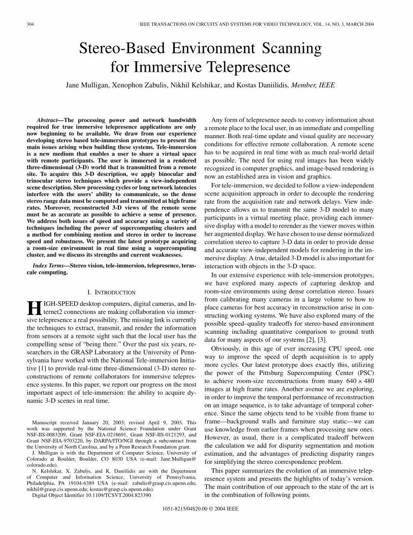
The first working networked tele-immersion prototype (tele-cubicle) that computed 3-D stereo reconstructions, transmittedthem via TCP/IP, and rendered them in a stereoscopic displaywas demonstrated in May of 1999. The rig is illustrated inFig. 1(a) and included a pair of Sony XC77R cameras (center),and a computer monitor (CRT) capable of generating stereoviews for shutter glasses. Computation was provided by a pairof Pentium 450 PCs, one driving the stereoscopic display andthe other capturing image pairs and generating stereo depthmaps. Binocular correlation stereo was used to generate a cloudof depth points, which could optionally be triangulated usingJonathan Shewhuk’s Triangle code [27]. A rotated triangulateddepth view is illustrated in Fig. 1(b).
MULLIGAN et al.: STEREO-BASED ENVIRONMENT SCANNING FOR IMMERSIVE TELEPRESENCE 307
Fig. 1. (a) First networked prototype used shutter glasses and a monitor for stereoscopic viewing. (b) Binocular stereo depth maps were triangulated and rendered.
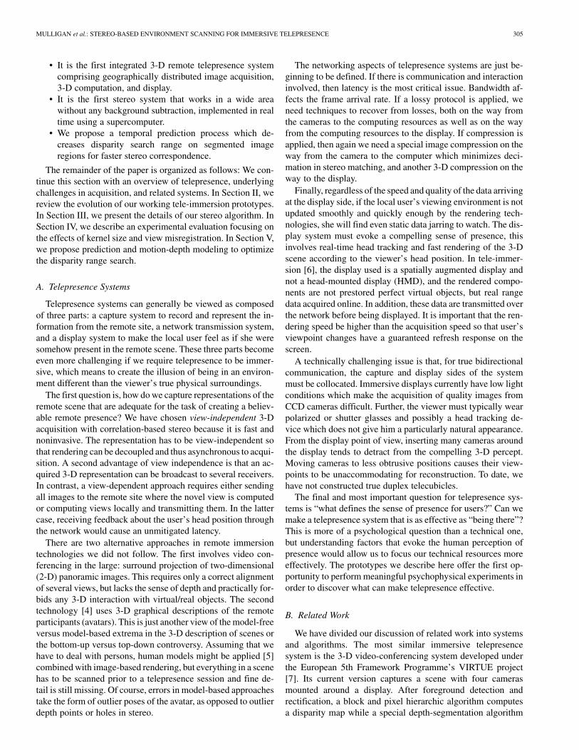
Fig. 2. Traffic peaks into the research triangle on May 2000 demo dates.
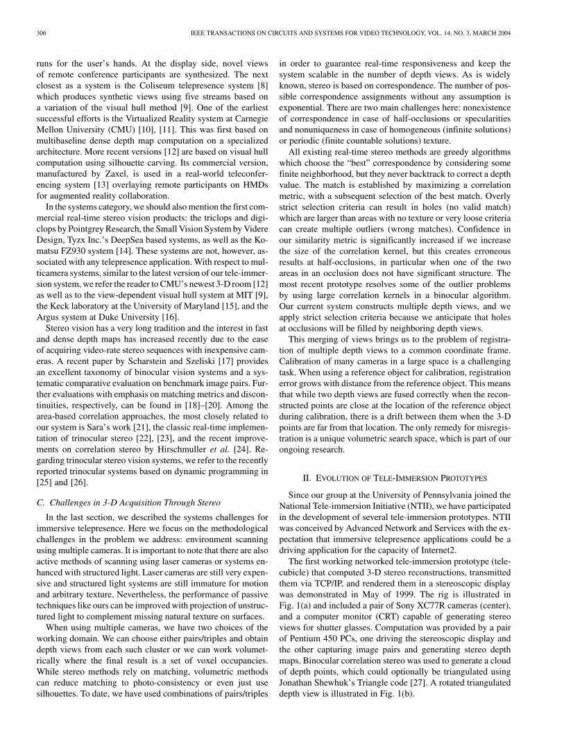
Fig. 3. Working prototypes from May and October 2000. (a) In May, the University of Pennsylvania and advanced network and services each transmitted fivesimultaneous trinocular depth streams to the University of North Carolina Chapel Hill. (b) In October, 3-D interaction and synthetic objects were added to thecollaborative environment.
The next milestone in the tele-immersion project occurredin May 2000 at a major collaborative demonstration amongAdvanced Network and Services in Armonk, New York, theUniversity of North Carolina (UNC), Chapel Hill, and theGRASP Lab at the University of Pennsylvania. The majorinnovations for stereo environment scanning were a changefrom binocular to trinocular correspondence, using a suite ofseven Sony DFW-V500 1394 cameras combined in overlappingtriples, background subtraction and parallelization of the stereoimplementation for quad-processor Dell servers. Naturally, theshear volume of computation and data for transmission wasgreatly increased. We achieved our goal of driving Internet2bandwidth as demonstrated by the plot of traffic into theResearch Triangle on the dates of our demo and rehearsals(see Fig. 2).
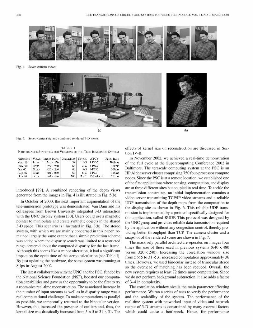
The demo scenario involved transmission of five simulta-neous 3-D views per temporal frame from both Advanced andGRASP. These were combined in the sophisticated immersivedisplay provided by UNC. This included two large displayscreens, one for Armonk and one for Philadelphia, each witha pair of projectors providing differently polarized left–rightstereoscopic views. A High-Ball [28] head tracker providedthe viewer’s head position so 3-D views could be rerenderedcorrectly for the user’s viewpoint. The display is illustratedin Fig. 3(a). The camera rig is illustrated in Fig. 5(a) and anexample temporal frame is in Fig. 4. The cameras were ar-ranged at uniform height in an arc in front of the user. Althoughthe correlation metric remained the same, new methods forrectifying the triple as two independent pairs and combiningthe correlation scores for the current depth estimate were
308 IEEE TRANSACTIONS ON CIRCUITS AND SYSTEMS FOR VIDEO TECHNOLOGY, VOL. 14, NO. 3, MARCH 2004
Fig. 4. Seven camera views.
Fig. 5. Seven-camera rig and combined rendered 3-D views.
TABLE IPERFORMANCE STATISTICS FOR VERSIONS OF THE TELE-IMMERSION SYSTEM
introduced [29]. A combined rendering of the depth viewsgenerated from the images in Fig. 4 is illustrated in Fig. 5(b).
In October of 2000, the next important augmentation of thetele-immersion prototype was demonstrated. Van Dam and hiscolleagues from Brown University integrated 3-D interactionwith the UNC display system [30]. Users could use a magneticpointer to manipulate and create synthetic objects in the shared3-D space. This scenario is illustrated in Fig. 3(b). The stereosystem, with which we are mainly concerned in this paper, re-mained largely the same except that a simple prediction schemewas added where the disparity search was limited to a restrictedrange centered about the computed disparity for the last frame.Although this seems like a minor alteration, it had a significantimpact on the cycle time of the stereo calculation (see Table I).By just updating the hardware, the same system was running at8 fps in August 2002.
The latest collaboration with the UNC and the PSC, funded bythe National Science Foundation (NSF), boosted our computa-tion capabilities and gave us the opportunity to be the first to trya room-size real-time reconstruction. The associated increase inthe number of input streams as well as in disparity range was areal computational challenge. To make computations as parallelas possible, we temporarily returned to the binocular version.However, this increased the presence of outliers and, thus, thekernel size was drastically increased from 5 5 to 31 31. The
effects of kernel size on reconstruction are discussed in Sec-tion IV-B.
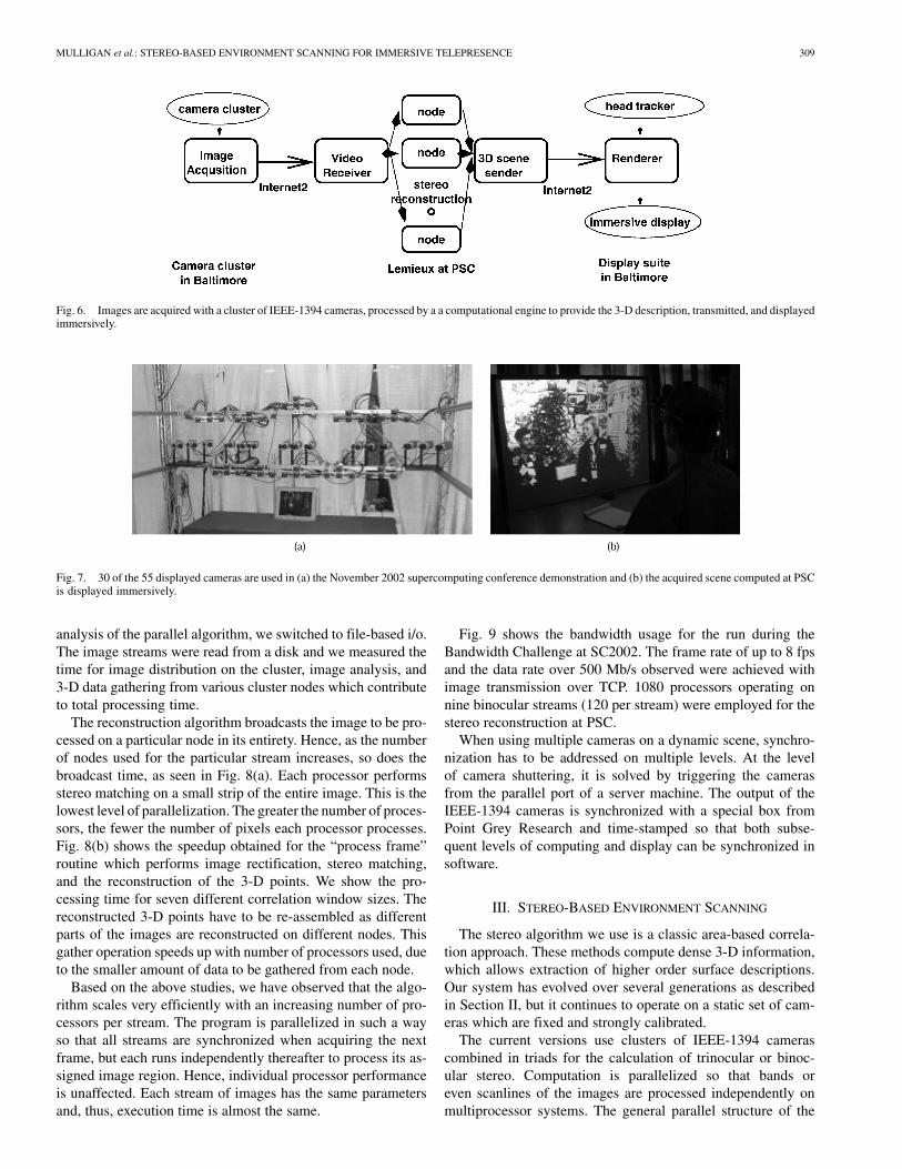
In November 2002, we achieved a real-time demonstrationof the full cycle at the Supercomputing Conference 2002 inBaltimore. The terascale computing system at the PSC is anHP Alphaserver cluster comprising 750 four-processor computenodes. Since the PSC is at a remote location, we established oneof the first applications where sensing, computation, and displayare at three different sites but coupled in real time. To tackle thetransmission constraints, an initial implementation contains avideo server transmitting TCP/IP video streams and a reliableUDP transmission of the depth maps from the computation tothe display site as shown in Fig. 6. This reliable UDP trans-mission is implemented by a protocol specifically designed forthis application, called RUDP. This protocol was designed bythe UNC group and provides reliable data transmission requiredby the application without any congestion control, thereby pro-viding better throughput than TCP. The camera cluster and asnapshot of the rendered scene are shown in Fig. 7.
The massively parallel architecture operates on images fourtimes the size of those used in previous systems (640 480versus 320 240). Increasing the correlation window sizefrom 5 5 to 31 31 increased computation approximately 36times. However, we used binocular instead of trinocular stereoso the overhead of matching has been reduced. Overall, thenew system requires at least 72 times more computation. Sincewe do not perform background subtraction, it also adds a factorof 3–4 in complexity.
The correlation window size is the main parameter affectingperformance. We ran a series of tests to verify the performanceand the scalability of the system. The performance of thereal-time system with networked input of video and networkoutput of 3-D streams is constrained by many external factorswhich could cause a bottleneck. Hence, for performance
MULLIGAN et al.: STEREO-BASED ENVIRONMENT SCANNING FOR IMMERSIVE TELEPRESENCE 309
Fig. 6. Images are acquired with a cluster of IEEE-1394 cameras, processed by a a computational engine to provide the 3-D description, transmitted, and displayedimmersively.
Fig. 7. 30 of the 55 displayed cameras are used in (a) the November 2002 supercomputing conference demonstration and (b) the acquired scene computed at PSCis displayed immersively.
analysis of the parallel algorithm, we switched to file-based i/o.The image streams were read from a disk and we measured thetime for image distribution on the cluster, image analysis, and3-D data gathering from various cluster nodes which contributeto total processing time.
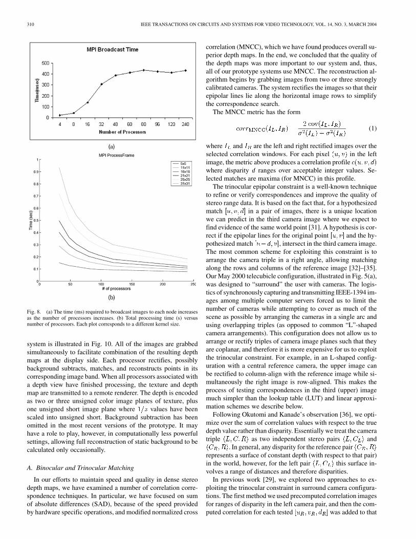
The reconstruction algorithm broadcasts the image to be pro-cessed on a particular node in its entirety. Hence, as the numberof nodes used for the particular stream increases, so does thebroadcast time, as seen in Fig. 8(a). Each processor performsstereo matching on a small strip of the entire image. This is thelowest level of parallelization. The greater the number of proces-sors, the fewer the number of pixels each processor processes.Fig. 8(b) shows the speedup obtained for the “process frame”routine which performs image rectification, stereo matching,and the reconstruction of the 3-D points. We show the pro-cessing time for seven different correlation window sizes. Thereconstructed 3-D points have to be re-assembled as differentparts of the images are reconstructed on different nodes. Thisgather operation speeds up with number of processors used, dueto the smaller amount of data to be gathered from each node.
Based on the above studies, we have observed that the algo-rithm scales very efficiently with an increasing number of pro-cessors per stream. The program is parallelized in such a wayso that all streams are synchronized when acquiring the nextframe, but each runs independently thereafter to process its as-signed image region. Hence, individual processor performanceis unaffected. Each stream of images has the same parametersand, thus, execution time is almost the same.
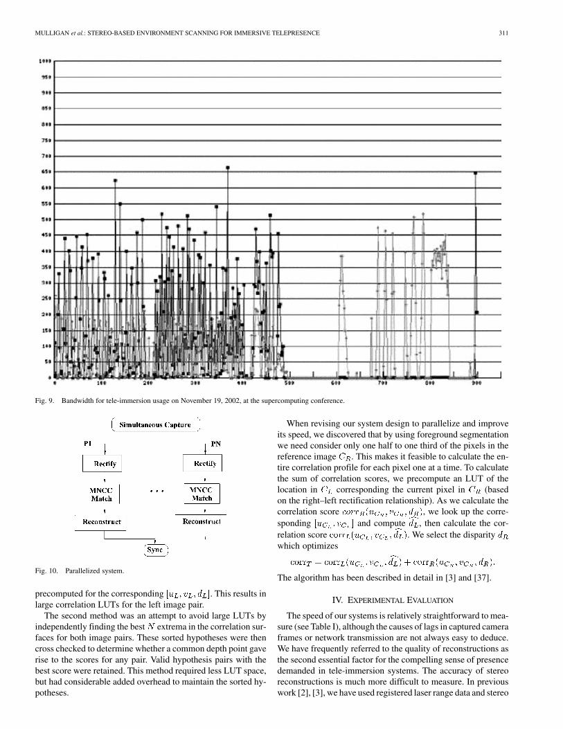
Fig. 9 shows the bandwidth usage for the run during theBandwidth Challenge at SC2002. The frame rate of up to 8 fpsand the data rate over 500 Mb/s observed were achieved withimage transmission over TCP. 1080 processors operating onnine binocular streams (120 per stream) were employed for thestereo reconstruction at PSC.
When using multiple cameras on a dynamic scene, synchro-nization has to be addressed on multiple levels. At the levelof camera shuttering, it is solved by triggering the camerasfrom the parallel port of a server machine. The output of theIEEE-1394 cameras is synchronized with a special box fromPoint Grey Research and time-stamped so that both subse-quent levels of computing and display can be synchronized insoftware.
III. STEREO-BASED ENVIRONMENT SCANNING
The stereo algorithm we use is a classic area-based correla-tion approach. These methods compute dense 3-D information,which allows extraction of higher order surface descriptions.Our system has evolved over several generations as describedin Section II, but it continues to operate on a static set of cam-eras which are fixed and strongly calibrated.
The current versions use clusters of IEEE-1394 camerascombined in triads for the calculation of trinocular or binoc-ular stereo. Computation is parallelized so that bands oreven scanlines of the images are processed independently onmultiprocessor systems. The general parallel structure of the
310 IEEE TRANSACTIONS ON CIRCUITS AND SYSTEMS FOR VIDEO TECHNOLOGY, VOL. 14, NO. 3, MARCH 2004
Fig. 8. (a) The time (ms) required to broadcast images to each node increasesas the number of processors increases. (b) Total processing time (s) versusnumber of processors. Each plot corresponds to a different kernel size.
system is illustrated in Fig. 10. All of the images are grabbedsimultaneously to facilitate combination of the resulting depthmaps at the display side. Each processor rectifies, possiblybackground subtracts, matches, and reconstructs points in itscorresponding image band. When all processors associated witha depth view have finished processing, the texture and depthmap are transmitted to a remote renderer. The depth is encodedas two or three unsigned color image planes of texture, plusone unsigned short image plane where values have beenscaled into unsigned short. Background subtraction has beenomitted in the most recent versions of the prototype. It mayhave a role to play, however, in computationally less powerfulsettings, allowing full reconstruction of static background to becalculated only occasionally.
A. Binocular and Trinocular Matching
In our efforts to maintain speed and quality in dense stereodepth maps, we have examined a number of correlation corre-spondence techniques. In particular, we have focused on sumof absolute differences (SAD), because of the speed providedby hardware specific operations, and modified normalized cross
correlation (MNCC), which we have found produces overall su-perior depth maps. In the end, we concluded that the quality ofthe depth maps was more important to our system and, thus,all of our prototype systems use MNCC. The reconstruction al-gorithm begins by grabbing images from two or three stronglycalibrated cameras. The system rectifies the images so that theirepipolar lines lie along the horizontal image rows to simplifythe correspondence search.
The MNCC metric has the form
(1)
where and are the left and right rectified images over theselected correlation windows. For each pixel in the leftimage, the metric above produces a correlation profilewhere disparity ranges over acceptable integer values. Se-lected matches are maxima (for MNCC) in this profile.
The trinocular epipolar constraint is a well-known techniqueto refine or verify correspondences and improve the quality ofstereo range data. It is based on the fact that, for a hypothesizedmatch in a pair of images, there is a unique locationwe can predict in the third camera image where we expect tofind evidence of the same world point [31]. A hypothesis is cor-rect if the epipolar lines for the original point and the hy-pothesized match , intersect in the third camera image.The most common scheme for exploiting this constraint is toarrange the camera triple in a right angle, allowing matchingalong the rows and columns of the reference image [32]–[35].Our May 2000 telecubicle configuration, illustrated in Fig. 5(a),was designed to “surround” the user with cameras. The logis-tics of synchronously capturing and transmitting IEEE-1394 im-ages among multiple computer servers forced us to limit thenumber of cameras while attempting to cover as much of thescene as possible by arranging the cameras in a single arc andusing overlapping triples (as opposed to common “L”-shapedcamera arrangements). This configuration does not allow us toarrange or rectify triples of camera image planes such that theyare coplanar, and therefore it is more expensive for us to exploitthe trinocular constraint. For example, in an L-shaped config-uration with a central reference camera, the upper image canbe rectified to column-align with the reference image while si-multaneously the right image is row-aligned. This makes theprocess of testing correspondences in the third (upper) imagemuch simpler than the lookup table (LUT) and linear approxi-mation schemes we describe below.
Following Okutomi and Kanade’s observation [36], we opti-mize over the sum of correlation values with respect to the truedepth value rather than disparity. Essentially we treat the cameratriple as two independent stereo pairs and
. In general, any disparity for the reference pairrepresents a surface of constant depth (with respect to that pair)in the world, however, for the left pair this surface in-volves a range of distances and therefore disparities.
In previous work [29], we explored two approaches to ex-ploiting the trinocular constraint in surround camera configura-tions. The first method we used precomputed correlation imagesfor ranges of disparity in the left camera pair, and then the com-puted correlation for each tested was added to that
MULLIGAN et al.: STEREO-BASED ENVIRONMENT SCANNING FOR IMMERSIVE TELEPRESENCE 311
Fig. 9. Bandwidth for tele-immersion usage on November 19, 2002, at the supercomputing conference.
Fig. 10. Parallelized system.
precomputed for the corresponding . This results inlarge correlation LUTs for the left image pair.
The second method was an attempt to avoid large LUTs byindependently finding the best extrema in the correlation sur-faces for both image pairs. These sorted hypotheses were thencross checked to determine whether a common depth point gaverise to the scores for any pair. Valid hypothesis pairs with thebest score were retained. This method required less LUT space,but had considerable added overhead to maintain the sorted hy-potheses.
When revising our system design to parallelize and improveits speed, we discovered that by using foreground segmentationwe need consider only one half to one third of the pixels in thereference image . This makes it feasible to calculate the en-tire correlation profile for each pixel one at a time. To calculatethe sum of correlation scores, we precompute an LUT of thelocation in corresponding the current pixel in (basedon the right–left rectification relationship). As we calculate thecorrelation score , we look up the corre-sponding and compute , then calculate the cor-relation score . We select the disparitywhich optimizes
The algorithm has been described in detail in [3] and [37].
IV. EXPERIMENTAL EVALUATION
The speed of our systems is relatively straightforward to mea-sure (see Table I), although the causes of lags in captured cameraframes or network transmission are not always easy to deduce.We have frequently referred to the quality of reconstructions asthe second essential factor for the compelling sense of presencedemanded in tele-immersion systems. The accuracy of stereoreconstructions is much more difficult to measure. In previouswork [2], [3], we have used registered laser range data and stereo

312 IEEE TRANSACTIONS ON CIRCUITS AND SYSTEMS FOR VIDEO TECHNOLOGY, VOL. 14, NO. 3, MARCH 2004
Fig. 11. (a)–(c) Trinocular image data registered to (b) laser data.
Fig. 12. Smoothing of the NN error histogram with increasing mask size (N � N ).
reconstructions of the same object (Fig. 11) to evaluate the ac-curacy of our systems.
The two most significant concerns regarding the quality ofoutput of the wide-area stereo algorithm are identified to be theaccuracy of disparity computation at depth discontinuities, andthe registration errors observed when merging reconstructionresults from multiple stereo pairs or triplets.
A. Global Effects of Kernel Size
Most recently we have examined the consequences of thelarge mask sizes used in the current prototype on the accuracyof our reconstructions. Using our registered dataset, a nearestneighbor (NN) error metric (each reconstructed point is as-signed an error equal to the distance to the nearest registeredlaser data point) was computed for reconstructions using masksizes of 5 5, 7 7, 16 16, 32 32 and 64 64. Fig. 12illustrates the diffusing effect of increasing mask dimensionon the error histogram. We can see the effect of large masks onthe reconstructed data in Fig. 13. The disparity map is muchsmoother for , and outliers are significantly reduced,but there is also a change in shape from Fig. 13(c) to (d). Wecan also observe the flattened halo (boundary overreach) atthe boundary of Fig. 13(b), caused by smoothing across theocclusion boundary.
When selecting kernel size, we have observed that we obtaina more pleasing result for large-size kernels than smaller ones.That is, end users are less disturbed by a result that includesminor distortion and artifacts at occlusion boundaries than a re-sult that includes holes and outliers. A reason for this is that out-liers look like dust or confetti floating in the scene and preventan observer from clearly perceiving the form of reconstructedobjects.
Fig. 13. Disparity maps and rotated reconstructions forN = 7 andN = 32.
B. Effects of Kernel Size on Discontinuities
Inaccuracies in the disparity map computed by the algorithmare mainly observed at image regions corresponding to depth
MULLIGAN et al.: STEREO-BASED ENVIRONMENT SCANNING FOR IMMERSIVE TELEPRESENCE 313
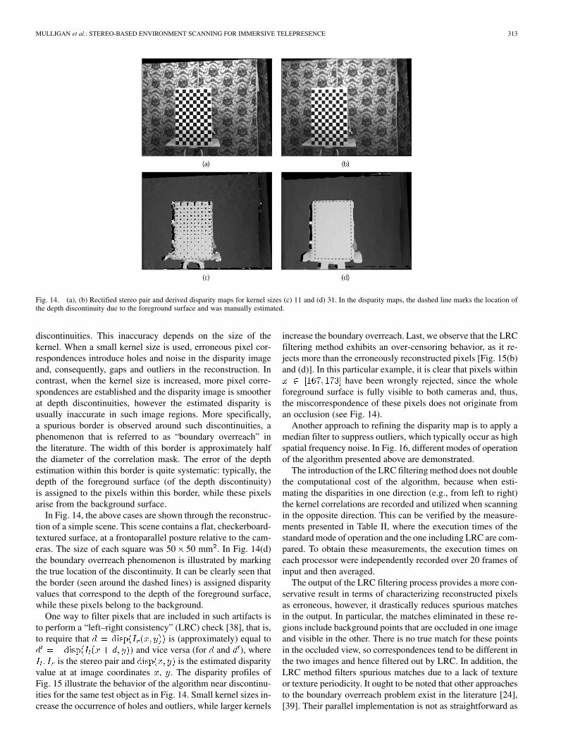
Fig. 14. (a), (b) Rectified stereo pair and derived disparity maps for kernel sizes (c) 11 and (d) 31. In the disparity maps, the dashed line marks the location ofthe depth discontinuity due to the foreground surface and was manually estimated.
discontinuities. This inaccuracy depends on the size of thekernel. When a small kernel size is used, erroneous pixel cor-respondences introduce holes and noise in the disparity imageand, consequently, gaps and outliers in the reconstruction. Incontrast, when the kernel size is increased, more pixel corre-spondences are established and the disparity image is smootherat depth discontinuities, however the estimated disparity isusually inaccurate in such image regions. More specifically,a spurious border is observed around such discontinuities, aphenomenon that is referred to as “boundary overreach” inthe literature. The width of this border is approximately halfthe diameter of the correlation mask. The error of the depthestimation within this border is quite systematic: typically, thedepth of the foreground surface (of the depth discontinuity)is assigned to the pixels within this border, while these pixelsarise from the background surface.
In Fig. 14, the above cases are shown through the reconstruc-tion of a simple scene. This scene contains a flat, checkerboard-textured surface, at a frontoparallel posture relative to the cam-eras. The size of each square was 50 50 mm . In Fig. 14(d)the boundary overreach phenomenon is illustrated by markingthe true location of the discontinuity. It can be clearly seen thatthe border (seen around the dashed lines) is assigned disparityvalues that correspond to the depth of the foreground surface,while these pixels belong to the background.
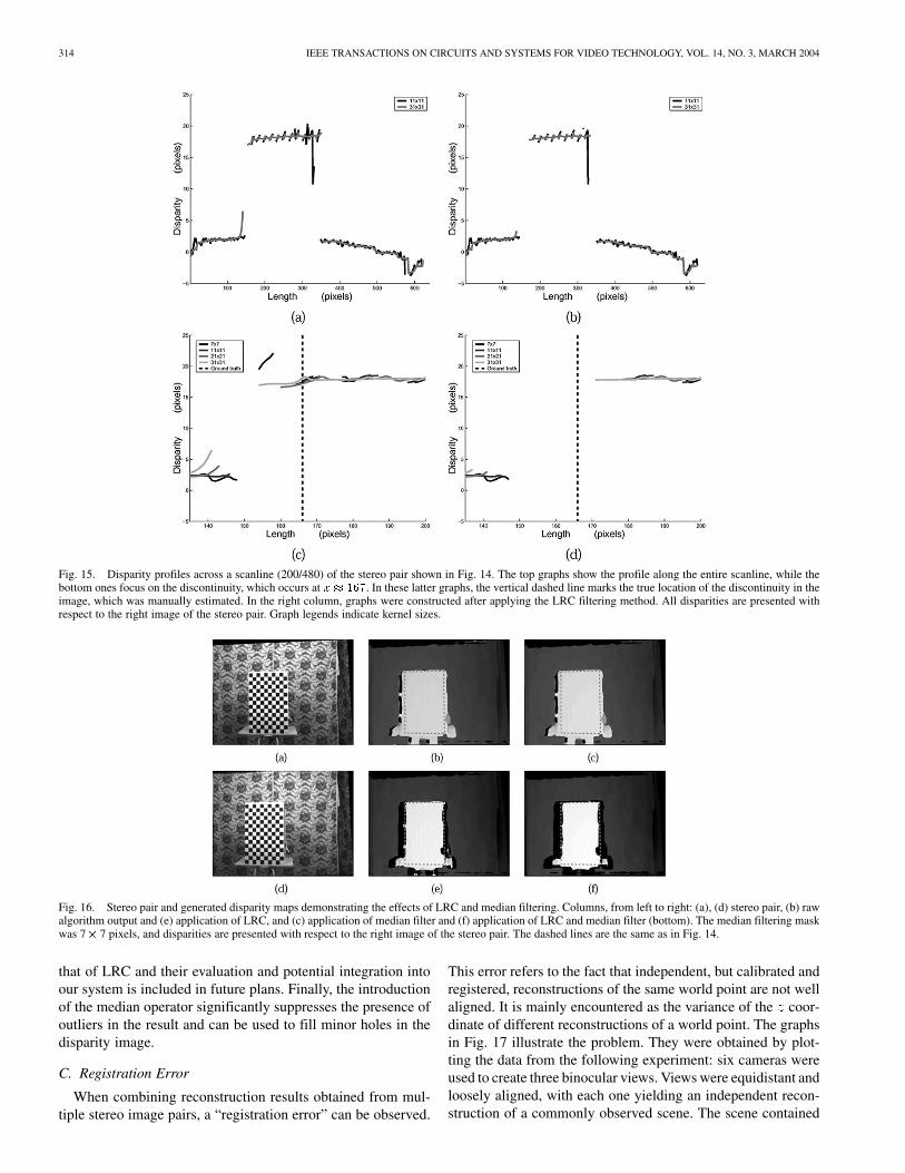
One way to filter pixels that are included in such artifacts isto perform a “left–right consistency” (LRC) check [38], that is,to require that is (approximately) equal to
and vice versa (for and ), whereis the stereo pair and is the estimated disparity
value at at image coordinates , . The disparity profiles ofFig. 15 illustrate the behavior of the algorithm near discontinu-ities for the same test object as in Fig. 14. Small kernel sizes in-crease the occurrence of holes and outliers, while larger kernels
increase the boundary overreach. Last, we observe that the LRCfiltering method exhibits an over-censoring behavior, as it re-jects more than the erroneously reconstructed pixels [Fig. 15(b)and (d)]. In this particular example, it is clear that pixels within
have been wrongly rejected, since the wholeforeground surface is fully visible to both cameras and, thus,the miscorrespondence of these pixels does not originate froman occlusion (see Fig. 14).
Another approach to refining the disparity map is to apply amedian filter to suppress outliers, which typically occur as highspatial frequency noise. In Fig. 16, different modes of operationof the algorithm presented above are demonstrated.
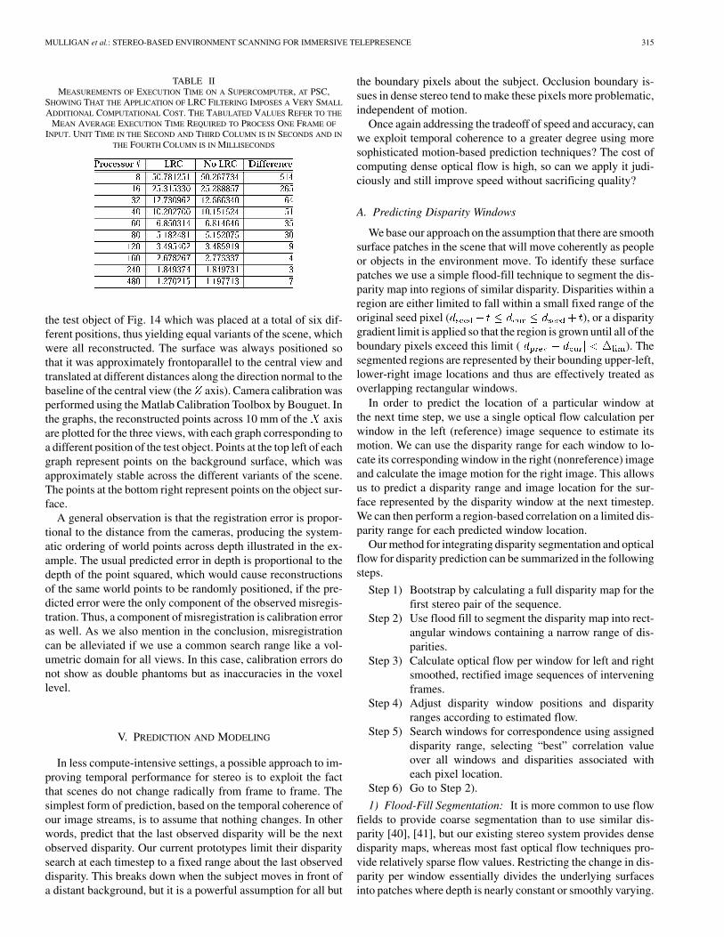
The introduction of the LRC filtering method does not doublethe computational cost of the algorithm, because when esti-mating the disparities in one direction (e.g., from left to right)the kernel correlations are recorded and utilized when scanningin the opposite direction. This can be verified by the measure-ments presented in Table II, where the execution times of thestandard mode of operation and the one including LRC are com-pared. To obtain these measurements, the execution times oneach processor were independently recorded over 20 frames ofinput and then averaged.
The output of the LRC filtering process provides a more con-servative result in terms of characterizing reconstructed pixelsas erroneous, however, it drastically reduces spurious matchesin the output. In particular, the matches eliminated in these re-gions include background points that are occluded in one imageand visible in the other. There is no true match for these pointsin the occluded view, so correspondences tend to be different inthe two images and hence filtered out by LRC. In addition, theLRC method filters spurious matches due to a lack of textureor texture periodicity. It ought to be noted that other approachesto the boundary overreach problem exist in the literature [24],[39]. Their parallel implementation is not as straightforward as
314 IEEE TRANSACTIONS ON CIRCUITS AND SYSTEMS FOR VIDEO TECHNOLOGY, VOL. 14, NO. 3, MARCH 2004
Fig. 15. Disparity profiles across a scanline (200/480) of the stereo pair shown in Fig. 14. The top graphs show the profile along the entire scanline, while thebottom ones focus on the discontinuity, which occurs at x � 167. In these latter graphs, the vertical dashed line marks the true location of the discontinuity in theimage, which was manually estimated. In the right column, graphs were constructed after applying the LRC filtering method. All disparities are presented withrespect to the right image of the stereo pair. Graph legends indicate kernel sizes.
Fig. 16. Stereo pair and generated disparity maps demonstrating the effects of LRC and median filtering. Columns, from left to right: (a), (d) stereo pair, (b) rawalgorithm output and (e) application of LRC, and (c) application of median filter and (f) application of LRC and median filter (bottom). The median filtering maskwas 7� 7 pixels, and disparities are presented with respect to the right image of the stereo pair. The dashed lines are the same as in Fig. 14.
that of LRC and their evaluation and potential integration intoour system is included in future plans. Finally, the introductionof the median operator significantly suppresses the presence ofoutliers in the result and can be used to fill minor holes in thedisparity image.
C. Registration Error
When combining reconstruction results obtained from mul-tiple stereo image pairs, a “registration error” can be observed.
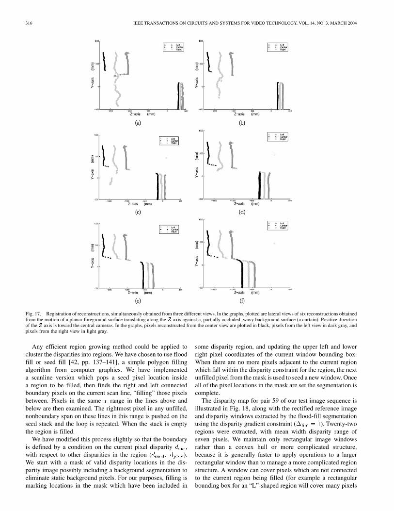
This error refers to the fact that independent, but calibrated andregistered, reconstructions of the same world point are not wellaligned. It is mainly encountered as the variance of the coor-dinate of different reconstructions of a world point. The graphsin Fig. 17 illustrate the problem. They were obtained by plot-ting the data from the following experiment: six cameras wereused to create three binocular views. Views were equidistant andloosely aligned, with each one yielding an independent recon-struction of a commonly observed scene. The scene contained
MULLIGAN et al.: STEREO-BASED ENVIRONMENT SCANNING FOR IMMERSIVE TELEPRESENCE 315
TABLE IIMEASUREMENTS OF EXECUTION TIME ON A SUPERCOMPUTER, AT PSC,
SHOWING THAT THE APPLICATION OF LRC FILTERING IMPOSES A VERY SMALL
ADDITIONAL COMPUTATIONAL COST. THE TABULATED VALUES REFER TO THE
MEAN AVERAGE EXECUTION TIME REQUIRED TO PROCESS ONE FRAME OF
INPUT. UNIT TIME IN THE SECOND AND THIRD COLUMN IS IN SECONDS AND IN
THE FOURTH COLUMN IS IN MILLISECONDS
the test object of Fig. 14 which was placed at a total of six dif-ferent positions, thus yielding equal variants of the scene, whichwere all reconstructed. The surface was always positioned sothat it was approximately frontoparallel to the central view andtranslated at different distances along the direction normal to thebaseline of the central view (the axis). Camera calibration wasperformed using the Matlab Calibration Toolbox by Bouguet. Inthe graphs, the reconstructed points across 10 mm of the axisare plotted for the three views, with each graph corresponding toa different position of the test object. Points at the top left of eachgraph represent points on the background surface, which wasapproximately stable across the different variants of the scene.The points at the bottom right represent points on the object sur-face.
A general observation is that the registration error is propor-tional to the distance from the cameras, producing the system-atic ordering of world points across depth illustrated in the ex-ample. The usual predicted error in depth is proportional to thedepth of the point squared, which would cause reconstructionsof the same world points to be randomly positioned, if the pre-dicted error were the only component of the observed misregis-tration. Thus, a component of misregistration is calibration erroras well. As we also mention in the conclusion, misregistrationcan be alleviated if we use a common search range like a vol-umetric domain for all views. In this case, calibration errors donot show as double phantoms but as inaccuracies in the voxellevel.
V. PREDICTION AND MODELING
In less compute-intensive settings, a possible approach to im-proving temporal performance for stereo is to exploit the factthat scenes do not change radically from frame to frame. Thesimplest form of prediction, based on the temporal coherence ofour image streams, is to assume that nothing changes. In otherwords, predict that the last observed disparity will be the nextobserved disparity. Our current prototypes limit their disparitysearch at each timestep to a fixed range about the last observeddisparity. This breaks down when the subject moves in front ofa distant background, but it is a powerful assumption for all but
the boundary pixels about the subject. Occlusion boundary is-sues in dense stereo tend to make these pixels more problematic,independent of motion.
Once again addressing the tradeoff of speed and accuracy, canwe exploit temporal coherence to a greater degree using moresophisticated motion-based prediction techniques? The cost ofcomputing dense optical flow is high, so can we apply it judi-ciously and still improve speed without sacrificing quality?
A. Predicting Disparity Windows
We base our approach on the assumption that there are smoothsurface patches in the scene that will move coherently as peopleor objects in the environment move. To identify these surfacepatches we use a simple flood-fill technique to segment the dis-parity map into regions of similar disparity. Disparities within aregion are either limited to fall within a small fixed range of theoriginal seed pixel ( ), or a disparitygradient limit is applied so that the region is grown until all of theboundary pixels exceed this limit ( ). Thesegmented regions are represented by their bounding upper-left,lower-right image locations and thus are effectively treated asoverlapping rectangular windows.
In order to predict the location of a particular window atthe next time step, we use a single optical flow calculation perwindow in the left (reference) image sequence to estimate itsmotion. We can use the disparity range for each window to lo-cate its corresponding window in the right (nonreference) imageand calculate the image motion for the right image. This allowsus to predict a disparity range and image location for the sur-face represented by the disparity window at the next timestep.We can then perform a region-based correlation on a limited dis-parity range for each predicted window location.
Our method for integrating disparity segmentation and opticalflow for disparity prediction can be summarized in the followingsteps.
Step 1) Bootstrap by calculating a full disparity map for thefirst stereo pair of the sequence.
Step 2) Use flood fill to segment the disparity map into rect-angular windows containing a narrow range of dis-parities.
Step 3) Calculate optical flow per window for left and rightsmoothed, rectified image sequences of interveningframes.
Step 4) Adjust disparity window positions and disparityranges according to estimated flow.
Step 5) Search windows for correspondence using assigneddisparity range, selecting “best” correlation valueover all windows and disparities associated witheach pixel location.
Step 6) Go to Step 2).
1) Flood-Fill Segmentation: It is more common to use flowfields to provide coarse segmentation than to use similar dis-parity [40], [41], but our existing stereo system provides densedisparity maps, whereas most fast optical flow techniques pro-vide relatively sparse flow values. Restricting the change in dis-parity per window essentially divides the underlying surfacesinto patches where depth is nearly constant or smoothly varying.
316 IEEE TRANSACTIONS ON CIRCUITS AND SYSTEMS FOR VIDEO TECHNOLOGY, VOL. 14, NO. 3, MARCH 2004
Fig. 17. Registration of reconstructions, simultaneously obtained from three different views. In the graphs, plotted are lateral views of six reconstructions obtainedfrom the motion of a planar foreground surface translating along the Z axis against a, partially occluded, wavy background surface (a curtain). Positive directionof the Z axis is toward the central cameras. In the graphs, pixels reconstructed from the center view are plotted in black, pixels from the left view in dark gray, andpixels from the right view in light gray.
Any efficient region growing method could be applied tocluster the disparities into regions. We have chosen to use floodfill or seed fill [42, pp. 137–141], a simple polygon fillingalgorithm from computer graphics. We have implementeda scanline version which pops a seed pixel location insidea region to be filled, then finds the right and left connectedboundary pixels on the current scan line, “filling” those pixelsbetween. Pixels in the same range in the lines above andbelow are then examined. The rightmost pixel in any unfilled,nonboundary span on these lines in this range is pushed on theseed stack and the loop is repeated. When the stack is emptythe region is filled.
We have modified this process slightly so that the boundaryis defined by a condition on the current pixel disparity ,with respect to other disparities in the region ( ).We start with a mask of valid disparity locations in the dis-parity image possibly including a background segmentation toeliminate static background pixels. For our purposes, filling ismarking locations in the mask which have been included in
some disparity region, and updating the upper left and lowerright pixel coordinates of the current window bounding box.When there are no more pixels adjacent to the current regionwhich fall within the disparity constraint for the region, the nextunfilled pixel from the mask is used to seed a new window. Onceall of the pixel locations in the mask are set the segmentation iscomplete.
The disparity map for pair 59 of our test image sequence isillustrated in Fig. 18, along with the rectified reference imageand disparity windows extracted by the flood-fill segmentationusing the disparity gradient constraint ( ). Twenty-tworegions were extracted, with mean width disparity range ofseven pixels. We maintain only rectangular image windowsrather than a convex hull or more complicated structure,because it is generally faster to apply operations to a largerrectangular window than to manage a more complicated regionstructure. A window can cover pixels which are not connectedto the current region being filled (for example a rectangularbounding box for an “L”-shaped region will cover many pixels
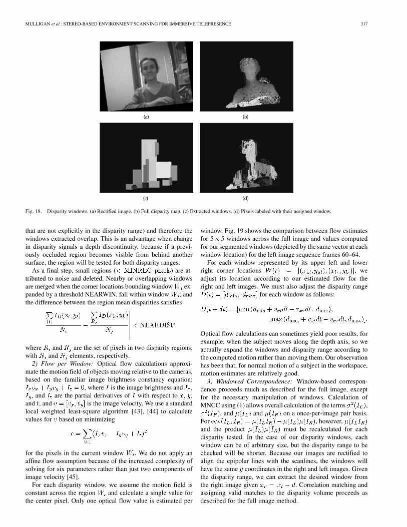
MULLIGAN et al.: STEREO-BASED ENVIRONMENT SCANNING FOR IMMERSIVE TELEPRESENCE 317
Fig. 18. Disparity windows. (a) Rectified image. (b) Full disparity map. (c) Extracted windows. (d) Pixels labeled with their assigned window.
that are not explicitly in the disparity range) and therefore thewindows extracted overlap. This is an advantage when changein disparity signals a depth discontinuity, because if a previ-ously occluded region becomes visible from behind anothersurface, the region will be tested for both disparity ranges.
As a final step, small regions ( ) are at-tributed to noise and deleted. Nearby or overlapping windowsare merged when the corner locations bounding window ex-panded by a threshold NEARWIN, fall within window , andthe difference between the region mean disparities satisfies
where and are the set of pixels in two disparity regions,with and elements, respectively.
2) Flow per Window: Optical flow calculations approxi-mate the motion field of objects moving relative to the cameras,based on the familiar image brightness constancy equation:
, where is the image brightness and ,, and are the partial derivatives of with respect to , ,
and , and is the image velocity. We use a standardlocal weighted least-square algorithm [43], [44] to calculatevalues for based on minimizing
for the pixels in the current window . We do not apply anaffine flow assumption because of the increased complexity ofsolving for six parameters rather than just two components ofimage velocity [45].
For each disparity window, we assume the motion field isconstant across the region and calculate a single value forthe center pixel. Only one optical flow value is estimated per
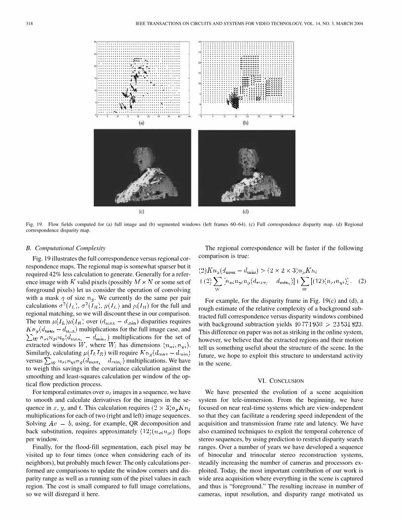
window. Fig. 19 shows the comparison between flow estimatesfor 5 5 windows across the full image and values computedfor our segmented windows (depicted by the same vector at eachwindow location) for the left image sequence frames 60–64.
For each window represented by its upper left and lowerright corner locations , weadjust its location according to our estimated flow for theright and left images. We must also adjust the disparity range
for each window as follows:
Optical flow calculations can sometimes yield poor results, forexample, when the subject moves along the depth axis, so weactually expand the windows and disparity range according tothe computed motion rather than moving them. Our observationhas been that, for normal motion of a subject in the workspace,motion estimates are relatively good.
3) Windowed Correspondence: Window-based correspon-dence proceeds much as described for the full image, exceptfor the necessary manipulation of windows. Calculation ofMNCC using (1) allows overall calculation of the terms ,
, and and on a once-per-image pair basis.For , however,and the product must be recalculated for eachdisparity tested. In the case of our disparity windows, eachwindow can be of arbitrary size, but the disparity range to bechecked will be shorter. Because our images are rectified toalign the epipolar lines with the scanlines, the windows willhave the same coordinates in the right and left images. Giventhe disparity range, we can extract the desired window fromthe right image given . Correlation matching andassigning valid matches to the disparity volume proceeds asdescribed for the full image method.
318 IEEE TRANSACTIONS ON CIRCUITS AND SYSTEMS FOR VIDEO TECHNOLOGY, VOL. 14, NO. 3, MARCH 2004
Fig. 19. Flow fields computed for (a) full image and (b) segmented windows (left frames 60–64). (c) Full correspondence disparity map. (d) Regionalcorrespondence disparity map.
B. Computational Complexity
Fig. 19 illustrates the full correspondence versus regional cor-respondence maps. The regional map is somewhat sparser but itrequired 42% less calculation to generate. Generally for a refer-ence image with valid pixels (possibly or some set offoreground pixels) let us consider the operation of convolvingwith a mask of size . We currently do the same per paircalculations , , and for the full andregional matching, so we will discount these in our comparison.The term over ( ) disparities requires
multiplications for the full image case, andmultiplications for the set of
extracted windows , where has dimensions .Similarly, calculating will requireversus multiplications. We haveto weigh this savings in the covariance calculation against thesmoothing and least-squares calculation per window of the op-tical flow prediction process.
For temporal estimates over images in a sequence, we haveto smooth and calculate derivatives for the images in the se-quence in , , and . This calculation requiresmultiplications for each of two (right and left) image sequences.Solving , using, for example, QR decomposition andback substitution, requires approximately flopsper window.
Finally, for the flood-fill segmentation, each pixel may bevisited up to four times (once when considering each of itsneighbors), but probably much fewer. The only calculations per-formed are comparisons to update the window corners and dis-parity range as well as a running sum of the pixel values in eachregion. The cost is small compared to full image correlations,so we will disregard it here.
The regional correspondence will be faster if the followingcomparison is true:
(2)
For example, for the disparity frame in Fig. 19(c) and (d), arough estimate of the relative complexity of a background sub-tracted full correspondence versus disparity windows combinedwith background subtraction yields .This difference on paper was not as striking in the online system,however, we believe that the extracted regions and their motiontell us something useful about the structure of the scene. In thefuture, we hope to exploit this structure to understand activityin the scene.
VI. CONCLUSION
We have presented the evolution of a scene acquisitionsystem for tele-immersion. From the beginning, we havefocused on near real-time systems which are view-independentso that they can facilitate a rendering speed independent of theacquisition and transmission frame rate and latency. We havealso examined techniques to exploit the temporal coherence ofstereo sequences, by using prediction to restrict disparity searchranges. Over a number of years we have developed a sequenceof binocular and trinocular stereo reconstruction systems,steadily increasing the number of cameras and processors ex-ploited. Today, the most important contribution of our work iswide area acquisition where everything in the scene is capturedand thus is “foreground.” The resulting increase in number ofcameras, input resolution, and disparity range motivated us
MULLIGAN et al.: STEREO-BASED ENVIRONMENT SCANNING FOR IMMERSIVE TELEPRESENCE 319
to use massive parallelization and produce a truly distributedsensing-computing-display system for tele-immersion.
In the immediate future, we are addressing the problems ofocclusion and misregistration. In a wide surround distributionof cameras, there is no clear definition of occlusion like thedefinition of half-occlusion in stereo. Views producing outliersor holes at half-occlusions should be corrected by other views.Such a fusion process necessitates a good confidence metric. Toavoid fusion, we will pursue a volumetric approach (see [46]for thorough treatment) where we deal with a unique disparityspace for all cameras, but then visibility becomes a problem:which views should be used for photoconsistency or to com-pute correlation? Parallelization of a volumetric approach be-comes a challenging problem with many more interconnectionsbetween mutually independent input streams. A volumetric ap-proach would also treat symmetrically the problem of misregis-tration due to calibration errors by blurring the estimated voxelsinstead of duplicating depth maps. However, wide-area calibra-tion remains a challenge.
Collocating large immersive displays with cameras for en-vironment scanning in order to provide duplex communicationpresents further technological challenges. It requires addressingthe problem of rendering the scene from viewpoints far fromthe viewpoints where the input streams were captured for re-construction. In a collocated display-camera system, it is nat-ural to ask for localization of face and body parts so that headtracking as well as gesture recognition will be accomplishedwithout wearing devices. Full duplex communication will alsoenable the start of human performance experiments where wewill be able to study the question of whether specific collabora-tion tasks can be better addressed with tele-immersion than withplain or even large-scale videoconferencing.
ACKNOWLEDGMENT
The authors would like to thank J. Lanier, H. Fuchs, andA. van Dam for the wonderful collaboration in the NationalTele-immersion Initiative as well as H. Towles and the entireUNC team for their contribution to the November 2002 demon-stration. They also thank R. Sara and G. Kamberova for the ini-tial offline implementation of tele-immersion at the Universityof Pennsylvania.
REFERENCES
[1] J. Lanier, “Virtually there,” Scientific Amer., pp. 66–75, Apr. 2001.[2] J. Mulligan, V. Isler, and K. Daniilidis, “Performance evaluation of
stereo for tele-presence,” in Proc. 8th IEEE Int. Conf. Computer Vision(ICCV’01), vol. 2, Vancouver, BC, Canada, July 2001, pp. 558–565.
[3] , “Trinocular stereo: A real-time algorithm and its evaluation,” Int.J. Comput. Vis., vol. 47, no. 1/2/3, pp. 51–61, 2002.
[4] J. Leigh, A. Johnson, M. Brown, D. Sandin, and T. DeFanti, “Visual-ization in teleimmersive environments,” Computer, vol. 32, no. 12, pp.66–73, 1999.
[5] A. Hilton, D. Beresford, T. Gentils, R. Smith, W. Sun, and J. Illingworth,“Whole-body modeling of people from multi-view images to populatevirtual worlds,” Int. J. Comput Graphics, vol. 16, no. 7, pp. 411–436,2000.
[6] R. Raskar, G. Welch, M. Cutts, A. Lake, L. Stesin, and H. Fuchs, “Theoffice of the future: A unified approach to image-based modeling andspatially immersive displays,” in Proc. ACM SIGGRAPH, 1998, pp.179–188.
[7] P. Kauff and O. Schreer, “An immersive 3-D video-conferencing systemusing shared virtual team user environments,” in Proc. ACM Conf. Col-laborative Virtual Environments, 2002.
[8] H. Baker, D. Tanguay, I. Sobel, D. Gelb, M. Gross, W. Culbertson, andT. Malzbender, “The coliseum immersive teleconferencing system,” inProc. Int. Workshop Immersive Telepresence, Juan-les-Pins, France,Dec. 6, 2002.
[9] W. Matusik, C. Buheler, R. Raskar, S. Gortler, and L. McMillan, “Image-based visual hulls,” in Proc. ACM SIGGRAPH, 2000, pp. 369–374.
[10] T. Kanade, A. Yoshida, K. Oda, H. Kano, and M. Tanaka, “A stereo en-gine for video-rate dense depth mapping and its new applications,” inProc. IEEE Conf. Computer Vision and Pattern Recognition, San Fran-sisco, CA, June 18–20, 1996, pp. 196–202.
[11] P. Narayanan, P. Rander, and T. Kanade, “Constructing virtual worldsusing dense stereo,” in Proc. Int. Conf. Computer Vision, 1998, pp. 3–10.
[12] G. Cheung, T. Kanade, J. Bouguet, and M. Holler, “A real time systemfor robust 3-D voxel reconstruction of human motions,” in Proc. IEEEConf. Computer Vision and Pattern Recognition, Hilton Head Island,SC, June 13–15, 2000, pp. 714–720.
[13] M. Billinghurst, A. Cheok, S. Prince, and H. Kato, “Projects in vr: Realworld teleconferencing,” IEEE Comput. Graph. Applicat., vol. 22, pp.11–13, 2002.
[14] T. Naemura, J. Tago, and H. Harashima, “Real-time video based mod-eling and rendering of 3d scenes,” IEEE Computer Graph. Applicat.,vol. 22, pp. 66–73, 2002.
[15] P. Baker and Y. Aloimonos, “Complete calibration of a multi-cameranetwork,” in Proc. IEEE Workshop Omnidirectional Vision, Hilton HeadIsland, SC, June 12, 2000.
[16] D. Brady, R. Stack, S. Feller, L. F. E. Cull, D. Kammeyer, and R. Brady,“Information flow in streaming 3-D video,” in Three-Dimensional Videoand Display Devices and Systems: SPIE PRESS, 2000, vol. CR76.
[17] D. Scharstein and R. Szeliski, “A taxonomy and evaluation of densetwo-frame stereo correspondence algorithms,” Int. J. Comput. Vis., vol.47, no. 1/2/3, pp. 7–42, 2002.
[18] J. Banks and P. Corke, “Quantitative evaluation of matching methodsand validity measures,” Int. J. Robot. Res., vol. 20, pp. 512–532, 2001.
[19] R. Sara and R. Bajcsy, “On occluding contour artifacts in stereo vision,”in Proc. IEEE Conf. Computer Vision and Pattern Recognition, PuertoRico, June 17–19, 1997, pp. 852–857.
[20] G. Egnal and R. Wildes, “Detecting binocular half-occlusions: Empiricalcomparisons of five approaches,” IEEE Trans. Pattern Anal. MachineIntell., vol. 22, 2002.
[21] R. Sara, “Finding the largest unambiguous component of stereomatching,” in Proc. 7th Eur. Conf. Computer Vision, 2002, pp.900–914.
[22] O. Faugeras et al., “Real Time Correlation-Based Stereo: Algorithm, Im-plementation, and Applications,” INRIA, Sophia Antipolis, Tech. Rep.2013, 1993.
[23] L. Matthies, “Stereo vision for planetary rovers: Stochastic modeling tonear real-time implementation,” Int. J. Comput. Vis., vol. 8, pp. 71–91,1992.
[24] H. Hirschmuller, P. Innocent, and J. Garibaldi, “Real-time correlationbased stereo with reduced border errors,” Int. J. Comput. Vis., vol. 47,pp. 229–246, 2002.
[25] M. Agrawal and L. Davis, “Trinocular stereo using shortest path and theordering constraint,” Int. J. Comput. Vis., vol. 47, pp. 43–50, 2002.
[26] C. Buehler, S. Gortler, M. Cohen, and L. McMillan, “Minimal surfacesfor stereo,” in Proc. 7th Eur. Conf. Computer Vision, Copenhagen, Den-mark, 2002, pp. 885–899.
[27] J. R. Shewchuk, “Triangle: Engineering a 2D quality mesh generatorand delaunay triangulator,” in Applied Computational Geometry: To-ward Geometric Engineering, M. C. Lin and D. Manocha, Eds. Berlin,Germany: Springer-Verlag, 1996, vol. 1148, Lecture Notes in ComputerScience, pp. 203–222.
[28] G. Welch and G. Bishop, “Scaat: Incremental tracking with incompleteinformation,” in Proc. ACM SIGGRAPH, Los Angeles, CA, 1997, pp.333–344.
[29] J. Mulligan and K. Daniilidis, “Trinocular stereo for nonparallel configu-rations,” in Proc. 15th Int. Conf. Pattern Recognition, Barcelona, Spain,Sept. 2000, pp. 567–570.
[30] H. Towles, W.-C Chen, R. Yang, S.-U Kum, H. Fuchs, N. Kelshikar,J. Mulligan, K. Daniilidis, L. Bolden, B. Zelesnik, A. Sadagic, and J.Lanier, “3-D tele-collaboration over internet2,” in Proc. Int. WorkshopImmersive Telepresence, Juan-les-Pins, France, Dec. 6, 2002.
[31] U. Dhond and J. Aggrawal, “Structure from stereo: A review,” IEEETrans. Syst., Man, Cybernet., vol. 19, pp. 1489–1510, 1989.
320 IEEE TRANSACTIONS ON CIRCUITS AND SYSTEMS FOR VIDEO TECHNOLOGY, VOL. 14, NO. 3, MARCH 2004
[32] Y. Ohta, M. Watanabe, and K. Ikeda, “Improving depth map byright-angled trinocular stereo,” in Proc. 8th Int. Conf.Pattern Recogni-tion (ICPR’86), vol. I, Paris, France, Oct. 1986, pp. 519–521.
[33] N. Ayache, Artificial Vision for Mobile Robots: Stereo Vision and Mul-tisensory Perception. Cambridge, MA: MIT Press, 1991.
[34] O. Faugeras, Three-Dimensional Computer Vision: A Geometric View-point. Cambridge, MA: MIT Press, 1993.
[35] D. Murray and J. Little, “Using real-time stereo vision for mobile robotnavigation,” Auton. Robots, vol. 8, no. 2, pp. 161–171, 2000.
[36] M. Okutomi and T. Kanade, “A multiple-baseline stereo,” IEEE Trans.Pattern Anal. Machine Intell., vol. 15, pp. 353–363, Apr. 1993.
[37] J. Mulligan and K. Daniilidis, “View-independent scene acquisition fortele-presence,” in Proc. IEEE and ACM Int. Symp. Augmented Reality,Munich, Germany, Oct. 2000, pp. 105–108.
[38] P. Fua, “A parallel stereo algorithm that produces dense maps and pre-serves image features,” Machine Vis. Applicat., vol. 6, pp. 35–49, 1993.
[39] M. Okutomi, Y. Katayama, and S. Oka, “A simple stereo algorithm torecover precise object boundaries and smooth surfaces,” Int. J. Comput.Vis., vol. 47, no. 1/2/3, pp. 261–273, 2002.
[40] M. Irani, B. Rousso, and S. Peleg, “Computing occluding transparentmotions,” Int. J. Comput. Vis., vol. 12, no. 1, pp. 5–16, Jan. 1994.
[41] F. Meyer and P. Bouthemy, “Region-based tracking in an image se-quence,” in Proc. 2nd Eur. Conf. Computer Vision, vol. 588, LectureNotes in Computer Science, G. Sini, Ed., Santa Margherita Ligure, Italy,May 1992, pp. 476–484.
[42] D. F. Rogers, Procedural Elements for Computer Graphics, 2nded. Boston, MA: WCB/McGraw-Hill, 1998.
[43] B. D. Lucas and T. Kanade, “An iterative image registration techniquewith an application to stereo vision,” in Proc. 7th Int. Joint Conf.Artificial Intelligence (IJCAI’81), Vancouver, BC, Canada, 1981, pp.674–679.
[44] E. Trucco and A. Verri, Introductory Techniques for 3-D Computer Vi-sion. Upper Saddle River, NJ: Prentice-Hall, 1998.
[45] S. S. Beauchemin and J. L. Barron, “The computation of optical flow,”ACM Comput. Surveys, vol. 27, no. 3, pp. 433–467, 1995.
[46] G. Slabaugh, B. Culbertson, T. Malzbender, M. Livingston, I. Sobel,M. Stevens, and R. Schafer, “A collection of methods for volumetricreconstruction of visual scenes,” Int. J. Comput. Vis., 2003, submittedfor publication.
Jane Mulligan received the B.S. degree in computerscience from Acadia University and the M.S.and Ph.D. degrees in compuer science from theUniversity of British Columbia, Vancouver, BC,Canada.
She is an Assistant Professor with the ComputerScience Department, University of Colorado atBoulder. Prior to joining the University of Coloradoat Boulder, she was a Postdoctoral Fellow with theGRASP Laboratory, University of Pennsylvania,Philadelphia. Her current research interests include
extracting human models in telepresence settings and environment scanningfrom mobile robotic platforms.
Xenophon Zabulis received the M.S. degree in com-puter science and the Ph.D. degree from the Univer-sity of Crete in 1998 and 2001, respectively.
He is a Postdoctoral Fellow working with KostasDaniilidis at the Computer and Information ScienceDepartment, University of Pennsylvania, Philadel-phia, and affiliated with the interdisciplinary GRASPlaboratory at the same institution. He is currentlyinvolved with multiple-view scene acquisition fortele-immersion. Prior to his current appointment,he was a Postdoctoral Fellow with the Institute for
Research in Cognitive Science, University of Pennsylvania, working in theunderstanding of human binocular vision. His research interests include visualinformation retrieval by content as well as computational aspects of humanand multiple-view vision.
Nikhil Kelshikar received the M.S. degree in com-puter science from the University of South Florida.
He is a Research Associate working with KostasDaniilidis at the Computer and Information ScienceDepartment, University of Pennsylvania, Philadel-phia and is affiliated with the GRASP Laboratory. Heis currently working on multicamera reconstructionfor tele-immersion.
Kostas Daniilidis (S’90–M’92) received the M.S.degree in electrical engineering from the NationalTechnical University of Athens, Athens, Greece, in1986 and the Ph.D. degree in computer science fromthe University of Karlsruhe, Karlsruhe, Germany, in1992.
He is Assistant Professor of Computer andInformation Science, University of Pennsylvania,Philadelphia, affiliated with the interdisciplinaryGRASP laboratory. Prior to his current appointmenthe was with the Cognitive Systems Group, Uni-
versity of Kiel. Currently, his research centers on omnidirectional vision andvision techniques for tele-immersion and augmented reality.
Prof. Daniilidis was the recipient of the 2001 Motor Company Award for theBest Penn Engineering Faculty Advisor. He was the chair of the IEEE Workshopon Omnidirectional Vision 2000. He is the co-chair of the computer vision TCof the Robotics and Automation Society and has been reviewing for the mainjournals, conferences, and funding panels in computer vision.