308217b pro es test fixture, high voltage test probe ... testing the spray gun while it is operating...
TRANSCRIPT

INSTRUCTIONS–PARTS LIST 308–217Rev. B
Supersedes A
PRO ES Test Fixture, High V oltageTest Probe, & KV MeterTo Test PRO 3500�, PRO 4000�, PRO AA4000�, PRO 4500�, PRO AA4500�, PRO 4600�, PRO 5000�, and PRO AA5000� Electrostatic Spray Guns
Part No. 236–141Includes PRO ES Test Fixture, High Voltage TestProbe, and KV Meter to test the electrostatic voltage ofthe spray gun, as well as the condition of the turbinealternator and power supply when disassembled fromthe gun. See page 10 for parts included.
Part No. 236–003
Includes High Voltage Test Probe and KV Meter to testthe electrostatic voltage of the spray gun. See page 11for parts included.
������Part No. 236–141 shown
GRACO INC. P.O. BOX 1441 MINNEAPOLIS, MN 55440–1441�COPYRIGHT 1983, GRACO INC.
This manual contains important warnings and information. READ AND RETAIN FOR REFERENCE

�� � � � �������
DANGERFor professional use only . Observe all warnings.
Read and understand all instruction manuals, tags, and warning labels before operating the equipment.
Any misuse of this equipment such as modifying parts,using worn or damaged parts, or using this equipmentin a way that has been warned against or has not beenrecommended in this manual, can cause parts to mal-function and can cause fire, explosion, or electricshock. Ignoring these warnings can result in death orserious injury.
Be sure to:
� Only use the probe to test direct negative current(DC) electrostatic voltage.
� Only use this equipment to test Graco PRO Gunmodels; Never use it to test “stiff” or “hot” systems.
� Always ground the fixture, probe and KV Meter asdescribed in this manual.
� Ground or remove all metals objects, includingtools, from the test area.
� Never touch the probe above its handle whiletesting.
� Never use the fixture to test the gun turbine alterna-tor or power supply in a hazardous location.
� Never test the power supply without the probeshroud installed.
� Never alter or modify any electrical components orcircuits. Repair or replace worn or damaged partsimmediately. Use only Graco replacement parts.
GroundingThe PRO ES Test Fixture, High Voltage Test Probe,and KV Meter must be properly grounded to reducethe risk of static electricity discharge. Sparks can ignitefumes from solvents and the fluid being dispensed,dust particles and other flammable substances andcan cause a fire or explosion and serious injury andproperty damage. Ground as described in this manual.
IMPORTANTUnited States Government safety standards have been adopted under the Occupational Safety and Health Act. These stan-
dards––particularly the General Standards, Part 1910 and the Construction Standards, Part 1926––should be consulted.
Table of ContentsWarnings 2. . . . . . . . . . . . . . . . . . . . . . . . . . . . . . . . . . . . . .
Testing the Spray Gun While It is Operating 3. . . . . . . .
Testing the Turbine Alternator 4. . . . . . . . . . . . . . . . . . . .
Testing the Power Supply Cartridge 6. . . . . . . . . . . . . . .
Testing the Power Supply’s ES HI-LO Setting; PRO 4500, PRO AA4500, and PRO 4600 Spray Guns Only 6. . . . . . . . . . . . . . . . . . . . . . . . . . . . . . .
Troubleshooting 8. . . . . . . . . . . . . . . . . . . . . . . . . . . . . . . .
Parts for 236–141 10. . . . . . . . . . . . . . . . . . . . . . . . . . . . .
Parts for 236–003 11. . . . . . . . . . . . . . . . . . . . . . . . . . . . .
Accessories 12. . . . . . . . . . . . . . . . . . . . . . . . . . . . . . . . . .
Technical Data 13. . . . . . . . . . . . . . . . . . . . . . . . . . . . . . . .
Graco Phone Numbers 13. . . . . . . . . . . . . . . . . . . . . . . . .
The Graco Warranty and Disclaimers Back Cover. . . .

�������� � � � �
OperationTesting the Spray Gun While It is Operating
WARNINGTo reduce the risk of a fluid injection injury, orsplashing fluid in the eyes or on the skin, alwaysrelieve the fluid pressure before testing the gunwith the High Voltage Test Probe. Follow the Pres-sure Relief Procedure in your spray gun manual.
NOTE: The maximum voltage read by the KV meterand probe may be less than the rated voltage of thegun or power supply that you are testing. This is due tovoltage losses that are intrinsic to the measurement ofhigh voltage in air. These losses include current drawthrough the probe and meter and also the inability tocapture 100% of the electrons being emitted from theelectrode of the gun.
1. Connect the probe’s red wire (D) to the KV Meterand its green/yellow ground wire (C) to a true earthground (B). See Fig. 1.
2. Connect the KV Meter’s green/yellow ground wire(4) between the KV Meter (1) ground connectionand a true earth ground (B).
3. Holding onto the probe (2) handle, touch the endof the probe to the spray gun electrode (A). Movethe end of the probe slightly until the maximum KVreading is obtained.
4. Read the voltage on the KV Meter (1). See thetypical readings table, below, for your gun model.
Typical Gun V oltage Readings in Air
PRO 3500 PRO 4000,PRO AA4000,PRO 5000,
PRO AA5000
PRO 4500,PRO AA4500,
PRO 4600
55–65 KVDC 65–75 KVDC 75–85 KVDC
Fig. 1 �����
A 4B
C
D
2
1
NOTE: When the KV Meter (1) is not in use, place ajumper wire across the KV meter connectors to pre-vent excessive needle movement.

�� � � � ������
OperationTesting the Turbine Alternator
WARNINGTo reduce the risk of hearing loss or damage,always wear hearing protection when operating theturbine alternator.
CAUTIONTo avoid demagnetization of the alternator, nev-er place it in contact with, or in close proximityto, any other alternator or other ferromagneticobjects.
1. Remove the turbine alternator from the power sup-ply as instructed in your spray gun manual andbring the equipment to a non-hazardous location todo the testing.
WARNINGTo reduce the risk of fire, explosion, and electricshock, which can result in serious injury and prop-erty damage, never use the PRO ES Test Fixtureto test the gun turbine alternator or power supply ina hazardous location.
2. Visually inspect the turbine alternator (L). See Fig.2. If any of the holes (R) are plugged, unplugthem. If excess wear appears on the alternatorbearings or shaft, replace or rebuild the alternator.See Accessories to order a Turbine AlternatorRepair Kit.
Fig. 2 ������
RL
3. Place the 3-pin connector (J) through the fixtureslot (M) and connect it to the turbine alternatorconnector (K); the orientation does not affect thetest. See Fig. 3.
4. Lubricate the turbine alternator o-ring; Do not usea silicone base grease.
5. Place the turbine alternator inside the fixture (H).
6. PRO 4000 and PRO 5000 Guns Only: Tightenboth the top locking screw (3a1) and the side lock-ing screw (3a2) to secure the alternator. Tightenthe top locking screw (3a1) until its head bottomsout. Tighten the side locking screw until thethreads touch the side of the alternator housing; donot over-tighten.
All Other PRO Gun Models: Orientate thealternator with its slot (G) facing up. Tighten thetop locking screw (3a1) until its head bottoms out.
7. Connect the probe shroud (3k) to the fixture (H)with the screw (3m).
8. Connect the fixture’s grounding clamp (3f) to a trueearth ground (B). See Fig. 4.
9. Connect an air line (E) to the fixture. Set the airpressure to 25 psi (1.7 bar).
10. Measure the turbine alternator voltage output witha voltmeter (N), measuring across the fixture ter-minals (3b) as shown in Fig. 4.
NOTE: To measure frequency and voltage, youneed a multimeter; see Accessories to order one.
The turbine alternator voltage should read in therange shown in the chart below. If the readingsvary from these values, replace the alternator orrebuild it. See Accessories to order a Turbine Al-ternator Repair Kit.
Gun Models PRO 3500,PRO 4500,
PRO AA4500,PRO 4600
PRO 4000,PRO AA4000,
PRO 5000,PRO AA5000
Frequency (herz) 420–625 350–525
Voltage (volts) 13.5–16.0 10.0–12.5
������� � � � �
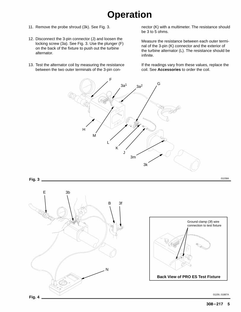
Operation11. Remove the probe shroud (3k). See Fig. 3.
12. Disconnect the 3-pin connector (J) and loosen thelocking screw (3a). See Fig. 3. Use the plunger (F)on the back of the fixture to push out the turbinealternator.
13. Test the alternator coil by measuring the resistancebetween the two outer terminals of the 3-pin con-
nector (K) with a multimeter. The resistance shouldbe 3 to 5 ohms.
Measure the resistance between each outer termi-nal of the 3-pin (K) connector and the exterior ofthe turbine alternator (L). The resistance should beinfinite.
If the readings vary from these values, replace thecoil. See Accessories to order the coil.
Fig. 3
H
F
3a1
3k
3mJ
KL
M
01158A
G3a2
Back V iew of PRO ES T est Fixture
Ground clamp (3f) wireconnection to test fixture
Fig. 4
3f
3b
B
01159, 01887A
E
N

�� � � � ������
OperationTesting the Power Supply Cartridge
NOTE: You do not use the fixture’s 3-pin connector (J)to test the power supply cartridge.
1. Remove the power supply cartridge from the gunas instructed in your spray gun manual and bringthe equipment to a non-hazardous location to dothe testing.
WARNINGTo reduce the risk of fire, explosion, and electricshock, which can result in serious injury and prop-erty damage,
� Never use the PRO ES Test Fixture to test thegun turbine alternator or power supply in a haz-ardous location.
� Never test the power supply without the shroud(3a) installed.
2. Lubricate the power supply’s turbine o-ring. Do notuse a silicone base grease.
3. Install the power supply cartridge (P) into the fix-ture (H), orientated as shown in Fig. 6.
4. PRO 4000 and PRO 5000 Guns Only: Tighten thetop locking screw (3a1) until it feels snug; do notover-tighten.
All Other PRO Gun Models: Tighten the top lock-ing screw (3a1) until its head bottoms out.
5. PRO 4000 and PRO 5000 Guns Only: Insert thealignment sleeve (5) into the shroud (3k).
6. Secure the shroud (3k) to the fixture (H) with thescrew (3m).
7. Lubricate the probe o-ring (2b) with petroleum jellyto ease insertion into the shroud.
8. Insert the probe (2) into the shroud (3k) and touchits tip to the end of the power supply.
9. Connect the probe’s red wire (D) to the KV Meterand its green/yellow ground wire (C) to a true earthground (B). See Fig. 7.
10. Connect the KV Meter’s green/yellow ground wire(4) between the KV Meter and a true earth ground.
11. Connect the fixture’s grounding clamp (3f) to a trueearth ground.
12. Connect an air line (E) to the fixture. Set the airpressure to 25 psi (1.7 bar).
13. Read the power supply cartridge voltage outputwith the KV Meter.
Typical Power Supply V oltage Readings with Test Fixture
PRO 3500 PRO 4000,PRO AA4000,PRO 5000,
PRO AA5000
PRO 4500,PRO AA4500,
PRO 4600
55–65 KVDC 65–75 KVDC 75–85 KVDC
Testing the Power Supply’s ES HI-LO Setting on the PRO 4500, PRO AA4500,and PRO 4600 Spray Guns Only
1. Use the ES HI-LO knob on the back of the fixtureto change the cartridge output to either high volt-age or low voltage setting. See Fig. 5. Install theknob in the hole for the desired voltage setting.
2. If the low voltage setting of your power supply isadjustable, insert a small blade end screw driver(Q) through the fixture, as shown in Fig. 7, and intothe cartridge’s potentiometer to adjust it. Turn thescrew driver clockwise to increase the voltage orcounterclockwise to decrease it. See your guninstruction manual for more information on chang-ing the power supply setting.
Install ES Knob here to test the PRO 4500 and PRO AA4500Guns’ low voltage setting and the PRO 4600 Gun’s highvoltage setting.
Install ES Knob here to test the PRO 4500 and PRO AA4500Guns’ high voltage setting (knob shown in this position).
Install ES Knob here to test the PRO 4600 Gun’s low voltagesetting.
01887AFig. 5
Back V iew of PRO ES T est Fixture
�
�
�
�
�
�

�������� � � � �
Operation
Fig. 6
P
3k
01160A
3mH
2
2b
�
�
5
�
�
PRO 4000 & PRO 5000 Guns: Align the shroud(3k) and screw (3m) here to test the powersupply.
All other PRO Gun Models: Align the shroud (3k)and screw (3m) here to test the power supply.
Lubricate the o-ring (2b) with petroleum jelly.
Use alignment sleeve (5) with PRO 4000 andPRO 5000 Gun power supplies only.
��
3a1
�
�
Back View of PRO ES T est Fixture
Ground clamp (3f) wireconnection to test fixture
Fig. 7
D
C
BQ 4
3f
1
E
01887A, 01161A

�� � � � �������
TroubleshootingProblem Cause Solution
Spray gun test shows low voltage 1. Gun ES HI-LO lever on low;PRO 4500 & PRO AA4500 only
2. Gun ES ON-OFF lever turnedOFF
3. Air pressure to gun too low
4. KV Meter not grounded
5. KV Meter connected wrong
6. Fluid resistivity too low
7. Faulty gun resistance
8. Fluid leaks from needle packingand causes short
9. Dirty gun
10. Faulty power supply
11. Faulty turbine alternator
1. Check lever position.
2. Turn lever ON.
3. Increase air pressure; air pres-sure must be at least 40 psi (2.8bar) at the gun air inlet.
4. Connect the KV Meter groundwire to a true earth ground; seeFig. 1.
5. Correct connection; see Fig. 1.
6. Check fluid resistivity with paintmeter and probe.
7. Check gun resistance; see gunmanual.
8. Clean needle cavity and replacefluid needle assembly.
9. Clean the gun.
10. Test power supply; replace iffaulty.
11. Test alternator; replace orrebuild if faulty.*
Power supply test shows lowvoltage
1. Fixture’s ES Knob is positionedfor low voltage setting
2. Probe is not making contact withpower supply contact
3. KV Meter not grounded
4. KV Meter connected wrong
5. Air pressure to fixture too low
6. Fixture’s air bypass not plugged
7. Faulty alternator
1. Move ES knob to high voltagesetting position; see Fig. 5.
2. Remove the probe, then push itinto the shroud until it pressesfirmly against the power supplycontact.
3. Connect the KV Meter groundwire to a true earth ground; seeFig. 1.
4. Correct connection; see Fig. 1.
5. Increase air pressure; air pres-sure to fixture must be at least25 psi (1.7 bar).
6. Make sure the probe shroud istightly secured to the fixture.
7. Test alternator; replace orrebuild if faulty.*
* See Accessories to order a repair kit.

�������� � � �
TroubleshootingProblem Cause Solution
Turbine alternator test shows nofrequency or voltage
1. No connection to load resistor
2. Alternator coil has open circuit
1. Check connection.
2. Test coil. Resistance should be3 to 5 ohms. Replace coil if nec-essary.*
Turbine alternator test shows fre-quency or voltage is out of range
1. Air pressure to fixture too low
2. Fixture’s air bypass not plugged
3. Alternator bearings worn
4. Coil resistance out of range
5. Alternator armature worn
6. Alternator holes are plugged
1. Increase air pressure; air pres-sure to fixture must be at least25 psi (1.7 bar).
2. Make sure the probe shroud istightly secured to the fixture.
3. Replace or rebuild alternator.*
4. Replace or rebuild alternator.*
5. Replace or rebuild alternator.*
6. Unplug the holes.
Operator get shock 1. Operator not properly grounded
2. Probe not properly grounded
3. Gun not properly grounded
1. Be sure floor is properlygrounded; wear shoes with con-ductive soles or wear personalgrounding straps; be sure oper-ator is not in contact with or car-rying any metallic items whichcould build up electrical charge;if a glove is worn, it must beconductive or modified asshown in your gun manual.
2. Connect the probe’s ground wireto a true earth ground; seeFig. 1.
3. Ground the gun; see your gunmanual.
* See Accessories to order a repair kit.

��� � � � �������
Parts for 236–141Part No. 236–141PRO ES Test Fixture, High Voltage Test Probe, and KV Meter; Includes items 1–6
3e
2a
02119A
3c
3b
3m
3a 3f3k
2
1
4
3a
5
2b
3n
3d3g
3j
3d 3h
RefNo. Part No. Description Qty
1 224–904 KV METER 12 224–911 HIGH VOLTAGE TEST PROBE
Includes item 2a 12a � 187–465 �WARNING LABEL 12b 110–466 �O-RING; Viton� 13 224–888 PRO ES TEST FIXTURE ASSY.
Includes items 3a–3m 13a 187–468 �LOCKING SCREW 23b 223–998 �RESISTOR ASSY. 13c 224–901 �ES HI-LO KNOB 13d 156–823 �FITTING, swivel; 1/4 npt(m) 23e � 187–466 �WARNING LABEL 13f 224–952 �FIXTURE GROUND WIRE ASSY. 1
RefNo. Part No. Description Qty
3g 162–453 �FITTING, 1/4 npsm x 1/4 npt 13h 160–430 �GAUGE, 0–100 psi 13j 100–547 �T-PIPE 13k 224–899 �SHROUD 13m 112–325 SCREW, thumb; 1/4–20 13n 168–518 O-RING; Viton 24 223–267 KV METER GROUND WIRE ASSY.
(green/yellow wire) 15 189–351 ALIGNMENT SLEEVE; for use with
PRO 4000 & PRO 5000 16 112–234 CASE, carrying 1
� Replacement Warning labels are available at no cost.

�������� � � � ��
Parts for 236–003
2a
2
1
4
Part No. 236–003High Voltage Test Probe and KV Meter;Includes items 1, 2, & 4
�����
2b
RefNo. Part No. Description Qty
1 224–904 KV METER 12 224–911 HIGH VOLTAGE TEST PROBE
Includes item 2a 12a � 187–465 �WARNING LABEL 12b 110–466 �O-RING; Viton� 1
RefNo. Part No. Description Qty
4 223–267 KV METER GROUND WIRE ASSY.(green/yellow wire) 1
� Replacement Warning labels are available at no cost.

��� � � � �������
AccessoriesWavetek Multimeter Model DM25XT
The Wavetek Multimeter or an equivalent meter thatcan read voltage and frequency, can be used to testthe turbine alternator. These meters can be purchasedthrough most industrial electronics products distribu-tors.
To order Wavetek Multimeter Model DM25XT, contact:Wavetek CorporationInstruments Division9045 Balboa AvenueSan Diego, CA 92123–1509
Paint Resistance Meter 722–886Used with 722–860 Paint Probe to measure resistance ofpaint. Not for use in Hazardous areas.
Paint Probe 722–860Used with 722–886 Paint Resistance Meter to measure resistance of paint. Not for use in Hazardous areas.
Turbine Alternator Bearing Repair Kit 223–688
The Repair Kit includes items 1–4 (bearings, fan, andspacer tool) shown below. Refer to manual 308–034.
�����
PRO 4000 & PRO 5000 Gun (not included with kit)
1
23
4
Turbine Alternator Coil Repair Kit 223–750
Turbine Alternator Armature 217–590

�������� � � � ��
Technical DataMaximum Air Pressureto PRO ES Test Fixture Inlet 40 psi (2.8 bar). . . . . . . . .
Minimum Air Pressureto PRO ES Test Fixture Inlet 25 psi (1.7 bar). . . . . . . . .
Maximum Testing Voltage 90 kV DC. . . . . . . . . . . . . . . .
KV Probe and Meter Accuracy +5% full scale. . . . . . . .
KV Probe Resistance 7 gigohm +5%. . . . . . . . . . . . . . . .
Multimeter Specifications
To test the PRO gun’s turbine alternator, the multi-meter you use must be able to read voltage andfrequency. See Accessories for multimeter orderinginformation.
Graco PhoneNumbers
TO PLACE AN ORDER , contact your Graco distrib-utor, or call this number to identify the distributorclosest to you: 1–800–328–0211 Toll Free
FOR TECHNICAL ASSISTANCE, service repairinformation or assistance regarding the application ofGraco equipment: 1–800–543–0339 Toll Free
Manual Change Summary
The manual was revised from Rev. A to B to updatethe parts lists, drawings, figure illustrations, and to up-date the testing procedures.

��� � � � ������
Notes

������� � � � ��
Notes

��� � � � ������
The Graco Warranty and DisclaimersWARRANTYGraco warrants all equipment manufactured by it and bearing its name to be free from defects in material and workmanship onthe date of sale by an authorized Graco distributor to the original purchaser for use. As purchaser’s sole remedy for breach of thiswarranty, Graco will, for a period of twelve months from the date of sale, repair or replace any part of the equipment proven defec-tive. This warranty applies only when the equipment is installed, operated and maintained in accordance with Graco’s written rec-ommendations.
This warranty does not cover, and Graco shall not be liable for, any malfunction, damage or wear caused by faulty installation,misapplication, abrasion, corrosion, inadequate or improper maintenance, negligence, accident, tampering, or substitution ofnon–Graco component parts. Nor shall Graco be liable for malfunction, damage or wear caused by the incompatibility with Gracoequipment of structures, accessories, equipment or materials not supplied by Graco, or the improper design, manufacture, instal-lation, operation or maintenance of structures, accessories, equipment or materials not supplied by Graco.
This warranty is conditioned upon the prepaid return of the equipment claimed to be defective to an authorized Graco distributorfor verification of the claim. If the claimed defect is verified, Graco will repair or replace free of charge any defective parts. Theequipment will be returned to the original purchaser transportation prepaid. If inspection of the equipment does not disclose anydefect in material or workmanship, repairs will be made at a reasonable charge, which charges may include the costs of parts,labor and transportation.
DISCLAIMERS AND LIMITATIONSThe terms of this warranty constitute purchaser’s sole and exclusive remedy and are in lieu of any other warranties (express orimplied), including warranty of merchantability or warranty of fitness for a particular purpose , and of any non–contractualliabilities, including product liabilities, based on negligence or strict liability. Every form of liability for direct, special or consequen-tial damages or loss is expressly excluded and denied. In no case shall Graco’s liability exceed the amount of the purchase price.Any action for breach of warranty must be brought within two (2) years of the date of sale.
EQUIPMENT NOT COVERED BY GRACO WARRANTYGraco makes no warranty, and disclaims all implied warranties of merchantability and fitness for a particular purpose , withrespect to accessories, equipment, materials, or components sold but not manufactured by Graco. These items sold, but notmanufactured by Graco (such as electric motor, switches, hose, etc.) are subject to the warranty, if any, of their manufacturer.Graco will provide purchaser with reasonable assistance in making any claim for breach of these warranties.
Sales Offices: Atlanta, Chicago, Dallas, Detroit, Los Angeles, Mt. Arlington (N.J.)Foreign Offices: Canada; England; Korea; Switzerland; France; Germany; Hong Kong; Japan
GRACO INC. P.O. BOX 1441 MINNEAPOLIS, MN 55440–1441PRINTED IN U.S.A. 308–217 5/93 Revised 1/94